EP3441148B1 - Druck- und beschichtungsvorrichtung sowie verfahren - Google Patents
Druck- und beschichtungsvorrichtung sowie verfahren Download PDFInfo
- Publication number
- EP3441148B1 EP3441148B1 EP18179482.7A EP18179482A EP3441148B1 EP 3441148 B1 EP3441148 B1 EP 3441148B1 EP 18179482 A EP18179482 A EP 18179482A EP 3441148 B1 EP3441148 B1 EP 3441148B1
- Authority
- EP
- European Patent Office
- Prior art keywords
- station
- article
- piece
- graphic pattern
- metallization
- Prior art date
- Legal status (The legal status is an assumption and is not a legal conclusion. Google has not performed a legal analysis and makes no representation as to the accuracy of the status listed.)
- Active
Links
Images

Classifications
-
- B—PERFORMING OPERATIONS; TRANSPORTING
- B05—SPRAYING OR ATOMISING IN GENERAL; APPLYING FLUENT MATERIALS TO SURFACES, IN GENERAL
- B05B—SPRAYING APPARATUS; ATOMISING APPARATUS; NOZZLES
- B05B13/00—Machines or plants for applying liquids or other fluent materials to surfaces of objects or other work by spraying, not covered by groups B05B1/00 - B05B11/00
- B05B13/02—Means for supporting work; Arrangement or mounting of spray heads; Adaptation or arrangement of means for feeding work
- B05B13/0221—Means for supporting work; Arrangement or mounting of spray heads; Adaptation or arrangement of means for feeding work characterised by the means for moving or conveying the objects or other work, e.g. conveyor belts
- B05B13/0242—Means for supporting work; Arrangement or mounting of spray heads; Adaptation or arrangement of means for feeding work characterised by the means for moving or conveying the objects or other work, e.g. conveyor belts the objects being individually presented to the spray heads by a rotating element, e.g. turntable
-
- B—PERFORMING OPERATIONS; TRANSPORTING
- B05—SPRAYING OR ATOMISING IN GENERAL; APPLYING FLUENT MATERIALS TO SURFACES, IN GENERAL
- B05B—SPRAYING APPARATUS; ATOMISING APPARATUS; NOZZLES
- B05B16/00—Spray booths
- B05B16/20—Arrangements for spraying in combination with other operations, e.g. drying; Arrangements enabling a combination of spraying operations
-
- B—PERFORMING OPERATIONS; TRANSPORTING
- B41—PRINTING; LINING MACHINES; TYPEWRITERS; STAMPS
- B41J—TYPEWRITERS; SELECTIVE PRINTING MECHANISMS, i.e. MECHANISMS PRINTING OTHERWISE THAN FROM A FORME; CORRECTION OF TYPOGRAPHICAL ERRORS
- B41J3/00—Typewriters or selective printing or marking mechanisms characterised by the purpose for which they are constructed
- B41J3/407—Typewriters or selective printing or marking mechanisms characterised by the purpose for which they are constructed for marking on special material
- B41J3/4073—Printing on three-dimensional objects not being in sheet or web form, e.g. spherical or cubic objects
-
- C—CHEMISTRY; METALLURGY
- C23—COATING METALLIC MATERIAL; COATING MATERIAL WITH METALLIC MATERIAL; CHEMICAL SURFACE TREATMENT; DIFFUSION TREATMENT OF METALLIC MATERIAL; COATING BY VACUUM EVAPORATION, BY SPUTTERING, BY ION IMPLANTATION OR BY CHEMICAL VAPOUR DEPOSITION, IN GENERAL; INHIBITING CORROSION OF METALLIC MATERIAL OR INCRUSTATION IN GENERAL
- C23C—COATING METALLIC MATERIAL; COATING MATERIAL WITH METALLIC MATERIAL; SURFACE TREATMENT OF METALLIC MATERIAL BY DIFFUSION INTO THE SURFACE, BY CHEMICAL CONVERSION OR SUBSTITUTION; COATING BY VACUUM EVAPORATION, BY SPUTTERING, BY ION IMPLANTATION OR BY CHEMICAL VAPOUR DEPOSITION, IN GENERAL
- C23C14/00—Coating by vacuum evaporation, by sputtering or by ion implantation of the coating forming material
- C23C14/02—Pretreatment of the material to be coated
-
- C—CHEMISTRY; METALLURGY
- C23—COATING METALLIC MATERIAL; COATING MATERIAL WITH METALLIC MATERIAL; CHEMICAL SURFACE TREATMENT; DIFFUSION TREATMENT OF METALLIC MATERIAL; COATING BY VACUUM EVAPORATION, BY SPUTTERING, BY ION IMPLANTATION OR BY CHEMICAL VAPOUR DEPOSITION, IN GENERAL; INHIBITING CORROSION OF METALLIC MATERIAL OR INCRUSTATION IN GENERAL
- C23C—COATING METALLIC MATERIAL; COATING MATERIAL WITH METALLIC MATERIAL; SURFACE TREATMENT OF METALLIC MATERIAL BY DIFFUSION INTO THE SURFACE, BY CHEMICAL CONVERSION OR SUBSTITUTION; COATING BY VACUUM EVAPORATION, BY SPUTTERING, BY ION IMPLANTATION OR BY CHEMICAL VAPOUR DEPOSITION, IN GENERAL
- C23C14/00—Coating by vacuum evaporation, by sputtering or by ion implantation of the coating forming material
- C23C14/22—Coating by vacuum evaporation, by sputtering or by ion implantation of the coating forming material characterised by the process of coating
- C23C14/34—Sputtering
- C23C14/3407—Cathode assembly for sputtering apparatus, e.g. Target
- C23C14/3414—Metallurgical or chemical aspects of target preparation, e.g. casting, powder metallurgy
-
- B—PERFORMING OPERATIONS; TRANSPORTING
- B41—PRINTING; LINING MACHINES; TYPEWRITERS; STAMPS
- B41J—TYPEWRITERS; SELECTIVE PRINTING MECHANISMS, i.e. MECHANISMS PRINTING OTHERWISE THAN FROM A FORME; CORRECTION OF TYPOGRAPHICAL ERRORS
- B41J15/00—Devices or arrangements of selective printing mechanisms, e.g. ink-jet printers or thermal printers, specially adapted for supporting or handling copy material in continuous form, e.g. webs
- B41J15/04—Supporting, feeding, or guiding devices; Mountings for web rolls or spindles
- B41J15/048—Conveyor belts or like feeding devices
Definitions
- the present invention relates to an apparatus for articles surface finishing.
- the invention also relates to a finishing process actuatable by means of said apparatus.
- caps, lids, bottles, tubes or other containers having a high degree of surface finishing, exhibiting a metallescent, glossy or satin appearance is very much demanded, for example in the pharmaceutical field, in the cosmetics industry, and so on.
- Such metallescent finishing is generally obtained via sputtering or other PVD technique (Phisical Vapor Deposition) which first provides for application of a primer layer on the surface of the article being processed, that is then subjected to a metallization process.
- PVD Physical Vapor Deposition
- sputter metallization requires that the article be introduced into a high vacuum chamber, inside which a metal target hit by an electromagnetic radiation releases metal particles that deposit in the form of a thin layer (generally of a few nanometers) homogeneously distributed on the exposed surface of the article being processed.
- the article is subjected to a lacquering treatment for the purpose of depositing a transparent, colourless layer or of a predetermined protective colour which, once dried, preserves the underlying metallization layer from mechanical abrasions, atmospheric agents and/or other external agents.
- a surface finishing line of articles operating according to what is described above is, for example, disclosed in US 9,487,857 , in the name of the same Applicant.
- EP 2 121 208 in the name of the same Applicant, provides a process and an apparatus for decorating small objects in which the semi-finished product to be treated is subjected to a physical vapor deposition (PVD) or sputtering treatment, to provide a metallization layer on at least one of its surfaces.
- PVD physical vapor deposition
- a three-dimensional impression is also formed, before or after metallization.
- the metallization layer produced by the PVD treatment has a three-dimensional figure comprising a plurality of projections and/or recesses.
- the three-dimensional impression can be obtained by removing material, e.g by laser marking or other mechanical processing performed by a unit operating downstream of the metallization station, or by mechanical forming at a plastic deformation station placed upstream of the metallization station.
- WO 2005/075170 proposes the application of graphic motifs on previously lacquered articles, in the absence of any superficial metallization process.
- US 9,352,594 in the name of the same applicant, relates to a finishing process of articles by digital printing, in the absence of any metallization treatment.
- the articles are subjected to further handling for the purpose of additional graphic patterns application and final packaging.
- the Applicant also observed that the graphic patterns applied to the articles are directly exposed to rubbing and mechanical stresses, as well as to the action of external atmospheric agents such as humidity and UV radiation that may jeopardize the prolonged maintenance of aesthetic characteristics. It was further observed that in many cases the transparent protective layer applied to protect the metallescent finishing, also for the purpose of meeting particular optical and/or tactile requirements, exhibits physical characteristics which are not compatible with a strong adhesion of the graphic patterns subsequently printed on the article. It follows that the graphic patterns may exhibit a low resistance to mechanical abrasion and wear, thereby compromising maintenance of the product aesthetic characteristics during use.
- a further object of the invention is to promote a permanent and lasting adhesion of the printed graphic patterns, thus offering the possibility of exploiting the protective coating applied at the end of the metallization process in order to obtain, where required, additional protection of the graphic patterns subsequently applied.
- a further object of the present invention is also to provide an apparatus which lends itself to be easily adapted, as the case may be, for application of graphic patterns before and/or after application of the transparent protective layer.
- printed it is meant a graphic pattern produced by printing, i.e. by applying inks, pigments, or paints in liquid or powder form, directly on the surfaces of the article which is being processed or on a film subsequently applied to the article.
- the object of the present invention is an apparatus for articles surface finishing according to claim 1, comprising a transfer line carrying piece-holder members, each configured to retain an article being processed.
- a metallization station operating along the transfer line is configured to deposit a surface metallization layer on each of the articles carried by the piece-holder members.
- a lacquering station operating along the transfer line downstream of the metallization station is configured to deposit a transparent protective layer on the metallization layer of each article carried by the respective piece-holder member.
- a marking station i.e. a printing station, is operatively arranged downstream of the metallization station to provide at least one graphic pattern, preferably applied by printing, on each article carried by the respective piece-holder member.
- the invention relates to a process for articles surface finishing according to claim 10, comprising the action of engaging a plurality of articles being processed on respective piece-holder members, each configured to retain one of said articles.
- the articles held by the piece-holder members are moved along a transfer line.
- a surface metallization layer is deposited on each of the articles held by the piece-holder members.
- a transparent protective layer is deposited on the metallization layer of each article held by the respective piece-holder member.
- a graphic preferably a printed pattern, is also provided on each article held by the respective piece-holder member.
- the invention may further comprise one or more of the following preferred features.
- said printing station is arranged upstream of the lacquering station, whereby the printed graphic pattern is applied beneath the transparent protective layer.
- an additional lacquering station is also provided, which operates downstream of the printing station in order to apply a final covering layer, thereby covering the graphic pattern applied on the transparent protective layer.
- said printing station is arranged downstream of the lacquering station, whereby the printed graphic pattern is applied on the transparent protective layer.
- each piece-holder member is rotatable, together with the respective article, around a predetermined geometric axis.
- orientation devices are also provided for arranging each article according to a predetermined orientation around the respective geometric axis, prior to application of the graphic pattern in the printing station.
- said orientation devices comprise at least one reading unit configured to locate an angular reference index carried by the article in proximity of the printing station, and to emit a positioning signal representative of an angular position presented by the angular reference index around the geometric axis.
- control devices are provided which operate on the piece-holder member in response to said positioning signal, for driving a rotation of the article around said geometric axis and stopping the rotation of the article when the angular reference index reaches a predetermined angular position around the geometric axis.
- a pre-treatment station operating upstream of the metallization station is provided for applying a surface base layer on each of the articles carried by the piece-holder members.
- said transfer line has a forward branch and a return branch placed parallel aside one to the other.
- said at least one marking station is installed in an auxiliary processing module operatively disposed astride both the forward and return branches of the transfer line.
- the auxiliary processing module is operatively arranged in an area interposed between the metallization station and the lacquering station.
- the auxiliary processing module exhibits a first and a second portion symmetrically arranged with respect to the transfer line.
- At least one of said first and second portions houses the marking station.
- the first portion extends from the forward branch of the transfer line, away from the return branch.
- the second portion extends from the return branch, away from the forward branch, specularly with respect to the first portion.
- the application of the graphic pattern is carried out before depositing said transparent protective layer, whereby the printed graphic pattern is applied beneath said protective layer.
- the application of the graphic pattern is carried out after deposition of the transparent protective layer, whereby the printed graphic pattern is applied on said protective layer.
- a final covering layer is also provided, to cover the graphic pattern printed on said transparent protective layer.
- each article is rotatably supported around a predetermined geometric axis.
- each article is arranged according to a predetermined orientation around the respective geometric axis, prior to application of the graphic pattern.
- arranging each article according to a predetermined orientation comprises the action of identifying an angular reference index carried by the article proximate the printing station.
- it is provided to emit a positioning signal representative of an angular position presented by the angular reference index around the geometric axis.
- said positioning signal in response to said positioning signal, it is provided to drive a rotation of the article around said geometric axis and to stop the rotation of the article when the angular reference index reaches a predetermined angular position around the geometric axis.
- a surface base layer is applied to each of the articles carried by the piece-holder members.
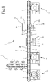
- the apparatus 1 comprises a transfer line 2 along which, for example by means of one or more belt conveyors 3, a plurality of piece-holder members 4 are made to advance.
- the transfer line 2 extends according to a closed line and exhibits a forward branch 2a and a return branch 2b parallel aside one to the other for at least a part of their development, and ending up at a loading-unloading station 5.
- Each piece-holder member 4 is configured to removably engage and retain a respective article 6 being processed.
- each tray 7 is suitable for engaging a predetermined number of piece-holder members 4.
- four piece-holder members 4 are illustrated, albeit each tray can accommodate any number of piece-holder members, for example up to twelve.
- Each piece-holder member 4 can be releasably engaged to the respective tray 7 by means of a support pin 8 which can be axially inserted along a respective cavity 8a, as for example disclosed in US 9,487,857 .
- each piece-holder member 4, and therefore the article 6 retained therefrom is free to rotate about its own predetermined geometric axis Y, coinciding with the geometric axis of the support pin 8.
- the trays 7 positioned on the transfer line 2 at the loading-unloading station 5 advance along a feed direction A and, after passing through a possible conditioning station 9 in which they are cleaned and/or subjected to other preparation treatments, they reach a pre-treatment station 10 which applies a base surface layer (Base Coating) on each of the articles 6 carried by the piece-holder members 4.
- the base layer can be obtained in the form of paint applied by spraying and subsequent drying, optionally with the aid of UV lamps and/or infrared radiation, as disclosed for example in US 9,487,857 .
- each piece-holder member 4 is removed from the tray 7 and transferred onto support pins similar to those of the tray 7 itself, so that each article 6 may be driven in rotation through the respective piece-holder member 4 thus promoting a homogeneous distribution of the surface layer during application.
- a metallization station 11 operates along the transfer line 2, downstream of the pre-treatment station 10.
- the metallization station 11 is configured to deposit a surface metallization layer on each of the articles 6 carried by the piece-holder members 4, preferably via a sputtering process or other PVD technique.
- each tray 7 is picked up by the belt conveyor 3 of the transfer line 2 and introduced, together with the piece-holder members 4 and the articles 6 carried therein, into a sputtering chamber 12 maintained in a high vacuum condition.
- At least one pre-chamber 13 can be interposed which may be alternatively switched between a load-discharge condition, at ambient pressure, in the presence of which the transfer of the tray 7 to or from the transfer line 2 is carried out, and a condition of forced vacuum transfer, in the presence of which the transfer of the tray 7 to or from the sputtering chamber 12 is carried out.
- a lacquering station 14 operates along the transfer line 2 downstream of the metallization station 11.
- the lacquering station 14 is configured to deposit a transparent protective layer (Top Coating) on the metallization layer of each article 6 carried by the respective piece-holder member 4.
- the transparent protective layer can be colourless or, if desired, pigmented according to a desired chromatic tint.
- the protective layer applied in the lacquering station 14 can be obtained in the form of paint applied by spraying and subsequent drying, optionally with the aid of UV lamps and/or infrared radiation.
- each piece-holder member 4 is removed from the tray 7 and transferred on support pins similar to those of the tray 7, so that each article 6 can be driven in rotation through the respective piece-holder member 4, to promote a homogeneous distribution of the protective layer during application.
- auxiliary processing module 15 operatively disposed astride both the forward 2a and return branches 2b of the transfer line 2, in an area interposed between the metallization station 11 and the lacquering station 14.
- the auxiliary processing module 15 has a first and a second portion 15a, 15b symmetrically arranged with respect to the transfer line 2.
- the first portion 15a extends from the forward branch 2a of the transfer line 2, preferably perpendicular thereto, away from the return branch 2b.
- the second portion 15b extends from the return branch 2b, away from the forward branch 2a, specularly with respect to the first portion 15a.
- the apparatus 1 further comprises at least one printing station 16 operatively arranged downstream of the metallization station 11 to apply at least one graphic pattern printed on each article 6.
- the printing station 16 is housed in the auxiliary processing module 15, in at least one of the first and second portions 15a, 15b thereof.
- the printing station 16 is installed in the first portion 15a of the auxiliary processing module 15.
- the printing station 16 operates between the metallization station 11 and the lacquering station 14, upstream of the latter, preferably along the forward branch 2a of the transfer line 2.
- the graphic pattern applied by the printing station 16 is in this case interposed between the metallization layer and the transparent protective layer.
- the graphic pattern is therefore protected from wear phenomena, abrasions and mechanical damages, as well as from the effects of atmospheric agents such as oxidation, humidity or chemical substances with which article 6 can come into contact.
- the second portion 15b of the auxiliary module 15 can in this case be used for the installation of any additional equipment operating along the return branch 2b of the transfer line 2.
- a qualitative control station 23 of the treated articles 6 may be provided.
- the printing station 16 is installed in the second portion 15b of the auxiliary processing module 15.
- the printing station 16 operates downstream of the lacquering station 14, and the graphic pattern is suitable for being applied on the protective layer. Therefore, a transparent pigmented protective layer may be obtained, without the colour of the protective layer influencing the external appearance of the printed graphic pattern.
- An additional lacquering station may be optionally installed downstream of the printing station 16 operating downstream of the lacquering station 14, to apply a transparent, preferably colourless, final covering layer to cover the printed graphic pattern over the protective layer obtained by the lacquering station 14.
- the articles coming from the return branch 2b of the transfer line 2 can be diverted to the pre-treatment station 10 to undergo application of the final covering layer before reaching the loading-unloading station 5.
- the additional lacquering station may, for example, be represented by the pre-treatment station 10.
- a first and a second printing station 16 arranged respectively in the first and second portion 15a, 15b of the auxiliary processing module 15.
- the first and second printing stations 16 respectively give shape to a first and second graphic pattern, respectively arranged inside and outside the transparent protective layer.
- an additional lacquering station installed downstream of the second printing station may be provided for applying a transparent, preferably colourless, final covering layer thus covering the second printed graphic pattern.
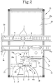
- the printing station 16 can for example comprise at least one loader 17 fed by a manipulator 18.
- the printing station 16 can for example comprise at least one loader 17 fed by a manipulator 18.
- the rotatable structure 19 can be actuated with rotations by 180° about its centre of rotation C, to reciprocally exchange the positions of the trays 7 between a loading area 16a, which can be reached by the manipulator 18, and a working area 16b.
- the manipulator 18 interacts with one of the trays 7 along the transfer line 2, with the piece-holder members 4 being withdrawn in order to remove the articles 6 and release them onto the loader 17 which occupies the loading area 16a.
- the manipulator 18 engages the piece-holder members 4, without coming into contact with the articles 6. It is thus possible to prevent possible damage to the metallization layer and/or the protective layer.
- the loader 17 which received the articles 6 together with the respective piece-holder members 4 is transferred to the working area 16b. Simultaneously, the loader 17 coming from the working area 16b is brought back into the loading area 16a to allow the manipulator 18 to again transfer the processed articles 6 onto the tray 7 waiting on the transfer line 2.
- the articles 6 carried by the loader 17 in the working area 16b are made to advance together with the respective piece-holder members 4 along their mutual alignment direction D, preferably according to a step-by-step movement, in order to be sequentially brought into a printing position P.
- At least one printing unit 20 operates at the printing position P with the former being configured to realize the graphic pattern on the article 6.
- the printing unit 20 can be configured to realize the printed graphic pattern in various ways, for example according to a technique chosen between offset printing, digital printing, decal, pad printing, screen printing or other.
- the printing unit 20 is suitable for operating on a side surface 6a of the article 6 being processed, substantially parallel to the geometric axis Y. It may be provided that during printing the article 6 be rotated through the respective piece-holder member 4 around the geometric axis Y, in order that correct application of the graphic pattern is promoted.
- a printing unit 20 may be provided which is configured to operate on a base surface 6b of article 6, substantially perpendicular to the rotation axis.
- the article 6 being processed is preferably kept stationary during printing.
- the apparatus 1 can further comprise orientation devices 21 configured to arrange each article 6 according to a predetermined orientation around the respective geometric axis Y, prior to application of the graphic pattern in the printing station 16.
- At least one angular reference index 22 is associated with each of the articles 6 being processed, preferably located around its own geometric axis Y.
- This angular reference index 22 may for example be constituted by an insert, a recess or a notch printed or embossed on a side surface 6a of the article 6, or on the piece-holder member 4.
- the angular reference index 22 can possibly be defined by a first graphic pattern, printed for example on the base surface 6b of the article 6, so that a second graphic pattern printed on the side surface 6a is correctly positioned and/or oriented with respect to the first graphic pattern, or vice versa.
- the orientation devices preferably comprise at least one reading unit 21 configured to identify the angular reference index 22 carried by the article 6 in proximity of the printing station 16.
- the reading unit 21 operates in the printing position P, although a different location thereof is not excluded, for example along the transfer line 2
- the reading unit 21 for example of the optical (camera) mechanical (probe) or inductive (proximity magnetic sensor) type, is suitable to emit a positioning signal representative of a position presented by the angular reference index 22 around the geometric axis Y.
- the positioning signal may be emitted when the angular reference index 22 reaches a predetermined angular position around the geometric axis Y of the article 6 being processed, while the latter is made to rotate through the piece-holder member 4 by a motor or other suitable control devices (not shown).
- the control devices stop the rotation of the article 6 when the angular reference index 22 reaches the predetermined angular position around the geometric axis Y.
Landscapes
- Chemical & Material Sciences (AREA)
- Engineering & Computer Science (AREA)
- Chemical Kinetics & Catalysis (AREA)
- Materials Engineering (AREA)
- Mechanical Engineering (AREA)
- Metallurgy (AREA)
- Organic Chemistry (AREA)
- Manufacturing & Machinery (AREA)
- Printing Methods (AREA)
Claims (15)
- Einrichtung für die Oberflächenbearbeitung von Artikeln, umfassend:eine Transferanlage (2), die Stückhalterelemente (4) trägt, von denen ein jedes ausgelegt ist, um einen Artikel (6) zu halten, der bearbeitet wird;eine Metallisierungsstation (11), die entlang der Transferanlage (2) arbeitet und ausgelegt ist, um eine Oberflächenmetallisierungsschicht auf einem jeden der Artikel (6), getragen von den Stückhalterelementen (4), abzulegen;eine Lackierstation (14), die entlang der Transferanlage (2) nach der Metallisierungsstation (11) arbeitet und ausgelegt ist, um eine durchsichtige Schutzschicht auf der Metallisierungsschicht eines jeden Artikels (6), getragen vom jeweiligen Stückhalterelement (4), abzulegen,dadurch gekennzeichnet, dass sie zudem mindestens eine Druckstation (16) umfasst, die betriebswirksam nach der Metallisierungsstation (11) angeordnet ist, um mindestens ein gedrucktes grafisches Muster an einem jeden Artikel (6), getragen vom jeweiligen Stückhalterelement (4), anzubringen.
- Einrichtung nach Anspruch 1, wobei die Druckstation (16) vor der Lackierstation (14) angeordnet ist, wodurch das gedruckte grafische Muster unter der durchsichtigen Schutzschicht angebracht wird.
- Einrichtung nach Anspruch 1, wobei die Druckstation (16) nach der Lackierstation (14) angeordnet ist, wodurch das gedruckte grafische Muster über der durchsichtigen Schutzschicht angebracht wird.
- Einrichtung nach Anspruch 3, zudem umfassend eine zusätzliche Lackierstation, die nach der Druckstation (16) arbeitet, um eine abschließende Abdeckschicht anzubringen, um das grafische Muster, das über der durchsichtigen Schutzschicht angebracht wurde, zu überziehen.
- Einrichtung nach einem oder mehreren der vorhergehenden Ansprüche, wobei ein jedes Stückhalterelement (4) gemeinsam mit dem jeweiligen Artikel (6) rund um eine vorgegebene geometrische Achse (Y) drehbar ist.
- Einrichtung nach einem oder mehreren der vorhergehenden Ansprüche, zudem umfassend Ausrichtungsvorrichtungen (21), die ausgelegt sind, um einen jeden Artikel (6) nach einer vorgegebenen Ausrichtung rund um die jeweilige geometrische Achse (Y) auszurichten, bevor das grafische Muster an der Druckstation (16) angebracht wird.
- Einrichtung nach Anspruch 6, wobei die Ausrichtungsvorrichtungen umfassen:mindestens eine Abtasteinheit (21), die ausgelegt ist, um einen Winkelreferenzindex (22) zu lokalisieren, getragen vom Artikel (6) in der Nähe der Druckstation (16), und um ein Positionierungssignal auszusenden, das repräsentativ für eine Winkelposition ist, die vom Winkelreferenzindex (22) rund um die geometrische Achse (Y) dargestellt ist;Steuervorrichtungen, die auf das Stückhalterelement (4) als Reaktion auf das Positionierungssignal wirken, um eine Drehung des Artikels (6) rund um die geometrische Achse (Y) zu veranlassen und um die Drehung des Artikels (6) zu stoppen, wenn der Winkelreferenzindex (22) eine vorgegebene Winkelposition rund um die geometrische Achse (Y) erreicht.
- Einrichtung nach einem oder mehreren der vorhergehenden Ansprüche, wobei die Transferanlage (2) einen Vorwärtsabzweig (2a) und einen Rückwärtsabzweig (2b) aufweist, die parallel nebeneinander angeordnet sind, wobei mindestens eine Druckstation (16) in einem Hilfsbearbeitungsmodul (15) installiert ist, betriebswirksam gleichauf angeordnet sowohl mit dem Vorwärts- als auch dem Rückwärtsabzweig (2a, 2b) der Transferanlage (2).
- Einrichtung nach Anspruch 8, wobei das Hilfsbearbeitungsmodul (15) einen ersten und einen zweiten Abschnitt (15a, 15b) aufweist, die symmetrisch zur Transferanlage (2) angeordnet sind, wobei die Druckstation (16) entweder im ersten oder im zweiten Abschnitt (15a, 15b) untergebracht ist.
- Verfahren für die Oberflächenbearbeitung von Artikeln, umfassend:das Eingreifen einer Vielzahl an Artikeln (6), die auf jeweiligen Stückhalterelementen (4) bearbeitet werden, ein jeder ausgelegt, um einen der Artikel (6) zu halten;das Bewegen der von den Stückhalterelementen (2) gehaltenen Artikel (6) entlang der Transferanlage (2);in einer Metallisierungsstation (11), die entlang der Transferanlage (2) arbeitet, das Ablegen einer Oberflächenmetallisierungsschicht auf einem jeden der Artikel (6), die von den Stückhalterelementen (4) gehalten werden;in einer Lackierstation (14), die entlang der Transferanlage (2) nach der Metallisierungsstation (11) arbeitet, das Ablegen einer durchsichtigen Schutzschicht auf der Metallisierungsschicht eines jeden vom jeweiligen Stückhalterelement (4) gehaltenen Artikels (6),dadurch gekennzeichnet, dass an jedem vom jeweiligen Stückhalterelement (4) gehaltenen Artikel (6) an einer Druckstation (16), die nach der Metallisierungsstation (11) arbeitet, ein gedrucktes grafisches Muster angebracht wird.
- Verfahren nach Anspruch 10, wobei das Anbringen des grafischen Musters vor dem Ablegen der durchsichtigen Schutzschicht erfolgt, wodurch das gedruckte grafische Muster unter der Schutzschicht angebracht wird.
- Verfahren nach Anspruch 10 oder 11, wobei das Anbringen des grafischen Musters nach dem Ablegen der durchsichtigen Schutzschicht erfolgt, wodurch das gedruckte grafische Muster über der Schutzschicht angebracht wird.
- Verfahren nach Anspruch 12, zudem umfassend das Anbringen einer abschließenden Abdeckschicht, um das über der durchsichtigen Schutzschicht gedruckte grafische Muster zu überziehen.
- Verfahren nach einem oder mehreren der Ansprüche 10 bis 13, wobei ein jeder Artikel (6) drehbar rund um eine vorgegebene geometrische Achse (Y) getragen wird und nach einer vorgegebenen Ausrichtung rund um die jeweilige geometrische Achse (Y) vor dem Anbringen des grafischen Musters angeordnet ist.
- Verfahren nach Anspruch 14, wobei das Anordnen eines jeden Artikels (6) nach einer vorgegebenen Ausrichtung, die Vorgänge umfasst:Lokalisieren eines Winkelreferenzindex (22), getragen vom Artikel (6) in der Nähe der Druckstation (16);Aussenden eines Positionierungssignals, das repräsentativ für eine Winkelposition ist, die vom Winkelreferenzindex (22) rund um die geometrische Achse (Y) dargestellt ist;als Reaktion auf das Positionierungssignal Veranlassen der Drehung des Artikels (6) rund um die geometrische Achse (Y) und Stoppen der Drehung des Artikels (6), wenn der Winkelreferenzindex (22) eine vorgegebene Winkelposition rund um die geometrische Achse (Y) erreicht.
Applications Claiming Priority (1)
| Application Number | Priority Date | Filing Date | Title |
|---|---|---|---|
| IT102017000092402A IT201700092402A1 (it) | 2017-08-09 | 2017-08-09 | Apparato per la finitura superficiale di articoli, e procedimento di finitura attuabile mediante detto apparato |
Publications (2)
| Publication Number | Publication Date |
|---|---|
| EP3441148A1 EP3441148A1 (de) | 2019-02-13 |
| EP3441148B1 true EP3441148B1 (de) | 2020-04-08 |
Family
ID=60991147
Family Applications (1)
| Application Number | Title | Priority Date | Filing Date |
|---|---|---|---|
| EP18179482.7A Active EP3441148B1 (de) | 2017-08-09 | 2018-06-25 | Druck- und beschichtungsvorrichtung sowie verfahren |
Country Status (3)
| Country | Link |
|---|---|
| US (1) | US20190047006A1 (de) |
| EP (1) | EP3441148B1 (de) |
| IT (1) | IT201700092402A1 (de) |
Cited By (1)
| Publication number | Priority date | Publication date | Assignee | Title |
|---|---|---|---|---|
| EP3892386B1 (de) * | 2020-04-09 | 2023-02-08 | TAPEMATIC S.p.A. | Apparat und verfahren für die oberflächenbehandlungen von gegenständen |
Families Citing this family (4)
| Publication number | Priority date | Publication date | Assignee | Title |
|---|---|---|---|---|
| CN109876967B (zh) * | 2019-03-15 | 2022-01-07 | 刘卫进 | 一种金属制品板材表面均匀喷漆装置 |
| CN110216037A (zh) * | 2019-07-05 | 2019-09-10 | 深圳市鸿利昌机械制造有限公司 | 一种自动化喷涂生产装置 |
| CN110614172B (zh) * | 2019-09-30 | 2021-01-12 | 珠海格力智能装备有限公司 | 喷涂装置 |
| CN113499921B (zh) * | 2021-08-04 | 2022-09-06 | 高邮市汽车标准件厂 | 一种具有旋转机构的汽车标准件生产用喷涂装置 |
Family Cites Families (5)
| Publication number | Priority date | Publication date | Assignee | Title |
|---|---|---|---|---|
| JP2007520340A (ja) * | 2004-02-03 | 2007-07-26 | リンデ アクチエンゲゼルシヤフト | 表面塗装装置 |
| TW200715448A (en) * | 2005-07-25 | 2007-04-16 | Canon Anelva Corp | Vacuum processing apparatus, semiconductor device manufacturing method and semiconductor device manufacturing system |
| ITMO20060288A1 (it) * | 2006-09-21 | 2008-03-22 | Dikanta Srl | Metodo, apparato e prodotto |
| US9352594B1 (en) * | 2015-06-30 | 2016-05-31 | Tapematic S.P.A. | Process and apparatus for digital printing on articles |
| ITUB20152328A1 (it) * | 2015-07-20 | 2017-01-20 | Tapematic Spa | Metodo e macchina per la decorazione di oggetti di piccole dimensioni e prodotto ottenibile |
-
2017
- 2017-08-09 IT IT102017000092402A patent/IT201700092402A1/it unknown
-
2018
- 2018-06-25 EP EP18179482.7A patent/EP3441148B1/de active Active
- 2018-07-23 US US16/042,741 patent/US20190047006A1/en not_active Abandoned
Non-Patent Citations (1)
| Title |
|---|
| None * |
Cited By (1)
| Publication number | Priority date | Publication date | Assignee | Title |
|---|---|---|---|---|
| EP3892386B1 (de) * | 2020-04-09 | 2023-02-08 | TAPEMATIC S.p.A. | Apparat und verfahren für die oberflächenbehandlungen von gegenständen |
Also Published As
| Publication number | Publication date |
|---|---|
| US20190047006A1 (en) | 2019-02-14 |
| IT201700092402A1 (it) | 2019-02-09 |
| EP3441148A1 (de) | 2019-02-13 |
Similar Documents
| Publication | Publication Date | Title |
|---|---|---|
| EP3441148B1 (de) | Druck- und beschichtungsvorrichtung sowie verfahren | |
| EP3015176B1 (de) | Zeile zur fertigbearbeitung kleiner dreidimensionaler objekte und entsprechendes verfahren | |
| US11673157B2 (en) | Apparatus and method for the application of surface treatments on articles | |
| CN102892583B (zh) | 利用凸纹对由粗制玻璃或精制玻璃或塑料制成的物品进行装饰的自动化设备和自动化方法 | |
| US9457926B2 (en) | Method and device for treating packaging means by applying decorations | |
| CN101678647A (zh) | 电波透过性转印材料的制造方法 | |
| EP1129232B1 (de) | Vorrichtung zum beschichten von gegenständen mittels pvd | |
| EP2500448A1 (de) | Vorrichtung und Verfahren zum Metallisieren dreidimensionaler, kleinstückiger Gegenstände | |
| WO2017040096A1 (en) | Parallel motion method for depositing a substance on articles | |
| EP3121308A1 (de) | Verfahren und vorrichtung zur behandlung kleiner gegenstände | |
| EP1278706B1 (de) | Herstellungsverfahren von weihnachtsbaumdekorationskörpern und gestelle für die befestigung davon während dieses verfahrens | |
| US10280505B2 (en) | Integrated 3D metallizer | |
| JP2001314788A (ja) | 多色塗装方法及び多色塗装装置 | |
| US8852369B2 (en) | Method and system of manufacturing multilayer coating for decoration of surfaces | |
| EP2248677A1 (de) | Herstellungsverfahren einer mehrschichtigen Beschichtung zur Dekoration von Oberflächen | |
| EP2407315A1 (de) | Verfahren zur Herstellung von Verschlussstopfen für Gefässe | |
| WO2013050816A1 (en) | Method to make a decorative element which can be applied on surfaces and corresponding decorative element | |
| CZ16738U1 (cs) | Zařízení k dekorování předmětů | |
| CZ301436B6 (cs) | Zarízení k dekorování predmetu | |
| WO2012127432A2 (en) | Process and equipment for decorating objects with liquid paints or inks | |
| CA2755636A1 (en) | Method and plant for manufacturing multilayer coating for decoration of surfaces |
Legal Events
| Date | Code | Title | Description |
|---|---|---|---|
| PUAI | Public reference made under article 153(3) epc to a published international application that has entered the european phase |
Free format text: ORIGINAL CODE: 0009012 |
|
| STAA | Information on the status of an ep patent application or granted ep patent |
Free format text: STATUS: THE APPLICATION HAS BEEN PUBLISHED |
|
| STAA | Information on the status of an ep patent application or granted ep patent |
Free format text: STATUS: REQUEST FOR EXAMINATION WAS MADE |
|
| AK | Designated contracting states |
Kind code of ref document: A1 Designated state(s): AL AT BE BG CH CY CZ DE DK EE ES FI FR GB GR HR HU IE IS IT LI LT LU LV MC MK MT NL NO PL PT RO RS SE SI SK SM TR |
|
| AX | Request for extension of the european patent |
Extension state: BA ME |
|
| 17P | Request for examination filed |
Effective date: 20190131 |
|
| RBV | Designated contracting states (corrected) |
Designated state(s): AL AT BE BG CH CY CZ DE DK EE ES FI FR GB GR HR HU IE IS IT LI LT LU LV MC MK MT NL NO PL PT RO RS SE SI SK SM TR |
|
| RIC1 | Information provided on ipc code assigned before grant |
Ipc: B05B 16/20 20180101AFI20191128BHEP |
|
| GRAP | Despatch of communication of intention to grant a patent |
Free format text: ORIGINAL CODE: EPIDOSNIGR1 |
|
| STAA | Information on the status of an ep patent application or granted ep patent |
Free format text: STATUS: GRANT OF PATENT IS INTENDED |
|
| INTG | Intention to grant announced |
Effective date: 20200120 |
|
| GRAS | Grant fee paid |
Free format text: ORIGINAL CODE: EPIDOSNIGR3 |
|
| GRAA | (expected) grant |
Free format text: ORIGINAL CODE: 0009210 |
|
| STAA | Information on the status of an ep patent application or granted ep patent |
Free format text: STATUS: THE PATENT HAS BEEN GRANTED |
|
| AK | Designated contracting states |
Kind code of ref document: B1 Designated state(s): AL AT BE BG CH CY CZ DE DK EE ES FI FR GB GR HR HU IE IS IT LI LT LU LV MC MK MT NL NO PL PT RO RS SE SI SK SM TR |
|
| REG | Reference to a national code |
Ref country code: CH Ref legal event code: EP Ref country code: AT Ref legal event code: REF Ref document number: 1253642 Country of ref document: AT Kind code of ref document: T Effective date: 20200415 |
|
| REG | Reference to a national code |
Ref country code: DE Ref legal event code: R096 Ref document number: 602018003561 Country of ref document: DE |
|
| REG | Reference to a national code |
Ref country code: IE Ref legal event code: FG4D |
|
| REG | Reference to a national code |
Ref country code: NL Ref legal event code: FP |
|
| REG | Reference to a national code |
Ref country code: LT Ref legal event code: MG4D |
|
| PG25 | Lapsed in a contracting state [announced via postgrant information from national office to epo] |
Ref country code: GR Free format text: LAPSE BECAUSE OF FAILURE TO SUBMIT A TRANSLATION OF THE DESCRIPTION OR TO PAY THE FEE WITHIN THE PRESCRIBED TIME-LIMIT Effective date: 20200709 Ref country code: FI Free format text: LAPSE BECAUSE OF FAILURE TO SUBMIT A TRANSLATION OF THE DESCRIPTION OR TO PAY THE FEE WITHIN THE PRESCRIBED TIME-LIMIT Effective date: 20200408 Ref country code: IS Free format text: LAPSE BECAUSE OF FAILURE TO SUBMIT A TRANSLATION OF THE DESCRIPTION OR TO PAY THE FEE WITHIN THE PRESCRIBED TIME-LIMIT Effective date: 20200808 Ref country code: NO Free format text: LAPSE BECAUSE OF FAILURE TO SUBMIT A TRANSLATION OF THE DESCRIPTION OR TO PAY THE FEE WITHIN THE PRESCRIBED TIME-LIMIT Effective date: 20200708 Ref country code: PT Free format text: LAPSE BECAUSE OF FAILURE TO SUBMIT A TRANSLATION OF THE DESCRIPTION OR TO PAY THE FEE WITHIN THE PRESCRIBED TIME-LIMIT Effective date: 20200817 Ref country code: LT Free format text: LAPSE BECAUSE OF FAILURE TO SUBMIT A TRANSLATION OF THE DESCRIPTION OR TO PAY THE FEE WITHIN THE PRESCRIBED TIME-LIMIT Effective date: 20200408 Ref country code: SE Free format text: LAPSE BECAUSE OF FAILURE TO SUBMIT A TRANSLATION OF THE DESCRIPTION OR TO PAY THE FEE WITHIN THE PRESCRIBED TIME-LIMIT Effective date: 20200408 |
|
| REG | Reference to a national code |
Ref country code: AT Ref legal event code: MK05 Ref document number: 1253642 Country of ref document: AT Kind code of ref document: T Effective date: 20200408 |
|
| PG25 | Lapsed in a contracting state [announced via postgrant information from national office to epo] |
Ref country code: HR Free format text: LAPSE BECAUSE OF FAILURE TO SUBMIT A TRANSLATION OF THE DESCRIPTION OR TO PAY THE FEE WITHIN THE PRESCRIBED TIME-LIMIT Effective date: 20200408 Ref country code: LV Free format text: LAPSE BECAUSE OF FAILURE TO SUBMIT A TRANSLATION OF THE DESCRIPTION OR TO PAY THE FEE WITHIN THE PRESCRIBED TIME-LIMIT Effective date: 20200408 Ref country code: RS Free format text: LAPSE BECAUSE OF FAILURE TO SUBMIT A TRANSLATION OF THE DESCRIPTION OR TO PAY THE FEE WITHIN THE PRESCRIBED TIME-LIMIT Effective date: 20200408 Ref country code: BG Free format text: LAPSE BECAUSE OF FAILURE TO SUBMIT A TRANSLATION OF THE DESCRIPTION OR TO PAY THE FEE WITHIN THE PRESCRIBED TIME-LIMIT Effective date: 20200708 |
|
| PG25 | Lapsed in a contracting state [announced via postgrant information from national office to epo] |
Ref country code: AL Free format text: LAPSE BECAUSE OF FAILURE TO SUBMIT A TRANSLATION OF THE DESCRIPTION OR TO PAY THE FEE WITHIN THE PRESCRIBED TIME-LIMIT Effective date: 20200408 |
|
| REG | Reference to a national code |
Ref country code: DE Ref legal event code: R097 Ref document number: 602018003561 Country of ref document: DE |
|
| PG25 | Lapsed in a contracting state [announced via postgrant information from national office to epo] |
Ref country code: MC Free format text: LAPSE BECAUSE OF FAILURE TO SUBMIT A TRANSLATION OF THE DESCRIPTION OR TO PAY THE FEE WITHIN THE PRESCRIBED TIME-LIMIT Effective date: 20200408 Ref country code: ES Free format text: LAPSE BECAUSE OF FAILURE TO SUBMIT A TRANSLATION OF THE DESCRIPTION OR TO PAY THE FEE WITHIN THE PRESCRIBED TIME-LIMIT Effective date: 20200408 Ref country code: CZ Free format text: LAPSE BECAUSE OF FAILURE TO SUBMIT A TRANSLATION OF THE DESCRIPTION OR TO PAY THE FEE WITHIN THE PRESCRIBED TIME-LIMIT Effective date: 20200408 Ref country code: RO Free format text: LAPSE BECAUSE OF FAILURE TO SUBMIT A TRANSLATION OF THE DESCRIPTION OR TO PAY THE FEE WITHIN THE PRESCRIBED TIME-LIMIT Effective date: 20200408 Ref country code: AT Free format text: LAPSE BECAUSE OF FAILURE TO SUBMIT A TRANSLATION OF THE DESCRIPTION OR TO PAY THE FEE WITHIN THE PRESCRIBED TIME-LIMIT Effective date: 20200408 Ref country code: DK Free format text: LAPSE BECAUSE OF FAILURE TO SUBMIT A TRANSLATION OF THE DESCRIPTION OR TO PAY THE FEE WITHIN THE PRESCRIBED TIME-LIMIT Effective date: 20200408 Ref country code: SM Free format text: LAPSE BECAUSE OF FAILURE TO SUBMIT A TRANSLATION OF THE DESCRIPTION OR TO PAY THE FEE WITHIN THE PRESCRIBED TIME-LIMIT Effective date: 20200408 Ref country code: EE Free format text: LAPSE BECAUSE OF FAILURE TO SUBMIT A TRANSLATION OF THE DESCRIPTION OR TO PAY THE FEE WITHIN THE PRESCRIBED TIME-LIMIT Effective date: 20200408 Ref country code: IT Free format text: LAPSE BECAUSE OF FAILURE TO SUBMIT A TRANSLATION OF THE DESCRIPTION OR TO PAY THE FEE WITHIN THE PRESCRIBED TIME-LIMIT Effective date: 20200408 |
|
| PLBE | No opposition filed within time limit |
Free format text: ORIGINAL CODE: 0009261 |
|
| STAA | Information on the status of an ep patent application or granted ep patent |
Free format text: STATUS: NO OPPOSITION FILED WITHIN TIME LIMIT |
|
| PG25 | Lapsed in a contracting state [announced via postgrant information from national office to epo] |
Ref country code: PL Free format text: LAPSE BECAUSE OF FAILURE TO SUBMIT A TRANSLATION OF THE DESCRIPTION OR TO PAY THE FEE WITHIN THE PRESCRIBED TIME-LIMIT Effective date: 20200408 Ref country code: SK Free format text: LAPSE BECAUSE OF FAILURE TO SUBMIT A TRANSLATION OF THE DESCRIPTION OR TO PAY THE FEE WITHIN THE PRESCRIBED TIME-LIMIT Effective date: 20200408 |
|
| 26N | No opposition filed |
Effective date: 20210112 |
|
| PG25 | Lapsed in a contracting state [announced via postgrant information from national office to epo] |
Ref country code: LU Free format text: LAPSE BECAUSE OF NON-PAYMENT OF DUE FEES Effective date: 20200625 |
|
| REG | Reference to a national code |
Ref country code: BE Ref legal event code: MM Effective date: 20200630 |
|
| PG25 | Lapsed in a contracting state [announced via postgrant information from national office to epo] |
Ref country code: IE Free format text: LAPSE BECAUSE OF NON-PAYMENT OF DUE FEES Effective date: 20200625 |
|
| PG25 | Lapsed in a contracting state [announced via postgrant information from national office to epo] |
Ref country code: BE Free format text: LAPSE BECAUSE OF NON-PAYMENT OF DUE FEES Effective date: 20200630 Ref country code: SI Free format text: LAPSE BECAUSE OF FAILURE TO SUBMIT A TRANSLATION OF THE DESCRIPTION OR TO PAY THE FEE WITHIN THE PRESCRIBED TIME-LIMIT Effective date: 20200408 |
|
| REG | Reference to a national code |
Ref country code: CH Ref legal event code: PL |
|
| PG25 | Lapsed in a contracting state [announced via postgrant information from national office to epo] |
Ref country code: LI Free format text: LAPSE BECAUSE OF NON-PAYMENT OF DUE FEES Effective date: 20210630 Ref country code: CH Free format text: LAPSE BECAUSE OF NON-PAYMENT OF DUE FEES Effective date: 20210630 |
|
| PG25 | Lapsed in a contracting state [announced via postgrant information from national office to epo] |
Ref country code: TR Free format text: LAPSE BECAUSE OF FAILURE TO SUBMIT A TRANSLATION OF THE DESCRIPTION OR TO PAY THE FEE WITHIN THE PRESCRIBED TIME-LIMIT Effective date: 20200408 Ref country code: MT Free format text: LAPSE BECAUSE OF FAILURE TO SUBMIT A TRANSLATION OF THE DESCRIPTION OR TO PAY THE FEE WITHIN THE PRESCRIBED TIME-LIMIT Effective date: 20200408 Ref country code: CY Free format text: LAPSE BECAUSE OF FAILURE TO SUBMIT A TRANSLATION OF THE DESCRIPTION OR TO PAY THE FEE WITHIN THE PRESCRIBED TIME-LIMIT Effective date: 20200408 |
|
| PG25 | Lapsed in a contracting state [announced via postgrant information from national office to epo] |
Ref country code: MK Free format text: LAPSE BECAUSE OF FAILURE TO SUBMIT A TRANSLATION OF THE DESCRIPTION OR TO PAY THE FEE WITHIN THE PRESCRIBED TIME-LIMIT Effective date: 20200408 |
|
| P01 | Opt-out of the competence of the unified patent court (upc) registered |
Effective date: 20231004 |
|
| PGFP | Annual fee paid to national office [announced via postgrant information from national office to epo] |
Ref country code: DE Payment date: 20250626 Year of fee payment: 8 |
|
| PGFP | Annual fee paid to national office [announced via postgrant information from national office to epo] |
Ref country code: GB Payment date: 20250617 Year of fee payment: 8 |
|
| PGFP | Annual fee paid to national office [announced via postgrant information from national office to epo] |
Ref country code: NL Payment date: 20250624 Year of fee payment: 8 |
|
| PGFP | Annual fee paid to national office [announced via postgrant information from national office to epo] |
Ref country code: FR Payment date: 20250624 Year of fee payment: 8 |