EP1129232B1 - Vorrichtung zum beschichten von gegenständen mittels pvd - Google Patents
Vorrichtung zum beschichten von gegenständen mittels pvd Download PDFInfo
- Publication number
- EP1129232B1 EP1129232B1 EP99971870A EP99971870A EP1129232B1 EP 1129232 B1 EP1129232 B1 EP 1129232B1 EP 99971870 A EP99971870 A EP 99971870A EP 99971870 A EP99971870 A EP 99971870A EP 1129232 B1 EP1129232 B1 EP 1129232B1
- Authority
- EP
- European Patent Office
- Prior art keywords
- objects
- pvd
- carriers
- preprocessing
- postprocessing
- Prior art date
- Legal status (The legal status is an assumption and is not a legal conclusion. Google has not performed a legal analysis and makes no representation as to the accuracy of the status listed.)
- Expired - Lifetime
Links
- 238000000576 coating method Methods 0.000 title claims abstract description 16
- 239000011248 coating agent Substances 0.000 title claims abstract description 15
- 239000000969 carrier Substances 0.000 claims abstract description 41
- 238000007781 pre-processing Methods 0.000 claims abstract description 24
- 238000012805 post-processing Methods 0.000 claims abstract description 22
- 238000011282 treatment Methods 0.000 claims abstract description 8
- 230000008021 deposition Effects 0.000 claims abstract description 4
- 239000004922 lacquer Substances 0.000 claims description 18
- 238000012545 processing Methods 0.000 claims description 11
- 239000000872 buffer Substances 0.000 claims description 10
- 230000005855 radiation Effects 0.000 claims description 7
- 238000007664 blowing Methods 0.000 claims description 2
- 239000000428 dust Substances 0.000 claims description 2
- 230000001678 irradiating effect Effects 0.000 claims 2
- 238000005240 physical vapour deposition Methods 0.000 description 19
- 229910052751 metal Inorganic materials 0.000 description 10
- 239000002184 metal Substances 0.000 description 10
- 238000000034 method Methods 0.000 description 10
- 238000010276 construction Methods 0.000 description 8
- 238000001465 metallisation Methods 0.000 description 8
- 230000008569 process Effects 0.000 description 8
- 239000004033 plastic Substances 0.000 description 5
- 229920003023 plastic Polymers 0.000 description 5
- 238000005507 spraying Methods 0.000 description 4
- 230000008901 benefit Effects 0.000 description 3
- 238000001755 magnetron sputter deposition Methods 0.000 description 3
- 239000000463 material Substances 0.000 description 3
- 238000000151 deposition Methods 0.000 description 2
- 238000001514 detection method Methods 0.000 description 2
- 238000001704 evaporation Methods 0.000 description 2
- 230000008020 evaporation Effects 0.000 description 2
- 230000001681 protective effect Effects 0.000 description 2
- RYGMFSIKBFXOCR-UHFFFAOYSA-N Copper Chemical compound [Cu] RYGMFSIKBFXOCR-UHFFFAOYSA-N 0.000 description 1
- 230000009471 action Effects 0.000 description 1
- 239000004411 aluminium Substances 0.000 description 1
- 229910052782 aluminium Inorganic materials 0.000 description 1
- XAGFODPZIPBFFR-UHFFFAOYSA-N aluminium Chemical compound [Al] XAGFODPZIPBFFR-UHFFFAOYSA-N 0.000 description 1
- 230000008859 change Effects 0.000 description 1
- 238000004040 coloring Methods 0.000 description 1
- 229910052802 copper Inorganic materials 0.000 description 1
- 239000010949 copper Substances 0.000 description 1
- 239000002537 cosmetic Substances 0.000 description 1
- 238000001035 drying Methods 0.000 description 1
- 239000011521 glass Substances 0.000 description 1
- PCHJSUWPFVWCPO-UHFFFAOYSA-N gold Chemical compound [Au] PCHJSUWPFVWCPO-UHFFFAOYSA-N 0.000 description 1
- 229910052737 gold Inorganic materials 0.000 description 1
- 239000010931 gold Substances 0.000 description 1
- 230000007246 mechanism Effects 0.000 description 1
- 239000003973 paint Substances 0.000 description 1
- 238000005192 partition Methods 0.000 description 1
- 238000001556 precipitation Methods 0.000 description 1
- 238000004544 sputter deposition Methods 0.000 description 1
- 238000007738 vacuum evaporation Methods 0.000 description 1
- 239000002699 waste material Substances 0.000 description 1
Images


Classifications
-
- C—CHEMISTRY; METALLURGY
- C23—COATING METALLIC MATERIAL; COATING MATERIAL WITH METALLIC MATERIAL; CHEMICAL SURFACE TREATMENT; DIFFUSION TREATMENT OF METALLIC MATERIAL; COATING BY VACUUM EVAPORATION, BY SPUTTERING, BY ION IMPLANTATION OR BY CHEMICAL VAPOUR DEPOSITION, IN GENERAL; INHIBITING CORROSION OF METALLIC MATERIAL OR INCRUSTATION IN GENERAL
- C23C—COATING METALLIC MATERIAL; COATING MATERIAL WITH METALLIC MATERIAL; SURFACE TREATMENT OF METALLIC MATERIAL BY DIFFUSION INTO THE SURFACE, BY CHEMICAL CONVERSION OR SUBSTITUTION; COATING BY VACUUM EVAPORATION, BY SPUTTERING, BY ION IMPLANTATION OR BY CHEMICAL VAPOUR DEPOSITION, IN GENERAL
- C23C14/00—Coating by vacuum evaporation, by sputtering or by ion implantation of the coating forming material
- C23C14/22—Coating by vacuum evaporation, by sputtering or by ion implantation of the coating forming material characterised by the process of coating
- C23C14/56—Apparatus specially adapted for continuous coating; Arrangements for maintaining the vacuum, e.g. vacuum locks
-
- B—PERFORMING OPERATIONS; TRANSPORTING
- B05—SPRAYING OR ATOMISING IN GENERAL; APPLYING FLUENT MATERIALS TO SURFACES, IN GENERAL
- B05D—PROCESSES FOR APPLYING FLUENT MATERIALS TO SURFACES, IN GENERAL
- B05D5/00—Processes for applying liquids or other fluent materials to surfaces to obtain special surface effects, finishes or structures
- B05D5/06—Processes for applying liquids or other fluent materials to surfaces to obtain special surface effects, finishes or structures to obtain multicolour or other optical effects
- B05D5/067—Metallic effect
-
- C—CHEMISTRY; METALLURGY
- C23—COATING METALLIC MATERIAL; COATING MATERIAL WITH METALLIC MATERIAL; CHEMICAL SURFACE TREATMENT; DIFFUSION TREATMENT OF METALLIC MATERIAL; COATING BY VACUUM EVAPORATION, BY SPUTTERING, BY ION IMPLANTATION OR BY CHEMICAL VAPOUR DEPOSITION, IN GENERAL; INHIBITING CORROSION OF METALLIC MATERIAL OR INCRUSTATION IN GENERAL
- C23C—COATING METALLIC MATERIAL; COATING MATERIAL WITH METALLIC MATERIAL; SURFACE TREATMENT OF METALLIC MATERIAL BY DIFFUSION INTO THE SURFACE, BY CHEMICAL CONVERSION OR SUBSTITUTION; COATING BY VACUUM EVAPORATION, BY SPUTTERING, BY ION IMPLANTATION OR BY CHEMICAL VAPOUR DEPOSITION, IN GENERAL
- C23C14/00—Coating by vacuum evaporation, by sputtering or by ion implantation of the coating forming material
- C23C14/22—Coating by vacuum evaporation, by sputtering or by ion implantation of the coating forming material characterised by the process of coating
- C23C14/50—Substrate holders
- C23C14/505—Substrate holders for rotation of the substrates
-
- C—CHEMISTRY; METALLURGY
- C23—COATING METALLIC MATERIAL; COATING MATERIAL WITH METALLIC MATERIAL; CHEMICAL SURFACE TREATMENT; DIFFUSION TREATMENT OF METALLIC MATERIAL; COATING BY VACUUM EVAPORATION, BY SPUTTERING, BY ION IMPLANTATION OR BY CHEMICAL VAPOUR DEPOSITION, IN GENERAL; INHIBITING CORROSION OF METALLIC MATERIAL OR INCRUSTATION IN GENERAL
- C23C—COATING METALLIC MATERIAL; COATING MATERIAL WITH METALLIC MATERIAL; SURFACE TREATMENT OF METALLIC MATERIAL BY DIFFUSION INTO THE SURFACE, BY CHEMICAL CONVERSION OR SUBSTITUTION; COATING BY VACUUM EVAPORATION, BY SPUTTERING, BY ION IMPLANTATION OR BY CHEMICAL VAPOUR DEPOSITION, IN GENERAL
- C23C14/00—Coating by vacuum evaporation, by sputtering or by ion implantation of the coating forming material
- C23C14/22—Coating by vacuum evaporation, by sputtering or by ion implantation of the coating forming material characterised by the process of coating
- C23C14/56—Apparatus specially adapted for continuous coating; Arrangements for maintaining the vacuum, e.g. vacuum locks
- C23C14/568—Transferring the substrates through a series of coating stations
Definitions
- the present invention relates to an apparatus for coating objects by means of PVD (Physical Vapour Deposition), comprising:
- Such apparatus are generally known. They are for instance used to apply a thin layer of metal on plastics to give the object the appearance of metal. Examples hereof are for instance caps for cosmetics bottles, prizes such as presented at sporting events, car components and the like.
- the objects for processing are placed on racks and provided with a lacquer coating.
- This lacquer coating enhances adhesion between the plastic from which the object is made and the metal coating to be applied thereto.
- the lacquer coating moreover provides a smooth surface, so that the reflection of the metal to be coated thereon is improved.
- the pretreatment can also comprise a treatment prior to lacquering, such as a flame treatment.
- a treatment prior to lacquering such as a flame treatment.
- the surface properties of the plastic object are hereby changed so that the lacquer adheres better to the plastic.
- the objects for processing are subsequently placed in a vacuum vessel.
- PVD Physical Vapour Deposition
- the objects are thereafter subjected to a posttreatment, which is generally formed by a new lacquer treatment. It is pointed out here that the applied metal layer is extremely thin and is easily damaged. In order to protect this layer a protective lacquer coating is therefore applied. This lacquer coating further provides the option of changing the colour. In general use is made of aluminium as PVD material, wherein it is possible by colouring the lacquer to change the colour to for instance gold or copper colour.
- a problem with this method generally used heretofore is that many operations must inevitably be performed manually, requiring much human labour. This is caused by the discontinuous character of the PVD process and by the relatively long drying time of the lacquers once they have been applied to the plastic objects. The work is moreover usually difficult.
- WO-A-97/28290 discloses an apparatus for applying at least one coating to objects by means of vapour deposition (PVD) under vacuum, comprising:
- This prior art apparatus is adapted to procedure cathode ray tubes, involving the sputtering of metal coatings on glass.
- the aim of the invention is to provide an apparatus which is adapted to apply a metal coat on materials, which can only be coated if they have been covered by a coat of lacquer .
- the apparatus comprises:
- the semi-continuous character of the PVD device enables successive treatment of the carriers with a series of objects. Because the transport device is adapted for this purpose, and moreover extends through the preprocessing device and postprocessing device, it becomes possible to treat the objects for vapour deposition without loading and unloading operations. This combination of measures thus enables the use of a certain degree of automation; only at the start do the objects have to be placed on the carriers, and after completion of the postprocessing they can be removed therefrom. Handling of the objects between the treatments, albeit placed on racks, is dispensed with.
- the carriers are elongate and the transport device is adapted to move the carriers substantially in the longitudinal direction.
- the transport device has a closed configuration and extends in two directions through the PVD device.
- buffers between the preprocessing device and the PVD device, and between the PVD device and the postprocessing device have the function of compensating for the semi-continuity of the process performed in the PVD devices.
- the buffers are adapted to move the carriers in transverse direction, the buffers take up less space.
- the preprocessing device comprises a blower device for blowing dust from the objects for treating.
- This blower device is preferably adapted to blow ionized air.
- the carriers are provided with interchangeable object holders.
- This measure provides the advantage that the carriers can be used for different types of object; only the object holders have to be exchanged. This is particularly important in respect of the cost of the carriers; these carriers after all comprise expensive components manufactured with great precision.
- the toothed wheels are preferably arranged under the top side of the carrier. This provides the option of arranging protective means, so that lacquer dripping from the objects cannot reach the toothed wheels.
- the toothed wheels are let into openings arranged in the carrier and the toothed wheels protrude outside the side walls of the carrier.
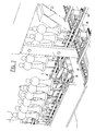
- FIG. 1 shows a metallizing apparatus designated in its entirety as 1. Broadly speaking, this metallizing apparatus is formed by a magnetron sputtering device 2, a preprocessing device 3 and a postprocessing device 4. Extending through each of these devices is a transport device 5. A shunting area 6 is arranged between preprocessing device 3 and PVD device 2 and between PVD device 2 and postprocessing device 4.
- This shunting area serves to compensate for timing differences between the continuously operating preprocessing device 3 and postprocessing device 4 and the semi-continuously operating PVD device 2.
- Transport device 5 is closed and extends in both directions through PVD device 2. Between postprocessing device 4 and preprocessing device 3 the transport device 5 extends through a loading and unloading zone 7.
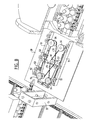
- FIG. 2 This loading and unloading zone is further shown in figure 2.
- transport device 5 has a U-shape at this location.
- rotation devices 20 each comprising a rotating disc 21.
- rotating discs 21 By means of rotating discs 21 it is possible to rotate carrier 15 through an angle of 90°.
- the drive device which is integrated into transport device 5.
- a pushing element 22 drivable by a linear drive element 23 arranged above the rotating disc.
- the objects 24 for processing are placed on carriers 15 on that part of the transport device 5 placed between the two rotation devices 20. This part forms the loading zone 7A.
- the finished products 24 can be taken off the part of transport device 5 preceding rotation device 20. This is the unloading zone 7B.
- Figure 2 further shows how a check gate 25 is placed after the second rotation device 20 for checking the presence of and the location in a plane perpendicular to the direction of movement of the objects for treating.
- the presence detection is important for controlling for instance the lacquer device, so as to prevent an excessive quantity of lacquer being wasted by spraying while no object is passing.
- the location detection serves to prevent objects placed askew on the holders from disrupting the movement of the carriers, whereby objects could become jammed or fall off. This would result in stopping of the process, removal of the objects in question and restarting of the process.
- the first gate 25 placed after the loading station therefore serves mainly to determine whether the objects are placed correctly.
- Such a gate is also placed before the vacuum device.
- the position of the objects is after all critical, and space is limited, this being particularly important in the case of large objects.
- the location of the objects on the carrier may have been changed due to the action of the spraying device.
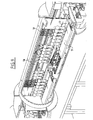
- Figure 3 further shows the construction of transport device 5 at the location of unloading zone 7B.
- Shown in figure 3 is that part. of the transport device which functions as unloading station.
- the transport device comprises two tubular profiles 26 which are provided at regular distances on their underside with bearing units 27, in which are mounted shafts 28.
- a support wheel 29 is arranged on each of the shafts 28.
- two U-shaped profiles 30 which are each fixed against tubular profiles 27.
- a drive chain 31 which is provided with catch elements 32 for moving the carriers 15 along. The chain is guided back again via the underside of the transport device.
- This transport device extends through the entire apparatus according to the invention.
- Carriers 15 are each formed by a carrier body 36, in which are mounted vertically extending shafts 16.
- Carrier body 36 is provided with recesses 18 through which shafts 16 extend and wherein toothed wheels 17 are arranged on the shafts at the location of recesses 18. These toothed wheels 17 serve to drive the shafts in rotation when for instance a gear rack or movable chain is arranged along the sides of profile 26.
- Each of the shafts are provided on their top with a recess 33 on which extension shafts 34 can be placed.
- Product holders adapted to the product for processing which will be described with reference to figure 10, can then be placed on top of extension shafts 34. It is pointed out here that it is possible to use extension shafts 34 of different heights, so that it is possible to adjust the height of the objects for processing on the carriers.
- a part of the profile 30 can otherwise be folded down at the location of unloading station 7B, so that carriers 15 can be taken away.
- a buffer device 6 which provides the synchronization of the essentially continuously operating preprocessing and postprocessing device and the semi-continuously operating vacuum metallization device.
- Buffer device 6 is formed essentially by a frame 35 on which are placed two shafts 37, one of which is drivable by means of a motor 38.
- a chain wheel 39 is placed on each of the shafts 37, wherein a chain 40 is trained around each pair of chain wheels 39.
- Supports 41 are arranged between the two chains 40 for transporting carriers 15.
- Shaft 36 is herein set into intermittent rotation such that supports 41 move intermittently.
- the carriers from UV radiation device 10 are loaded onto the support 41 placed in line with transport device 5, while the carrier then placed in front of the transport device of the vacuum metallization device is simultaneously pushed onto the transport device of the metallization device by means of a pushing device 42.
- a carrier coming from the metallization device is simultaneously pushed onto the relevant support 41 and a carrier placed in front of the transport device of the UV lacquer spraying device 12 is pushed onto the relevant transport device.
- the device in question then moves one full stroke, whereafter this process is repeated.
- Figure 5 shows how a pushing device 42 is arranged for pushing a carrier 15 onto the relevant support 41.
- This pushing device 42 is herein driven by a linear drive member 43.
- This device further shows how the shafts 16 of carrier 15 can be driven in rotation by means of toothed wheels 17, this independently of the linear movement of carrier 15.
- a chain 46 a part of which is arranged parallel to the direction of movement of carrier 15 and which can be driven independently of the transport movement. It will be apparent that it is possible to make use instead of for instance gear racks. These are then arranged fixedly so that the rotation movement is in fact coupled to the transport movement.
- Figure 7 shows in more detail the mechanism with which the movements of supports 41 to the transport device 5 within the vacuum metallization device are executed, and vice versa.
- Figure 8 shows in more detail a part of the drive device for transport of carriers 15 inside the vacuum metallization device.
- the relevant elements are herein mounted on a plate 50, on which are arranged two beams 51 on which guide wheels with guide shafts 52 are mounted. In the middle of each of these beams 51 a guide wheel 52 is further arranged on the other side of the path of the carrier. Finally, support wheels 53 are arranged.
- Drive wheels 55 are also arranged for driving the carrier 15.
- Drive wheels 54 are herein driven by means of belts 55. Both belts 55 are trained round a wheel 56 which is driven by a motor mounted beneath the plate. This drawing also shows that a check gate device is again placed in order to determine whether all objects are present on the carrier.
- FIG 9 shows the construction of the vacuum metallization chamber 4, which otherwise forms the subject-matter of the European patent application 98.203444.9. Here also the same drive device is used. This is further of importance in that plates 57 are arranged to protect the transport device against precipitation of metal. Such plates are otherwise also arranged in the paint spraying devices.
- This figure further shows how the actual targets 58 of the magnetron sputtering device are arranged at two different levels. In combination with the different heights of the extension shafts it is thus possible to determine the height and direction of the metallization process.
- the objects for processing pass twice through the magnetron sputtering device, wherein only one of the two passages is effective.
- the active half of the device is separated from the non-active half of the device by a partition wall 59 of a material on which the sputtered vapour will deposit but which can be removed easily.
- figure 10 shows the construction of product carriers 15.
- the product carriers are placed on top of the extension shafts to carry the products for processing.
- the product carriers are formed by a piece of threaded end which can be placed on the extension shaft, wherein discs provided with internal thread can be placed on the threaded ends, the form and position of which discs can be adapted to the relevant products.
Landscapes
- Chemical & Material Sciences (AREA)
- Chemical Kinetics & Catalysis (AREA)
- Engineering & Computer Science (AREA)
- Materials Engineering (AREA)
- Mechanical Engineering (AREA)
- Metallurgy (AREA)
- Organic Chemistry (AREA)
- Physical Vapour Deposition (AREA)
- Application Of Or Painting With Fluid Materials (AREA)
- Coating Apparatus (AREA)
- Paints Or Removers (AREA)
- Non-Silver Salt Photosensitive Materials And Non-Silver Salt Photography (AREA)
Claims (18)
- Vorrichtung zur Aufbringung wenigstens eines Überzuges auf Gegenstände mittels einer Dampfablagerung (PVD) unter Unterdruck, aufweisend:dadurch gekennzeichnet, dass die Vorverarbeitungsvorrichtung eine Anwendungsvorrichtung zum Aufbringen eines Lackes auf die zu behandelnden Gegenstände aufweist, der mittels Strahlung, beispielsweise UV- oder IR-Strahlung, aushärtet, und eine Vorrichtung zum Bestrahlen der lackierten Gegenstände mit der relevanten Strahlung.eine PVD-Vorrichtung zum Überziehen des Gegenstandes unter Unterdruck;wenigstens eine Schleuse, die die PVD-Vorrichtung von der Umgebung trennt;eine Transportvorrichtung, die sich durch die PVD-Vorrichtung und in die Schleuse hinein erstreckt;wobei die Transportvorrichtung dazu angepasst ist, Gegenstände, die auf Trägern angeordnet sind, zu transportieren,die PVD-Richtung für eine halbkontinuierliche Behandlung der Gegenstände, die auf den Trägern angeordnet sind, angepasst ist,eine Vorverarbeitungsvorrichtung zur Durchführung einer Vorverarbeitung an dem Gegenstand;eine Nachverarbeitungsvorrichtung zum Nachverarbeiten der Gegenstände, undwobei sich die Transportvorrichtung durch die wenigstens eine Schleuse, die Vorverarbeitungsvorrichtung und die Nachverarbeitungsvorrichtung erstreckt,
- Vorrichtung gemäß Anspruch 1, dadurch gekennzeichnet, dass die Nachverarbeitungsvorrichtung eine Gebläsevorrichtung zum Ausblasen von Staub von den zu behandelnden Gegenständen aufweist.
- Vorrichtung gemäß Anspruch 1 oder 2, dadurch gekennzeichnet, dass die Vorverarbeitungsvorrichtung eine Oberflächenverarbeitungsvorrichtung aufweist, die vor der Anwendungsvorrichtung zur Bearbeitung der Oberfläche der zu behandelnden Gegenstände verbunden ist.
- Vorrichtung gemäß einem der vorhergehenden Ansprüche, dadurch gekennzeichnet, dass die Nachverarbeitungsvorrichtung eine Anwendungsvorrichtung zum Aufbringen eines Lackes,auf die zu behandelnden Gegenstände aufweist, der mit Strahlung, beispielsweise W-Strahlung aushärtet, und eine Vorrichtung zur Bestrahlung der lackierten Gegenstände mit der relevanten Bestrahlung.
- Vorrichtung gemäß einem der vorhergehenden Ansprüche, dadurch gekennzeichnet, dass eine Beladungs-/Entladungs-Station zwischen der Nachverarbeitungsvorrichtung und der vorverarbeitungsvorrichtung zum Entladen der bearbeiteten Gegenstände und zum Beladen von zu bearbeitenden Gegenständen angeordnet ist.
- Vorrichtung gemäß einem der vorhergehenden Ansprüche, dadurch gekennzeichnet, dass die Träger länglich sind, dass sich Gegenstandshalter auf den Trägern befinden, dass die Gegenstandshalter drehbar sind und die Transportvorrichtung dazu angepasst ist, die Träger im wesentlichen in der Längsrichtung zu bewegen und die Gegenstandshalter in der PVD-Vorrichtung zu drehen.
- Vorrichtung gemäß Anspruch 6, dadurch gekennzeichnet, dass die PVD-Vorrichtung mittels einer einzigen Schleuse mit der Umgebung verbunden ist, sich die Transportvorrichtung durch die Schleuse erstreckt und die Schleuse dazu angepasst ist, einen Träger gleichzeitig in und aus der PVD-Vorrichtung zu transportieren.
- Vorrichtung gemäß Anspruch 7, dadurch gekennzeichnet, dass die Transportvorrichtung eine geschlossene Konfiguration besitzt und sich in zwei Richtungen durch die PVD-Vorrichtung erstreckt.
- Vorrichtung gemäß Anspruch 8, dadurch gekennzeichnet, dass ein Puffer für die Träger zwischen der Vorverarbeitungsvorrichtung und der PVD-Vorrichtung angeordnet ist.
- Vorrichtung gemäß Anspruch 9, dadurch gekennzeichnet, dass ein Puffer für die Träger zwischen der PVD-Vorrichtung und der Nachverarbeitüngsvorrichtung angeordnet ist.
- Vorrichtung gemäß Anspruch 9 oder 10, dadurch gekennzeichnet, dass die Puffer dazu angepasst sind, die Träger in einer transversalen Richtung zu bewegen.
- Vorrichtung gemäß einem der Ansprüche 6 bis 11, dadurch gekennzeichnet, dass die Gegenstandshalter austauschbare Gegenstandshalter sind.
- Vorrichtung gemäß Anspruch 12, dadurch gekennzeichnet, dass die Gegenstandshalter auf sich vertikal erstreckenden Wellen angeordnet sind, die drehbar in den Trägern montiert sind.
- Vorrichtung gemäß Anspruch 13, dadurch gekennzeichnet, dass gezahnte Räder auf den Wellen zum drehenden Antreiben der Wellen angeordnet sind.
- Vorrichtung gemäß Anspruch 14, dadurch gekennzeichnet, dass gezahnte Räder unter der Oberseite des Trägers angeordnet sind.
- Vorrichtung gemäß Anspruch 15, dadurch gekennzeichnet, dass die gezahnten Räder in Öffnungen eingelassen werden, die in dem Träger angeordnet sind, und dass die gezahnten Räder aus den Seitenwänden des Trägers hervorstehen.
- Vorrichtung gemäß einem der Ansprüche 6 bis 16, dadurch gekennzeichnet, dass die Vorrichtung mit Nocken versehen ist, um mit den gezahnten Rädern während des Durchlaufs der Träger in Eingriff zu gelangen und die gezahnten Räder zu drehen.
- Vorrichtung gemäß Anspruch 17, dadurch gekennzeichnet, dass die Nocken einen Teil einer antreibbaren Kette bilden, um die Wellen dazu zu bringen, unabhängig von der linearen Bewegung des Trägers zu rotieren.
Applications Claiming Priority (3)
| Application Number | Priority Date | Filing Date | Title |
|---|---|---|---|
| NL1010531A NL1010531C2 (nl) | 1998-11-11 | 1998-11-11 | Inrichting en werkwijze voor het door middel van opdampen (PVD) op voorwerpen aanbrengen van een laag. |
| NL1010531 | 1998-11-11 | ||
| PCT/NL1999/000689 WO2000028105A1 (en) | 1998-11-11 | 1999-11-11 | Apparatus and method for coating objects through pvd |
Publications (2)
| Publication Number | Publication Date |
|---|---|
| EP1129232A1 EP1129232A1 (de) | 2001-09-05 |
| EP1129232B1 true EP1129232B1 (de) | 2003-10-01 |
Family
ID=19768120
Family Applications (1)
| Application Number | Title | Priority Date | Filing Date |
|---|---|---|---|
| EP99971870A Expired - Lifetime EP1129232B1 (de) | 1998-11-11 | 1999-11-11 | Vorrichtung zum beschichten von gegenständen mittels pvd |
Country Status (10)
| Country | Link |
|---|---|
| EP (1) | EP1129232B1 (de) |
| AT (1) | ATE251234T1 (de) |
| AU (1) | AU1190600A (de) |
| CA (1) | CA2350492C (de) |
| DE (1) | DE69911804T2 (de) |
| DK (1) | DK1129232T3 (de) |
| ES (1) | ES2204195T3 (de) |
| NL (1) | NL1010531C2 (de) |
| PT (1) | PT1129232E (de) |
| WO (1) | WO2000028105A1 (de) |
Cited By (5)
| Publication number | Priority date | Publication date | Assignee | Title |
|---|---|---|---|---|
| CN100476019C (zh) * | 2005-09-30 | 2009-04-08 | 中华映管股份有限公司 | 物理气相沉积的升降机构 |
| ITMI20090933A1 (it) * | 2009-05-27 | 2010-11-28 | Protec Surface Technologies S R L | Apparato per la deposizione di film di rivestimento |
| US9297064B2 (en) | 2009-01-16 | 2016-03-29 | Marca Machinery, Llc | In-line metallizer assemblies and part-coating conveyor systems incorporating the same |
| US9809878B2 (en) | 2009-01-16 | 2017-11-07 | Marca Machinery, Llc | In-line metallizer assemblies and part-coating conveyor systems incorporating the same |
| EP4721873A1 (de) * | 2024-10-07 | 2026-04-08 | TAPEMATIC S.p.A. | Vorrichtung und verfahren zur aufbringung von oberflächenbehandlungen auf gegenständen |
Families Citing this family (10)
| Publication number | Priority date | Publication date | Assignee | Title |
|---|---|---|---|---|
| WO2003064723A1 (en) * | 2002-01-31 | 2003-08-07 | Jamar Venture Corporation | Production line and method for continuous diffusion surface alloying and diffusion carbide surface alloying |
| CN100408721C (zh) * | 2002-08-19 | 2008-08-06 | 乐金电子(天津)电器有限公司 | 热交换器表面处理装置 |
| EP1651359A2 (de) * | 2003-07-24 | 2006-05-03 | EISENMANN Maschinenbau GmbH & Co. KG | Vorrichtung zur aushärtung einer aus einem material, das unter elektromagnetischer strahlung aushärtet, insbesondere aus einem uv-lack oder thermisch aushärtendem lack bestehenden beschichtung eines gegenstandes |
| EP2100714B1 (de) | 2008-03-10 | 2013-04-03 | Albéa Services | Verkettete Formung und Metallisierung |
| CN101608301B (zh) * | 2009-06-24 | 2011-12-07 | 江苏常松机械集团有限公司 | 连续真空等离子蒸发金属复合材料生产线 |
| ITMI20110432A1 (it) * | 2011-03-18 | 2012-09-19 | Tapematic Spa | Macchina e metodo per la metallizzazione di oggetti tridimensionali di piccole dimensioni |
| ITMI20121358A1 (it) * | 2012-08-01 | 2014-02-02 | Tapematic Spa | Macchina per la verniciatura e linea per la finitura di oggetti tridimensionali di piccole dimensioni e relativi metodi |
| MX386755B (es) * | 2012-10-19 | 2025-03-19 | Marca Machinery Llc | Ensambles metalizadores en línea y sistemas transportadores para el revestimiento de partes que incorporan los mismos. |
| FR3042698A1 (fr) | 2015-10-22 | 2017-04-28 | Les Laboratoires Osteal Medical | Dispositifs de support pour supporter des implants ou des protheses |
| DE112021006849T5 (de) * | 2021-01-19 | 2023-11-16 | Shibaura Machine Co., Ltd. | Oberflächenbehandlungseinrichtung und Verfahren zur Oberflächenbehandlung |
Family Cites Families (8)
| Publication number | Priority date | Publication date | Assignee | Title |
|---|---|---|---|---|
| DE2109061A1 (en) * | 1970-02-27 | 1971-09-09 | Varian Associates | Vacuum coating of multiface substrate |
| JPS53130779A (en) * | 1977-04-20 | 1978-11-15 | Mitsubishi Rayon Co Ltd | Molded metallized plastic article and its manufacture |
| JPS60184678A (ja) * | 1984-03-02 | 1985-09-20 | Canon Inc | 真空処理装置 |
| CA1264025A (en) * | 1987-05-29 | 1989-12-27 | James A.E. Bell | Apparatus and process for coloring objects by plasma coating |
| JPH04176867A (ja) * | 1990-11-13 | 1992-06-24 | Kawasaki Steel Corp | 多段式真空差圧室の防塵装置 |
| JP3199516B2 (ja) * | 1993-05-14 | 2001-08-20 | 株式会社神戸製鋼所 | 被処理物回転機構を有するイオンプレーティング装置 |
| JPH0863747A (ja) * | 1994-08-22 | 1996-03-08 | Mitsubishi Chem Corp | 磁気記録媒体の製造方法 |
| WO1997028290A1 (en) * | 1996-01-31 | 1997-08-07 | Optical Coating Laboratory, Inc. | Multi-chamber continuous sputter coating system |
-
1998
- 1998-11-11 NL NL1010531A patent/NL1010531C2/nl not_active IP Right Cessation
-
1999
- 1999-11-11 DE DE69911804T patent/DE69911804T2/de not_active Expired - Lifetime
- 1999-11-11 EP EP99971870A patent/EP1129232B1/de not_active Expired - Lifetime
- 1999-11-11 CA CA002350492A patent/CA2350492C/en not_active Expired - Fee Related
- 1999-11-11 WO PCT/NL1999/000689 patent/WO2000028105A1/en not_active Ceased
- 1999-11-11 AU AU11906/00A patent/AU1190600A/en not_active Abandoned
- 1999-11-11 PT PT99971870T patent/PT1129232E/pt unknown
- 1999-11-11 DK DK99971870T patent/DK1129232T3/da active
- 1999-11-11 ES ES99971870T patent/ES2204195T3/es not_active Expired - Lifetime
- 1999-11-11 AT AT99971870T patent/ATE251234T1/de active
Cited By (7)
| Publication number | Priority date | Publication date | Assignee | Title |
|---|---|---|---|---|
| CN100476019C (zh) * | 2005-09-30 | 2009-04-08 | 中华映管股份有限公司 | 物理气相沉积的升降机构 |
| US9297064B2 (en) | 2009-01-16 | 2016-03-29 | Marca Machinery, Llc | In-line metallizer assemblies and part-coating conveyor systems incorporating the same |
| US9809878B2 (en) | 2009-01-16 | 2017-11-07 | Marca Machinery, Llc | In-line metallizer assemblies and part-coating conveyor systems incorporating the same |
| US10060027B2 (en) | 2009-01-16 | 2018-08-28 | Marca Machinery, Llc | In-line metallizer assemblies and part-coating conveyor systems incorporating the same |
| ITMI20090933A1 (it) * | 2009-05-27 | 2010-11-28 | Protec Surface Technologies S R L | Apparato per la deposizione di film di rivestimento |
| EP2256233A1 (de) * | 2009-05-27 | 2010-12-01 | Protec Surface Technologies S.r.L. | Vorrichtung zur Abscheidung von Überzugsschichten |
| EP4721873A1 (de) * | 2024-10-07 | 2026-04-08 | TAPEMATIC S.p.A. | Vorrichtung und verfahren zur aufbringung von oberflächenbehandlungen auf gegenständen |
Also Published As
| Publication number | Publication date |
|---|---|
| NL1010531C2 (nl) | 2000-05-15 |
| EP1129232A1 (de) | 2001-09-05 |
| ES2204195T3 (es) | 2004-04-16 |
| PT1129232E (pt) | 2004-01-30 |
| DE69911804D1 (de) | 2003-11-06 |
| CA2350492A1 (en) | 2000-05-18 |
| AU1190600A (en) | 2000-05-29 |
| CA2350492C (en) | 2008-09-23 |
| DE69911804T2 (de) | 2004-08-12 |
| WO2000028105A1 (en) | 2000-05-18 |
| DK1129232T3 (da) | 2004-02-09 |
| ATE251234T1 (de) | 2003-10-15 |
Similar Documents
| Publication | Publication Date | Title |
|---|---|---|
| EP1129232B1 (de) | Vorrichtung zum beschichten von gegenständen mittels pvd | |
| US9487857B2 (en) | Machine for painting and line for finishing small three-dimensional objects and related methods | |
| JP3339585B2 (ja) | 製品、特に車両車体を導入導出する方法、製品の表面処理装置およびシステム | |
| US6112389A (en) | Transport device and pallets for containers | |
| US10060027B2 (en) | In-line metallizer assemblies and part-coating conveyor systems incorporating the same | |
| US6319563B1 (en) | Golf ball painting method | |
| US3931789A (en) | Vapor deposition apparatus | |
| EP0943698A2 (de) | Verfahren und Vorrichtung zum Transportieren von zylindrischen Substraten | |
| US5645895A (en) | Method for painting a vehicle body | |
| US6558468B2 (en) | Conveyance apparatus for coating | |
| EP3441148B1 (de) | Druck- und beschichtungsvorrichtung sowie verfahren | |
| US4503086A (en) | Device and method for uniformly curing uv photoreactive overvarnish layers | |
| KR101759033B1 (ko) | 용기 내면 자동 코팅장치 | |
| US5326442A (en) | Apparatus for the galvanic treatment of articles | |
| EP2500448B1 (de) | Vorrichtung und Verfahren zum Metallisieren dreidimensionaler, kleinstückiger Gegenstände | |
| US6837933B2 (en) | Apparatus for surface coating of small parts | |
| US4781112A (en) | Apparatus for printing hollow containers | |
| KR20230028624A (ko) | 용기 구조물의 자동로딩장치 및 이를 이용한 화장품용기 제조시스템 | |
| JP4206361B2 (ja) | 被処理物搬送装置および被処理物の装飾方法 | |
| EP0253026A1 (de) | Verfahren und Vorrichtung zum Beschichten und Nachbehandeln von Behältern | |
| JP4701079B2 (ja) | 塗膜形成装置 | |
| US2838025A (en) | Article conveying apparatus for use with spray paint guns | |
| KR200199543Y1 (ko) | 도장품 이송용 컨베이어 | |
| KR102353897B1 (ko) | 자동화 인라인 증착 시스템 | |
| US3147847A (en) | Apparatus for handling workpieces |
Legal Events
| Date | Code | Title | Description |
|---|---|---|---|
| PUAI | Public reference made under article 153(3) epc to a published international application that has entered the european phase |
Free format text: ORIGINAL CODE: 0009012 |
|
| 17P | Request for examination filed |
Effective date: 20010530 |
|
| AK | Designated contracting states |
Kind code of ref document: A1 Designated state(s): AT BE CH CY DE DK ES FI FR GB GR IE IT LI LU MC NL PT SE |
|
| AX | Request for extension of the european patent |
Free format text: AL PAYMENT 20010529;LT PAYMENT 20010529;LV PAYMENT 20010529;MK PAYMENT 20010529;RO PAYMENT 20010529;SI PAYMENT 20010529 |
|
| 17Q | First examination report despatched |
Effective date: 20020320 |
|
| GRAH | Despatch of communication of intention to grant a patent |
Free format text: ORIGINAL CODE: EPIDOS IGRA |
|
| RTI1 | Title (correction) |
Free format text: APPARATUS FOR COATING OBJECTS THROUGH PVD |
|
| GRAH | Despatch of communication of intention to grant a patent |
Free format text: ORIGINAL CODE: EPIDOS IGRA |
|
| GRAA | (expected) grant |
Free format text: ORIGINAL CODE: 0009210 |
|
| AK | Designated contracting states |
Kind code of ref document: B1 Designated state(s): AT BE CH CY DE DK ES FI FR GB GR IE IT LI LU MC NL PT SE |
|
| AX | Request for extension of the european patent |
Extension state: AL LT LV MK RO SI |
|
| REG | Reference to a national code |
Ref country code: GB Ref legal event code: FG4D |
|
| REG | Reference to a national code |
Ref country code: CH Ref legal event code: EP |
|
| REG | Reference to a national code |
Ref country code: IE Ref legal event code: FG4D |
|
| REG | Reference to a national code |
Ref country code: CH Ref legal event code: NV Representative=s name: ARNOLD & SIEDSMA AG |
|
| REF | Corresponds to: |
Ref document number: 69911804 Country of ref document: DE Date of ref document: 20031106 Kind code of ref document: P |
|
| REG | Reference to a national code |
Ref country code: GR Ref legal event code: EP Ref document number: 20030404332 Country of ref document: GR |
|
| PGFP | Annual fee paid to national office [announced via postgrant information from national office to epo] |
Ref country code: LU Payment date: 20031126 Year of fee payment: 5 |
|
| PGFP | Annual fee paid to national office [announced via postgrant information from national office to epo] |
Ref country code: MC Payment date: 20031127 Year of fee payment: 5 Ref country code: GR Payment date: 20031127 Year of fee payment: 5 |
|
| PGFP | Annual fee paid to national office [announced via postgrant information from national office to epo] |
Ref country code: CY Payment date: 20031210 Year of fee payment: 5 |
|
| REG | Reference to a national code |
Ref country code: SE Ref legal event code: TRGR |
|
| REG | Reference to a national code |
Ref country code: DK Ref legal event code: T3 |
|
| LTIE | Lt: invalidation of european patent or patent extension |
Effective date: 20031001 |
|
| REG | Reference to a national code |
Ref country code: ES Ref legal event code: FG2A Ref document number: 2204195 Country of ref document: ES Kind code of ref document: T3 |
|
| ET | Fr: translation filed | ||
| PLBE | No opposition filed within time limit |
Free format text: ORIGINAL CODE: 0009261 |
|
| STAA | Information on the status of an ep patent application or granted ep patent |
Free format text: STATUS: NO OPPOSITION FILED WITHIN TIME LIMIT |
|
| 26N | No opposition filed |
Effective date: 20040702 |
|
| PG25 | Lapsed in a contracting state [announced via postgrant information from national office to epo] |
Ref country code: LU Free format text: LAPSE BECAUSE OF NON-PAYMENT OF DUE FEES Effective date: 20041111 Ref country code: CY Free format text: LAPSE BECAUSE OF NON-PAYMENT OF DUE FEES Effective date: 20041111 |
|
| PG25 | Lapsed in a contracting state [announced via postgrant information from national office to epo] |
Ref country code: MC Free format text: LAPSE BECAUSE OF NON-PAYMENT OF DUE FEES Effective date: 20041130 |
|
| PG25 | Lapsed in a contracting state [announced via postgrant information from national office to epo] |
Ref country code: GR Free format text: LAPSE BECAUSE OF NON-PAYMENT OF DUE FEES Effective date: 20050602 |
|
| PG25 | Lapsed in a contracting state [announced via postgrant information from national office to epo] |
Ref country code: PT Free format text: LAPSE BECAUSE OF NON-PAYMENT OF DUE FEES Effective date: 20050811 |
|
| REG | Reference to a national code |
Ref country code: PT Ref legal event code: MM4A Effective date: 20050811 |
|
| PG25 | Lapsed in a contracting state [announced via postgrant information from national office to epo] |
Ref country code: PT Free format text: LAPSE BECAUSE OF NON-PAYMENT OF DUE FEES Effective date: 20031111 |
|
| PGFP | Annual fee paid to national office [announced via postgrant information from national office to epo] |
Ref country code: SE Payment date: 20111124 Year of fee payment: 13 Ref country code: FI Payment date: 20111025 Year of fee payment: 13 Ref country code: DK Payment date: 20111125 Year of fee payment: 13 |
|
| REG | Reference to a national code |
Ref country code: DE Ref legal event code: R097 Ref document number: 69911804 Country of ref document: DE Ref country code: DE Ref legal event code: R040 Ref document number: 69911804 Country of ref document: DE |
|
| REG | Reference to a national code |
Ref country code: DK Ref legal event code: EBP |
|
| PG25 | Lapsed in a contracting state [announced via postgrant information from national office to epo] |
Ref country code: SE Free format text: LAPSE BECAUSE OF NON-PAYMENT OF DUE FEES Effective date: 20121112 |
|
| PG25 | Lapsed in a contracting state [announced via postgrant information from national office to epo] |
Ref country code: FI Free format text: LAPSE BECAUSE OF NON-PAYMENT OF DUE FEES Effective date: 20121111 |
|
| PG25 | Lapsed in a contracting state [announced via postgrant information from national office to epo] |
Ref country code: DK Free format text: LAPSE BECAUSE OF NON-PAYMENT OF DUE FEES Effective date: 20121130 |
|
| REG | Reference to a national code |
Ref country code: DE Ref legal event code: R040 Ref document number: 69911804 Country of ref document: DE Effective date: 20130110 |
|
| REG | Reference to a national code |
Ref country code: FR Ref legal event code: PLFP Year of fee payment: 17 |
|
| PGFP | Annual fee paid to national office [announced via postgrant information from national office to epo] |
Ref country code: DE Payment date: 20151124 Year of fee payment: 17 Ref country code: IE Payment date: 20151125 Year of fee payment: 17 Ref country code: CH Payment date: 20151126 Year of fee payment: 17 Ref country code: GB Payment date: 20151130 Year of fee payment: 17 |
|
| PGFP | Annual fee paid to national office [announced via postgrant information from national office to epo] |
Ref country code: AT Payment date: 20151125 Year of fee payment: 17 Ref country code: FR Payment date: 20151126 Year of fee payment: 17 Ref country code: ES Payment date: 20151125 Year of fee payment: 17 Ref country code: NL Payment date: 20151124 Year of fee payment: 17 Ref country code: BE Payment date: 20151124 Year of fee payment: 17 |
|
| PGFP | Annual fee paid to national office [announced via postgrant information from national office to epo] |
Ref country code: IT Payment date: 20151127 Year of fee payment: 17 |
|
| PG25 | Lapsed in a contracting state [announced via postgrant information from national office to epo] |
Ref country code: BE Free format text: LAPSE BECAUSE OF NON-PAYMENT OF DUE FEES Effective date: 20161130 |
|
| REG | Reference to a national code |
Ref country code: DE Ref legal event code: R119 Ref document number: 69911804 Country of ref document: DE |
|
| REG | Reference to a national code |
Ref country code: CH Ref legal event code: PL |
|
| REG | Reference to a national code |
Ref country code: NL Ref legal event code: MM Effective date: 20161201 |
|
| REG | Reference to a national code |
Ref country code: AT Ref legal event code: MM01 Ref document number: 251234 Country of ref document: AT Kind code of ref document: T Effective date: 20161111 |
|
| GBPC | Gb: european patent ceased through non-payment of renewal fee |
Effective date: 20161111 |
|
| PG25 | Lapsed in a contracting state [announced via postgrant information from national office to epo] |
Ref country code: LI Free format text: LAPSE BECAUSE OF NON-PAYMENT OF DUE FEES Effective date: 20161130 Ref country code: CH Free format text: LAPSE BECAUSE OF NON-PAYMENT OF DUE FEES Effective date: 20161130 |
|
| REG | Reference to a national code |
Ref country code: IE Ref legal event code: MM4A |
|
| REG | Reference to a national code |
Ref country code: FR Ref legal event code: ST Effective date: 20170731 |
|
| PG25 | Lapsed in a contracting state [announced via postgrant information from national office to epo] |
Ref country code: AT Free format text: LAPSE BECAUSE OF NON-PAYMENT OF DUE FEES Effective date: 20161111 |
|
| PG25 | Lapsed in a contracting state [announced via postgrant information from national office to epo] |
Ref country code: NL Free format text: LAPSE BECAUSE OF NON-PAYMENT OF DUE FEES Effective date: 20161201 |
|
| PG25 | Lapsed in a contracting state [announced via postgrant information from national office to epo] |
Ref country code: IT Free format text: LAPSE BECAUSE OF NON-PAYMENT OF DUE FEES Effective date: 20161111 Ref country code: FR Free format text: LAPSE BECAUSE OF NON-PAYMENT OF DUE FEES Effective date: 20161130 |
|
| PG25 | Lapsed in a contracting state [announced via postgrant information from national office to epo] |
Ref country code: IE Free format text: LAPSE BECAUSE OF NON-PAYMENT OF DUE FEES Effective date: 20161111 Ref country code: GB Free format text: LAPSE BECAUSE OF NON-PAYMENT OF DUE FEES Effective date: 20161111 Ref country code: DE Free format text: LAPSE BECAUSE OF NON-PAYMENT OF DUE FEES Effective date: 20170601 |
|
| REG | Reference to a national code |
Ref country code: BE Ref legal event code: MM Effective date: 20161130 |
|
| PG25 | Lapsed in a contracting state [announced via postgrant information from national office to epo] |
Ref country code: ES Free format text: LAPSE BECAUSE OF FAILURE TO SUBMIT A TRANSLATION OF THE DESCRIPTION OR TO PAY THE FEE WITHIN THE PRESCRIBED TIME-LIMIT Effective date: 20031001 |
|
| REG | Reference to a national code |
Ref country code: ES Ref legal event code: FD2A Effective date: 20181116 |
|
| RIC2 | Information provided on ipc code assigned after grant |
Ipc: B65G 35/06 20060101ALI20000519BHEP Ipc: B65G 47/244 20060101ALI20000519BHEP Ipc: B05D 5/06 20060101ALI20000519BHEP Ipc: C23C 14/56 20060101AFI20000519BHEP Ipc: B65G 17/00 20060101ALI20000519BHEP Ipc: C23C 14/50 20060101ALI20000519BHEP |
|
| PG25 | Lapsed in a contracting state [announced via postgrant information from national office to epo] |
Ref country code: ES Free format text: LAPSE BECAUSE OF FAILURE TO SUBMIT A TRANSLATION OF THE DESCRIPTION OR TO PAY THE FEE WITHIN THE PRESCRIBED TIME-LIMIT Effective date: 20161112 |