EP3441320B1 - Leuchtende flaschenstopfen - Google Patents
Leuchtende flaschenstopfen Download PDFInfo
- Publication number
- EP3441320B1 EP3441320B1 EP17185393.0A EP17185393A EP3441320B1 EP 3441320 B1 EP3441320 B1 EP 3441320B1 EP 17185393 A EP17185393 A EP 17185393A EP 3441320 B1 EP3441320 B1 EP 3441320B1
- Authority
- EP
- European Patent Office
- Prior art keywords
- light guide
- bottle stopper
- light
- guide seat
- seat
- Prior art date
- Legal status (The legal status is an assumption and is not a legal conclusion. Google has not performed a legal analysis and makes no representation as to the accuracy of the status listed.)
- Not-in-force
Links
Images



Classifications
-
- B—PERFORMING OPERATIONS; TRANSPORTING
- B65—CONVEYING; PACKING; STORING; HANDLING THIN OR FILAMENTARY MATERIAL
- B65D—CONTAINERS FOR STORAGE OR TRANSPORT OF ARTICLES OR MATERIALS, e.g. BAGS, BARRELS, BOTTLES, BOXES, CANS, CARTONS, CRATES, DRUMS, JARS, TANKS, HOPPERS, FORWARDING CONTAINERS; ACCESSORIES, CLOSURES, OR FITTINGS THEREFOR; PACKAGING ELEMENTS; PACKAGES
- B65D39/00—Closures arranged within necks or pouring openings or in discharge apertures, e.g. stoppers
- B65D39/0052—Closures arranged within necks or pouring openings or in discharge apertures, e.g. stoppers made in more than one piece
-
- B—PERFORMING OPERATIONS; TRANSPORTING
- B65—CONVEYING; PACKING; STORING; HANDLING THIN OR FILAMENTARY MATERIAL
- B65D—CONTAINERS FOR STORAGE OR TRANSPORT OF ARTICLES OR MATERIALS, e.g. BAGS, BARRELS, BOTTLES, BOXES, CANS, CARTONS, CRATES, DRUMS, JARS, TANKS, HOPPERS, FORWARDING CONTAINERS; ACCESSORIES, CLOSURES, OR FITTINGS THEREFOR; PACKAGING ELEMENTS; PACKAGES
- B65D2203/00—Decoration means, markings, information elements, contents indicators
- B65D2203/12—Audible, olfactory or visual signalling means
-
- B—PERFORMING OPERATIONS; TRANSPORTING
- B65—CONVEYING; PACKING; STORING; HANDLING THIN OR FILAMENTARY MATERIAL
- B65D—CONTAINERS FOR STORAGE OR TRANSPORT OF ARTICLES OR MATERIALS, e.g. BAGS, BARRELS, BOTTLES, BOXES, CANS, CARTONS, CRATES, DRUMS, JARS, TANKS, HOPPERS, FORWARDING CONTAINERS; ACCESSORIES, CLOSURES, OR FITTINGS THEREFOR; PACKAGING ELEMENTS; PACKAGES
- B65D2539/00—Details relating to closures arranged within necks or pouring openings or in discharge apertures, e.g. stoppers
- B65D2539/001—Details of closures arranged within necks or pouring opening or in discharge apertures, e.g. stoppers
- B65D2539/003—Details of closures arranged within necks or pouring opening or in discharge apertures, e.g. stoppers provided with sealing flanges or ribs
-
- B—PERFORMING OPERATIONS; TRANSPORTING
- B65—CONVEYING; PACKING; STORING; HANDLING THIN OR FILAMENTARY MATERIAL
- B65D—CONTAINERS FOR STORAGE OR TRANSPORT OF ARTICLES OR MATERIALS, e.g. BAGS, BARRELS, BOTTLES, BOXES, CANS, CARTONS, CRATES, DRUMS, JARS, TANKS, HOPPERS, FORWARDING CONTAINERS; ACCESSORIES, CLOSURES, OR FITTINGS THEREFOR; PACKAGING ELEMENTS; PACKAGES
- B65D2539/00—Details relating to closures arranged within necks or pouring openings or in discharge apertures, e.g. stoppers
- B65D2539/001—Details of closures arranged within necks or pouring opening or in discharge apertures, e.g. stoppers
- B65D2539/006—Details of closures arranged within necks or pouring opening or in discharge apertures, e.g. stoppers provided with separate sealing rings
-
- B—PERFORMING OPERATIONS; TRANSPORTING
- B65—CONVEYING; PACKING; STORING; HANDLING THIN OR FILAMENTARY MATERIAL
- B65D—CONTAINERS FOR STORAGE OR TRANSPORT OF ARTICLES OR MATERIALS, e.g. BAGS, BARRELS, BOTTLES, BOXES, CANS, CARTONS, CRATES, DRUMS, JARS, TANKS, HOPPERS, FORWARDING CONTAINERS; ACCESSORIES, CLOSURES, OR FITTINGS THEREFOR; PACKAGING ELEMENTS; PACKAGES
- B65D39/00—Closures arranged within necks or pouring openings or in discharge apertures, e.g. stoppers
- B65D39/16—Closures arranged within necks or pouring openings or in discharge apertures, e.g. stoppers with handles or other special means facilitating manual actuation
Definitions
- the present invention generally relates to a bottle stopper and, in particular to a luminous bottle stopper.
- bottle stoppers There are a lot of wine bottles provided with bottle stoppers. As wines are usually not one-time drinking, so bottle stoppers can be used to seal the mouth of bottle when some wine are still left in the bottle. Thus external air can be prevented from entering the bottle, and a long-term reserve of wine can be achieved.
- US 2015217912 A1 discloses a preservation apparatus and method for using the same are disclosed herein.
- the preservation apparatus comprising: a removable closure adapted to fit together in sealed relationship with a first container for containing an item, where the removable closure comprises a second container to contain a substance operable to collect oxygen molecules contained within the first container.
- the preservation apparatus also comprises a removable cap adapted to cover a portion of the removable closure including the second container, in order prevent the second container from being exposed to oxygen molecules outside the cap.
- the designs of the bottle stoppers can not only seal the mouth of bottle but also enhance the design sense and overall appearance as to attract consumers for increasing purchase intention if the designs of the bottle stoppers are corresponded with the bottles.
- how to design a new bottle stopper with additional features such as to enhance the identification or the overall appearance is the research motivation of the present invention.
- the Inventor proposes the present invention based on his expert knowledge and elaborate researches in order to solve the problems of prior art.
- an object of the present invention is to provide a luminous bottle stopper as to enhance the effects of identification and overall appearance.
- the present invention provides a luminous bottle stopper to be plugged in a mouth of bottle comprising a light guide body, a light emitting module, a power module, a stopper cover and a flexible sleeve.
- the light guide body is made of light transmitting material and includes a light guide seat and a light guide column, and the light guide seat has an accommodating space.
- the light emitting module is installed in the accommodating space and includes a circuit board and a light emitting element electrically connected with the circuit board.
- the power module is installed in the accommodating space and includes at least one battery and a conduct element electrically connected with the at least one battery.
- the conduct element is electrically connected with the circuit board.
- the stopper cover is combined with the light guide seat and sealed the accommodating space.
- the flexible sleeve is made of light transmitting material and sleeved on the light guide column and is able to be plugged in the mouth of bottle. Thereby the identification and the overall appearance can be enhanced.
- the bottle stopper of the present invention includes a light guide body, a light emitting module, a power module, a stopper cover and a flexible sleeve.
- the light guide body includes a light guide seat and a light guide column.
- the light emitting module and the power module are disposed in the light guide seat.
- the light guide body and the flexible sleeve are made of light transmitting material; therefore, the light emitted from the light emitting element will be transmitted to the light guide seat and the light guide column and then transmitted to the outside through the light guide seat.
- the light emitted to the light guide column will pass through the flexible sleeve and the mouth of the bottle so that the luminous bottle stopper and areas surrounding the mouth of the bottle both have lighting effects as to enhance the identification, creativity and uniqueness of the overall appearance.
- FIG. 1 and FIG. 2 depict perspective schematic views of two sides of the luminous bottle stopper.
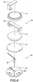
- the present invention provides a luminous bottle stopper 1 including a light guide body 10, a light emitting module 20, a power module 30, a stopper cover 40 and a flexible sleeve 50.
- the light emitting module 20 and the power module 30 are disposed in the light guide body 10.
- the stopper cover 40 and the flexible sleeve 50 are combined on two sides of the light guide body 10 separately as to constitute the luminous bottle stopper 1. More details of the luminous bottle stopper 1 are descripted as follows.
- the light guide body 10 is made of light transmitting material.
- the light guide body 10 includes a light guide seat 11 and a light guide column 12 connected with the light guide seat 11, and the light guide seat 11 has an accommodating space 110.
- the light guide seat 11 and the light guide column 12 are formed as an integral body.
- an outer peripheral surface of the light guide column 12 has formed a light guide rib 121 shaped in helical.
- the arrangement of the light guide rib 121 can facilitate a uniform and soft light conducting for a better luminous efficiency.
- the light guide column 12 also has textures, printed veins or carved light guide lines 120 as to enhance the lighting effects.
- the light guide seat 11 has a light guide angle 113 neighboring a side of the light guide column 12, and the deposition of the light guide angle 113 can transmit the light emitted from the light emitting module 20 to the light guide column 12. It is worthy of notice that an inner wall of the light guide seat 11 has further provided with a reflecting layer 114, and the deposition of the reflecting layer 114 can increase the luminous efficiency.
- the light emitting module 20 is installed in the accommodating space 110 of the light guide seat 11.
- the light emitting module 20 includes a circuit board 21 and a light emitting element 22 electrically connected with the circuit board 21.
- the light emitting element 22 is, but not limited to, a light emitting diode (LED).
- the power module 30 is installed in the accommodating space 110 of the light guide seat 11 and located in a lateral side of the light emitting module 20.
- the power module 30 is the power source of the light emitting module 20 including at least one battery 31 and a conduct element 32 electrically connected with the at least one battery 31, and the conduct element 32 is electrically connected with the circuit board 21.
- the battery 31 can be electrically to the light emitting element 22 through the circuit board 21 and provide power to the light emitting element 22 for the lighting.
- the conduct element 32 is a conductive sheet, however, in real practice, the conduct element 32 can be a wire and so on.
- the battery 31 may be provided as a dry battery, a lithium battery, a button battery, or a rechargeable battery.
- the power module 30 can further include a touch switch. The touch switch is electrically connected with the circuit board 21 and can be disposed in the stopper cover 40 for controlling the light emitting element 22,
- the stopper cover 40 is coupled to the light guide seat 11 and sealed the accommodating space 110.
- the flexible sleeve 50 is made of light transmitting material and sleeved on the light guide column 12.
- the flexible sleeve 50 comprises a holding portion 51 and a revolving fasten portion 52.
- the holding portion 51 is abutted upon a bottom of the light guide seat 11, and an outer peripheral surface of the revolving fasten portion 52 has formed a seal rib 521 shaped in a helical.
- an outer peripheral surface of the light guide column 12 of the light guide body 10 has formed a light guide rib 121.
- the flexible sleeve 50 has formed a light guide slot 501 shaped in helical corresponding to the light guide rib 121, and the light guide rib 121 of the light guide column 12 is located in the light guide slot 501.
- the luminous bottle stopper 1 further includes a seal ring 60 disposed between the light guide seat 11 and the stopper cover 40 as to enhance the leak tightness therebetween.
- the light guide seat 11 has formed an annular groove 111 in the accommodating space 110
- the stopper cover 40 has a pressing plate 401 disposed correspondingly above the annular groove 111. Accordingly, the seal ring 60 is disposed in the annular groove 111 and pressed by the pressing plate 401; thereby, external air or moisture can be prevented from entering the accommodating space 110.
- an inner wall of the light guide seat 11 are formed a plurality of resist ribs 112 at a bottom of the annular groove 111, and the resist ribs 112 are tightly attached to the periphery of the stopper cover 40 as to fix the stopper cover 40 on the light guide seat 11.
- the stopper cover 40 includes a cover plate 41 and a plurality of support plate 42 connected with the cover plate 41, and the resist ribs 112 abut against an outer side of the support plate 42.
- the cover plate 41 has a notch 410, and the cover plate 41 has formed a positioning portion 411 in the notch 410 (in the present embodiment, a position groove is configured by a pair of ribs).
- the luminous bottle stopper 1 of the present invention is movable by exerting on the positioning portion 411 and rotating it.
- the light emitting module 20 further includes a bearing seat 23.
- the bearing seat 23 carries the circuit board 21 and has a through hole 230 corresponding to the light emitting element 22. Moreover, one part of the light emitting element 22 is located in the through hole 230 and another part thereof is located in the light guide seat 11.
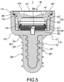
- FIG. 5 and FIG. 6 depict a cross sectional view of the assembly of the luminous bottle stopper of the present invention and a lighting schematic view of the luminous bottle stopper of the present invention.
- the air tightness between the stopper cover 40 and the light guide body 10 can be achieved through the seal ring 60 so that the light emitting module 20 and the power module 30 inside the light guide seat 11 will have good electricity characteristics.
- one part of the light emitting element 22 is located in the light guide seat 11, hence the light emitted from the light emitting element 22 will be transmitted to the light guide seat 11 and the light guide column 12, and then the light will be transmitted to outside through the light guide seat 11 and the light guide column 12.
- the luminous bottle stopper 1 is used to be plugged in a mouth 2 of a bottle.
- the flexible sleeve 50 of the luminous bottle stopper 1 is sleeved on the light guide column 12 and can be plugged in the mouth 2 of the bottle.
- the light guide body 10 and the flexible sleeve 50 are made of light transmitting material.
- the light emitted from the light emitting element 22 will be transmitted to the light guide seat 11 and the light guide column 12, and then the light will be transmitted to the outside through the light guide seat 11 and the light guide column 12.
- the light emitted to the light guide column 12 will pass through the flexible sleeve 50 and the mouth 2 of the bottle so that the luminous bottle stopper 1 and areas surrounding the mouth 2 of the bottle both have lighting effects.
- the light guide ribs 121 of the light guide column 12 can facilitate a uniform and soft light conducting for a better luminous efficiency and enhance the overall appearance, creativity and uniqueness of the present invention.
Landscapes
- Engineering & Computer Science (AREA)
- Mechanical Engineering (AREA)
- Non-Portable Lighting Devices Or Systems Thereof (AREA)
- Arrangement Of Elements, Cooling, Sealing, Or The Like Of Lighting Devices (AREA)
Claims (9)
- Ein leuchtender Flaschenverschluss zum Einstecken in eine Flaschenmündung (2), bestehend aus:einen Lichtleiterkörper (10) aus lichtdurchlässigem Material, wobei der Lichtleiterkörper (10) einen Lichtleitersitz (11) und eine Lichtleitersäule (12), die mit dem Lichtleitersitz (11) verbunden ist, aufweist und der Lichtleitersitz (11) einen Aufnahmeraum (110) hat;ein lichtemittierendes Modul (20), das in dem Aufnahmeraum (110) installiert ist, wobei das lichtemittierende Modul (20) eine Leiterplatte (21) und ein lichtemittierendes Element (22) enthält, das elektrisch mit der Leiterplatte (21) verbunden ist;ein Leistungsmodul (30), das in dem Aufnahmeraum (110) installiert ist, wobei das Leistungsmodul (30) mindestens eine Batterie (31) und ein Leitelement (32) umfasst, das elektrisch mit der mindestens einen Batterie (31) verbunden ist;eine Stopperabdeckung (40), die mit dem Lichtleitersitz (11) kombiniert ist und den Aufnahmeraum (110) abdichtet; undeine biegsame Hülse (50) aus lichtdurchlässigem Material, wobei die biegsame Hülse (50) auf die Lichtleitersäule (12) aufgeschoben ist und in die Mündung (2) der Flasche eingesteckt werden kann, dadurch gekennzeichnet, dass eine äußere Umfangsfläche der Lichtleitersäule (12) mit einer schraubenförmig geformten Lichtleiterrippe (121) ausgebildet ist.
- Der leuchtende Flaschenverschluss nach Anspruch 1, wobei eine äußere Umfangsfläche der Lichtleitersäule (12) Texturen, aufgedruckte Adern oder eingeritzte Lichtleitlinien (120) aufweist.
- Der leuchtende Flaschenverschluss nach einem der Ansprüche 1 bis 2, ferner umfassend einen Dichtungsring (60), wobei der Dichtungsring (60) zwischen dem Lichtleitersitz (11) und dem Stopperabdeckung (40) angeordnet ist; der Lichtleitersitz (11) in dem Aufnahmeraum (110) eine Ringnut (111) ausgebildet ist und der Stopperabdeckung (40) eine entsprechend oberhalb der Ringnut (111) angeordnete Pressplatte (401) aufweist; der Dichtungsring (60) in der Ringnut (111) angeordnet und durch die Pressplatte (401) gepresst ist.
- Der leuchtende Flaschenverschluss nach einem der Ansprüche 1 bis 3, wobei der Lichtleitersitz (11) einen Lichtleitwinkel (113) aufweist, der an eine Seite der Lichtleitersäule (12) angrenzt; eine Innenwand des Lichtleitersitzes (11) ist ferner mit einer reflektierenden Schicht (114) versehen.
- Der leuchtende Flaschenverschluss nach Anspruch 3 oder 4, wobei an einer Innenwand des Lichtleitersitzes (11) eine Vielzahl von Widerstandsrippen (112) an einem Boden der ringförmigen Nut (111) ausgebildet ist und die Widerstandsrippen (112) fest an der Stopperabdeckung (40) angebracht sind; die Stopperabdeckung (40) eine Abdeckplatte (41) und eine Vielzahl von mit der Abdeckplatte (41) verbundenen Stützplatten (42) umfasst und die Widerstandsrippen (112) an einer Außenseite der Stützplatte (42) anliegen.
- Der leuchtende Flaschenverschluss nach Anspruch 5, wobei die Abdeckplatte (41) eine Kerbe (410) aufweist und die Abdeckplatte (41) einen Positionierungsabschnitt (411) in der Kerbe (410) aufweist; der leuchtende Flaschenverschluss (1) ist relativ zur Flaschenmündung (2) beweglich, indem er auf den Positionierungsabschnitt (411) drückt.
- Der leuchtende Flaschenverschluss nach einem der Ansprüche 1 bis 6, wobei das lichtemittierende Modul (20) ferner einen Lagersitz (23) aufweist und der Lagersitz (23) die Leiterplatte (21) trägt und ein Durchgangsloch (230) aufweist, das dem lichtemittierenden Element (22) entspricht; wobei ein Teil des lichtemittierenden Elements (22) in dem Durchgangsloch (230) und ein anderer Teil davon in dem Lichtleitersitz (11) angeordnet ist.
- Der leuchtende Flaschenverschluss nach einem der Ansprüche 1 bis 7, wobei die flexible Hülse (50) einen Halteabschnitt (51) und einen Drehbefestigungsabschnitt (52) aufweist; der Halteabschnitt (51) liegt an einem Boden des Lichtleitersitzes (11) an, und eine äußere Umfangsfläche des Drehbefestigungsabschnitts (52) ist mit einer schraubenförmig geformten Dichtungsrippe (521) versehen.
- Der leuchtende Flaschenverschluss nach einem der Ansprüche 1 bis 8, wobei die flexible Hülse (50) einen schraubenförmigen Lichtleitschlitz (501) aufweist, der mit der Lichtleitrippe (121) korrespondiert, und die Lichtleitrippe (121) in dem Lichtleitschlitz (501) angeordnet ist.
Priority Applications (1)
| Application Number | Priority Date | Filing Date | Title |
|---|---|---|---|
| EP17185393.0A EP3441320B1 (de) | 2017-08-08 | 2017-08-08 | Leuchtende flaschenstopfen |
Applications Claiming Priority (1)
| Application Number | Priority Date | Filing Date | Title |
|---|---|---|---|
| EP17185393.0A EP3441320B1 (de) | 2017-08-08 | 2017-08-08 | Leuchtende flaschenstopfen |
Publications (2)
| Publication Number | Publication Date |
|---|---|
| EP3441320A1 EP3441320A1 (de) | 2019-02-13 |
| EP3441320B1 true EP3441320B1 (de) | 2022-03-16 |
Family
ID=59592864
Family Applications (1)
| Application Number | Title | Priority Date | Filing Date |
|---|---|---|---|
| EP17185393.0A Not-in-force EP3441320B1 (de) | 2017-08-08 | 2017-08-08 | Leuchtende flaschenstopfen |
Country Status (1)
| Country | Link |
|---|---|
| EP (1) | EP3441320B1 (de) |
Families Citing this family (14)
| Publication number | Priority date | Publication date | Assignee | Title |
|---|---|---|---|---|
| US10093460B2 (en) | 2015-08-14 | 2018-10-09 | Yeti Coolers, Llc | Container with magnetic cap |
| USD787893S1 (en) | 2015-11-20 | 2017-05-30 | Yeti Coolers, Llc | Jug |
| US10959552B2 (en) | 2016-10-17 | 2021-03-30 | Yeti Coolers, Llc | Container and method of forming a container |
| US11034505B2 (en) | 2016-10-17 | 2021-06-15 | Yeti Coolers, Llc | Container and method of forming a container |
| US10959553B2 (en) | 2016-10-17 | 2021-03-30 | Yeti Coolers, Llc | Container and method of forming a container |
| EP3525638B1 (de) | 2016-10-17 | 2021-11-17 | YETI Coolers, LLC | Isolierbehälter mit magnetischem deckel |
| USD860716S1 (en) | 2017-03-27 | 2019-09-24 | Yeti Coolers, Llc | Container lid |
| USD896572S1 (en) | 2018-08-20 | 2020-09-22 | Yeti Coolers, Llc | Container lid |
| USD871133S1 (en) | 2018-10-17 | 2019-12-31 | Yeti Coolers, Llc | Lid |
| USD883738S1 (en) | 2018-10-17 | 2020-05-12 | Yeti Coolers, Llc | Lid |
| USD883737S1 (en) | 2018-10-17 | 2020-05-12 | Yeti Coolers, Llc | Lid |
| USD897151S1 (en) | 2018-10-17 | 2020-09-29 | Yeti Coolers, Llc | Lid |
| CN110466877B (zh) * | 2019-08-21 | 2024-04-26 | 惠州康耐特电热制品有限公司 | 一种可充电的usb酒瓶塞灯 |
| US12589919B2 (en) | 2023-06-07 | 2026-03-31 | Yeti Coolers, Llc | Lid assembly for beverage container |
Family Cites Families (5)
| Publication number | Priority date | Publication date | Assignee | Title |
|---|---|---|---|---|
| DE202008001443U1 (de) * | 2008-02-01 | 2008-08-14 | Tilger, Erik | Leuchtender Flaschenverschluss |
| GB2464524A (en) * | 2008-10-20 | 2010-04-21 | Chin-Sheng Yang | Aqua lamp bottle stopper |
| JP5561685B1 (ja) * | 2013-06-03 | 2014-07-30 | 株式会社キューブエッグ | ライト付きコルク |
| FR3008961A1 (fr) * | 2013-07-29 | 2015-01-30 | Dominique Bourin | Bouchon lumineux et bouteille fermee par un tel bouchon |
| US11001424B2 (en) * | 2014-02-06 | 2021-05-11 | Zero Oxygen Solutions, Inc. | Reusable closure |
-
2017
- 2017-08-08 EP EP17185393.0A patent/EP3441320B1/de not_active Not-in-force
Also Published As
| Publication number | Publication date |
|---|---|
| EP3441320A1 (de) | 2019-02-13 |
Similar Documents
| Publication | Publication Date | Title |
|---|---|---|
| EP3441320B1 (de) | Leuchtende flaschenstopfen | |
| US9975675B1 (en) | Luminous bottle stopper | |
| US7740368B2 (en) | Cap with a light emitting diode (LED) for illuminating a beverage container | |
| US10112766B1 (en) | Intelligent insulation cup | |
| US10401019B2 (en) | Container with touch sensitive function | |
| US7384164B2 (en) | Illuminated liquid dispensing container | |
| US20180327154A1 (en) | Bottle light | |
| US9090381B2 (en) | Illuminated bottle stopper | |
| US20160265730A1 (en) | Lighting attachment | |
| CA2975215C (en) | Luminous bottle stopper | |
| US11112106B1 (en) | Cordless lamp | |
| AU2015203269A1 (en) | Handy pump | |
| JP5354194B2 (ja) | Ledランプ | |
| JP5561685B1 (ja) | ライト付きコルク | |
| US5992319A (en) | Seal | |
| US11221132B1 (en) | Cordless lamp | |
| CN206624169U (zh) | 发光瓶塞 | |
| KR20180103249A (ko) | Led를 이용한 위조방지 캡 | |
| JP3213210U (ja) | 発光栓 | |
| EP4023931B1 (de) | Schnurlose lampe | |
| EP4023930B1 (de) | Schnurlose lampe | |
| US10334932B1 (en) | Lightening cosmetic container | |
| US20160245463A1 (en) | Multi-refraction led lamp | |
| CN223516807U (zh) | 理疗仪和化妆品器具 | |
| CN213154598U (zh) | 一种内置多光源的唇膏管 |
Legal Events
| Date | Code | Title | Description |
|---|---|---|---|
| PUAI | Public reference made under article 153(3) epc to a published international application that has entered the european phase |
Free format text: ORIGINAL CODE: 0009012 |
|
| STAA | Information on the status of an ep patent application or granted ep patent |
Free format text: STATUS: REQUEST FOR EXAMINATION WAS MADE |
|
| 17P | Request for examination filed |
Effective date: 20180719 |
|
| AK | Designated contracting states |
Kind code of ref document: A1 Designated state(s): AL AT BE BG CH CY CZ DE DK EE ES FI FR GB GR HR HU IE IS IT LI LT LU LV MC MK MT NL NO PL PT RO RS SE SI SK SM TR |
|
| AX | Request for extension of the european patent |
Extension state: BA ME |
|
| GRAP | Despatch of communication of intention to grant a patent |
Free format text: ORIGINAL CODE: EPIDOSNIGR1 |
|
| STAA | Information on the status of an ep patent application or granted ep patent |
Free format text: STATUS: GRANT OF PATENT IS INTENDED |
|
| INTG | Intention to grant announced |
Effective date: 20211005 |
|
| GRAS | Grant fee paid |
Free format text: ORIGINAL CODE: EPIDOSNIGR3 |
|
| GRAA | (expected) grant |
Free format text: ORIGINAL CODE: 0009210 |
|
| STAA | Information on the status of an ep patent application or granted ep patent |
Free format text: STATUS: THE PATENT HAS BEEN GRANTED |
|
| AK | Designated contracting states |
Kind code of ref document: B1 Designated state(s): AL AT BE BG CH CY CZ DE DK EE ES FI FR GB GR HR HU IE IS IT LI LT LU LV MC MK MT NL NO PL PT RO RS SE SI SK SM TR |
|
| REG | Reference to a national code |
Ref country code: GB Ref legal event code: FG4D |
|
| REG | Reference to a national code |
Ref country code: CH Ref legal event code: EP |
|
| REG | Reference to a national code |
Ref country code: DE Ref legal event code: R096 Ref document number: 602017054580 Country of ref document: DE |
|
| REG | Reference to a national code |
Ref country code: IE Ref legal event code: FG4D |
|
| REG | Reference to a national code |
Ref country code: AT Ref legal event code: REF Ref document number: 1475728 Country of ref document: AT Kind code of ref document: T Effective date: 20220415 |
|
| REG | Reference to a national code |
Ref country code: LT Ref legal event code: MG9D |
|
| PG25 | Lapsed in a contracting state [announced via postgrant information from national office to epo] |
Ref country code: SE Free format text: LAPSE BECAUSE OF FAILURE TO SUBMIT A TRANSLATION OF THE DESCRIPTION OR TO PAY THE FEE WITHIN THE PRESCRIBED TIME-LIMIT Effective date: 20220316 Ref country code: RS Free format text: LAPSE BECAUSE OF FAILURE TO SUBMIT A TRANSLATION OF THE DESCRIPTION OR TO PAY THE FEE WITHIN THE PRESCRIBED TIME-LIMIT Effective date: 20220316 Ref country code: NO Free format text: LAPSE BECAUSE OF FAILURE TO SUBMIT A TRANSLATION OF THE DESCRIPTION OR TO PAY THE FEE WITHIN THE PRESCRIBED TIME-LIMIT Effective date: 20220616 Ref country code: LT Free format text: LAPSE BECAUSE OF FAILURE TO SUBMIT A TRANSLATION OF THE DESCRIPTION OR TO PAY THE FEE WITHIN THE PRESCRIBED TIME-LIMIT Effective date: 20220316 Ref country code: HR Free format text: LAPSE BECAUSE OF FAILURE TO SUBMIT A TRANSLATION OF THE DESCRIPTION OR TO PAY THE FEE WITHIN THE PRESCRIBED TIME-LIMIT Effective date: 20220316 Ref country code: BG Free format text: LAPSE BECAUSE OF FAILURE TO SUBMIT A TRANSLATION OF THE DESCRIPTION OR TO PAY THE FEE WITHIN THE PRESCRIBED TIME-LIMIT Effective date: 20220616 |
|
| REG | Reference to a national code |
Ref country code: AT Ref legal event code: MK05 Ref document number: 1475728 Country of ref document: AT Kind code of ref document: T Effective date: 20220316 |
|
| PG25 | Lapsed in a contracting state [announced via postgrant information from national office to epo] |
Ref country code: LV Free format text: LAPSE BECAUSE OF FAILURE TO SUBMIT A TRANSLATION OF THE DESCRIPTION OR TO PAY THE FEE WITHIN THE PRESCRIBED TIME-LIMIT Effective date: 20220316 Ref country code: FI Free format text: LAPSE BECAUSE OF FAILURE TO SUBMIT A TRANSLATION OF THE DESCRIPTION OR TO PAY THE FEE WITHIN THE PRESCRIBED TIME-LIMIT Effective date: 20220316 |
|
| PG25 | Lapsed in a contracting state [announced via postgrant information from national office to epo] |
Ref country code: NL Free format text: LAPSE BECAUSE OF FAILURE TO SUBMIT A TRANSLATION OF THE DESCRIPTION OR TO PAY THE FEE WITHIN THE PRESCRIBED TIME-LIMIT Effective date: 20220316 |
|
| PG25 | Lapsed in a contracting state [announced via postgrant information from national office to epo] |
Ref country code: SM Free format text: LAPSE BECAUSE OF FAILURE TO SUBMIT A TRANSLATION OF THE DESCRIPTION OR TO PAY THE FEE WITHIN THE PRESCRIBED TIME-LIMIT Effective date: 20220316 Ref country code: SK Free format text: LAPSE BECAUSE OF FAILURE TO SUBMIT A TRANSLATION OF THE DESCRIPTION OR TO PAY THE FEE WITHIN THE PRESCRIBED TIME-LIMIT Effective date: 20220316 Ref country code: RO Free format text: LAPSE BECAUSE OF FAILURE TO SUBMIT A TRANSLATION OF THE DESCRIPTION OR TO PAY THE FEE WITHIN THE PRESCRIBED TIME-LIMIT Effective date: 20220316 Ref country code: PT Free format text: LAPSE BECAUSE OF FAILURE TO SUBMIT A TRANSLATION OF THE DESCRIPTION OR TO PAY THE FEE WITHIN THE PRESCRIBED TIME-LIMIT Effective date: 20220718 Ref country code: ES Free format text: LAPSE BECAUSE OF FAILURE TO SUBMIT A TRANSLATION OF THE DESCRIPTION OR TO PAY THE FEE WITHIN THE PRESCRIBED TIME-LIMIT Effective date: 20220316 Ref country code: EE Free format text: LAPSE BECAUSE OF FAILURE TO SUBMIT A TRANSLATION OF THE DESCRIPTION OR TO PAY THE FEE WITHIN THE PRESCRIBED TIME-LIMIT Effective date: 20220316 Ref country code: CZ Free format text: LAPSE BECAUSE OF FAILURE TO SUBMIT A TRANSLATION OF THE DESCRIPTION OR TO PAY THE FEE WITHIN THE PRESCRIBED TIME-LIMIT Effective date: 20220316 Ref country code: AT Free format text: LAPSE BECAUSE OF FAILURE TO SUBMIT A TRANSLATION OF THE DESCRIPTION OR TO PAY THE FEE WITHIN THE PRESCRIBED TIME-LIMIT Effective date: 20220316 |
|
| PGFP | Annual fee paid to national office [announced via postgrant information from national office to epo] |
Ref country code: IT Payment date: 20220730 Year of fee payment: 6 Ref country code: GB Payment date: 20220808 Year of fee payment: 6 Ref country code: DE Payment date: 20220831 Year of fee payment: 6 |
|
| PG25 | Lapsed in a contracting state [announced via postgrant information from national office to epo] |
Ref country code: PL Free format text: LAPSE BECAUSE OF FAILURE TO SUBMIT A TRANSLATION OF THE DESCRIPTION OR TO PAY THE FEE WITHIN THE PRESCRIBED TIME-LIMIT Effective date: 20220316 Ref country code: IS Free format text: LAPSE BECAUSE OF FAILURE TO SUBMIT A TRANSLATION OF THE DESCRIPTION OR TO PAY THE FEE WITHIN THE PRESCRIBED TIME-LIMIT Effective date: 20220716 Ref country code: AL Free format text: LAPSE BECAUSE OF FAILURE TO SUBMIT A TRANSLATION OF THE DESCRIPTION OR TO PAY THE FEE WITHIN THE PRESCRIBED TIME-LIMIT Effective date: 20220316 |
|
| PGFP | Annual fee paid to national office [announced via postgrant information from national office to epo] |
Ref country code: FR Payment date: 20220729 Year of fee payment: 6 |
|
| REG | Reference to a national code |
Ref country code: DE Ref legal event code: R097 Ref document number: 602017054580 Country of ref document: DE |
|
| PLBE | No opposition filed within time limit |
Free format text: ORIGINAL CODE: 0009261 |
|
| STAA | Information on the status of an ep patent application or granted ep patent |
Free format text: STATUS: NO OPPOSITION FILED WITHIN TIME LIMIT |
|
| PG25 | Lapsed in a contracting state [announced via postgrant information from national office to epo] |
Ref country code: DK Free format text: LAPSE BECAUSE OF FAILURE TO SUBMIT A TRANSLATION OF THE DESCRIPTION OR TO PAY THE FEE WITHIN THE PRESCRIBED TIME-LIMIT Effective date: 20220316 |
|
| 26N | No opposition filed |
Effective date: 20221219 |
|
| PG25 | Lapsed in a contracting state [announced via postgrant information from national office to epo] |
Ref country code: SI Free format text: LAPSE BECAUSE OF FAILURE TO SUBMIT A TRANSLATION OF THE DESCRIPTION OR TO PAY THE FEE WITHIN THE PRESCRIBED TIME-LIMIT Effective date: 20220316 |
|
| PG25 | Lapsed in a contracting state [announced via postgrant information from national office to epo] |
Ref country code: MC Free format text: LAPSE BECAUSE OF FAILURE TO SUBMIT A TRANSLATION OF THE DESCRIPTION OR TO PAY THE FEE WITHIN THE PRESCRIBED TIME-LIMIT Effective date: 20220316 |
|
| REG | Reference to a national code |
Ref country code: CH Ref legal event code: PL |
|
| PG25 | Lapsed in a contracting state [announced via postgrant information from national office to epo] |
Ref country code: LU Free format text: LAPSE BECAUSE OF NON-PAYMENT OF DUE FEES Effective date: 20220808 Ref country code: LI Free format text: LAPSE BECAUSE OF NON-PAYMENT OF DUE FEES Effective date: 20220831 Ref country code: CH Free format text: LAPSE BECAUSE OF NON-PAYMENT OF DUE FEES Effective date: 20220831 |
|
| REG | Reference to a national code |
Ref country code: BE Ref legal event code: MM Effective date: 20220831 |
|
| PG25 | Lapsed in a contracting state [announced via postgrant information from national office to epo] |
Ref country code: IE Free format text: LAPSE BECAUSE OF NON-PAYMENT OF DUE FEES Effective date: 20220808 |
|
| PG25 | Lapsed in a contracting state [announced via postgrant information from national office to epo] |
Ref country code: BE Free format text: LAPSE BECAUSE OF NON-PAYMENT OF DUE FEES Effective date: 20220831 |
|
| REG | Reference to a national code |
Ref country code: DE Ref legal event code: R119 Ref document number: 602017054580 Country of ref document: DE |
|
| PG25 | Lapsed in a contracting state [announced via postgrant information from national office to epo] |
Ref country code: HU Free format text: LAPSE BECAUSE OF FAILURE TO SUBMIT A TRANSLATION OF THE DESCRIPTION OR TO PAY THE FEE WITHIN THE PRESCRIBED TIME-LIMIT; INVALID AB INITIO Effective date: 20170808 |
|
| GBPC | Gb: european patent ceased through non-payment of renewal fee |
Effective date: 20230808 |
|
| PG25 | Lapsed in a contracting state [announced via postgrant information from national office to epo] |
Ref country code: CY Free format text: LAPSE BECAUSE OF FAILURE TO SUBMIT A TRANSLATION OF THE DESCRIPTION OR TO PAY THE FEE WITHIN THE PRESCRIBED TIME-LIMIT Effective date: 20220316 |
|
| PG25 | Lapsed in a contracting state [announced via postgrant information from national office to epo] |
Ref country code: MK Free format text: LAPSE BECAUSE OF FAILURE TO SUBMIT A TRANSLATION OF THE DESCRIPTION OR TO PAY THE FEE WITHIN THE PRESCRIBED TIME-LIMIT Effective date: 20220316 |
|
| PG25 | Lapsed in a contracting state [announced via postgrant information from national office to epo] |
Ref country code: TR Free format text: LAPSE BECAUSE OF FAILURE TO SUBMIT A TRANSLATION OF THE DESCRIPTION OR TO PAY THE FEE WITHIN THE PRESCRIBED TIME-LIMIT Effective date: 20220316 |
|
| PG25 | Lapsed in a contracting state [announced via postgrant information from national office to epo] |
Ref country code: GB Free format text: LAPSE BECAUSE OF NON-PAYMENT OF DUE FEES Effective date: 20230808 |
|
| PG25 | Lapsed in a contracting state [announced via postgrant information from national office to epo] |
Ref country code: IT Free format text: LAPSE BECAUSE OF NON-PAYMENT OF DUE FEES Effective date: 20230808 Ref country code: GB Free format text: LAPSE BECAUSE OF NON-PAYMENT OF DUE FEES Effective date: 20230808 Ref country code: FR Free format text: LAPSE BECAUSE OF NON-PAYMENT OF DUE FEES Effective date: 20230831 Ref country code: DE Free format text: LAPSE BECAUSE OF NON-PAYMENT OF DUE FEES Effective date: 20240301 |
|
| PG25 | Lapsed in a contracting state [announced via postgrant information from national office to epo] |
Ref country code: MT Free format text: LAPSE BECAUSE OF FAILURE TO SUBMIT A TRANSLATION OF THE DESCRIPTION OR TO PAY THE FEE WITHIN THE PRESCRIBED TIME-LIMIT Effective date: 20220316 |
|
| PG25 | Lapsed in a contracting state [announced via postgrant information from national office to epo] |
Ref country code: GR Free format text: LAPSE BECAUSE OF NON-PAYMENT OF DUE FEES Effective date: 20220316 |
|
| PG25 | Lapsed in a contracting state [announced via postgrant information from national office to epo] |
Ref country code: GR Free format text: LAPSE BECAUSE OF NON-PAYMENT OF DUE FEES Effective date: 20220316 |