EP4023931B1 - Schnurlose lampe - Google Patents
Schnurlose lampe Download PDFInfo
- Publication number
- EP4023931B1 EP4023931B1 EP20217890.1A EP20217890A EP4023931B1 EP 4023931 B1 EP4023931 B1 EP 4023931B1 EP 20217890 A EP20217890 A EP 20217890A EP 4023931 B1 EP4023931 B1 EP 4023931B1
- Authority
- EP
- European Patent Office
- Prior art keywords
- housing
- charge
- circuit board
- discharge
- lamp
- Prior art date
- Legal status (The legal status is an assumption and is not a legal conclusion. Google has not performed a legal analysis and makes no representation as to the accuracy of the status listed.)
- Active
Links
Images



Classifications
-
- F—MECHANICAL ENGINEERING; LIGHTING; HEATING; WEAPONS; BLASTING
- F21—LIGHTING
- F21L—LIGHTING DEVICES OR SYSTEMS THEREOF, BEING PORTABLE OR SPECIALLY ADAPTED FOR TRANSPORTATION
- F21L4/00—Electric lighting devices with self-contained electric batteries or cells
- F21L4/02—Electric lighting devices with self-contained electric batteries or cells characterised by the provision of two or more light sources
-
- F—MECHANICAL ENGINEERING; LIGHTING; HEATING; WEAPONS; BLASTING
- F21—LIGHTING
- F21V—FUNCTIONAL FEATURES OR DETAILS OF LIGHTING DEVICES OR SYSTEMS THEREOF; STRUCTURAL COMBINATIONS OF LIGHTING DEVICES WITH OTHER ARTICLES, NOT OTHERWISE PROVIDED FOR
- F21V23/00—Arrangement of electric circuit elements in or on lighting devices
- F21V23/04—Arrangement of electric circuit elements in or on lighting devices the elements being switches
- F21V23/0414—Arrangement of electric circuit elements in or on lighting devices the elements being switches specially adapted to be used with portable lighting devices
-
- F—MECHANICAL ENGINEERING; LIGHTING; HEATING; WEAPONS; BLASTING
- F21—LIGHTING
- F21V—FUNCTIONAL FEATURES OR DETAILS OF LIGHTING DEVICES OR SYSTEMS THEREOF; STRUCTURAL COMBINATIONS OF LIGHTING DEVICES WITH OTHER ARTICLES, NOT OTHERWISE PROVIDED FOR
- F21V31/00—Gas-tight or water-tight arrangements
- F21V31/005—Sealing arrangements therefor
-
- F—MECHANICAL ENGINEERING; LIGHTING; HEATING; WEAPONS; BLASTING
- F21—LIGHTING
- F21L—LIGHTING DEVICES OR SYSTEMS THEREOF, BEING PORTABLE OR SPECIALLY ADAPTED FOR TRANSPORTATION
- F21L4/00—Electric lighting devices with self-contained electric batteries or cells
- F21L4/08—Electric lighting devices with self-contained electric batteries or cells characterised by means for in situ recharging of the batteries or cells
-
- F—MECHANICAL ENGINEERING; LIGHTING; HEATING; WEAPONS; BLASTING
- F21—LIGHTING
- F21V—FUNCTIONAL FEATURES OR DETAILS OF LIGHTING DEVICES OR SYSTEMS THEREOF; STRUCTURAL COMBINATIONS OF LIGHTING DEVICES WITH OTHER ARTICLES, NOT OTHERWISE PROVIDED FOR
- F21V17/00—Fastening of component parts of lighting devices, e.g. shades, globes, refractors, reflectors, filters, screens, grids or protective cages
- F21V17/10—Fastening of component parts of lighting devices, e.g. shades, globes, refractors, reflectors, filters, screens, grids or protective cages characterised by specific fastening means or way of fastening
- F21V17/16—Fastening of component parts of lighting devices, e.g. shades, globes, refractors, reflectors, filters, screens, grids or protective cages characterised by specific fastening means or way of fastening by deformation of parts; Snap action mounting
- F21V17/164—Fastening of component parts of lighting devices, e.g. shades, globes, refractors, reflectors, filters, screens, grids or protective cages characterised by specific fastening means or way of fastening by deformation of parts; Snap action mounting the parts being subjected to bending, e.g. snap joints
-
- F—MECHANICAL ENGINEERING; LIGHTING; HEATING; WEAPONS; BLASTING
- F21—LIGHTING
- F21V—FUNCTIONAL FEATURES OR DETAILS OF LIGHTING DEVICES OR SYSTEMS THEREOF; STRUCTURAL COMBINATIONS OF LIGHTING DEVICES WITH OTHER ARTICLES, NOT OTHERWISE PROVIDED FOR
- F21V19/00—Fastening of light sources or lamp holders
- F21V19/001—Fastening of light sources or lamp holders the light sources being semiconductors devices, e.g. LEDs
- F21V19/003—Fastening of light source holders, e.g. of circuit boards or substrates holding light sources
- F21V19/0035—Fastening of light source holders, e.g. of circuit boards or substrates holding light sources the fastening means being capable of simultaneously attaching of an other part, e.g. a housing portion or an optical component
-
- F—MECHANICAL ENGINEERING; LIGHTING; HEATING; WEAPONS; BLASTING
- F21—LIGHTING
- F21V—FUNCTIONAL FEATURES OR DETAILS OF LIGHTING DEVICES OR SYSTEMS THEREOF; STRUCTURAL COMBINATIONS OF LIGHTING DEVICES WITH OTHER ARTICLES, NOT OTHERWISE PROVIDED FOR
- F21V21/00—Supporting, suspending, or attaching arrangements for lighting devices; Hand grips
- F21V21/08—Devices for easy attachment to any desired place, e.g. clip, clamp, magnet
- F21V21/088—Clips; Clamps
- F21V21/0885—Clips; Clamps for portable lighting devices
-
- F—MECHANICAL ENGINEERING; LIGHTING; HEATING; WEAPONS; BLASTING
- F21—LIGHTING
- F21V—FUNCTIONAL FEATURES OR DETAILS OF LIGHTING DEVICES OR SYSTEMS THEREOF; STRUCTURAL COMBINATIONS OF LIGHTING DEVICES WITH OTHER ARTICLES, NOT OTHERWISE PROVIDED FOR
- F21V23/00—Arrangement of electric circuit elements in or on lighting devices
- F21V23/06—Arrangement of electric circuit elements in or on lighting devices the elements being coupling devices, e.g. connectors
-
- F—MECHANICAL ENGINEERING; LIGHTING; HEATING; WEAPONS; BLASTING
- F21—LIGHTING
- F21Y—INDEXING SCHEME ASSOCIATED WITH SUBCLASSES F21K, F21L, F21S and F21V, RELATING TO THE FORM OR THE KIND OF THE LIGHT SOURCES OR OF THE COLOUR OF THE LIGHT EMITTED
- F21Y2115/00—Light-generating elements of semiconductor light sources
- F21Y2115/10—Light-emitting diodes [LED]
-
- H—ELECTRICITY
- H01—ELECTRIC ELEMENTS
- H01H—ELECTRIC SWITCHES; RELAYS; SELECTORS; EMERGENCY PROTECTIVE DEVICES
- H01H13/00—Switches having rectilinearly-movable operating part or parts adapted for pushing or pulling in one direction only, e.g. push-button switch
- H01H13/02—Details
- H01H13/04—Cases; Covers
- H01H13/06—Dustproof, splashproof, drip-proof, waterproof or flameproof casings
-
- H—ELECTRICITY
- H01—ELECTRIC ELEMENTS
- H01H—ELECTRIC SWITCHES; RELAYS; SELECTORS; EMERGENCY PROTECTIVE DEVICES
- H01H2223/00—Casings
- H01H2223/002—Casings sealed
Definitions
- the present disclosure relates to the technical field of a lighting device, and more specifically, to a cordless lamp.
- a tact switch for a cordless lamp is typically connected to an external rubber button. Because the tact switch is relatively sensitive, the cordless lamp may be lit up by gently touching the rubber button. As such, if the rubber button is accidentally touched during the product handling and transportation process, the cordless lamp may remain in the lit-up state the whole time, resulting in loss of the built-in power of the cordless lamp, thus affecting the quality of the product shipped.
- An example of a self-aligning construction for flashlight products which can ensure correct electrical and mechanical assembly is disclosed in the application US2010254122A1 .
- An example of a switch protection device which can effectively prevent the switch from being operated by mistake is disclosed in the application CN206921727U .
- An example of a cordless LED lamp which can provide a charging function for other terminals and provide a lighting function is disclosed in the application CN104613402A .
- An example of a bidirectional charging head lamp which can diversify the use scenarios of the bidirectional charging head lamp is disclosed in the application CN111795309A .
- An example of a lamp head which can provide a large wide-angle is disclosed in the application CN202613167U .
- the present disclosure aims to provide a cordless lamp, which can effectively avoid the situation that a built-in power loss caused by lighting of the cordless lamp during a handling process affects the quality of the product shipped.
- the present disclosure provides a cordless lamp as defined in the independent claim. Further improvements are provided in the dependent claims.
- the present disclosure provides a cordless lamp.
- the cordless lamp includes a housing, a light-emitting module, a switch, a button assembly and a power supply.
- a mounting cavity is defined in the housing, and a sidewall of the mounting cavity is provided with a fitting hole.
- the light-emitting module is arranged in the housing, and includes a circuit board and a light-emitting element arranged on the circuit board.
- the switch is arranged in the housing and electrically connected to the circuit board. The switch is used to control turning on and off of the light-emitting element and provided with a trigger surface.
- the button assembly includes a button and a protective cover. The button is inserted through the fitting hole. One end of the button is operative to abut the trigger surface.
- the protective cover is sleeved on another end of the button, and the protective cover is abutted against a sidewall of the housing.
- the power supply is arranged in the housing and electrically connected to the circuit board.
- the button includes a flexible piece and a rigid piece embedded in an end of the flexible piece opposite to the trigger surface of the switch.
- the button assembly further includes a mounting plate connected to an inner sidewall of the housing.
- the flexible piece includes a body and a protruding ring arranged around the body. An end of the body passes through the housing to be fitted with the protective cover, and another end passes through the mounting plate to be fitted with the rigid piece. The protruding ring is clamped between the mounting plate and the inner sidewall of the housing.
- the circuit board includes a main control module, a light source control module, a charge management module, and a discharge management module.
- the light source control module, the charge management module and the discharge management module are each electrically connected to the main control module.
- the light source control module is electrically connected to the light-emitting element.
- the charge management module and the discharge management module are each electrically connected to the power supply.
- the housing is provided with a charge interface and a discharge interface.
- a charge structure is electrically connected to the charge management module.
- the discharge interface is electrically connected to the discharge management module.
- the charge management module and the discharge management module are integrated into a charge and discharge module, and the charge interface and the discharge interface are integrated into a charge and discharge interface.
- the charge and discharge interface includes an interface area formed on a bottom wall of the housing.
- the interface area is provided with two charge and discharge contact points protruding on the interface area and covered with a covering. Additionally or alternatively, the two charge and discharge contact points are magnetic contact points.
- the circuit board is provided with a welding hole, and an end of the charge and discharge contact point is fitted in the welding hole and is connected to the circuit board by welding.
- the interface area is provided with a limit slot and two guide slots.
- the limit slot and the two guide slots are distributed in an isosceles triangle.
- a length of the limit slot is perpendicular to a length of the guide slot.
- the light-emitting element includes a primary light source and a secondary light source disposed around the primary light source.
- the light source control module includes a primary light source control module electrically connected to the primary light source and a secondary light source control module electrically connected to the secondary light source.
- the light-emitting module further includes a reflective cup.
- the housing includes a bottom housing and a cover housing buckled on the bottom housing.
- the bottom housing is provided with a supporting protrusion.
- the circuit board is clamped between the supporting protrusion and the reflective cup.
- an included angle between the circuit board and a horizontal plane perpendicular to a bottom wall of the bottom housing ranges from 90° to 160°.
- two power supplies are provided, and the two power supplies are located on two sides of the circuit board.
- secondary light source 34 reflecting member 341. hollow structure 4. hook module 41. first plate member 411. mounting lug 412. clearance notch 42. second plate member 421. first inclined plate 422. second inclined plate 401. nail hanging hole 4011. first elongated hole 4012. second elongated hole 4013. third elongated hole 4014. closed hole 43. third plate member 431. assembly lug 5. friction rotational shaft 51. smooth shaft 52. friction piece 53. pressing cap 6. charge and discharge interface 61. interface area 611. guide slot 612. limit slot 62. charge and discharge contact point 7. switch 8. button assembly 81. button 811. flexible piece 8111. body 8112. protruding ring 812. rigid piece 82. protective cover 83. mounting plate 9. power supply
- a feature defined as a "first feature” or a “second feature” may explicitly or implicitly include one or more of such features. These terms are intended for mere purposes of distinguishing the features under description one from another, and do not imply order or relative importance. In the description of the present disclosure, unless otherwise specified, the phrase "a plurality of" means two or more.
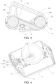
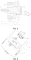
- FIGS. 1 to 15 A specific structure of a cordless lamp of an embodiment of the present disclosure is described below with reference to FIGS. 1 to 15 .
- an additional protective cover 82 effectively prevents inadvertent activation of the switch 7 caused by the button 81 being inadvertently pressed during product handling and transportation process. Therefore, the situation is avoided that the built-in power loss caused by the lighting of the cordless lamp during the handling process will affect the quality of the product shipped.
- the button 81 includes a flexible piece 811 and a rigid piece 812 embedded in an end of the flexible piece 811 opposite to the trigger surface of the switch 7. It can be understood that if the flexible piece 811 is in direct contact with the trigger surface, during long-term use, it is easy to cause material fatigue, aging and other phenomena at an end of the flexible piece 811 that is in contact with the trigger surface, thereby making the flexible piece 811 ineffective when pressed and unable to be used normally.
- the rigid piece 812 added in the present embodiment can effectively prevent the flexible piece 811 from being in direct contact with the trigger surface of the switch 7, thereby effectively improving a service life of the button 81 and improving reliability when the button 81 is pressed. At the same time, operation hand feeling of the button 81 is effectively improved, which effectively avoids occurrence of conditions such as pressing failure of the button 81.
- the button assembly 8 further includes a mounting plate 83 connected to an inner sidewall of the housing.
- the flexible piece 811 includes a body 8111 and a protruding ring 8112 arranged around the body 8111. An end of the body 8111 passes through the housing to be fitted with the protective cover 82, and another end passes through the mounting plate 83 to be fitted with the rigid piece 812.
- the protruding ring 8112 is clamped between the mounting plate 83 and the inner sidewall of the housing. Therefore, the mounting plate 83 is capable of firmly pressing the button 81 in the housing, thereby better ensuring stability of the button 81.
- one of the body 8111 and the sidewall of the housing is openly provided with an annular mounting groove, and the other one is provided with a mounting bump adapted to the mounting groove.
- the housing is openly provided with the fitting hole, the sealing performance of the whole cordless lamp is reduced to a certain extent.
- sealing at the fitting hole is better realized by mating of the mounting bump and the mounting groove and the pressing effect of the mounting plate 83 on the protruding ring 8112, thereby ensuring the sealing performance of the cordless lamp.
- the circuit board 32 include a main control module, a light source control module, a charge management module, a discharge management module and a light source control module.
- the charge management module and the discharge management module are each electrically connected to the main control module.
- the light source control module is electrically connected to the light-emitting element 33.
- the charge management module and the discharge management module are each electrically connected to the power supply 9.
- the housing is provided with a charge interface and a discharge interface.
- a charge structure is electrically connected to the charge management module.
- the discharge interface is electrically connected to the discharge management module.
- the circuit board 32 of the cordless lamp of the present disclosure includes the charge management module, and the discharge management module, that is to say, the cordless lamp of the present disclosure has a charge function and a discharge function.
- the cordless lamp of the present disclosure has a charge function and a discharge function.
- the cordless lamp is capable of charging other external devices, thereby expanding a use range of the cordless lamp.
- the charge management module and the discharge management module are integrated into a charge and discharge module, and the charge interface and the discharge interface are integrated into a charge and discharge interface 6. Therefore, a structure of the circuit board 32 is simplified, and hole/groove structures on the bottom housing 1 and the cover housing 2 are reduced, thereby indirectly improving the sealing performance of the cordless lamp of the embodiment of the present disclosure.
- the circuit board 32 is further provided with a charge and discharge indicator lamp electrically connected to the charge and discharge module. Therefore, the charge and discharge indicator lamp is capable of indicating a charging or discharging state of the cordless lamp, thereby giving a very intuitive display to the user.
- the charge and discharge interface 6 is a non-plug type magnetic interface. It can be understood that the non-plug type magnetic interface ensures that the charge and discharge interface has good sealing performance with the bottom housing 1 or the cover housing 2. At the same time, an interface area 61 has no groove structure, making it not affected by foreign objects.
- the charge and discharge interface 6 includes the interface area 61 formed on the bottom wall of the housing.
- the interface area 61 is provided with two charge and discharge contact points 62 protruding on the interface area 61.
- the interface area 61 is covered with a covering.
- the two charge and discharge contact points 62 are magnetic contact points. It can be understood that since the charge and discharge contact points 62 protrude out from the interface area 61, there is no groove structure at an electrical connection of the whole charge/discharge interface. Therefore, the electrical connection is not affected by foreign objects after completion, and an integral clamping groove type of charging and discharging can be used.
- the interface area 61 is coat with stainless iron sheets.
- the charge and discharge contact points 62 are magnetic contact points
- the magnetic contact charger connector can be used to charge a device through a magnetic force adsorption of the stainless iron sheets. Additionally or alternatively, the charge and discharge contact points 62 are the magnetic contact points, which is very convenient.
- a top portion of the charge and discharge contact point 62 is flush with the bottom wall of the housing, and the interface area 61 is located at an edge position of the housing. It can be understood that since an area of the interface area 61 is relatively small, the bottom wall of the housing is flush with a top portion of the charge and discharge contact point 62, so that a surface of the housing of the whole cordless lamp is relatively flat. At the same time, the interface area 61 is located at the edge position of the interface housing. When the device uses an integral clamping groove of charging mode, an elastic charging electrode of a charger will not contact the interface area 61 and scratch the housing.
- the housing is a plastic member, and a side surface of the charge and discharge contact point is sealed by the interface area 61 by injection molding. Therefore, the side surface of the charge and discharge contact point 62 and the interface area 61 are sealed by injection molding, thereby improving the sealing performance of the whole cordless lamp.
- the circuit board 32 is provided with a welding hole 322.
- An end of the charge and discharge contact point 62 is fitted in the welding hole 322 and is fixed to the circuit board 32 by soldering. In this way, connection stability between the charge and discharge contact point 62 and the circuit board 32 can be better ensured, which improves reliability, impact resistance and explosion-proof performance of the cordless lamp, thereby ensuring stable charging and discharging of the cordless lamp.
- the interface area 61 is provided with a limit slot 612 and two guide slots 611.
- the limit slot 612 and the two guide slots 611 are distributed in an isosceles triangle.
- a length of the limit slot 612 is perpendicular to a length of the guide slot 611. It can be understood that when the magnetic contact charger connector is close to the interface area 61, the charging or discharging connector and the charge and discharge contact point 62 will generate a relatively large magnetic absorption force.
- the guide slot 611 located at an outer side of the charge and discharge contact point 62 is mated with a guide boss on the charging or discharging connector, so that the charging or discharging connector and the charge and discharge contact point 62 are easily aligned and in good contact.
- the limit slot 612 in the interface area 61 is capable of well limiting a position of a charging or discharging connector. After the charging is completed, in removing the charging or discharging connector, the limit slot 612 serves as a fulcrum. Therefore, the charging or discharging connector can be easily removed.
- the limit slot 612 is an arc-shaped groove, whereby when the guide boss of the magnetic contact charging or discharging connector rotates in the arc-shaped groove, an arc-shaped structure of an inner surface of the groove makes the guide boss smoothly rotate and easily taken out.
- the bottom wall of the housing is provided with two first sliding grooves 15 located on two sides of the interface area 61, and a top wall of the housing is provided with two second sliding grooves 26 located on two sides of the interface area 61.
- first sliding groove 15 and the second sliding groove 26 are used to position and clamp the cordless lamp onto the charging or discharging connector, thereby ensuring the stability of the cordless lamp.
- the light-emitting element 33 includes a primary light source 331 and a secondary light source 332 disposed around the primary light source 331.
- the light source control module includes a primary light source control module electrically connected to the primary light source 331 and a secondary light source control module electrically connected to the secondary light source 332. Therefore, independent control of the primary light source 331 and the secondary light source 332 enables the cordless lamp of the present embodiment to provide different light intensities and light-emitting effects, thereby expanding the use range of the cordless lamp.
- the four secondary light sources 322 are capable of providing different combination prompts during a charge/discharge process of the cordless lamp, which can be applied in emergency or other scenes, thereby greatly improving the user experience.
- the housing is provided with buttons connected to the secondary light source control module.
- the user can press different buttons according to actual needs so that the secondary light source 322 provides different combined illuminating prompts. Operation of such button switching is very convenient, so that the user is convenient to switch states of the secondary light source 322, thereby greatly improving the user experience.
- the housing includes the bottom housing 1 and the cover housing 2.
- An upper end of the bottom housing 1 is openly arranged, and an open end of the bottom housing 1 is provided with a clamping groove 11 and a snap ring 12 arranged on an inner wall of the bottom housing 1.
- a lower end of the cover housing 2 is openly arranged, and the cover housing 2 is buckled on the bottom housing 1.
- the cover housing 2 is provided with a first locking protrusion 21 and a second locking protrusion 22.
- the first locking protrusion 21 is clamped on and abutted against the snap ring 12 so that the open end of the bottom housing 1 abuts against an open end of the cover housing 2 to form a first waterproof structure.
- the second locking protrusion 22 is fitted in the clamping groove 11.
- An adhesive is filled between the second locking protrusion 22 and the clamping groove 11 to form a second waterproof structure.
- the first locking protrusion 21 is clamped on and abutted against the snap ring 12 so that the open end of the bottom housing 1 abuts against the open end of the cover housing 2 to form the first waterproof structure, and the adhesive is filled between the second locking protrusion 22 and the clamping groove 11 to form the second waterproof structure.
- two waterproof structures are formed between the bottom housing 1 and the cover housing 2 of the cordless lamp in the present embodiment, thereby better improving waterproof performance of the cordless lamp and the reliability of use of the high-bay light.
- the bottom housing 1 and the cover housing 2 are made of polytetrafluoroethylene, and the adhesive is polyurethane adhesive or other low-temperature quick-drying adhesive. Materials of the bottom housing 1 and the cover housing 2 and a type of the adhesive can be selected according to actual needs and are not to be limited to the above description.
- the cordless lamp of the present embodiment when assembling the cordless lamp of the present embodiment, firstly, it is necessary to place an appropriate amount of adhesive in the clamping groove 11, and the amount of the adhesive ranges from 1/5 to 1/3 of a depth of the clamping groove 11. Secondly, it is necessary to ensure that the first locking protrusion 21 is aligned with the snap ring 12, the second locking protrusion 22 of the cover housing 2 is inserted into the clamping groove 11, and the first locking protrusion 21 is clamped on and abutted against the snap ring 12. Finally, the adhesive is cured to realize adhesion between the bottom housing 1 and the cover housing 2. In order to ensure adhesion strength between the bottom housing 1 and the cover housing 2, curing may be performed twice or more times. Further, the curing may be normal temperature curing or ultraviolet curing. A specific curing type may be selected according to a type of the adhesive, and is not limited to the aforementioned normal temperature curing and ultraviolet curing.
- the first locking protrusion 21 is provided with a first inclined surface 211 inclined in a downward direction toward an inner wall close to the cover housing 2.
- the snap ring 12 is provided with a second inclined surface 121 inclined in an upward direction toward an inner wall away from the bottom housing 1. It can be understood that during an actual mounting process, in a process of inserting the second locking protrusion 22 of the cover housing 2 into the clamping groove 11, the first locking protrusion 21 needs to be moved from a position where the first locking protrusion 21 is clamped on and abutted against an upper end surface of the snap ring 12 to a position where the first locking protrusion 21 is clamped on and abutted against a lower cross section of the snap ring 12.
- Arrangement of the first inclined surface 211 and the second inclined surface 121 is capable of conveniently realizing movement of the first locking protrusion 21 relative to the snap ring 12, so that the first locking protrusion 21 can be more smoothly clamped on and abutted against the snap ring 12.
- a plurality of first locking protrusions 21 are spaced apart along a circumferential direction of the cover housing 2 and a plurality of snap rings 12 are spaced apart along an axial direction of the bottom housing 1. Therefore, engagement of the plurality of first locking protrusions 21 and the plurality of snap rings 12 can ensure connection stability and the connection sealing performance of the cover housing 2 and the bottom housing 1, thereby ensuring reliability of the whole cordless lamp.
- the snap groove 11 is an annular groove provided around an open end of the bottom housing 1, and the second locking protrusion 22 is formed as an annular protrusion around the cover housing 2. Therefore, a contact area between the second locking protrusion 22 and the clamping groove 11 is increased, thereby ensuring the connection stability and the connection sealing performance of the bottom housing 1 and the cover housing 2.
- the annular groove is located in a middle portion of a top wall of the bottom housing 1, and the second locking protrusion 22 is formed in a middle portion of a bottom wall of the cover housing 2. In this way, the connection stability and the connection sealing performance of the bottom housing 1 and the cover housing 2 are further ensured.
- a bottom wall of the clamping groove 11 is provided with a groove structure
- a lower end of the second locking protrusion 22 is provided with a protruding structure mated with the groove structure. It can be understood that engagement of the groove structure and the protruding structure is capable of limiting shaking of the second locking protrusion 22 in the clamping groove 11, which improves connection stability of the second locking protrusion 22 and the clamping groove 11, thereby further ensuring the connection stability and the connection sealing performance of the bottom housing 1 and the cover housing 2.
- a sidewall of the second locking protrusion 22 is provided with an inclined protrusion 221 inclined from top to bottom toward a direction away from the second locking protrusion 22.
- liquid adhesive is capable of completely wrapping each part of a main body 24 of the second locking protrusion 22 and the inclined protrusion 221.
- the inclined protrusion 221 is capable of increasing a contact area between the second locking protrusion 22 and the adhesive, which effectively improves an adhesive force between the second locking protrusion 22 and the adhesive, thereby ensuring the connection stability and connection sealing performance of the cover housing 2 and the bottom housing 1.
- the incline protrusion 221 is inclined from top to bottom toward a direction away from the second locking protrusion 22, so that the adhesive between the incline protrusion 221 and the main body 24 of the second locking protrusion 22 is capable of effectively preventing the second locking protrusion 22 from being detached from an adhesive portion, thereby ensuring close adhesion between the bottom housing 1 and the cover housing 2.
- the lower end of the second locking protrusion 22 is provided with a wedge-shaped protrusion 222 whose cross-sectional area gradually increases from top to bottom.
- the additional wedge-shaped protrusion 222 is capable of increasing an adhesive contact area between the second locking protrusion 22 and the adhesive.
- a cross-sectional area of the wedge-shaped protrusion 222 gradually increases in a direction away from the second locking protrusion 22.
- the adhesive between the wedge-shaped protrusion 222 and the second locking protrusion 22 is capable of effectively preventing the second locking protrusion 22 from being detached from the adhesive portion, thereby ensuring close adhesion between the bottom housing 1 and the cover housing 2.
- two oppositely disposed sidewalls of the second locking protrusion 22 are each provided with a limiting step 223 extending along a length of the second locking protrusion 22, and a height of the limiting step 223 is lower than that of the second locking protrusion 22. It can be understood that when the second locking protrusion 22 is inserted into the clamping groove 11, the limiting steps 223 on two sides are abutted against two oppositely disposed sidewalls of the clamping groove 11, respectively, which further increases an adhesive sealing contact surface between the bottom housing 1 and the cover housing 2, thereby increasing sealing adhesive strength.
- the second locking protrusion 22 is uniformly provided with first sawtooth grooves 224.
- the clamping groove 11 is provided with an inner groove edge 111 and an outer groove edge 112.
- the inner groove edge 111 is uniformly provided with second sawtooth grooves 1111 interlaced with the first sawtooth grooves 224.
- the first sawtooth grooves 224 and the second sawtooth grooves 1111 that are interlaced with each other are capable of eliminating bubbles in a gap between the second locking protrusion 22 and the clamping groove 11, thereby avoiding generation of bubbles during adhesion. Even if there are bubbles, large bubbles can be decomposed into smaller bubbles through the serrated structure, which avoids presence of large bubbles in adhesive seams, thereby ensuring the connection sealing performance of the bottom housing 1 and the cover housing 2, so that a structure between the bottom housing 1 and the cover housing 2 is more firm and reliable.
- a tooth spacing between each of the adjacent first sawtooth grooves 224 and the second sawtooth grooves 1111 is L, and a staggered distance between each of the adjacent first sawtooth groove 224 and the second sawtooth groove 1111 is L/2 when the bottom housing 1 and the cover housing 2 are mated.
- first sawtooth grooves 224 and the second sawtooth grooves 1111 have a same serrated groove spacing, and the staggered distance is U2, so that staggered arrangement of the first sawtooth groove 224 and the second sawtooth groove 1111 is more regular, which can better decompose the large bubbles in the adhesive into smaller bubbles, and further eliminate the smaller bubbles, thereby ensuring the connection sealing performance of the bottom housing 1 and the cover housing 2, so that the structure between the bottom housing 1 and the cover housing 2 is more firm and reliable.
- the second locking protrusion 22 is further uniformly provided with a third serrated groove with a tooth spacing L.
- Serrated grooves of the third serrated grooves and the first sawtooth grooves 224 are arranged at intervals. Positions of the third serrated grooves and the second sawtooth grooves 1111 are disposed directly opposite in one-to-one correspondence when the bottom housing 1 and the cover housing 2 are mated. It can be understood that the third serrated grooves are each arranged at intervals between two adjacent first sawtooth grooves 224, and a spacing distance between each of the third serrated groove and the serrated groove of the first sawtooth groove 224 is U2.
- a total number of serrated grooves provided on the cover housing 2 is twice a number of serrated grooves on the bottom housing 1, and a number of serrated grooves on the bottom housing 1 is less than a number of serrated grooves on the cover housing 2, thereby preventing glue leakage caused by too many serrated grooves on the bottom housing 1 and affecting a glue pouring effect.
- bottoms of the first sawtooth groove 224, the second sawtooth groove 1111, and the third serrated groove of the present disclosure are arc-shaped. Therefore, formation of sharp angle at the bottom of the serrated groove can be avoided, which is beneficial to eliminating bubbles.
- a height of the outer groove edge 112 is higher than a height of the inner groove edge 111. In this way, the poured adhesive glue can be prevented from overflowing, thereby solving the problem that it is difficult to clean up residual adhesive caused by overflow of the adhesive.
- a groove depth of the second sawtooth groove 1111 is half a groove depth of the clamping groove 11. It can be understood that for the sake of smooth glue pouring, the groove depth of the second sawtooth groove 1111 cannot be too deep, otherwise, the adhesive is easy to overflow, nor can the groove depth of the second sawtooth groove 1111 be too shallow, otherwise, in a case where there are bubbles at a relative bottom of the clamping groove 11, the second locking protrusion 22 of the cover housing 2 cannot play a role of using a sawtooth to cut bubbles for bubble dissipation.
- the depth of the second sawtooth groove 1111 is designed to be half of the groove depth of the clamping groove 11, which can better correspond to the first sawtooth groove 224 on the second locking protrusion 22, thereby realizing defoaming.
- the present disclosure designs that a groove width of each serrated groove of the first sawtooth groove 224, the second sawtooth groove 1111 and the third serrated groove ranges from 1mm to 3mm, and a value range of L/2 ranges from 1mm to 5mm.
- a thickness of the second locking protrusion 22 ranges from 1mm to 5mm.
- a width of the clamping groove 11 ranges from 1.1 mm to 5.1 mm. The width of the clamping groove 11 is greater than the thickness of the second locking protrusion 22, and a difference value between the two ranges from 0.1 mm to 0.5 mm. It can be understood that in the present embodiment, the adhesive is filled between the second locking protrusion 22 and the clamping groove 11 to form the second waterproof structure, so that the width of the clamping groove 11 is greater than the thickness of the second locking protrusion 22.
- the thickness of the second locking protrusion 22 is controlled between 1mm and 1.5 mm, and the width of the clamping groove 11 is controlled between 1.1 mm and 5.1 mm.
- the difference value between the width of the clamping groove 11 and the thickness of the second locking protrusion 22 is controlled between 0.1 mm and 0.5 mm, so that the connection stability and sealing performance of the bottom housing 1 and the cover housing 2 can be better ensured, and the strength of the second locking protrusion 22 can be further ensured.
- the volume and weight of the bottom housing 1 and the cover housing 2 are limited, which is beneficial to the lightweight and miniaturization design of the cordless lamp.
- the width of the clamping groove 11 ranges from 3.2 mm to 4.2 mm, and the thickness of the second locking protrusion 22 ranges from 3mm to 4mm.
- the difference value between the width of the clamping groove 11 and the thickness of the second locking protrusion 22 ranges from 0.2 mm to 0.4 mm.
- the width of the clamping groove 11, the thickness of the second locking protrusion 22, and the difference value between the width of the clamping groove 11 and the thickness of the second locking protrusion 22 can be selected according to actual needs, and are not limited to the above-mentioned limitations.
- the height of the second locking protrusion 22 ranges from 5mm to 10mm
- the depth of the clamping groove 11 ranges from 5.1 mm to 10.1 mm
- the difference value between the depth of the clamping groove 11 and the height of the second locking protrusion 22 ranges from 0.1 mm to 0.5 mm.
- the depth of the clamping groove 11 ranges from 6.2mm to 8.2 mm
- the height of the second locking protrusion 22 ranges from 6 mm to 8 mm.
- the difference value between the depth of the clamping groove 11 and the height of the second locking protrusion 22 ranges from 0.2 mm to 0.4 mm.
- the depth of the clamping groove 11, the height of the second locking protrusion 22, and the difference value between the depth of the clamping groove 11 and the height of the second locking protrusion 22 can be selected according to actual needs, and are not limited to the above-mentioned limitations.
- a sidewall and a bottom wall of the bottom housing 1 are provided with a plurality of reinforcing ribs 13. Therefore, the bottom housing 1 is capable of bearing a relatively large impact force from the outside, and normal use of the whole cordless lamp in a field or water working environment can be ensured.
- the cordless lamp further includes a hook module 4 and a friction rotational shaft 5.
- the hook module 4 is disposed on the bottom wall of the bottom housing 1 and provided with a mounting tug 411 and a nail hanging hole 401. One end of the friction rotational shaft 5 is inserted through the mounting tug 411, and the other end is connected to the bottom housing 1.
- the hook module 4 is capable of rotating relative to the friction rotational shaft 5, and the friction rotational shaft 5 is configured to maintain the hook module 4 at a position arranged at an included angle with the bottom housing 1.
- the existing hook module 4 is usually directly fixed and mounted on the bottom housing 1 of the cordless lamp, so that a relative position between the cordless lamp and the hook module 4 is fixed.
- the cordless lamps are sometimes required to illuminate at different angles.
- an illuminating angle of the cordless lamp cannot be changed, which limits application scenarios of the cordless lamp.
- the hook module 4 is connected to the bottom housing 1 through the friction rotational shaft 5.
- the hook module 4 is capable of rotating relative to the friction rotational shaft 5, and the friction rotational shaft 5 is configured to maintain the hook module 4 at a position arranged at an included angle with the bottom housing 1. That is to say, in an actual use process, the hook module 4 is capable of rotating relative to the bottom housing 1, so that the illuminating angle of the cordless lamp can be arbitrarily changed, thereby expanding the application range of the cordless lamp.
- the hook module 4 is capable of rotating relative to the bottom housing 1, in the actual practical process, the hook module 4 can also be used as a bracket for the cordless lamp, which is quite convenient.
- a rotating angle of the hook module 4 can be adjusted to 50°.
- the hook module 4 includes a first plate member 41 and a second plate member 42.
- the first plate member 41 is provided with two mounting tugs 411 oppositely disposed to each other, and an clearance notch 412.
- One end of the second plate member 42 is connected to the first plate member 41, and a projection of the second plate member 42 in a vertical direction coincides with a projection of the first plate member 41 in a vertical direction.
- the second plate member 42 is provided with a nail hanging hole 401, and the nail hanging hole 401 is provided corresponding to the clearance notch 412.
- first plate member 41 and the second plate member 42 projections of the first plate member 41 and the second plate member 42 in the vertical direction coincide, the first plate member 41 and the second plate member 42 are oppositely arranged to each other, so that strength of the hook module 4 can be improved to prevent the hook module 4 from being broken, and space between the first plate member 41 and the second plate member 42 can hide a top cap of the hanging nail, thereby avoiding potential safety hazard caused by protrusion of the top cap.
- the second plate member 42 includes a first inclined plate 421 and a second inclined plate 422.
- One end of the first inclined plate 421 is connected to the first plate member 41 by a fillet, and the first inclined plate 421 is inclined along a length of the first plate member 41 toward a direction close to the first plate member 41.
- One end of the second inclined plate 422 is connected to the first inclined plate 421.
- the second inclined plate 422 is inclined in a direction away from the first inclined plate 421 toward a direction away from the first plate member 41, and a connecting section of the second inclined plate 422 and the first inclined plate 421 abuts against the first plate member 41.
- the second plate member 42 is formed as a duck tongue mechanism forming of the first inclined plate 421 and the second inclined plate 422.
- Such duck tongue structure enables the user to easily hang a hanging portion into an upper position between the first plate member 41 and the second plate member 42 of the hook module 4 through the duck tongue structure when using the hook module 4.
- the hanging portion is capable of tightly pressing against a bending portion (i.e., a connecting member of the first plate member 41 and the second plate member 42) of the duck tongue structure without moving, thereby ensuring use reliability of the hook module 4.
- the first plate member 41 and the second plate member 42 are formed by bending an integral plate. At an upper portion, the first plate member 41 and the second plate member 42 are bent and formed with a distance of about 2mm. A size of the main body 24 of the second plate member 42 is 33 mm ⁇ 20 mm. A thickness of the second plate member 42 is the same as that of the first plate member 41 and is 1mm.
- the duck tongue structure is formed at a lower portion of the second plate member 42 about 10mm from a bottom edge. The lower bottom edge of the second plate member 42 is about 2mm away from the first plate member 41.
- the nail hanging hole 401 includes a first elongated hole 4011, a second elongated hole 4012 and a third elongated hole 4013.
- a width of the first elongated hole 4011 is greater than a width of the second elongated hole 4012, and the width of the second elongated hole 4012 is greater than a width of the third elongated hole 4013.
- the second elongated hole 4012 is connected to an end of the first elongated hole 4011 facing toward a joint of the first plate member 41 and the second plate member 42
- the third elongated hole 4013 is connected to an end of the second elongated hole 4012 facing toward a joint of the first plate member 41 and the second plate member 42.
- the first elongated hole 4011 is relatively wide, which facilitates extending the nail cap into the nail hanging hole 401, while the second elongated hole 4012 and the third elongated hole 4013 are relatively narrow to restrict the nail cap from sliding out of the nail hanging hole 401 on a premise that a nail body is capable of passing through, which ensures that the hanging nail can be stably maintained in the nail hanging hole 401, thereby ensuring the nail hanging stability of the cordless lamp.
- a first elongated hole 4011 of 12.5 ⁇ 9.5 mm is laterally centered about 10mm away from the bottom edge of the second plate member 42, and a second elongated hole 4012 with a width of 5.3 mm and a third elongated hole 4013 with a width of 4.2 mm are sequentially connected to the first elongated hole 4011, where the second elongated hole 4012 is about 11mm and the third elongated hole 4013 is about 6mm away from a top portion of the second plate member 42.
- the first elongated hole 4011 and the second elongated hole 4012 are transitioned by an edge fillet.
- the second elongated hole 4012 and the third elongated hole 4013 are transitioned by an edge fillet.
- a top portion of the third elongated hole 4013 has a semi-circular arc structure with a diameter of 4.2 mm.
- the structure of the nail hanging hole 401 of the present embodiment may be applied to hanging nails with diameters of 5.0 mm and 4.0 mm, respectively, or different nail hanging holes 401 may be set according to different nail-hanging sizes.
- the friction rotational shaft 5 includes an smooth shaft 51, a friction piece 52, and a pressing cap 53.
- One end of the smooth shaft 51 is provided with the connecting hole.
- the smooth shaft 51 is connected to the bottom housing 1 through the connecting member inserted through the connecting hole.
- a plurality of the friction pieces 52 are provided and inserted through the smooth shaft 51.
- the pressing cap 53 is connected to the other end of the smooth shaft 51 and used for pressing the friction piece 52.
- the smooth shaft 51 ensures that the friction rotational shaft 5 can be stably connected to the bottom housing 1 and that the hook module 4 is capable of rotating stably relative to the bottom housing 1, while the friction piece 52 ensures that the hook module 4 is maintained at a position arranged at an included angle with the bottom housing 1 when rotating at a certain angle relative to the bottom housing 1,
- the hook module 4 and the friction rotational shaft 5 are made of stainless steel, so that the hook module 4 and the friction rotational shaft 5 possess strong corrosion resistance and can be used under very complex and harsh conditions.
- the hook module 4 further includes a fourth plate member 43 with mounting tugs 431 provided on two opposite sidewalls of the fourth plate member 43 and with the nail hanging hole 401 provided thereon.
- the hook module 4 is connected to the bottom housing 1 through the connecting member inserted through the mounting tug 431. It can be understood that the whole cordless lamp needs to be fixed at a certain angle in some specific use occasions. At this moment, if the hook module 4 is capable of rotating relative to the bottom housing 1, it will affect the normal use of the cordless lamp instead.
- the hook module 4 is fixed on the bottom housing 1 through the connecting member inserted through the mounting tug 431, the connection stability between the hook module 4 and the bottom housing 1 is ensured, thereby preventing the hook module 4 from rotating relative to the bottom housing and improving using satisfaction of the user.
- the nail hanging hole 401 includes the first elongated hole 4011, the second elongated hole 4012 and a closed hole 4014.
- the width of the first elongated hole 4011 is greater than that of the second elongated hole 4012.
- the second elongated hole 4012 is connected to one end of the first elongated hole 4011 facing toward the mounting tug 431.
- the first elongated hole 4011 is relatively wide, which facilitates extending the nail cap into the nail hanging hole 401, while the second elongated hole 4012 is relatively narrow to restrict the nail cap from sliding out of the nail hanging hole 401 on a premise that the nail body is capable of passing through, which ensures that the hanging nail can be stably maintained in the nail hanging hole 401, thereby ensuring the nail hanging stability of the cordless lamp.
- arrangement of the closed hole 4014 enables the cordless lamp to be applied to special use scenarios.
- the hanging nail is a stud instead of a screw. Stability of the whole cordless lamp can be better ensured by mating the closed hole 4014 with the stud.;
- the fourth plate member 43 and the mounting tug 431 are integrally formed. Therefore, structural stability of the hook module 4 is improved, avoiding a phenomenon that the mounting tug 431 is broken.
- the fourth plate member 43 and the mounting tug 431 are plastic members. Therefore, production cost and weight of the hook module 4 can be reduced, and wear resistance and corrosion resistance of the hook module 4 are improved.
- the fourth plate member 43 and the mounting tug 431 may be selected from any material according to actual needs and are not limited to the plastic of the present embodiment.
- a front side and a rear side of the bottom housing 1 are provided with a first curved portion 14, respectively.
- a front side and a rear side of the cover housing 2 are provided with a second curved portion 23, respectively.
- the second curved portion 23 is arranged corresponding to the first curved portion 14.
- the first curved portion 14 and the second curved portion 23 define an curved battery compartment 101.
- a cross section of the curved battery compartment 101 is a partial circle ranges from 1/2 to 3/4 of one circle.
- a battery compartment in a housing of a cordless lamp of the existing art either adopts a packaged type with poor heat dissipation effect or adopts a fully open type that cannot well secures a power supply 9.
- the curved battery compartment 101 is formed of the first curved portion 14 of the bottom housing 1 and the second curved portion 23 of the cover housing 2. That is, the curved battery compartment 101 of the present embodiment is a semi-open battery compartment, which can not only improve stability of the power supply 9 but ensure a better heat dissipation effect.
- the cordless lamp since the cordless lamp includes two curved battery compartments 101, one power supply 9 can be mounted in each battery compartment, thereby improving endurance of the cordless lamp.
- the power supply 9 is a high-efficiency charging power supply 9. Therefore, the endurance of the cordless lamp can be further improved.
- a cross section of the curved battery compartment 101 ranges from 3/5 to 2/3 of one circle.
- a cross section of the first curved portion 14 accounts for 1/8 of one circle, and a cross section of the second curved portion 23 accounts for 1/4 of one circle.
- the cross section of the first curved portion 14 accounts for 1/2 of one circle, and the cross section of the second curved portion 14 accounts for 3/8 of one circle.
- cross-sectional shapes of the curved battery compartment 101, the first curved portion 14 and the second curved portion 23 can be selected according to actual needs, and are not limited to the above description.
- the two curved battery compartments 101 are located on two sides of the circuit board 32, thereby reducing a lateral width of the cordless lamp.
- the cover housing 2 includes the main body 24 and a lamp hood 25 protruding on the main body 24.
- the lamp hood 25 has a light outbound surface 251, and the light outbound surface 251 is arranged at an included angle with the bottom wall of the cover housing 2.
- a lamp hood 25 or lamp glass of the existing art is disposed coplanar with the main body 24.
- other components e.g., the power supply 9, the circuit board 32, etc.
- heavier components such as the power supply 9 and components such as the reflective cup 31 of the cordless lamp are disposed at a same relative position. These heavier components cause a relatively large position offset of the center of gravity of the whole cordless lamp relative to the hook module 4 of the cordless lamp, and the user feels that the cordless lamp is relatively heavy and uncomfortable when hanging the cordless lamp on a safety helmet by the hook.
- the lamp hood 25 is arranged protruding from the main body 24, so that during a mounting process, the lamp hood 25 is used for mounting the reflective cup 31 of the cordless lamp, and other heavier components such as the power supply 9, the circuit board 32 are mounted in the main body 24, so that the position offset of the center of gravity of the whole cordless lamp relative to the hook module 4 of the cordless lamp is reduced, and the user feels that an overall weight is relatively light when using the cordless lamp.
- the main body 24 and the lamp hood 25 are of an integrated structure, so that the structure is simple and the lamp hood 25 and the main body 24 do not need to be connected and mounted again, simplifying a structure of the cover housing 2, thereby improving an aesthetic degree of the cordless lamp.
- the main body 24 and the lamp hood 25 can be integrally molded with transparent plastic, so that the main body 24 and the lamp hood 25 can be molded by an injection molding method. A processing technology is simple and corresponding economic benefits are quite good.
- an included angle between the light outbound surface 251 and the bottom wall of the cover housing 2 is 22°. Because in most cases, the cordless lamp is used with an illuminating angle of 22°, the included angle between the light outbound surface 251 and the bottom wall of the cover housing 2 is set to 22°, so that when mounting the cordless lamp, it is not necessary to rotate the cordless lamp, thereby facilitating mounting the cordless lamp.
- the light outbound surface 251 is recessed in the lamp hood 25, so as to reduce possibility of scratches on the light outbound surface 251, thereby ensuring light-emitting stability of the cordless lamp.
- the light-emitting module 3 includes the light-emitting cover 31 and the circuit board 32.
- the light-emitting cover 31 is arranged in the lamp hood 25, and a top wall of the light-emitting cover 31 abuts against the light outbound surface 251.
- a bottom wall of the light-emitting cover 31 is provided with a mating hole.
- the circuit board 32 is provided with a light-emitting element 33 fitted in the mating hole. Therefore, the reflective cup 31 is capable of increasing a light-emitting range of the light-emitting element 33, thereby ensuring an illuminating range of the cordless lamp of the present embodiment.
- the bottom housing 1 is provided with a supporting protrusion 16, and the circuit board 32 is clamped between the supporting protrusion 16 and the reflective cup 31.
- the circuit board 32 is mostly fixed in forms such as columns or screws, which usually wastes a large internal space of the circuit board 32, thereby increasing an external volume of the cordless lamp.
- the circuit board 32 is clamped between a bottom portion of the reflective cup 31 and the support, thereby greatly saving the internal space and reducing a size of a housing of the cordless lamp.
- an included angle between the circuit board 32 and a horizontal plane perpendicular to the bottom wall of the bottom housing 1 ranging from 90° to 160°.
- the circuit board 32 of the existing cordless lamp mostly adopts a fixing method that is set at 90° perpendicular to the horizontal plane. In this fixing method, users often need to lower their heads in order to clearly see situations below, thereby reducing comfort of a user experience process.
- an included angle between the circuit board 32 and the horizontal plane perpendicular to the bottom wall of the bottom housing 1 ranges from 90° to 160°, so that the user can clearly see the situation below without lowering his head, thereby greatly improving the comfort of the user experience process.
- the included angle between the circuit board 32 and the horizontal plane perpendicular to the bottom wall of the bottom housing 1 ranges from 100° to 240°, which is more in line with ergonomic requirements of the user experience process.
- the circuit board 32 is provided with a fitting hole 321, and the bottom wall of the reflective cup 31 is provided with a mounting protrusion 311 mated with the fitting hole 321.
- the reflective cup is fixedly connected to the circuit board 31 through an integrally formed mounting protrusion 311, so that stability of the connection between the reflective cup 31 and the circuit board 32 is improved, thereby ensuring a center coincidence spotlighting effect of a primary light source 331, and ensuring the illuminating effect of the cordless lamp.
- the mounting protrusion 311 is formed as a trapezoidal snap, and a structure of the trapezoidal snap itself forms a certain radian, making it more convenient for using a mold, at the same time, the trapezoidal snap is connected to a cross section of the circuit board 32 to form a circular arc surface connection without damaging a structure of the circuit board 32, so that the reflective cup 31 is effectively fixed on the circuit board without causing contact wear to the circuit board 32.
- a bottom portion of the reflective cup 31 located at an outer side of the trapezoidal snap is provided with a hollow-out hole.
- the hollowed-out hole can provide deformation space for the trapezoidal snap, which is beneficial to elastic deformation and reset when the trapezoidal snap is clamped with the circuit board 32.
- the reflective cup 31 and the trapezoidal snap are integrally injection molded with PC material. Aluminum is electroplated on a surface of the reflective cup 31 by vacuum electroplating, thereby effectively improving the light-emitting efficiency of the light-emitting element 33.
- the reinforcing structure 3111 is formed as an L-shaped structure.
- the reinforcing structure 3111 may select other structures, such as triangular structures, according to actual needs.
- the reinforcing structure 3111 is not limited to the L-shaped structure of the present embodiment.
- the light-emitting module 3 further includes a reflecting member 34 disposed in the reflective cup 31.
- One end of the reflecting member 34 is disposed corresponding to the light-emitting element 33, and a center line of the reflecting member 34 coincides with an axis of the reflective cup 31.
- the light emitted from the light-emitting element 33 is emitted from an edge of the reflective cup 31.
- the wide illuminating angle of the light-emitting element 33 is 90°.As illustrated in FIGS. 22 , 24 , and 26 , when the reflecting member 34 is provided in the reflective cup 31, the light emitted from the light-emitting element 33 is reflected by the reflecting member 34 and then emitted from the edge of the reflective cup 31, making the wide illuminating angle of the light-emitting element 33 become 158°.
- reflected light on a surface of the reflecting member 34 makes up for a range in which a reflection cover 1 cannot form a wide angle, that is, a range ranges from 90° to 158°.
- a range ranges from 90° to 158° a range ranges from 90° to 158°.
- the reflecting member 34 is provided in the reflective cup 31, after reflected by the reflective cup 31 for a first time, the light emitted from the light-emitting element 33 is reflected by the reflecting member 34 for a second time, and then emitted just from the edge of the reflective cup 31, so that the wide angle of the light-emitting element 33 becomes 169°.
- the light emitted from the light-emitting element 33 is reflected for two times by the reflective cup 31 and the reflecting member 34.
- the two times reflection light makes up for a range in which the reflection cover 1 cannot form a wide angle, that is, a range ranges from 158° to 169°. Therefore, the wide angle of the light-emitting element 33 is further increased.
- the wide angle of the light-emitting element 33 is increased, while the curve of the inner surface of the reflective cup 31 is not changed, so that the focusing brightness of the whole cordless lamp is not affected.
- the reflecting member 34 can be selected according to actual needs. As illustrated in FIG. 22 , the reflecting member 34 may be a cone adhesive to the lamp hood 25.
- the reflecting member 34 may be a frustum of a cone adhesive to the lamp hood 25.
- the reflecting member 34 has a structure of a frustum of a cone. Compared with the conical structure, the light-emitting element with the shape of a frustum of a cone enables the light emitted from the light-emitting element 33 to be directly emitted out without being reflected by a top portion of the cone and the reflective cup 31, thereby reducing a reflection loss and improving illuminating brightness of the cordless lamp.
- the reflecting member 34 may be in the shape of a frustum of a cone with a hollow structure 341 adhesive to the lamp hood 25.
- the hollow structure 341 forms a concave lens structure on a bottom surface of the reflecting member 34 and an inner surface of the lamp hood 25, so that a position where the light-emitting element forms a critical reflection point with a wide angle of 158° is near a small end of the reflecting member 34, which further reduces a height of the reflecting member 34, thereby further reducing loss of light emitted by the light source 2 due to reflection of the small end of the reflecting member 34.
- the above description is only an exemplary illustration of the reflecting member 34 and is not a complete limitation of the reflecting member 34. That is, in other embodiments of the present disclosure, the reflecting member 34 can be selected according to actual needs, and a maximum wide angle of the light-emitting element 34 is not limited to 158°.
- a frosted structure is located at a position of the reflecting member 34 corresponding to an outer surface of the lamp hood 25. Since a frosted surface can scatter light, a shadow formed by the reflecting member 34 on the light outbound surface 251 is reduced, thereby further enhancing the focusing brightness of the cordless lamp.
- the reflecting member 34 is made of transparent material, and most of the light emitted from the light-emitting element 33 can pass through the reflecting member 34, so that the focusing brightness of the cordless lamp is improved.
- the information storage bar code can be a two-dimensional code, a non-contact Radio Frequency Identification (RFID) tag or a Near Field Communication (NFC) tag, etc.
- RFID Radio Frequency Identification
- NFC Near Field Communication
- the information storage bar code can record identity information of the cordless lamp, such as a manufacturer, product parameters (e.g., a model of the lamp source) or a serial number of the cordless lamp.
- the NFC chip may contain a unique serial number. That is, each NFC tag corresponds to one unique random serial number (anticounterfeiting code).
- One serial number has N bits.
- data written in the NFC chip may be burned, and the user may only read the data.
- Content of the tag may also be encrypted.
- Ciphertext is written into the tag, and obtained ciphertext and serial number are sent to a decryption server to get decrypted, and then the decryption server feeds back a result.
Landscapes
- Engineering & Computer Science (AREA)
- General Engineering & Computer Science (AREA)
- Arrangement Of Elements, Cooling, Sealing, Or The Like Of Lighting Devices (AREA)
- Non-Portable Lighting Devices Or Systems Thereof (AREA)
Claims (9)
- Kabellose Lampe, umfassend:ein Gehäuse, das einen Montagehohlraum definiert, wobei eine Seitenwand des Montagehohlraums mit einem Passloch versehen ist;ein lichtemittierendes Modul (3), das im Gehäuse angeordnet ist und eine Leiterplatte (32) und ein auf der Leiterplatte (32) angeordnetes lichtemittierendes Element (33) umfasst;einen Schalter (7), der im Gehäuse angeordnet und elektrisch mit der Leiterplatte (32) verbunden ist, wobei der Schalter (7) zum Steuern eines Ein- und Ausschaltens des lichtemittierenden Elements (33) konfiguriert und mit einer Auslösefläche versehen ist;eine Knopfanordnung (8), die einen Knopf (81) und eine Schutzabdeckung (82) umfasst, wobei der Knopf (81) durch das Passloch eingeführt ist, ein Ende des Knopfes (81) funktionsfähig ist, um an der Auslösefläche anzuliegen und die Schutzabdeckung (82) auf das andere Ende des Knopfes (81) aufgesteckt ist, und wobei die Schutzabdeckung (82) an der Seitenwand des Gehäuses anliegt; undeine Stromversorgung (9), die im Gehäuse angeordnet und elektrisch mit der Leiterplatte (32) verbunden ist,wobei das lichtemittierende Modul (3) weiter eine reflektierende Schale (31) umfasst und wobei das Gehäuse ein Untergehäuse (1) und ein mit dem Untergehäuse (1) verriegeltes Deckelgehäuse (2) umfasst, wobei das Untergehäuse (1) mit einem Stützvorsprung (16) versehen ist und wobei die Leiterplatte (32) zwischen dem Stützvorsprung (16) und der reflektierenden Schale (31) eingeklemmt ist,wobei die Leiterplatte (32) ein Hauptsteuerungsmodul, ein Lichtquellensteuerungsmodul, ein Ladeverwaltungsmodul und ein Entladeverwaltungsmodul umfasst, wobei das Lichtquellensteuerungsmodul, das Ladeverwaltungsmodul und das Entladeverwaltungsmodul jeweils elektrisch mit dem Hauptsteuerungsmodul verbunden sind, wobei das Lichtquellensteuerungsmodul elektrisch mit dem lichtemittierenden Element (33) verbunden ist und wobei das Ladeverwaltungsmodul und das Entladeverwaltungsmodul jeweils elektrisch mit der Stromversorgung (9) verbunden sind, wobei das Gehäuse mit einer Ladeschnittstelle und einer Entladeschnittstelle versehen ist, wobei die Ladeschnittstelle elektrisch mit dem Ladeverwaltungsmodul verbunden ist und die Entladeschnittstelle elektrisch mit dem Entladeverwaltungsmodul verbunden ist,wobei das Ladeverwaltungsmodul und das Entladeverwaltungsmodul in einem Lade- und Entlademodul integriert sind, und wobei die Ladeschnittstelle und die Entladeschnittstelle in einer Lade- und Entladeschnittstelle (6) integriert sind,wobei die Lade- und Entladeschnittstelle (6) einen Schnittstellenbereich (61) umfasst, der an einer Bodenwand des Gehäuses angeordnet ist, wobei der Schnittstellenbereich (61) zwei Lade- und Entladekontaktpunkte (62) umfasst, die an dem Schnittstellenbereich (61) hervorstehen, und wobei der Schnittstellenbereich (61) mit einer Abdeckung abgedeckt ist, oder die beiden Lade- und Entladekontaktpunkte (62) magnetische Kontaktpunkte sind, oder sowohl der Schnittstellenbereich mit einer Abdeckung abgedeckt ist als auch die beiden Lade- und Entladekontaktpunkte magnetische Kontaktpunkte sind,wobei die Leiterplatte (32) mit einem Schweißloch (322) versehen ist und ein Ende des Lade- und Entladekontaktpunkts (62) in das Schweißloch (322) eingepasst und durch Schweißen mit der Leiterplatte (32) verbunden ist,wobei das Gehäuse ein Kunststoffelement ist und eine Seitenfläche jedes der beiden Lade- und Entladekontaktpunkte (62) durch Spritzgießen durch den Schnittstellenbereich (61) abgedichtet ist,die kabellose Lampe dadurch gekennzeichnet ist, dass:die Leiterplatte (32) mit einem Passloch (321) versehen ist, und eine Bodenwand der reflektierenden Schale (31) mit einem Montagevorsprung (311) versehen ist, der mit dem Passloch (321) zusammenpasst, wobei die reflektierende Schale (31) durch einen integral geformten Montagevorsprung (311) fest mit der Leiterplatte (32) verbunden ist;wobei der Montagevorsprung (311) als trapezförmiger Schnapper gebildet ist und eine Struktur des trapezförmigen Schnappers selbst ein bestimmtes Bogenmaß bildet, der trapezförmige Schnapper mit einem Querschnitt der Leiterplatte (32) verbunden ist, um eine kreisbogenförmige Oberflächenverbindung zu bilden, sodass die reflektierende Schale (31) wirksam auf der Leiterplatte (32) befestigt ist, ein Bodenabschnitt der reflektierenden Schale (31), der sich an einer Außenseite des trapezförmigen Schnappers befindet, mit einer ausgehöhlten Öffnung versehen ist, die ausgehöhlte Öffnung Verformungsraum für den trapezförmigen Schnapper vorsehen kann, was einer elastischen Verformung und Rückstellung förderlich ist, wenn der trapezförmige Schnapper mit der Leiterplatte (32) festgeklemmt wird, die reflektierende Schale (31) und der trapezförmige Schnapper einstückig aus PC-Material spritzgegossen sind, und Aluminium durch Vakuumgalvanisierung auf eine Oberfläche der reflektierenden Schale (31) galvanisiert ist.
- Kabellose Lampe nach Anspruch 1, wobei der Knopf (81) ein flexibles Teil (811) und ein starres Teil (812) umfasst, das in einem Ende des flexiblen Teils (811) gegenüber einer Auslösefläche des Schalters (7) eingebettet ist.
- Kabellose Lampe nach Anspruch 2, wobei die Knopfanordnung (8) weiter eine Montageplatte (83) umfasst, die mit einer inneren Seitenwand des Gehäuses verbunden ist, und wobei das flexible Teil (811) einen Körper (8111) und einen hervorstehenden Ring (8112) umfasst, der um den Körper (8111) herum angeordnet ist, wobei ein Ende des Körpers (8111) durch das Gehäuse verläuft, um mit der Schutzabdeckung (82) bestückt zu werden, und ein anderes Ende des Körpers (8111) durch die Montageplatte (83) verläuft, um mit dem starren Teil (812) bestückt zu werden, und wobei der hervorstehende Ring (8112) zwischen der Montageplatte (83) und der inneren Seitenwand des Gehäuses eingeklemmt ist.
- Kabellose Lampe nach Anspruch 1, wobei die Leiterplatte (32) weiter mit einer Lade- und Entladeanzeigelampe versehen ist, die elektrisch mit dem Lade- und Entlademodul verbunden ist.
- Kabellose Lampe nach Anspruch 1, wobei der Schnittstellenbereich (61) mit einem Begrenzungsschlitz (612) und zwei Führungsschlitzen (611) versehen ist, die in der Form eines gleichschenkligen Dreiecks verteilt sind, und wobei eine Länge des Begrenzungsschlitzes (612) senkrecht zu einer Länge jedes der Führungsschlitze (611) ist.
- Kabellose Lampe nach Anspruch 1 oder 4 oder 5, wobei das lichtemittierende Element (33) eine primäre Lichtquelle (331) und eine um die primäre Lichtquelle (331) herum eingerichtete sekundäre Lichtquelle (332) umfasst, und wobei das Lichtquellensteuerungsmodul ein primäres Lichtquellensteuerungsmodul umfasst, das elektrisch mit der primären Lichtquelle (331) verbunden ist, und ein sekundäres Lichtquellensteuerungsmodul, das elektrisch mit der sekundären Lichtquelle (332) verbunden ist.
- Kabellose Lampe nach Anspruch 1, wobei zwischen der Leiterplatte (32) und einer horizontalen Ebene, die senkrecht zu einer Bodenwand des Untergehäuses (1) verläuft, ein eingeschlossener Winkel gebildet ist, wobei der eingeschlossene Winkel im Bereich zwischen 90° und 160° liegt.
- Kabellose Lampe nach Anspruch 1 oder 7, wobei das lichtemittierende Modul (3) weiter ein reflektierendes Element (34) umfasst, das in der reflektierenden Schale (31) eingerichtet ist, wobei ein Ende des reflektierenden Elements (34) entsprechend dem lichtemittierenden Element (33) eingerichtet ist und eine Mittellinie des reflektierenden Elements (34) mit einer Achse der reflektierenden Schale (31) zusammenfällt.
- Kabellose Lampe nach einem der vorstehenden Ansprüche, wobei zwei Stromversorgungen (9) bereitgestellt sind, die auf zwei Seiten der Leiterplatte (32) angeordnet sind.
Priority Applications (1)
| Application Number | Priority Date | Filing Date | Title |
|---|---|---|---|
| EP20217890.1A EP4023931B1 (de) | 2020-12-30 | 2020-12-30 | Schnurlose lampe |
Applications Claiming Priority (1)
| Application Number | Priority Date | Filing Date | Title |
|---|---|---|---|
| EP20217890.1A EP4023931B1 (de) | 2020-12-30 | 2020-12-30 | Schnurlose lampe |
Publications (2)
| Publication Number | Publication Date |
|---|---|
| EP4023931A1 EP4023931A1 (de) | 2022-07-06 |
| EP4023931B1 true EP4023931B1 (de) | 2024-11-20 |
Family
ID=74105786
Family Applications (1)
| Application Number | Title | Priority Date | Filing Date |
|---|---|---|---|
| EP20217890.1A Active EP4023931B1 (de) | 2020-12-30 | 2020-12-30 | Schnurlose lampe |
Country Status (1)
| Country | Link |
|---|---|
| EP (1) | EP4023931B1 (de) |
Citations (2)
| Publication number | Priority date | Publication date | Assignee | Title |
|---|---|---|---|---|
| EP2586709A2 (de) * | 2011-10-26 | 2013-05-01 | Honeywell International Inc. | Modulares LED-basiertes hinteres Flugzeugpositionslicht |
| CN112128631A (zh) * | 2020-11-30 | 2020-12-25 | 江西嘉捷鑫源科技有限公司 | 一种球泡灯 |
Family Cites Families (5)
| Publication number | Priority date | Publication date | Assignee | Title |
|---|---|---|---|---|
| US8317357B2 (en) * | 2009-04-03 | 2012-11-27 | Bayco Products, Inc. | Sealed switch actuator for appliances |
| CN202613167U (zh) * | 2012-06-05 | 2012-12-19 | 深圳市中孚能电气设备有限公司 | 一种灯头 |
| CN104613402A (zh) * | 2015-02-03 | 2015-05-13 | 深圳市中孚能电气设备有限公司 | 一种无绳led灯 |
| CN206921727U (zh) * | 2017-06-30 | 2018-01-23 | 深圳市中孚能电气设备有限公司 | 一种开关保护装置 |
| CN111795309A (zh) * | 2020-07-30 | 2020-10-20 | 深圳市中孚能电气设备有限公司 | 一种双向充电头灯 |
-
2020
- 2020-12-30 EP EP20217890.1A patent/EP4023931B1/de active Active
Patent Citations (2)
| Publication number | Priority date | Publication date | Assignee | Title |
|---|---|---|---|---|
| EP2586709A2 (de) * | 2011-10-26 | 2013-05-01 | Honeywell International Inc. | Modulares LED-basiertes hinteres Flugzeugpositionslicht |
| CN112128631A (zh) * | 2020-11-30 | 2020-12-25 | 江西嘉捷鑫源科技有限公司 | 一种球泡灯 |
Also Published As
| Publication number | Publication date |
|---|---|
| EP4023931A1 (de) | 2022-07-06 |
Similar Documents
| Publication | Publication Date | Title |
|---|---|---|
| EP3441320B1 (de) | Leuchtende flaschenstopfen | |
| US9975675B1 (en) | Luminous bottle stopper | |
| CN101769459B (zh) | 发光二极管单元 | |
| US11112106B1 (en) | Cordless lamp | |
| US20130286658A1 (en) | Light emitting diode | |
| US11221132B1 (en) | Cordless lamp | |
| US20130083545A1 (en) | Illumination device incorporating pin and tab for electrical connection | |
| EP4023931B1 (de) | Schnurlose lampe | |
| EP4023930B1 (de) | Schnurlose lampe | |
| JP5561685B1 (ja) | ライト付きコルク | |
| CN114321756A (zh) | 一种手电筒壳体及手电筒 | |
| US20030005592A1 (en) | Level having a light device | |
| CN201032058Y (zh) | 手电筒结构 | |
| CN203893090U (zh) | Led射灯扣合结构 | |
| CN216693214U (zh) | 夹板式安装架及夹板灯 | |
| CN214119724U (zh) | 一种便携式旋转结构的手电筒 | |
| CA2975215C (en) | Luminous bottle stopper | |
| ATE383654T1 (de) | Reflektorlampe | |
| CN209262880U (zh) | 一种夜灯 | |
| CN103712081A (zh) | Led电筒 | |
| CN209981684U (zh) | 灯头及其灯座 | |
| EP3424837B1 (de) | Leuchtender becherförmiger körper | |
| CN213781486U (zh) | 一种充电式发光标牌结构及发光展示装置 | |
| CN204313233U (zh) | Led日光灯管装配结构 | |
| CN222513993U (zh) | 一种场地灯 |
Legal Events
| Date | Code | Title | Description |
|---|---|---|---|
| PUAI | Public reference made under article 153(3) epc to a published international application that has entered the european phase |
Free format text: ORIGINAL CODE: 0009012 |
|
| STAA | Information on the status of an ep patent application or granted ep patent |
Free format text: STATUS: REQUEST FOR EXAMINATION WAS MADE |
|
| 17P | Request for examination filed |
Effective date: 20211119 |
|
| AK | Designated contracting states |
Kind code of ref document: A1 Designated state(s): AL AT BE BG CH CY CZ DE DK EE ES FI FR GB GR HR HU IE IS IT LI LT LU LV MC MK MT NL NO PL PT RO RS SE SI SK SM TR |
|
| STAA | Information on the status of an ep patent application or granted ep patent |
Free format text: STATUS: EXAMINATION IS IN PROGRESS |
|
| 17Q | First examination report despatched |
Effective date: 20230222 |
|
| GRAP | Despatch of communication of intention to grant a patent |
Free format text: ORIGINAL CODE: EPIDOSNIGR1 |
|
| STAA | Information on the status of an ep patent application or granted ep patent |
Free format text: STATUS: GRANT OF PATENT IS INTENDED |
|
| RIC1 | Information provided on ipc code assigned before grant |
Ipc: F21V 19/00 20060101ALN20240628BHEP Ipc: F21Y 115/10 20160101ALN20240628BHEP Ipc: F21V 23/06 20060101ALN20240628BHEP Ipc: F21V 21/088 20060101ALN20240628BHEP Ipc: F21V 17/16 20060101ALN20240628BHEP Ipc: F21L 4/08 20060101ALI20240628BHEP Ipc: F21V 31/00 20060101ALI20240628BHEP Ipc: F21V 23/04 20060101ALI20240628BHEP Ipc: F21L 4/02 20060101AFI20240628BHEP |
|
| INTG | Intention to grant announced |
Effective date: 20240715 |
|
| GRAS | Grant fee paid |
Free format text: ORIGINAL CODE: EPIDOSNIGR3 |
|
| GRAA | (expected) grant |
Free format text: ORIGINAL CODE: 0009210 |
|
| STAA | Information on the status of an ep patent application or granted ep patent |
Free format text: STATUS: THE PATENT HAS BEEN GRANTED |
|
| AK | Designated contracting states |
Kind code of ref document: B1 Designated state(s): AL AT BE BG CH CY CZ DE DK EE ES FI FR GB GR HR HU IE IS IT LI LT LU LV MC MK MT NL NO PL PT RO RS SE SI SK SM TR |
|
| REG | Reference to a national code |
Ref country code: GB Ref legal event code: FG4D |
|
| REG | Reference to a national code |
Ref country code: CH Ref legal event code: EP |
|
| REG | Reference to a national code |
Ref country code: DE Ref legal event code: R096 Ref document number: 602020041590 Country of ref document: DE |
|
| REG | Reference to a national code |
Ref country code: IE Ref legal event code: FG4D |
|
| REG | Reference to a national code |
Ref country code: LT Ref legal event code: MG9D |
|
| REG | Reference to a national code |
Ref country code: NL Ref legal event code: MP Effective date: 20241120 |
|
| PG25 | Lapsed in a contracting state [announced via postgrant information from national office to epo] |
Ref country code: HR Free format text: LAPSE BECAUSE OF FAILURE TO SUBMIT A TRANSLATION OF THE DESCRIPTION OR TO PAY THE FEE WITHIN THE PRESCRIBED TIME-LIMIT Effective date: 20241120 Ref country code: PT Free format text: LAPSE BECAUSE OF FAILURE TO SUBMIT A TRANSLATION OF THE DESCRIPTION OR TO PAY THE FEE WITHIN THE PRESCRIBED TIME-LIMIT Effective date: 20250320 Ref country code: IS Free format text: LAPSE BECAUSE OF FAILURE TO SUBMIT A TRANSLATION OF THE DESCRIPTION OR TO PAY THE FEE WITHIN THE PRESCRIBED TIME-LIMIT Effective date: 20250320 |
|
| PG25 | Lapsed in a contracting state [announced via postgrant information from national office to epo] |
Ref country code: FI Free format text: LAPSE BECAUSE OF FAILURE TO SUBMIT A TRANSLATION OF THE DESCRIPTION OR TO PAY THE FEE WITHIN THE PRESCRIBED TIME-LIMIT Effective date: 20241120 Ref country code: NL Free format text: LAPSE BECAUSE OF FAILURE TO SUBMIT A TRANSLATION OF THE DESCRIPTION OR TO PAY THE FEE WITHIN THE PRESCRIBED TIME-LIMIT Effective date: 20241120 |
|
| REG | Reference to a national code |
Ref country code: AT Ref legal event code: MK05 Ref document number: 1743859 Country of ref document: AT Kind code of ref document: T Effective date: 20241120 |
|
| PG25 | Lapsed in a contracting state [announced via postgrant information from national office to epo] |
Ref country code: BG Free format text: LAPSE BECAUSE OF FAILURE TO SUBMIT A TRANSLATION OF THE DESCRIPTION OR TO PAY THE FEE WITHIN THE PRESCRIBED TIME-LIMIT Effective date: 20241120 |
|
| PG25 | Lapsed in a contracting state [announced via postgrant information from national office to epo] |
Ref country code: ES Free format text: LAPSE BECAUSE OF FAILURE TO SUBMIT A TRANSLATION OF THE DESCRIPTION OR TO PAY THE FEE WITHIN THE PRESCRIBED TIME-LIMIT Effective date: 20241120 |
|
| PG25 | Lapsed in a contracting state [announced via postgrant information from national office to epo] |
Ref country code: NO Free format text: LAPSE BECAUSE OF FAILURE TO SUBMIT A TRANSLATION OF THE DESCRIPTION OR TO PAY THE FEE WITHIN THE PRESCRIBED TIME-LIMIT Effective date: 20250220 |
|
| PG25 | Lapsed in a contracting state [announced via postgrant information from national office to epo] |
Ref country code: GR Free format text: LAPSE BECAUSE OF FAILURE TO SUBMIT A TRANSLATION OF THE DESCRIPTION OR TO PAY THE FEE WITHIN THE PRESCRIBED TIME-LIMIT Effective date: 20250221 Ref country code: AT Free format text: LAPSE BECAUSE OF FAILURE TO SUBMIT A TRANSLATION OF THE DESCRIPTION OR TO PAY THE FEE WITHIN THE PRESCRIBED TIME-LIMIT Effective date: 20241120 Ref country code: LV Free format text: LAPSE BECAUSE OF FAILURE TO SUBMIT A TRANSLATION OF THE DESCRIPTION OR TO PAY THE FEE WITHIN THE PRESCRIBED TIME-LIMIT Effective date: 20241120 |
|
| PGFP | Annual fee paid to national office [announced via postgrant information from national office to epo] |
Ref country code: CH Payment date: 20250106 Year of fee payment: 5 |
|
| PG25 | Lapsed in a contracting state [announced via postgrant information from national office to epo] |
Ref country code: PL Free format text: LAPSE BECAUSE OF FAILURE TO SUBMIT A TRANSLATION OF THE DESCRIPTION OR TO PAY THE FEE WITHIN THE PRESCRIBED TIME-LIMIT Effective date: 20241120 |
|
| PG25 | Lapsed in a contracting state [announced via postgrant information from national office to epo] |
Ref country code: RS Free format text: LAPSE BECAUSE OF FAILURE TO SUBMIT A TRANSLATION OF THE DESCRIPTION OR TO PAY THE FEE WITHIN THE PRESCRIBED TIME-LIMIT Effective date: 20250220 |
|
| PG25 | Lapsed in a contracting state [announced via postgrant information from national office to epo] |
Ref country code: SM Free format text: LAPSE BECAUSE OF FAILURE TO SUBMIT A TRANSLATION OF THE DESCRIPTION OR TO PAY THE FEE WITHIN THE PRESCRIBED TIME-LIMIT Effective date: 20241120 |
|
| PG25 | Lapsed in a contracting state [announced via postgrant information from national office to epo] |
Ref country code: DK Free format text: LAPSE BECAUSE OF FAILURE TO SUBMIT A TRANSLATION OF THE DESCRIPTION OR TO PAY THE FEE WITHIN THE PRESCRIBED TIME-LIMIT Effective date: 20241120 |
|
| PG25 | Lapsed in a contracting state [announced via postgrant information from national office to epo] |
Ref country code: EE Free format text: LAPSE BECAUSE OF FAILURE TO SUBMIT A TRANSLATION OF THE DESCRIPTION OR TO PAY THE FEE WITHIN THE PRESCRIBED TIME-LIMIT Effective date: 20241120 |
|
| PG25 | Lapsed in a contracting state [announced via postgrant information from national office to epo] |
Ref country code: RO Free format text: LAPSE BECAUSE OF FAILURE TO SUBMIT A TRANSLATION OF THE DESCRIPTION OR TO PAY THE FEE WITHIN THE PRESCRIBED TIME-LIMIT Effective date: 20241120 |
|
| PG25 | Lapsed in a contracting state [announced via postgrant information from national office to epo] |
Ref country code: SK Free format text: LAPSE BECAUSE OF FAILURE TO SUBMIT A TRANSLATION OF THE DESCRIPTION OR TO PAY THE FEE WITHIN THE PRESCRIBED TIME-LIMIT Effective date: 20241120 |
|
| PG25 | Lapsed in a contracting state [announced via postgrant information from national office to epo] |
Ref country code: CZ Free format text: LAPSE BECAUSE OF FAILURE TO SUBMIT A TRANSLATION OF THE DESCRIPTION OR TO PAY THE FEE WITHIN THE PRESCRIBED TIME-LIMIT Effective date: 20241120 |
|
| PG25 | Lapsed in a contracting state [announced via postgrant information from national office to epo] |
Ref country code: IT Free format text: LAPSE BECAUSE OF FAILURE TO SUBMIT A TRANSLATION OF THE DESCRIPTION OR TO PAY THE FEE WITHIN THE PRESCRIBED TIME-LIMIT Effective date: 20241120 |
|
| REG | Reference to a national code |
Ref country code: DE Ref legal event code: R097 Ref document number: 602020041590 Country of ref document: DE |
|
| PG25 | Lapsed in a contracting state [announced via postgrant information from national office to epo] |
Ref country code: SE Free format text: LAPSE BECAUSE OF FAILURE TO SUBMIT A TRANSLATION OF THE DESCRIPTION OR TO PAY THE FEE WITHIN THE PRESCRIBED TIME-LIMIT Effective date: 20241120 |
|
| PG25 | Lapsed in a contracting state [announced via postgrant information from national office to epo] |
Ref country code: MC Free format text: LAPSE BECAUSE OF FAILURE TO SUBMIT A TRANSLATION OF THE DESCRIPTION OR TO PAY THE FEE WITHIN THE PRESCRIBED TIME-LIMIT Effective date: 20241120 |
|
| PLBE | No opposition filed within time limit |
Free format text: ORIGINAL CODE: 0009261 |
|
| STAA | Information on the status of an ep patent application or granted ep patent |
Free format text: STATUS: NO OPPOSITION FILED WITHIN TIME LIMIT |
|
| 26N | No opposition filed |
Effective date: 20250821 |
|
| REG | Reference to a national code |
Ref country code: CH Ref legal event code: U11 Free format text: ST27 STATUS EVENT CODE: U-0-0-U10-U11 (AS PROVIDED BY THE NATIONAL OFFICE) Effective date: 20260101 |
|
| PGFP | Annual fee paid to national office [announced via postgrant information from national office to epo] |
Ref country code: DE Payment date: 20251211 Year of fee payment: 6 |
|
| PGFP | Annual fee paid to national office [announced via postgrant information from national office to epo] |
Ref country code: GB Payment date: 20251021 Year of fee payment: 6 |
|
| PGFP | Annual fee paid to national office [announced via postgrant information from national office to epo] |
Ref country code: LU Payment date: 20251219 Year of fee payment: 6 Ref country code: FR Payment date: 20251229 Year of fee payment: 6 |
|
| PGFP | Annual fee paid to national office [announced via postgrant information from national office to epo] |
Ref country code: BE Payment date: 20251219 Year of fee payment: 6 |
|
| PGFP | Annual fee paid to national office [announced via postgrant information from national office to epo] |
Ref country code: IE Payment date: 20251021 Year of fee payment: 6 |