EP3441537A1 - Raccord de cuvette de toilettes amélioré - Google Patents
Raccord de cuvette de toilettes amélioré Download PDFInfo
- Publication number
- EP3441537A1 EP3441537A1 EP18177383.9A EP18177383A EP3441537A1 EP 3441537 A1 EP3441537 A1 EP 3441537A1 EP 18177383 A EP18177383 A EP 18177383A EP 3441537 A1 EP3441537 A1 EP 3441537A1
- Authority
- EP
- European Patent Office
- Prior art keywords
- outlet
- sleeve
- connector
- kit
- fastener
- Prior art date
- Legal status (The legal status is an assumption and is not a legal conclusion. Google has not performed a legal analysis and makes no representation as to the accuracy of the status listed.)
- Withdrawn
Links
- 239000002699 waste material Substances 0.000 claims abstract description 78
- 238000000034 method Methods 0.000 claims description 17
- 238000009434 installation Methods 0.000 claims description 6
- 238000007789 sealing Methods 0.000 claims description 5
- 229920003051 synthetic elastomer Polymers 0.000 claims description 5
- 239000005061 synthetic rubber Substances 0.000 claims description 5
- 238000007373 indentation Methods 0.000 claims description 4
- 238000003780 insertion Methods 0.000 claims description 3
- 230000037431 insertion Effects 0.000 claims description 3
- 239000000463 material Substances 0.000 claims description 3
- 230000006835 compression Effects 0.000 claims description 2
- 238000007906 compression Methods 0.000 claims description 2
- 230000000717 retained effect Effects 0.000 claims description 2
- 244000043261 Hevea brasiliensis Species 0.000 description 2
- 230000001771 impaired effect Effects 0.000 description 2
- 229920003052 natural elastomer Polymers 0.000 description 2
- 229920001194 natural rubber Polymers 0.000 description 2
- 230000007423 decrease Effects 0.000 description 1
- 238000011010 flushing procedure Methods 0.000 description 1
- 238000010438 heat treatment Methods 0.000 description 1
- 239000000314 lubricant Substances 0.000 description 1
- 238000012423 maintenance Methods 0.000 description 1
- 238000004519 manufacturing process Methods 0.000 description 1
- 238000012986 modification Methods 0.000 description 1
- 230000004048 modification Effects 0.000 description 1
Images


Classifications
-
- E—FIXED CONSTRUCTIONS
- E03—WATER SUPPLY; SEWERAGE
- E03D—WATER-CLOSETS OR URINALS WITH FLUSHING DEVICES; FLUSHING VALVES THEREFOR
- E03D11/00—Other component parts of water-closets, e.g. noise-reducing means in the flushing system, flushing pipes mounted in the bowl, seals for the bowl outlet, devices preventing overflow of the bowl contents; devices forming a water seal in the bowl after flushing, devices eliminating obstructions in the bowl outlet or preventing backflow of water and excrements from the waterpipe
- E03D11/13—Parts or details of bowls; Special adaptations of pipe joints or couplings for use with bowls, e.g. provisions in bowl construction preventing backflow of waste-water from the bowl in the flushing pipe or cistern, provisions for a secondary flushing, for noise-reducing
- E03D11/14—Means for connecting the bowl to the wall, e.g. to a wall outlet
-
- E—FIXED CONSTRUCTIONS
- E03—WATER SUPPLY; SEWERAGE
- E03D—WATER-CLOSETS OR URINALS WITH FLUSHING DEVICES; FLUSHING VALVES THEREFOR
- E03D11/00—Other component parts of water-closets, e.g. noise-reducing means in the flushing system, flushing pipes mounted in the bowl, seals for the bowl outlet, devices preventing overflow of the bowl contents; devices forming a water seal in the bowl after flushing, devices eliminating obstructions in the bowl outlet or preventing backflow of water and excrements from the waterpipe
- E03D11/13—Parts or details of bowls; Special adaptations of pipe joints or couplings for use with bowls, e.g. provisions in bowl construction preventing backflow of waste-water from the bowl in the flushing pipe or cistern, provisions for a secondary flushing, for noise-reducing
- E03D11/16—Means for connecting the bowl to the floor, e.g. to a floor outlet
-
- F—MECHANICAL ENGINEERING; LIGHTING; HEATING; WEAPONS; BLASTING
- F16—ENGINEERING ELEMENTS AND UNITS; GENERAL MEASURES FOR PRODUCING AND MAINTAINING EFFECTIVE FUNCTIONING OF MACHINES OR INSTALLATIONS; THERMAL INSULATION IN GENERAL
- F16L—PIPES; JOINTS OR FITTINGS FOR PIPES; SUPPORTS FOR PIPES, CABLES OR PROTECTIVE TUBING; MEANS FOR THERMAL INSULATION IN GENERAL
- F16L33/00—Arrangements for connecting hoses to rigid members; Rigid hose-connectors, i.e. single members engaging both hoses
- F16L33/02—Hose-clips
- F16L33/08—Hose-clips in which a worm coacts with a part of the hose-encircling member that is toothed like a worm-wheel
-
- F—MECHANICAL ENGINEERING; LIGHTING; HEATING; WEAPONS; BLASTING
- F16—ENGINEERING ELEMENTS AND UNITS; GENERAL MEASURES FOR PRODUCING AND MAINTAINING EFFECTIVE FUNCTIONING OF MACHINES OR INSTALLATIONS; THERMAL INSULATION IN GENERAL
- F16L—PIPES; JOINTS OR FITTINGS FOR PIPES; SUPPORTS FOR PIPES, CABLES OR PROTECTIVE TUBING; MEANS FOR THERMAL INSULATION IN GENERAL
- F16L33/00—Arrangements for connecting hoses to rigid members; Rigid hose-connectors, i.e. single members engaging both hoses
- F16L33/22—Arrangements for connecting hoses to rigid members; Rigid hose-connectors, i.e. single members engaging both hoses with means not mentioned in the preceding groups for gripping the hose between inner and outer parts
-
- F—MECHANICAL ENGINEERING; LIGHTING; HEATING; WEAPONS; BLASTING
- F16—ENGINEERING ELEMENTS AND UNITS; GENERAL MEASURES FOR PRODUCING AND MAINTAINING EFFECTIVE FUNCTIONING OF MACHINES OR INSTALLATIONS; THERMAL INSULATION IN GENERAL
- F16L—PIPES; JOINTS OR FITTINGS FOR PIPES; SUPPORTS FOR PIPES, CABLES OR PROTECTIVE TUBING; MEANS FOR THERMAL INSULATION IN GENERAL
- F16L33/00—Arrangements for connecting hoses to rigid members; Rigid hose-connectors, i.e. single members engaging both hoses
- F16L33/30—Arrangements for connecting hoses to rigid members; Rigid hose-connectors, i.e. single members engaging both hoses comprising parts inside the hoses only
Definitions
- This invention relates to a connector for use in toilet waste flow systems.
- Flexible connectors commonly comprise one collar for connection to the toilet pan waste outlet, a flexible conduit and another collar for connection to the waste pipe inlet.
- the first collar is commonly provided with one or more flexible annular ribs extending inwards.
- the annular ribs are attached at their outer circumference at intervals along an inner surface of the first collar.
- the inner diameter of the ribs is less than an outer diameter of the toilet pan waste outlet.
- the flexible ribs deform when the connector is inserted over the toilet pan outlet, such that the ribs provide circumferential contact between the outlet and the connector, sealing the connection.
- the collar for connection to the waste pipe inlet typically has a similar seal arrangement, however the flexible annular ribs extend outwards from the collar since the waste pipe collar is generally inserted into the waste pipe inlet.
- toilet pan outlet outer surface is cylindrical.
- the outer surface is often not perfectly cylindrical, for example toilet pan production processes often result in variations such as oval or partially oval waste outlets, or waste outlets with curved axis. These and other forms of misshapen toilet pan waste outlet can impede secure connection of the outlet to the connector.
- connection of the collars generally involves the collars being forced into inlets or over outlets. Connecting both collars of the connector generally requires movement in different directions, such that forcing the second collar into place may dislodge the first collar, jeopardising the integrity of the seal.
- the collars are held in position by friction: between the collars and the inlet and outlet respectively. Since the levels of both friction and sealing are proportional to the normal force between the collars and inlet or outlet, there is a trade-off between ease of application of the collar and level of seal. Friction may be temporarily reduced during installation of the connector, for example using lubricants, or increased after installation, for example by heating the collar to cause it to shrink. Such methods may aid installation of individual collars slightly, however, by definition, they also impede any subsequent removal of the collar, for example in the event the connector or toilet pan requires replacement or to gain access to the waste pipe.
- the form of the toilet pan and the location of the waste pipe connection may impede access to and/or vision of the waste pipe connection and/or the toilet pan connection.
- back-to-wall toilet pans commonly involve awkward connections due to the proximity of a wall to the pan outlet and the obscuration of the outlet by the pan itself.
- Access to the waste pipe inlet may also be impeded, for example the inlet may be located behind an opening in a wall, or under a cistern.
- the connector will be first attached to the toilet pan waste outlet using predominantly tactile feedback.
- the flexible connector is subsequently manipulated to connect to the waste pipe, often predominantly using tactile feedback.
- the toilet pan is sometimes connected to the waste pipe prior to locating the toilet pan in its position of use.
- the toilet pan is connected to the waste pipe via the flexible connector and subsequently moved to the toilet's final position of use.
- any movement of the connector for example during movement of the toilet pan, may cause the seal between the toilet pan and the connector to become dislodged, jeopardising the integrity of the seal.
- a kit for connecting a toilet pan waste outlet to a waste pipe comprising
- such a kit facilitates achieving and maintaining the secure connection of a toilet pan to a waste pipe inlet with a connector even when access to and/or vision of the connector is impaired.
- the fastener ensures that the toilet pan outlet connection remains secure even when the connector and/or the toilet pan are manipulated.
- the fastener may be configured to adjust the retaining force.
- the fastener may be configured to reduce the retaining force, for example to facilitate disconnection.
- the fastener may be located on the connector prior to connection to the outlet.
- the fastener may be placed around the sleeve of the connector, prior to connection to the outlet.
- the connector may first be connected to the outlet and the fastener subsequently applied.
- the fastener may be selected from one or more of the following groups: tie wraps, hose clips, strapping, belts. Additionally, or alternatively, the fastener may comprise one or more hinged parts.
- the fastener may be a distinct component or group of components separable from the connector.
- the fastener may be formed integral with the connector.
- the fastener may comprise two or more flange surfaces adjustably separated.
- the fastener may be configurable to have an inner diameter larger than the largest outer diameter of the flexible connector. This enables the fastener to be applied to or removed from the connector after the connector has been connected at one end, even when the fastener is for use in cooperation with the already connected end of the connector.
- the fastener may be applied in a discontinuous state, such that the fastener may be applied to or removed from the connector subsequent to connection of the connector at one or both ends.
- a connector for connecting a toilet pan waste outlet to a waste pipe comprising:
- the sleeve portion may be of a flexible material, for example a synthetic rubber or a natural rubber.
- the sleeve portion is flexible such that the internal surface is deformable to adapt to an outer surface of the outlet.
- the internal surface may deform from a cylindrical to an oval shape.
- the conduit portion may be flexible, for example comprising corrugated ribs.
- the conduit portion may be rigid, for example a length of pipe.
- the connector may further comprise a rigid annular portion, the rigid annular portion connecting the sleeve to the conduit portion.
- the sleeve portion may be configured for receiving a fastener.
- the sleeve may comprise one or more protrusions or indentations for locating the fastener.
- ribs may restrict movement of the fastener parallel to the longitudinal axis of the sleeve. Additionally or alternatively, the ribs may provide guidance for ensuring the fastener is located with a central axis parallel to the longitudinal axis of the sleeve.
- the sleeve portion may comprise a flared opening.
- the inner diameter of one end of the sleeve portion opening may be larger than the outer diameter of the toilet pan waste outlet such that the sleeve can be more easily located on the outlet.
- the sleeve portion inner surface may be substantially cylindrical. Additionally, or alternatively the sleeve portion may comprise a tapered internal surface, for example a frustoconical surface. The tapered internal surface may facilitate progressively increasing contact between the sleeve portion and the waste outlet as the sleeve is moved along the outlet during installation.
- the sleeve portion inner surface may be substantially smooth or may comprise gripping elements.
- the inner surface may comprise annular ribs.
- a method for sealing a connector to a toilet pan waste outlet comprising:
- the force may be applied substantially radially to the connector, or the force may be applied circumferentially.
- the force may be adjustable.
- the force may be applied permanently. Alternatively, the force may be applied temporarily.
- the force may be applied using a fastener.
- the method may include subsequently reducing the friction between the sleeve and the outlet.
- the friction may be reduced by reducing the applied force.
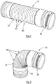
- FIGS. 1 , 2 and 3 showing perspective views of a toilet pan waste connector kit, generally depicted by reference numeral 10 according to a first embodiment of the present invention.
- the connector kit 10 comprises a connector 12 and a fastener 30.
- the connector 12 comprises a toilet pan waste outlet connection portion 20, a conduit portion 40 and a waste pipe connection portion 50.
- the toilet outlet connection portion 20 is connected to the conduit portion 40 via a rigid annular portion 60 using a combination of an interference fit and a weld cap 62.
- the waste pipe connection portion 50 is connected to the conduit portion 40 via a rigid annular portion 70.
- the conduit portion is a flexible pipe of the type disclosed, for example, in US Patents 4,846,510 and 4,927,191 , and UK Patent 2,298,470 .
- the pipe is flexible, in that it may be flexed to create up to 180° bends, and may also be axially extended or contracted.
- the pipe wall is also configured such that deformation of the pipe tends to be retained.
- the toilet pan waste outlet connection portion 20 comprises a flexible sleeve 22.
- the sleeve 22 has a substantially cylindrical internal surface 24.
- the cylindrical surface 24 comprises a flared portion 26, easing insertion over the toilet pan waste outlet.
- the fastener 30 is located on the outer surface of the sleeve 22 with the aid of sleeve ribs 28, which help maintain a longitudinal position of the fastener 30 on the sleeve 22 and ensure that a plane defined by the circumference of the fastener 30 is perpendicular to the longitudinal axis of the sleeve 22.
- the fastener 30 is a worm drive hose clip, however it will be understood that the fastener 30 could equally be selected from the following exemplary groups: tie wraps, strapping, belts.
- the fastener 30 can be tightened or loosened using a screw 32. Tightening the screw 32 decreases the internal diameter of the fastener 30, causing the fastener 30 to circumferentially compress the sleeve 22.
- the sleeve 22 is made from a soft synthetic rubber such that the sleeve 22 deforms under compression from the fastener 30.
- the internal surface 24 of the sleeve 22 is radially pressed against the outer surface of the toilet pan waste outlet such that a cylindrical contact surface seals the connection of the waste outlet to the connector 12.
- the waste pipe connection portion 50 comprises a flexible member 52.
- the flexible member 52 is made from a soft synthetic rubber and has a number of flexible annular ribs 54 projecting outwards.
- the ribs 54 have an inner diameter less than the waste pipe and an outer diameter greater than the waste pipe, such that the ribs 54 flex upon insertion of the portion 50 into the waste pipe, ensuring a seal between the connector 12 and the waste pipe.
- the flexible portion 40 of the connector 12 comprises a number of corrugated ribs 42.
- the corrugated ribs 42 allow the length of the connector 12 to be adjusted.
- the corrugated ribs 42 also allow the connector 12 to bend as well as extend and are configured such that the flexible portion will retain its form when configured by an operator.
- the connector 12 may be used to connect, for example, a horizontal toilet pan waste outlet to a vertical waste pipe.
- Figure 4 illustrates the kit 10 of figures 1 , 2 and 3 connected to a toilet pan 80.
- the connector 12 is connected to the toilet pan waste outlet 82 by the sleeve 22.
- the sleeve 22 has been manipulated over the outlet 82 and secured in place by the fastener 30, forming a seal between the outlet 82 and the connector 12. Tightening of the fastener 30
- Figure 5 shows a cross section of a portion of the connector 12, including the sleeve 22 and part of the conduit portion 40.
- the sleeve ribs 28, the cylindrical surface 24 and a flared portion 26 of the sleeve are all shown.
- the flexible sleeve 22 has an annular disc 29 for attachment to the rigid annular portion 60.
- the rigid annular portion 60 comprises the weld cap 62 and an inner sleeve 64.
- the sleeve described has ribs for locating the fastener, this could be nodules or grooves or any other suitable geometry for locating the fastener.
- the conduit portion described is a flexible pipe with corrugated ribs, this could be another form of flexible pipe or a rigid pipe, for example.
Landscapes
- Engineering & Computer Science (AREA)
- General Engineering & Computer Science (AREA)
- Mechanical Engineering (AREA)
- Health & Medical Sciences (AREA)
- Life Sciences & Earth Sciences (AREA)
- Hydrology & Water Resources (AREA)
- Public Health (AREA)
- Water Supply & Treatment (AREA)
- Sanitary Device For Flush Toilet (AREA)
Applications Claiming Priority (3)
| Application Number | Priority Date | Filing Date | Title |
|---|---|---|---|
| GBGB0913380.2A GB0913380D0 (en) | 2009-07-31 | 2009-07-31 | Improved toilet pan connector |
| EP10742226.3A EP2459810B1 (fr) | 2009-07-31 | 2010-07-30 | Dispositif de fixation pour cuvette de toilette |
| PCT/GB2010/001445 WO2011012860A2 (fr) | 2009-07-31 | 2010-07-30 | Raccord de cuvette de toilettes perfectionné |
Related Parent Applications (1)
| Application Number | Title | Priority Date | Filing Date |
|---|---|---|---|
| EP10742226.3A Division EP2459810B1 (fr) | 2009-07-31 | 2010-07-30 | Dispositif de fixation pour cuvette de toilette |
Publications (1)
| Publication Number | Publication Date |
|---|---|
| EP3441537A1 true EP3441537A1 (fr) | 2019-02-13 |
Family
ID=41129439
Family Applications (2)
| Application Number | Title | Priority Date | Filing Date |
|---|---|---|---|
| EP10742226.3A Active EP2459810B1 (fr) | 2009-07-31 | 2010-07-30 | Dispositif de fixation pour cuvette de toilette |
| EP18177383.9A Withdrawn EP3441537A1 (fr) | 2009-07-31 | 2010-07-30 | Raccord de cuvette de toilettes amélioré |
Family Applications Before (1)
| Application Number | Title | Priority Date | Filing Date |
|---|---|---|---|
| EP10742226.3A Active EP2459810B1 (fr) | 2009-07-31 | 2010-07-30 | Dispositif de fixation pour cuvette de toilette |
Country Status (4)
| Country | Link |
|---|---|
| EP (2) | EP2459810B1 (fr) |
| ES (1) | ES2685096T3 (fr) |
| GB (1) | GB0913380D0 (fr) |
| WO (1) | WO2011012860A2 (fr) |
Families Citing this family (4)
| Publication number | Priority date | Publication date | Assignee | Title |
|---|---|---|---|---|
| WO2014176605A1 (fr) | 2013-04-26 | 2014-10-30 | Falcon Waterfree Technologies, Llc | Siphon hybride à injection d'eau |
| US10184235B2 (en) | 2013-05-28 | 2019-01-22 | Falcon Waterfree Technologies, Llc | Directional fluid inlet |
| US10182688B2 (en) | 2013-05-28 | 2019-01-22 | Falcon Waterfree Technologies, Llc | Splash-reducing and velocity-increasing cartridge exit |
| IT201800005457A1 (it) * | 2018-05-17 | 2019-11-17 | Tubazione idraulica |
Citations (15)
| Publication number | Priority date | Publication date | Assignee | Title |
|---|---|---|---|---|
| CH176576A (de) * | 1934-09-29 | 1935-04-30 | Renz Sen Gottlieb | Klosettanlage. |
| GB971721A (en) * | 1962-03-15 | 1964-10-07 | Albert John Sadler | Improvements in or relating to joints for pipe members |
| DE1233338B (de) * | 1963-04-13 | 1967-01-26 | Guenter Ziegler | Anschluss des Abflussstutzens eines Klosettbeckens an das Abflussrohr mittels eines elastischen Rohrkoerpers |
| DE2216678A1 (de) * | 1971-06-22 | 1973-01-11 | Phetco England Ltd | Verbindungsstueck aus elastischem kunststoff |
| GB1559645A (en) * | 1977-09-02 | 1980-01-23 | Lamaguchi S | Flexible joint assembly |
| US4224702A (en) * | 1977-05-26 | 1980-09-30 | Bretone Jr John | Plumbing apparatus |
| US4846510A (en) | 1983-04-22 | 1989-07-11 | Twentieth Century Companies, Inc. | Adjustable tubular wall structure for connectors and the like |
| US4927191A (en) | 1983-04-22 | 1990-05-22 | Twenthieth Century Companies, Inc. | Adjustable tubular wall structure for connectors and the like |
| FR2677688A1 (fr) * | 1991-06-11 | 1992-12-18 | Wirquin Plastiques Sa | Tube de raccordement pour cuvette de toilettes. |
| DE19501615A1 (de) * | 1995-01-20 | 1996-08-08 | Porsche Ag | Rohrelement aus elastischem Material |
| GB2298470A (en) | 1995-02-28 | 1996-09-04 | Dalatek Ltd | Flexible piping |
| JP2000328634A (ja) * | 1999-05-19 | 2000-11-28 | Inax Corp | 排水構造 |
| EP1655528A2 (fr) * | 2004-10-30 | 2006-05-10 | McALPINE & COMPANY LIMITED | Élément de liaison entre la cuvette des toilettes et le tuyau de descente. |
| WO2007023346A2 (fr) * | 2005-08-25 | 2007-03-01 | Coflex S.A. De C.V. | Ensemble bride flexible pour le raccordement de conduites et procedes de raccordement associes |
| WO2009001115A1 (fr) * | 2007-06-28 | 2008-12-31 | Mcalpine & Co. Ltd. | Raccord de cuvette de toilette pourvu d'une partie souple |
Family Cites Families (2)
| Publication number | Priority date | Publication date | Assignee | Title |
|---|---|---|---|---|
| DE863330C (de) * | 1951-02-10 | 1953-01-15 | Arnold Jaeger | Anschlussstueck fuer Klosetts, Spuelbecken u. dgl. |
| DE9414741U1 (de) * | 1993-11-24 | 1994-11-10 | Geberit Technik Ag, Jona | Anschlußvorrichtung für einen Sanitärartikel |
-
2009
- 2009-07-31 GB GBGB0913380.2A patent/GB0913380D0/en not_active Ceased
-
2010
- 2010-07-30 WO PCT/GB2010/001445 patent/WO2011012860A2/fr not_active Ceased
- 2010-07-30 ES ES10742226.3T patent/ES2685096T3/es active Active
- 2010-07-30 EP EP10742226.3A patent/EP2459810B1/fr active Active
- 2010-07-30 EP EP18177383.9A patent/EP3441537A1/fr not_active Withdrawn
Patent Citations (15)
| Publication number | Priority date | Publication date | Assignee | Title |
|---|---|---|---|---|
| CH176576A (de) * | 1934-09-29 | 1935-04-30 | Renz Sen Gottlieb | Klosettanlage. |
| GB971721A (en) * | 1962-03-15 | 1964-10-07 | Albert John Sadler | Improvements in or relating to joints for pipe members |
| DE1233338B (de) * | 1963-04-13 | 1967-01-26 | Guenter Ziegler | Anschluss des Abflussstutzens eines Klosettbeckens an das Abflussrohr mittels eines elastischen Rohrkoerpers |
| DE2216678A1 (de) * | 1971-06-22 | 1973-01-11 | Phetco England Ltd | Verbindungsstueck aus elastischem kunststoff |
| US4224702A (en) * | 1977-05-26 | 1980-09-30 | Bretone Jr John | Plumbing apparatus |
| GB1559645A (en) * | 1977-09-02 | 1980-01-23 | Lamaguchi S | Flexible joint assembly |
| US4846510A (en) | 1983-04-22 | 1989-07-11 | Twentieth Century Companies, Inc. | Adjustable tubular wall structure for connectors and the like |
| US4927191A (en) | 1983-04-22 | 1990-05-22 | Twenthieth Century Companies, Inc. | Adjustable tubular wall structure for connectors and the like |
| FR2677688A1 (fr) * | 1991-06-11 | 1992-12-18 | Wirquin Plastiques Sa | Tube de raccordement pour cuvette de toilettes. |
| DE19501615A1 (de) * | 1995-01-20 | 1996-08-08 | Porsche Ag | Rohrelement aus elastischem Material |
| GB2298470A (en) | 1995-02-28 | 1996-09-04 | Dalatek Ltd | Flexible piping |
| JP2000328634A (ja) * | 1999-05-19 | 2000-11-28 | Inax Corp | 排水構造 |
| EP1655528A2 (fr) * | 2004-10-30 | 2006-05-10 | McALPINE & COMPANY LIMITED | Élément de liaison entre la cuvette des toilettes et le tuyau de descente. |
| WO2007023346A2 (fr) * | 2005-08-25 | 2007-03-01 | Coflex S.A. De C.V. | Ensemble bride flexible pour le raccordement de conduites et procedes de raccordement associes |
| WO2009001115A1 (fr) * | 2007-06-28 | 2008-12-31 | Mcalpine & Co. Ltd. | Raccord de cuvette de toilette pourvu d'une partie souple |
Non-Patent Citations (1)
| Title |
|---|
| HUNTER PLASTICS LIMITED: "Plumbers bits - a guide to traps, WC connectors, wastes and accessories", WASTES, TRAPS WC CONNECTORS. AN ESSENTIAL GUIDE, HUNTER PLASTICS, GB, 1 October 2002 (2002-10-01), pages I,6 - 7, XP002997870 * |
Also Published As
| Publication number | Publication date |
|---|---|
| EP2459810B1 (fr) | 2018-06-13 |
| EP2459810A2 (fr) | 2012-06-06 |
| WO2011012860A3 (fr) | 2011-04-14 |
| WO2011012860A2 (fr) | 2011-02-03 |
| GB0913380D0 (en) | 2009-09-16 |
| ES2685096T3 (es) | 2018-10-05 |
Similar Documents
| Publication | Publication Date | Title |
|---|---|---|
| CN107524872B (zh) | 软管端部适配器和软管组件、软管装置及相关制造方法 | |
| US20220042628A1 (en) | Pre-assembled coupling assembly with flexible hose adapter | |
| CN104930273B (zh) | 用于管耦接件的密封件 | |
| US7284310B2 (en) | Method of manufacturing a seal and restraining system | |
| CN101561067B (zh) | 软管连接方法和连接装置 | |
| KR101409306B1 (ko) | 2개의 경질 물체를 연결하기 위한 장치 | |
| US20040183302A1 (en) | Multi-diameter tube coupling | |
| EP2703705A1 (fr) | Système d'étanchéité pour un espace annulaire | |
| EP2443374B1 (fr) | Système de raccord instantané pour tuyauterie doté d'un manchon de support | |
| WO2008085633A2 (fr) | Raccord de transition rainuré | |
| US9080704B2 (en) | Universal pipe coupler | |
| EP3553362B1 (fr) | Appareil de raccordement de tuyaux à action rapide | |
| EP3441537A1 (fr) | Raccord de cuvette de toilettes amélioré | |
| JP5917198B2 (ja) | 伸縮可撓式継手とこれを用いたサドル付分水栓 | |
| WO2002042672A3 (fr) | Raccords de tuyau ou de conduit ou raccords d'extremite | |
| EP1800047B1 (fr) | Raccord de tuyaux | |
| KR20200123142A (ko) | 배관 연결 형성 장치 및 그 사용 방법 | |
| GB2606270A (en) | A support sleeve and a method of manufacturing a support sleeve | |
| KR200467368Y1 (ko) | 관 접속구용 확장링을 포함하는 관 접속구 | |
| CN206449334U (zh) | 直通接头 | |
| WO2019211828A1 (fr) | Raccords de tuyaux et utilisations correspondantes | |
| WO2001090496A1 (fr) | Raccord pour le raccordement des parties terminales de tuyaux d'evacuation a paroi double | |
| JPH09250667A (ja) | 離脱防止管継手 |
Legal Events
| Date | Code | Title | Description |
|---|---|---|---|
| PUAI | Public reference made under article 153(3) epc to a published international application that has entered the european phase |
Free format text: ORIGINAL CODE: 0009012 |
|
| STAA | Information on the status of an ep patent application or granted ep patent |
Free format text: STATUS: THE APPLICATION HAS BEEN PUBLISHED |
|
| AC | Divisional application: reference to earlier application |
Ref document number: 2459810 Country of ref document: EP Kind code of ref document: P |
|
| AK | Designated contracting states |
Kind code of ref document: A1 Designated state(s): AL AT BE BG CH CY CZ DE DK EE ES FI FR GB GR HR HU IE IS IT LI LT LU LV MC MK MT NL NO PL PT RO SE SI SK SM TR |
|
| STAA | Information on the status of an ep patent application or granted ep patent |
Free format text: STATUS: REQUEST FOR EXAMINATION WAS MADE |
|
| 17P | Request for examination filed |
Effective date: 20190813 |
|
| RBV | Designated contracting states (corrected) |
Designated state(s): AL AT BE BG CH CY CZ DE DK EE ES FI FR GB GR HR HU IE IS IT LI LT LU LV MC MK MT NL NO PL PT RO SE SI SK SM TR |
|
| STAA | Information on the status of an ep patent application or granted ep patent |
Free format text: STATUS: THE APPLICATION IS DEEMED TO BE WITHDRAWN |
|
| 18D | Application deemed to be withdrawn |
Effective date: 20220201 |