EP3441668A1 - Recouvrement de brûleur, procédé de fabrication d'un recouvrement de brûleur ainsi que brûleur de surface - Google Patents
Recouvrement de brûleur, procédé de fabrication d'un recouvrement de brûleur ainsi que brûleur de surface Download PDFInfo
- Publication number
- EP3441668A1 EP3441668A1 EP18186805.0A EP18186805A EP3441668A1 EP 3441668 A1 EP3441668 A1 EP 3441668A1 EP 18186805 A EP18186805 A EP 18186805A EP 3441668 A1 EP3441668 A1 EP 3441668A1
- Authority
- EP
- European Patent Office
- Prior art keywords
- burner
- cover
- burner cover
- area
- measuring
- Prior art date
- Legal status (The legal status is an assumption and is not a legal conclusion. Google has not performed a legal analysis and makes no representation as to the accuracy of the status listed.)
- Withdrawn
Links
Images


Classifications
-
- F—MECHANICAL ENGINEERING; LIGHTING; HEATING; WEAPONS; BLASTING
- F23—COMBUSTION APPARATUS; COMBUSTION PROCESSES
- F23D—BURNERS
- F23D14/00—Burners for combustion of a gas, e.g. of a gas stored under pressure as a liquid
- F23D14/12—Radiant burners
- F23D14/14—Radiant burners using screens or perforated plates
- F23D14/145—Radiant burners using screens or perforated plates combustion being stabilised at a screen or a perforated plate
-
- F—MECHANICAL ENGINEERING; LIGHTING; HEATING; WEAPONS; BLASTING
- F23—COMBUSTION APPARATUS; COMBUSTION PROCESSES
- F23D—BURNERS
- F23D2203/00—Gaseous fuel burners
- F23D2203/10—Flame diffusing means
- F23D2203/102—Flame diffusing means using perforated plates
- F23D2203/1023—Flame diffusing means using perforated plates with specific free passage areas
-
- F—MECHANICAL ENGINEERING; LIGHTING; HEATING; WEAPONS; BLASTING
- F23—COMBUSTION APPARATUS; COMBUSTION PROCESSES
- F23D—BURNERS
- F23D2203/00—Gaseous fuel burners
- F23D2203/10—Flame diffusing means
- F23D2203/103—Flame diffusing means using screens
-
- F—MECHANICAL ENGINEERING; LIGHTING; HEATING; WEAPONS; BLASTING
- F23—COMBUSTION APPARATUS; COMBUSTION PROCESSES
- F23D—BURNERS
- F23D2203/00—Gaseous fuel burners
- F23D2203/10—Flame diffusing means
- F23D2203/106—Assemblies of different layers
-
- F—MECHANICAL ENGINEERING; LIGHTING; HEATING; WEAPONS; BLASTING
- F23—COMBUSTION APPARATUS; COMBUSTION PROCESSES
- F23D—BURNERS
- F23D2212/00—Burner material specifications
- F23D2212/20—Burner material specifications metallic
- F23D2212/201—Fibres
-
- F—MECHANICAL ENGINEERING; LIGHTING; HEATING; WEAPONS; BLASTING
- F23—COMBUSTION APPARATUS; COMBUSTION PROCESSES
- F23D—BURNERS
- F23D2213/00—Burner manufacture specifications
Definitions
- the invention relates to a fiber-based burner cover for a surface burner, comprising a measuring area and a main area separated from the measuring area.
- the invention also relates to a method for producing a fiber-based burner cover for a surface burner and a surface burner, comprising a burner plate and a fiber-based burner cover according to the present invention and / or produced by a method according to the present invention.
- a fiber-based burner cover for a surface burner comprises a measuring area and a main area separated from the measuring area. It is envisaged that an ionization current of a flame of the surface burner is measured in the measuring range.
- the burner cover is characterized in that the burner cover at least in a part of the measuring range has a more uniform structure than the main area.
- the flames are uniform in the measuring range.
- the flames in the measuring range have a uniform height.
- an ionization current detected in the measuring range has a largely uniform value. To this The ionization current can be detected precisely.
- the burner control is improved and the surface burner is more economical and environmentally friendly operable.
- a “surface burner” is to be understood as meaning a component of a heating system which is provided for combustion of a fuel-air mixture.
- the surface burner is supplied with the fuel-air mixture.
- the surface burner fuel and air are supplied and mixed together, for example in a mixing chamber.
- a burner surface of the surface burner has a flame area at which the fuel-air mixture burns with a flame.
- the fuel-air mixture is supplied to the burner surface via a burner plate.
- the "burner plate” is a perforated plate, in particular made of metal. The burner plate serves for uniform distribution of the fuel-air mixture in the flame area.
- a "burner cover” is to be understood as meaning a structure which largely covers the burner plate and at least partially has the flame region of the burner surface.
- the burner cover is permeable to the fuel-air mixture.
- the burner cover is provided for advantageously influencing the combustion of the fuel-air mixture.
- the burner cover may cool the flames and / or affect flame formation, particularly with regard to flame geometry. In this way, optimized combustion, in particular with minimized pollutant emissions, can be ensured.
- a “fiber-based burner cover” is understood to mean a burner cover which is at least partially made of a fiber-based material.
- the fiber-based material consists of one or more fibers.
- the fiber-based material or the burner cover is planar or a thickness of the fiber-based material is significantly smaller compared to a length and width of the fiber-based material.
- the fiber or fibers consist of a substantially temperature-resistant material, such as metal, preferably stainless steel, and / or a ceramic and / or a mineral and / or a composite material.
- the burner cover or the fiber-based material may be made of a fiber-based yarn.
- a "yarn" is to be understood as meaning a largely linear structure of one or more fibers.
- a fiber-based material may be structured, preferably made of a yarn, for example a woven material, a braided material or a material Knitted fabric, in particular a knitted fabric, a crocheted material or a knitted material.
- a fiber-based material may be unstructured, for example a felt or a nonwoven.
- Heating system is to be understood as at least one device for generating heat energy, in particular a heating device or heating burner, in particular for use in a building heating system and / or for hot water generation, preferably by the combustion of a gaseous or liquid fuel.
- a heating system can also consist of several such devices for generating heat energy and other, the heating operation supporting devices, such as hot water and fuel storage.
- An operation of the heating system is preferably checked by means of a monitoring electrode, for example an ionization electrode, and optionally regulated.
- the monitoring electrode is provided for determining the quality of combustion.
- a fuel-air ratio or a lambda value of the fuel-air mixture can be determined in this way.
- the fuel-air mixture is at least partially ionized and has a conductivity which can be measured with the aid of the monitoring electrode or ionization electrode and is made available to a control unit of the heating system. This can be done a control of the fuel-air ratio or the composition of the fuel-air mixture.
- the “measuring range” is an area on the burner plate or on the burner cover, which is in spatial proximity to the monitoring electrode.
- the fuel-air mixture flowing out of the measuring area burns with a flame or flames which can be detected by the monitoring electrode. It is possible that the burner cover unfavorably affects the flame for detection by the monitor electrode.
- the burner cover has a more homogeneous structure than a main area at least in a part of the measuring area. In this way it is ensured that the flames are measurable in a sufficient quality by the monitoring electrode.
- the area of the burner plate or burner cover in which flames form which can not be detected by the monitoring electrode is called the "main area".
- an area of the main area is larger than an area of the measuring area.
- the burner cover in the main area has a less homogeneous structure than in the measuring area.
- the flames in the main area are unevenly shaped according to a random distribution. In this way, resonant effects are avoided, so that the surface burner is particularly quiet and safe to operate.
- a part of the measuring range in which at least the burner cover has a more uniform structure than the main area is to be understood as a partial area of the measuring area, preferably a coherent partial area.
- the part of the measuring range is so large and positioned in the measuring range that the flames arising in the part of the measuring range have a significant, preferably majority influence on the measured value detected by the ionization electrode.
- the area of the part of the measuring area is preferably over 50% of the total area of the measuring area, advantageously over 75%, particularly advantageously over 90%.
- the part of the measuring range corresponds to the measuring range.
- the uniformity of the structure of the burner cover may vary evenly, continuously, steadily or suddenly between the partial area of the measuring area and the main area.
- uniform structure is to be understood that the burner cover in the considered area is constructed substantially uniform, preferably with largely periodically arranged or regular structures.
- a fiber-based burner cover has an at least partially random, three-dimensional structure, in particular on a scale of a fiber size, in particular a fiber thickness, due to a statistical distribution of the fibers. It is advantageous to use statistical and / or averaged comparative variables for detecting or describing the structure or the uniformity of the structure, for example a density or an average thickness of the burner cover. For example, the density or average thickness in fixed surface areas of the burner cover can be detected.
- the burner cover can be divided into substantially uniform surface areas, in each of which the comparison variable is determined, for example by a square grid.
- the structure of the burner cover is uniform, if the considered comparison quantity in the considered range is largely constant or deviates below a tolerance limit of a given value.
- the structure of the burner cover is more uniform in the measuring range or part of the measuring range than in the main range, if the reference quantity under consideration has lower fluctuations in the measuring range or part of the measuring range than in the main range.
- the burner cover structure is more uniform in the measuring area than in the main area when the density of the burner cover deviates less from a predetermined value in squared surface areas of the measuring area than the density of the burner cover in the square area areas of the main area.
- the burner cover is further improved when a surface height on a flame side of the burner cover at least in part of the measuring range by less than 0.8 mm, preferably 0.4 mm, particularly preferably 0.1 mm, in particular the surface height by measuring with a substantially spherical probe with a diameter between 0.5 mm and 2.0 mm, preferably between 1.0 mm and 2.0 mm, preferably with substantially 1.5 mm, is determined.
- the surface of the burner cover is particularly even on the flame side. This has the advantage that a detected ionization current is particularly uniform in at least part of the measuring range.
- the ionisation electrode can detect a signal which is particularly reliable or low in fluctuation.
- surface height is meant a height of a flame-side surface of the burner cover.
- the surface height at a point on the surface of the burner cover is determined as the distance from any reference height.
- a substantially flat burner cover can be placed on a flat plate and the surface height defined at a point located on the surface of the burner cover as the vertical distance of the point to the flat plate.
- a curved burner cover can be placed and / or attached to a smooth sheet having a substantially similar curvature as the burner cover and the surface height defined at a point located on the surface of the burner cover as the vertical distance of the point from the sheet.
- a variation of the surface height in a surface area of the burner cover is a measure of roughness of the surface area.
- the variation of the surface height is a measure of how rugged the considered surface area is. If one considers a given section of the surface on the burner cover, for example a square projected onto the surface, the effective surface area available due to the three-dimensional topology of the cover surface is greater the larger the variation of the surface height is.
- the ionization current of the flame depends on the effective area on the burner cover. With a strong variation of the surface height in the measuring range, the ionization current of the flame will vary widely. This results in a poorer quality of the signal detected by the ionization electrode.
- the "surface height variation” is determined by determining two or more surface height values at two or more different points on the surface of the burner cover at least in a part of the measurement range. Subsequently, it can be checked how much the ascertained values of the surface height deviate from a given reference value for the surface height.
- the values are determined in points regularly arranged on the surface of the burner cover, for example arranged in the manner of a grid, preferably on a square grid.
- a possible measure of the variation is the mean square deviation of the values determined from the reference value. It is also conceivable that an average value is determined from the determined values of the surface height and it is checked how much the values of the surface height deviate from the mean value, for example with the aid of a standard deviation.
- the surface height is determined by means of a substantially spherical probe with a diameter between 0.5 mm and 2.5 mm, preferably between 1.0 mm and 2.0 mm, preferably with substantially 1.5 mm.
- the at least partially random, three-dimensional structure of the burner cover can be taken into account by the statistical distribution of the fibers.
- random deviations and fluctuations of an order of magnitude below the diameter of the probe can be averaged out. For example, it can be ensured in this way that a single fiber protruding from a yarn is not detected.
- the substantially spherical probe is lowered along the surface normal of the burner cover to a point of the burner cover. Once the probe has sufficient contact with the burner cover, the probe stops and its position determines the surface height. For example, it is conceivable that a voltage is applied between the probe and the burner cover and the probe stops when a sufficiently high current flows. It is also conceivable that the probe detects a mechanical force acting on it or a pressure. The probe stops as soon as the burner cover has a predetermined force or pressure on the probe. In this way, for example, a single fiber can be pressed down through the probe. From a certain number of fibers, the force acting on the probe exceeds the predetermined force to stop the probe and to determine the surface height.
- the probe is pressed onto the surface with a predetermined force.
- the probe is pulled laterally over the surface or parallel to the surface.
- the deflections of the probe are detected.
- a profile of the surface height determined along a line.
- the surface height can be detected by the probe line by line along a grid.
- the surface height can be determined with a profilometer, in particular a tactile profilometer or a contactless profilometer, for example an optical profilometer.
- a profilometer in particular a tactile profilometer or a contactless profilometer, for example an optical profilometer.
- optical profilometers are a laser profilometer or a white light interferometer.
- the burner cover has a largely constant mass density over at least part of the measuring range
- the burner cover is at least partially subdividable into surface areas of 4 cm 2 area, preferably 2 cm 2, more preferably 0.5 cm 2, at least in part of the measuring area and the surface areas each have a mass area density that differs by less than 15%, preferably less than 10%, more preferably less than 5% from a predetermined reference mass area density, this has the advantage that the mass of the burner cover in a part of the measuring range is distributed evenly.
- a largely constant mass density is a measure of a uniform structure of the burner cover. With a largely constant mass density, a largely constant flow resistance of the burner cover for a gas or for a fuel-air mixture is possible. This allows a particularly precise signal of the ionization electrode.
- a burner plate arranged on the burner cover burner plate is largely uniformly cooled by a burner cover with a substantially constant mass density. This allows a safe and reliable operation of a burner.
- the "surface areas" with 4 cm 2 area each, preferably 2 cm 2, more preferably 0.5 cm 2, are divided areas within the part of the measuring area, each of which has an area of 4 cm 2 or 2 cm ⁇ 2 or 0.5 cm ⁇ 2, if these areas are projected onto a plane parallel to the burner cover plane or smooth surface.
- the area of the surface areas is determined by the projection of the surface areas on a smooth surface that is as curved as the burner cover. Subdivision into the surface area can be done, for example, by projecting a regular square grid onto the burner cover.
- the surface of the burner cover Due to the statistical distribution of the fibers and at least partially random, three-dimensional structure of the burner cover has the surface of the burner cover in The surface areas generally have a different, in particular greater value than the surface area of the projected surface areas.
- the light transmission of the burner cover is substantially constant at least in part of the measuring range, in particular if the burner cover at least in part of the measuring range completely in surface areas with 4 cm ⁇ 2 surface area, preferably 2 cm ⁇ 2, particularly preferably 0.5 cm ⁇ 2, is divisible and the surface areas each have a light transmission, which differs by less than 15%, preferably less than 10%, more preferably less than 5% from a predetermined reference light transmittance.
- the regularity of the burner cover structure can be estimated very quickly and easily.
- the light transmittance is a measure of a permeability or of gas or of a fuel-air mixture. In this way, a flow resistance for a gas or for a fuel-air mixture can be determined.
- the light transmittance can be advantageously determined in a transmitted light method or a reflected light method.
- the burner cover may be illuminated with a normalized light source located behind the burner cover, and the brightness measured from the front of the burner cover. It is also conceivable that the burner cover is deposited with a bright surface, illuminated from the front side and the brightness is measured from the front of the.
- a flow resistance of the burner cover is substantially constant at least in part of the measuring range, in particular if the burner cover at least in part of the measuring range completely in surface areas with 4 cm ⁇ 2 surface area , preferably 2 cm ⁇ 2, more preferably 0.5 cm ⁇ 2 is divisible and the surface regions each have a flow resistance which differs by less than 15%, preferably less than 10%, particularly preferably 5% from a predetermined reference flow resistance.
- the regularity of the flames occurring on the burner cover is particularly easy to estimate.
- a flame height correlates with the flow resistance.
- the flow resistance can be defined or determined, for example, by how much a gas pressure or gas throughput is reduced.
- the burner cover or a piece of the burner cover on an open end of a pipe with a defined diameter or a defined cross-sectional area preferably are arranged according to a surface area defined above, so that a gas flowing through the pipe can flow out only through the burner cover or the piece of the burner cover.
- the gas pressure in the pipe is brought to a predetermined value and the percentage pressure drop behind the burner cover or piece of burner cover is determined.
- a percentage change in gas flow rate for example, in units of liters per minute and per square centimeter, can be determined.
- the burner cover at least in a part of the measuring range has a smaller cover thickness than in the main area, preferably if the first burner cover at least in part of the measuring range a cover thickness between 0.2 mm and 1.5 mm, more preferably between 0.5 mm and 0.8 mm in particular if the burner cover is compressed in at least part of the measuring range. If the burner cover is compressed in at least part of the measuring range, the burner cover has a more even structure in this area. In particular, the burner cover has a more uniform surface structure or topography in this area.
- cover thickness is to be understood as meaning an average thickness in the considered range. Due to the random distribution of the fibers due to the random distribution of the fibers, the three-dimensional structure of the burner cover or due to the varying surface height, the local thickness of the burner cover varies.
- a non-compressed burner cover in particular of a knitted fabric, may have a mean cover thickness between 1.0 mm to 2.5 mm, in particular between 1.5 mm and 1.8 mm.
- the local thickness of the burner cover can vary between 0.3 mm and 1.5 mm by the value of the cover thickness, in particular between 0.6 mm and 0.8 mm.
- the compression reduces the variation in local thickness of the burner cover in the compressed area.
- the structure of the burner cover can be more uniform in at least part of the measuring range than in the main area ,
- cover openings is meant a permeable opening for a gas or a fuel-air mixture.
- Cover openings may be openings created in the material of the cover opening, for example drilled, punched, punched or lasered openings.
- Cover openings may be part of the structure of the cover opening material, for example stitches of a knit or openings that are part of a knit pattern.
- any two adjacent cover openings each have at least one opening distance between 1 mm and 10 mm from one another, preferably an opening distance between 3 mm and 8 mm, particularly preferably between 5 mm and 6 mm, the flames become particularly uniform, in particular the flame height.
- ionization electrodes are rod-shaped and have a diameter between about 1 mm and 10 mm, preferably between 3 mm and 8 mm, particularly preferably between 5 mm and 6 mm. If adjacent cover openings have an opening distance that largely corresponds to the order of magnitude of a size of the ionization electrode, preferably a smallest extension direction of the ionization electrode, the flames detected by the ionization electrode are largely homogeneous.
- the burner cover has a knit fabric, preferably largely made of stainless steel.
- a knitted fabric has the advantage that a burner plate arranged on the burner cover is cooled particularly efficiently or thermally isolated from the flame side. In this way, a low-emission combustion is possible and increases the life of the burner.
- a fabric largely made of stainless steel has the advantage that it is particularly durable.
- the "burner cover has a knit fabric” to understand that the burner cover is at least partially made of a knitted fabric.
- the burner cover can be made in several parts from several components, wherein at least one component consists of a knitted fabric.
- the burner cover is completely or largely completely made of a knitted fabric.
- the burner cover is "largely made of stainless steel", it is to be understood that the burner cover as the main component consists of stainless steel fibers, preferably a yarn of stainless steel fibers.
- the burner cover made of high temperature resistant stainless steel.
- the burner cover or the fabric of the burner cover preferably consists of at least 75%, advantageously at least 85%, particularly advantageously at least 95%, of stainless steel. In special designs, the burner cover or the fabric of the burner cover is made entirely of precious ray.
- the burner cover has a first knit pattern in at least part of the measuring area and has a second knit pattern in the main area, the first knit pattern having a more regular structure than the second knit pattern.
- the first knit pattern it is possible for the first knit pattern to have more and / or larger and / or more regularly arranged cover openings than the second knit pattern.
- the second knit pattern has a smoother surface on the flame side of the burner cover than the first knit pattern.
- the burner cover has a separately manufactured section in the measuring area, the section having a more regular structure than the burner cover in the main area, preferably a fiber-based section, in this way the structure of the burner cover is more uniform in a part of the measuring area than in the main area.
- the section may be a piece of fabric which is mounted in the measuring area.
- the portion is sheet-like.
- the section is thinner than the burner cover.
- a method for producing a fiber-based burner cover for a surface burner, in particular a burner cover according to the present invention comprising a measuring area and a main area separated from the measuring area, wherein it is provided that an ionisation current of a flame of the area burner is measured in the measuring area, characterized in that Burner cover at least in a part of the measuring range is machined so that the burner cover has a more uniform structure in the at least part of the measuring range than in the main area, has the advantage that a burner cover is provided with a simple and fast method, which improves the quality of the ionization electrode measurement of the surface burner.
- the inventive Burner cover produced by the processing or improvement of a commercial burner cover. This allows a particularly cost-effective production of the burner cover.
- burner cover is compressed at least in part of the measuring area, in particular by a stamp, this has the advantage that a structure which is more uniform in one part of the measuring area than in the main area is created in one method step, which can be carried out particularly quickly, simply and reliably.
- cover openings are produced at least in a part of the measuring area, in particular by mechanical piercing and / or by a laser, in particular by a punch with needles, this has the advantage that a structure which is more uniform in one part of the measuring area than in the main area is created in one method step , which is particularly fast, precise and reproducible feasible.
- Mechanical piercing, especially with needles is particularly inexpensive and easy.
- the needles have a diameter of the cover openings.
- the method is further improved if at least in a part of the measuring range in a burner cover arranged on the burner plate in a manufacturing step together with the production of the cover openings plate opening in the burner plate are generated, in particular by mechanical piercing and / or by a laser.
- the cover openings and the plate openings can be pierced with a needle or generated in a laser cutting process.
- plate openings are meant a gas or a fuel-air mixture permeable openings in the burner plate.
- Plate openings may be openings made in the material of the burner plate, for example drilled, pierced, punched or lasered openings. Plate openings may be part of the structure of the cover opening material, for example openings of a grid.
- the burner cover is felted in at least part of the measuring range.
- the structure in a part of the measuring range can be changed so that it becomes much more uniform, in particular compared to the structure in the main area.
- felting is meant that the orientation of the fibers of the Burner cover is randomly distributed. It is particularly advantageous if the fibers at least partially interlock with one another due to the felting. The entanglement makes the arrangement of the fibers in the burner cover less orderly or more random than before.
- a locally ordered arrangement of the fibers for example in a yarn, can be disturbed. By disrupting locally ordered structures, the distribution of fibers in the burner cover is homogenized.
- a fiber-based burner cover by repeatedly rubbing the flame-side surface of the burner cover, particularly with a rough object, such as abrasive paper.
- a burner cover is felted by the repeated piercing of needles having a diameter on the order of the thickness of the fibers.
- the needles may have barbs which are intended to briefly detect individual or a few more fibers and thus to move or bend particularly strongly.
- the burner cover can be felted in deeper, inner layers.
- the burner cover can be compressed after rubbing or after piercing the needles. In this way, the fibers interlock even more closely.
- the burner cover is shaved at least in part of the measuring area or at least partially removes protruding fibers of the burner cover in at least part of the measuring area, the surface becomes more uniform in a part of the measuring area, in particular more uniform than in the main area. In this way, in particular, the variation of the surface height of the burner cover is reduced.
- This method is particularly advantageous for particularly hairy or many projecting fiber having burner covers.
- the protruding fibers can be shaved or severed, in particular by mechanical cutting, in particular with a blade. It is also conceivable that the protruding fibers are separated by heating, for example with a flame. By heating, the protruding fibers become brittle and can be broken off, for example, by a plate which is pressed against the burner cover.
- a surface burner comprising a burner plate and a fiber-based burner cover according to the present invention or with a fiber-based burner cover manufactured in a method according to the present invention has the advantage that the reliability and life of the surface burner is increased.
- the fact that the burner cover can largely cool the entire burner plate will damage it the burner plate avoided.
- the burner plate can be cooled in the measuring range, so that damage can be largely avoided by an uneven temperature distribution on the burner plate.
- FIG. 1 schematically components of a heater.
- the heater is controlled by means of a detected ionization current.
- the components essential for combustion control of the heater are shown.
- the heater includes other components, not shown, such as a heat exchanger, pumps, or an exhaust system. The type and number of components depends on the equipment level of the heater.
- FIG. 1 shows a surface burner 10, a blower 12, a doser 14, an ionisationselektrode 16 and a control unit 18.
- the surface burner 10 has a flame 20.
- the ionisation probe 16 protrudes into the flame 20.
- the blower 12 is intended to convey an air flow 24.
- a blower speed of the blower 12 is variably adjustable.
- the metering device 14 is designed as a combustor valve.
- the doser 14 is intended to deliver a fuel stream 26.
- the doser 14 is intended to adjust a quantity of fuel.
- the heater includes a supply unit 28.
- the supply unit 28 includes an airway.
- the airway is intended to guide the airflow 24.
- the supply unit 28 further includes a fuel path.
- the fuel path is intended to guide the fuel stream 26.
- the supply unit 28 includes a fuel-air mixture flow path.
- the fuel-air mixture flow path is intended to mix the airflow 24 with the fuel stream 26.
- the fuel-air mixture flow path is intended to lead a mixture stream 30, in particular a fuel-air mixture stream.
- the fuel-air mixture flow path or the supply unit 28 is provided in particular for supplying the mixture burner 30 to the surface burner 10.
- the control unit 18 has a data memory and a computing unit.
- the control unit 18 is connected via cables or bus lines 22 to the components of the heater, in particular to the blower 12, the metering device 14 and the ionization electrode 16.
- the control unit 18 is provided to regulate the air flow 24, in particular the control unit 18 is provided for this purpose to set the blower speed of the blower 12.
- the control unit 18 is provided to regulate the fuel flow 26, in particular by controlling the metering 14. By controlling the air flow 24 and the fuel flow 26, it is in particular possible, a fuel-air ratio of the fuel-air mixture stream 30 and to adjust the fuel-air mixture.
- the fuel-air ratio is also referred to as lambda value.
- the control unit 18 is intended to receive measured values from the ionization electrode 16.
- the ionization electrode 16 measures an ionization current. By substantially uniform properties of the flames 20, a precise and reliable detection of the ionization current through the ionization electrode 16 is possible.
- the heater is controlled in dependence on a lonisationsstromsollwert.
- the ionization current setpoint specifies the value which the ionization current should assume.
- the lonisationsstromsollwert is determined in dependence on the fan speed by the control unit 18.
- In the control unit 18 is a Flame ionization characteristic stored.
- the flame ionization curve assigns the appropriate ionization current setpoint to the fan speed.
- the flame ionization characteristic curve is determined empirically by laboratory experiments.
- the control unit 18 controls the metering device 14 or the fuel valve so that the ionization current assumes the value of the ionization current setpoint.
- a closed loop is used in the embodiment, wherein the ionization is a control variable, a control signal to the doser 14 and to the fuel valve is a control variable and the ionisationsstromsoll is a reference variable.
- FIG. 2 shows the surface burner 10 in a perspective view.
- FIG. 3 shows a section through a burner cover 34 of the surface burner 10.
- the burner cover 34 covers a burner plate 36 from.
- the burner plate 36 largely consists of a metal sheet.
- the burner plate 36 is designed as part of a metallic hollow body.
- the hollow body has a connection for the feed unit 28.
- the fuel-air mixture can flow into the hollow body.
- the burner plate 36 has a plurality of plate openings 38. The fuel-air mixture can flow out of the burner plate 36 through the plate openings 38.
- the burner cover 34 is disposed on the burner plate 36.
- the burner cover 34 is a knitted fabric.
- the burner cover is made of a yarn made of stainless steel fibers.
- the burner cover 34 is connected to the burner plate 36 by a plurality of welding points.
- the burner cover 34 may be secured to the burner plate 36 by other attachment methods.
- the attachment of the burner cover 34 to the burner plate 36 by staples, screws, rivets, welding, in particular resistance welding or laser welding, as well as soldering, gluing and / or clinching done.
- the choice of the method for fastening depends in particular on the properties of the burner cover 34 and / or the burner plate 36, in particular of which material the burner cover 34 and / or the burner plate 36 are made. It is conceivable that the burner cover 34 is attached to the burner plate 36 at different locations by a different method.
- the air flow 24 and the fuel stream 26 are supplied to the hollow body having the burner plate 36.
- the airflow 24 and fuel stream 26 mix within the hollow body.
- a measuring range 40 is shown on the burner cover 34 or on the burner plate 36.
- An edge 44 separates the measuring area 40 from the main area 42.
- the ionisation electrode 16 is arranged on the measuring area 40 (see FIG FIG. 4 ).
- the burner cover 34 has a more uniform structure in the measuring area 40 than in the main area 42.
- a surface height 46 varies less in the measuring area 40 than in the main area 42.
- a first variation 48 of the surface height 46 in the measuring area 40 is 0.3 mm.
- a second variation 50 of the surface height 46 in the main region 42 is 0.6 mm. Variation is a measure that describes how much the surface height 46 changes in a given range.
- the local surface height 46 at different locations or a position on the cover surface 52 of the burner cover 34 in the predetermined range is determined several times.
- the area may be, in particular, the measuring area 40 or the main area 42.
- the local surface height 46 is determined in points uniformly arranged on the cover surface 52, for example on a rectangular grid. It is also possible for the local surface height 46 to be determined such that a largely continuous dependence of the surface height 46 on the location is determined, for example when a probe is pulled along a path in the area or when measured by non-contact, in particular optical, profilometers.
- largely continuous dependence on location is meant a discrete dependence on location where the distances of the discrete points are very small.
- the distances of the discrete points are due to technical properties and / or physical laws that make a continuous measurement in the mathematical sense impossible, in particular by measurement inaccuracies in the location measurement. It is conceivable that the largely continuous dependence of surface height on location is described by analytical functions.
- the local surface height 46 is determined using a largely spherical probe with a diameter of 0.5 mm.
- the local surface height 46 is determined in each case on a square grid on the cover surface 52 with an edge length of 1.0 mm.
- an average value is determined.
- the variation of the surface height in the given range is the standard deviation of the determined surface heights.
- the variation of the surface height 46 is a measure of how much the local surface height 46 varies.
- the standard deviation of the local surface heights 46 in the measurement area 40 defines the first variation 48.
- the local surface height 46 has a first mean 54.
- the standard deviation of the local surface heights 46 in the main area 42 defines the second variation 50 local surface height 46 a second average 56.
- the first variation 48 is a measure of how much the surface height 46 varies in the measuring area 40.
- the second variation 50 is a measure of how much the surface height 46 in the main region 42 varies.
- the fuel-air mixture flows out of the plate openings 38.
- the fuel-air mixture flows through the burner cover 34.
- the fuel-air mixture burns on the flame-side cover surface 52 and / or within the burner cover 34 near the cover surface 52 Flame formation is affected by the burner cover 34.
- the fiber-based combustion cover 34 influences a flame geometry and / or other combustion parameters of the flames 20.
- the flame geometry are a flame image, a flame length or flame shape or a flame shape.
- Examples of other combustion parameters are a flame temperature or a measure for lifting the flames 20 from the cover surface 52 or for seating the flames 20 on the cover surface 52.
- the burner plate 36 is protected from excessive temperatures.
- the ionization electrode 16 is attached to the measuring region 40 (not in FIG FIG. 3 shown, see FIG. 4 ).
- the ionization electrode 16 measures an ionization current.
- the statistical distribution of the fibers in the burner cover 34 and the at least partially random three-dimensional structure of the burner cover 34 has an effect on flame formation.
- the flame geometry has a statistical distribution due to the random structure of the burner cover 34, for example, the flame height varies depending on the location on the Cover surface 52.
- the flames 20 are as uniform as possible. The more uniform the flame geometry, the more uniform and reliable is the ionization current determined by the ionization electrode 16. The more irregular the flame geometry, the greater is a measurement error of the ionization electrode 16.
- the burner cover 34 has a smaller first variation 48 than the second variation 50 in the main area 42 in the measuring area 40, the flames 20 in the measuring area 40 are more homogeneous than in the main area 42 (see FIG FIG. 4 ). In this way, better or more accurate measurements are possible in the measuring area 40 by the ionization electrode 16 than in the main area 42.
- the cover surface 52 effectively in contact with the flames 20 in one area is greater, the greater the variation of the surface height 46 in this area, due to the three-dimensional topology of the cover surface 52.
- the ionization current determined by the ionization electrode 16 depends on the size of the cover surface 52 that is effectively in contact with the flames 20.
- the size of the cover surface 52 in contact with the flames 20 affects the number of trapped or neutralized positive ions of the flames 20.
- the greater the variation of the surface height 46 in the measurement region 40 the more the determined ionization current varies.
- the lower the variation of the surface height 46 in the measuring region 40 the better the quality of the signal detected by the ionization electrode 16.
- the first variation 48 is less than 0.8 mm, preferably less than 0.4 mm, particularly preferably less than 0.1 mm. It is advantageous if the first variation 48 is determined on the basis of measurement data which are determined using a largely spherical measuring probe with a diameter of between 0.5 mm and 2.5 mm, preferably between 1.0 mm and 2.0 mm, particularly preferably substantially 1.5 mm.
- the first variation 48 can be determined by measurement data, which are determined by a measurement method, the average values over surface regions with a diameter between 0.5 mm and 2.5 mm, preferably between 1.0 mm and 2.0 mm, particularly preferably with substantially 1.5 mm, respectively a spatial resolution between 0.5 mm and 2.5 mm, preferably between 1.0 mm and 2.0 mm, particularly preferably with substantially 1.5 mm.
- a first variation 48 of a burner cover 34 may be 0.5 mm when determined with a substantially spherical probe having a diameter of 2.0 mm and the first Variation 48 of the same burner cover 34 may be 0.8 mm when determined with a substantially spherical probe with a diameter of 1.0 mm.
- "Spatial resolution" of a measuring method is to be understood as a minimum length, whereby the measuring method makes structures which have a shorter length than the minimum length no longer detectable or resolvable. The greater the spatial resolution, the less details can be resolved or the less small structures can be detected.
- the local surface height 46 is largely determined at one point, for example by a height measurement with an optical system, in particular a laser, or a very thin probe, in particular a needle-shaped probe.
- a height measurement with an optical system in particular a laser
- a very thin probe in particular a needle-shaped probe.
- largely in one point is meant a measurement in a very small, punctiform surface area, wherein an extension of the surface area is specified within the framework of the technical and physical restrictions, in particular by a measurement inaccuracy of the measuring device.
- the surface height 46 varies less in the measurement area 40 than in the main area 42.
- the first variation 48 is smaller than the second variation 50.
- the first variation 48 is less than 75% of the second variation 50 less than 50% of the second variation 50, more preferably less than 25% of the second variation 50.
- the variation in a region is determined by determining the difference between a maximum local surface height 46 determined in the region and a minimum local surface height 46 determined in the region.
- the first variation 48 can be determined as the difference between a maximum local surface height 46 determined in the measurement area 40 and a minimum local surface height 46 determined in the measurement area 40.
- any other dimensions for the variation are also conceivable, in particular statistical measures, in particular dimensions, which are determined from the distribution of the total local surface heights 46 detected in the region.
- the Variation may be determined as a mean cubic deviation from the mean of the surface heights 46 or as an average magnitude deviation from the mean of the surface heights 46.
- the burner cover 34 has a largely constant mass surface density in the measuring region 40.
- the mass area density fluctuates or varies in the measuring range 40 by less than 15%.
- FIG. 5 shows a top view of the burner cover 34.
- the burner cover 34 has a cover width 58 of 90 mm.
- the burner cover 34 has a cover length 60 of 180 mm.
- the measuring area 40 has a measuring range width 62 of 20 mm.
- the measuring area 40 has a measuring range length 64 of 60 mm.
- On the burner cover 34 a square grid 66 is projected.
- the grid 66 has an edge length 68 of 1 cm.
- the grid 66 divides the burner cover 34 into surface areas 70 each with 1 cm ⁇ 2 surface area.
- the grating 66 is not a physical feature and serves to divide the burner cover 34 into the surface areas 70. Dividing the burner cover 34 into surface areas 70 allows a quantified description of the uniform structure of the burner cover 34. Due to the statistical distribution of the fibers in the burner cover 34 and the burner cover 34 with at least partially random, three-dimensional structure of the burner cover 34, it is convenient to describe the uniformity of the structure of the burner cover 34 by averaged quantities, such as mass density, such as mean sizes of the surface areas 70, such as a mass area density averaged over a surface area.
- the grid 66 or subdivision of the burner cover 34 into surface areas 70 may have any other shape, such as a rectangular grid or a hexagonal grid.
- the choice of the grating 66 or the subdivision of the burner cover 34 into surface regions 70 depends on the geometry or on the shape of the burner cover 34, particularly advantageously on the geometry or shape of the measuring region 40 or part of the measuring region 40 and Furthermore, it is advantageous if the choice of the grating 66 or the subdivision of the burner cover 34 into surface areas 70 depends on the size considered in the surface areas 70 for determining the size Uniformity of the structure of the burner cover 34 is low or easy to determine.
- the shape of the surface regions 70 is designed in such a way that the surface region 70 can be easily and reliably attached to a defined tube opening for determining a pressure drop.
- the mass surface density of the surface regions 70 in the measuring region 40 deviates by less than 15% from a reference mass surface density.
- the reference mass area density is a predetermined value and corresponds to 1.2 kg / m 2 in the exemplary embodiment.
- the reference mass area density depends on the choice of burner cover 34 or on the properties of the burner cover 34, in particular on a cover thickness 72 or on the materials used. Typical values for mass area densities, in particular reference mass area densities of fiber-based burner covers 34 are between 0.5 kg / m 2 and 5.0 kg / m 2.
- Mass density densities in particular reference mass surface densities of burner covers 34, which have a knit, are preferably between 1.0 kg / m 2 and 1.5 kg / m 2, more preferably between 1.1 kg / m 2 and 1.3 kg / m 2.
- the reference mass area density corresponds to the mass area density of the burner cover 34 averaged over the entire cover surface 52, that is to say over the measuring area 40 and the main area 42.
- the reference mass area density corresponds to the mass area density averaged over the measuring area 40.
- the intensity of the deviation of the mass surface density of the surface regions 70 from the reference mass surface density depends on the choice of the surface regions 70, in particular on the size or the projected surface area of the surface regions 70.
- the greater the surface areas 70 within the measuring area 40 the smaller the deviation of the mass area density of the surface areas 70 from the reference mass area density.
- the larger the surface areas 70 are predefined within the measuring area 40 the more the mass area density of the surface areas 70 feeds to the mass area density of the measuring area 40.
- the choice of small surface areas 70 is not advantageous, since inhomogeneities of the structure of the burner cover 34 have an excessive influence.
- the diameter of the surface regions 70 is larger, preferably substantially larger, than a characteristic size of the fibers of the burner cover 34, for example as a Fiber thickness, and / or as characteristic sizes of a yarn used in the burner cover 34, for example, a yarn thickness or a mesh size, if the burner cover 34 has a knitted fabric.
- the magnitude of the deviation in a size for determining the uniformity of the structure of the burner cover 34 depends on a reference quantity of the choice of the surface areas 70 or the choice of the subdivision the burner cover 34 in surface areas 70, in particular an area or diameter of the surface regions 70.
- the reference size corresponds to a value of the size, averaged over the measuring area 40 and / or main area 42 and / or over all or part of the covering surface 52, for determining the uniformity of the structure of the burner cover 34.
- Choosing too small surface areas 70 is not advantageous Inhomogeneities of the structure of the burner cover 34 have too much influence on the value of the size for determining the uniformity of the structure of the burner cover 34.
- the diameter of the surface regions 70 is greater, preferably substantially larger, than a characteristic size of the fibers of the burner cover 34, for example as a fiber thickness, and / or as characteristic sizes of a yarn used in the burner cover 34, for example a yarn thickness or mesh size, if the burner cover 34 has a knit fabric.
- the mass area density in each respective surface area 70 differs by less than 15% from the reference mass area density. In variants of the exemplary embodiment, the mass area density deviates by less than 10% in each respective surface area 70, preferably by less than 5%. In alternative embodiments, the standard deviation of the determined mass surface densities of the surface regions 70 is less than 15% of the reference mass surface density, preferably less than 10%, more preferably less than 5%. In other embodiments, any other measure of the deviation of the mass area densities in the surface areas 70 from the Reference mass area density can be used, in particular a measure, which is determined from the distribution of the mass density in the surface regions 70. By way of example, the mean square deviation or the mean cubic deviation or the average magnitude deviation of the mass surface densities in the surface regions 70 from the reference mass surface density can be determined.
- Another size for determining the uniformity of the structure of the burner cover 34 is a light transmittance of the burner cover 34.
- the burner cover 34 in the measuring area 40 has a substantially constant light transmittance. The light transmission varies in the measuring range 40 by less than 15%.
- a light transmission can be determined, for example, by the burner cover 34 and a portion of the burner cover 34 is illuminated with a light source with a defined luminosity and a defined spectrum. The luminosity of the light passing through the burner cover 34 is measured. When the burner cover 34 is completely translucent, the measured maximum luminance defines a light transmittance of 100%. If only a part of the maximum luminosity is measured, then the value of the light transmittance is the percentage of the measured luminosity at the maximum luminosity. If no light is transmitted through the burner cover 34, the luminance is 0%. For the detection of the light transmission of a part of the burner cover 34, for example the measuring area 40 or a surface area 70, it is conceivable that an aperture is used which transmits light only in the part of the burner cover 34.
- the mass area density of the surface areas 70 in the measuring area 40 deviates by less than 15% from a reference light transmittance.
- the reference light transmittance is a light transmission of the measurement region 40.
- the reference light transmittance is a light transmittance of the entire cover surface 52 or part of the cover surface 52.
- the light transmittance depends on the characteristics of the burner cover 34, particularly a cover thickness 72, of the structure the burner cover, in particular cover openings 82, or of the materials used.
- the light transmission depends on the choice of the light source, in particular its spectrum and the intensity or luminosity of the light source. Typical values of light transmission for a fabric and / or a fabric are between 20% and 60%, preferably between 30% and 40%.
- the light transmittance in each respective surface region 70 differs by less than 15% from the reference light transmittance. In variants of the exemplary embodiment, the light transmission in each respective surface region 70 deviates by less than 10%, preferably by less than 5%. In alternative embodiments, the standard deviation of the determined light transmittances of the surface regions 70 is less than 15% of the reference light transmittance, preferably less than 10%, more preferably less than 5%. In other embodiments, any other measure of the deviation of the light transmittances in the surface areas 70 from the reference light transmittance may be used, in particular a measure determined from the distribution of the light transmittances in the surface areas 70. For example, the mean square deviation or the mean cubic deviation or the average magnitude deviation of the light transmittances in the surface regions 70 from the reference light transmittance can be determined.
- Another variable for determining the uniformity of the structure of the burner cover 34 is a flow resistance of the burner cover 34.
- the burner cover 34 has a largely constant flow resistance in the measuring region 40.
- the flow resistance fluctuates or varies in the measuring range 40 by less than 15%.
- a flow resistance can be determined, for example, by attaching the burner cover 34 or part of the burner cover 34 to an open pipe end of a first pipe.
- An end piece of a second tube is attached to the tube end piece, so that the burner cover 34 or the part of the burner cover 34 is enclosed by the first tube and the second tube and a gas can flow from the first tube into the second tube and through the burner cover 34 and the part of the burner cover 34 flows.
- the first tube is flowed through uniformly at a defined speed by a gas.
- the gas pressure in the first pipe is regulated to a defined value.
- the gas pressure in the second tube is measured.
- the flow resistance is defined as 100% minus the percentage of the gas pressure detected in the second tube at the given gas pressure in the first tube.
- the flow resistance is 0%. If no pressure is measured in the second tube, the flow resistance is 100%.
- the flow resistance may be defined, for example, via a velocity drop or mass flow drop of a gas flowing through the burner cover 34 and the portion of the burner cover 34, respectively.
- the flow resistance of the surface regions 70 in the measuring region 40 deviates by less than 15% from a reference flow resistance.
- the reference flow resistance is a flow resistance of a particular surface area 70.
- the particular surface area 70 is largely arranged centrally in the measuring area 40.
- the reference flow resistance is a flow resistance of the measurement region 40 or the entire cover surface 52 or part of the cover surface 52.
- the flow resistance depends on the characteristics of the burner cover 34, in particular, a cover thickness 72, the structure of the burner cover, particularly cover openings 82 , or of the materials used.
- the flow resistance depends on the choice of the gas, in particular the chemical composition, as well as the choice of the gas pressure and a gas flow rate.
- a fuel-air mixture is used as gas for determining the flow resistance, which largely corresponds to a fuel-air mixture intended for operating the heater.
- gas pressure and gas flow velocity for determining the flow resistance values are used which typically occur in an operation of the heater.
- the flow resistance in each respective surface area 70 deviates by less than 15% from the reference flow resistance. In variants of the exemplary embodiment, the flow resistance in each respective surface area 70 deviates by less than 10%, preferably by less than 5%. In alternative embodiments, the standard deviation of the determined flow resistances of the surface regions 70 is less than 15% of the reference flow resistance, preferably less than 10%, more preferably less than 5%. In other embodiments, any other measure of the deviation of the flow resistance in the surface regions 70 from the reference flow resistance may be used, in particular a measure determined from the distribution of the flow resistances in the surface regions 70. For example, the mean square deviation or the mean cubic deviation or the average magnitude deviation of the flow resistances in the surface regions 70 from the reference flow resistance can be determined.
- the burner cover 34 has a smaller cover thickness 72 in the measuring area 40 than in the main area 42 (see FIG FIG. 3 ).
- the Burner cover 34 has a first cover thickness 76 of 1.5 mm.
- the first cover thickness 76 is defined as the distance of the first mean 54 of the surface height 46 to the burner side burner plate surface of the burner plate 36 (see FIG FIG. 3 ).
- the burner cover 34 has a second cover thickness 80 of 3.0 mm.
- the second cover thickness 80 is defined as the distance of the second average 56 of the surface height 46 to the flame-side burner plate surface.
- the first cover thickness 76 is between 0.2 mm and 1.5 mm, more preferably between 0.5 mm and 0.8 mm. It is advantageous if the burner cover 34 in the measuring area 40 or in a part of the measuring area 40 is compressed, so that the first cover thickness 76 is smaller than the second cover thickness 80. This has the advantage that a compressed portion of the burner cover 34 a more uniform structure than a non-compressed portion of the burner cover 34th
- FIG. 6 shows a plan view of a variant of the burner cover 34.
- the cover openings 82 are substantially circular.
- the cover openings 82 have an opening diameter of 1.5 mm.
- the cover openings 82 are in the in FIG. 6 illustrated variant in the burner cover 34 lasered openings.
- the cover openings 82 are in the in FIG. 6 mapped variant square in the measuring range 40. Adjacent cover openings 82 have an opening distance 84 of 10 mm from each other. In alternative embodiments, the cover openings 82 may be arbitrarily arranged in the measuring area. For example, the cover apertures 82 may be disposed on a rectangular grid, skewed grid, hexagonal grid centered-rectangular grid, or honeycomb grid. It is also conceivable that the cover openings are arranged on two or more different grids.
- cover openings 82 have different opening diameters.
- the cover openings 82 have two different opening diameters which are each arranged on two different grids.
- the main area 42 has cover openings 82.
- the cover openings 82 are preferably arranged more densely in the measuring area 40 than in the main area 42 or the cover openings 82 have a smaller one in the measuring area Opening distance 84 than in the main area 42. In this way it can be ensured that the structure of the burner cover 34 in the measuring area 40 is more regular than in the main area 42.
- the cover openings 82 are arranged on the plate openings 38 or in the vicinity of the plate openings 38.
- a favorable flow of the fuel-air mixture can be ensured.
- the surface burner 10 may have a particularly homogeneous flame pattern during operation.
- the burner cover 34 is made of a knitted fabric. In alternative embodiments, the burner cover 34 may at least partially comprise any other fiber-based material. For example, the burner cover 34 may at least partially comprise a woven material, a braided material, a felt, a nonwoven and / or a material of knitwear, in particular a knitted material, a crocheted material or a knit. In the exemplary embodiment, the burner cover 34 is made of a temperature-resistant stainless steel. Other materials are also conceivable, for example, the burner cover 34 may at least partially consist of a ceramic, a mineral, a composite and / or a metal, preferably a temperature-resistant metal or a metal alloy.
- the burner cover 34 has a first knitting pattern in the measuring area 40 or in a part of the measuring area 40, and a second knitting pattern in the main area 42.
- the first knit pattern has a more regular structure than the second knit pattern.
- the plain knit stitch pattern has the advantage that the first variation 48 can be particularly small.
- the first knit pattern has a different number of stitches per meter than the second knit pattern.
- the first knitting pattern has between 300 and 400 stitches per meter length, preferably between 320 and 380 stitches per meter length, more preferably between 340 and 360 stitches per meter length.
- the first knitting pattern has regularly arranged cover openings 82.
- the burner cover 34 comprises a woven material or is made of a woven material
- the first weave pattern has a more regular structure than the second weave pattern.
- the burner cover 34 has a knitted fabric or is made of a knitted fabric, it is advantageous if the burner cover 34 has a first knitting pattern in the measuring region 40 or in a part of the measuring region 40 and has a second knitting pattern in the main region 42.
- the first knitting pattern has a more regular structure than the second knitting pattern.
- the fiber-based burner cover 34 is at least partially made of a different yarn in the measuring region 40 than in the main region 42. It is particularly advantageous if the measuring area 40 has a yarn that is thinner than a yarn predominantly present in the main area 42.
- the burner cover 34 has a fleece and / or a felt or is made from a fleece and / or a felt, it is advantageous if the burner cover has a different fiber density in the measuring region 40 or in a part of the measuring region 40 than in the main region , It is also conceivable that bevels with a different fiber thickness or with a different fiber thickness distribution are present in the measuring area 40 or in the part of the measuring area 40 than in the main area.
- Typical values for a fiber thickness, in particular of stainless steel fibers are between 1 ⁇ m and 1 mm, preferably between 5 ⁇ m and 100 ⁇ m, particularly preferably between 15 ⁇ m and 20 ⁇ m.
- a “fleece” is meant a structure of fibers, preferably fibers of limited length.
- the fleece is largely unstructured or has a random structure on a scale of a fiber size.
- the fibers are arranged largely randomly or chaotically.
- a nonwoven may have to strengthen binder. It is possible that a thermal consolidation process is used in the manufacture of a nonwoven web, for example, metal fibers may be temporarily heated to such an extent that contacting fibers weld together at the points of contact.
- a fleece is sometimes referred to as a nonwoven or fiber mat.
- a "felt” is a special fleece in which a bond between the fibers, in particular by entanglement of the fibers among one another, is increased in the manufacturing process by mechanical processing.
- a felt can be produced by needling a nonwoven fabric. When needling repeated needles with barbs in the fleece stuck in and pulled out. In this way, the fibers entwine with each other. The entanglement of the fibers is largely unstructured or randomly distributed.
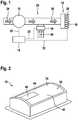
- the burner cover 34 has a separately manufactured section 86 in the measuring area 40 (see FIG FIG. 7 ).
- the portion 86 has a more regular structure than the burner cover 34 in the main area 42.
- the portion 86 is fiber-based, more preferably, the portion 86 has a knit fabric or is made of a knitted fabric. It is advantageous if the portion 86 is attached to the flame-side cover surface 52.
- the portion 86 is welded to the burner cover 34.
- the portion 86 is welded to the burner cover 34, soldered, glued, riveted, clinched, bolted clamped, tethered and / or sewn, especially with a fiber or a fiber-based yarn.
- the choice of the method for fastening depends in particular on the properties of the burner cover 34 and / or the portion 86, in particular of which material the burner cover 34 and / or the portion 86 are made.
- FIG. 7 shows a particularly preferred variant in which the burner cover 34 has a smaller cover thickness 72 in the measuring area 40 than in the main area 42.
- the portion 86 is mounted on the flame-side cover surface 52. The portion 86 has a smoother surface than the burner cover 34.
- the burner cover 34 has a recess in the measuring area 40 or in a part of the measuring area 40.
- the portion 86 is inserted into the recess and connected to the burner cover 34.
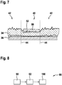
- FIG. 8 shows a method 88 for producing the burner cover 34 of the embodiment.
- the burner cover 34 is mounted on the burner plate 38.
- the burner cover 34 is welded to the burner plate 38.
- the burner cover 34 may be connected to the burner plate 36 by welding, soldering, gluing, riveting, clinching, screwing, clamping, tying, and / or sewing, particularly with a fiber or fiber-based yarn.
- the burner cover 34 is processed so that it has a more uniform structure in at least part of the measuring area 40 than in the main area 42.
- the burner cover 34 is placed together with the burner plate 36 on a base 94 (see FIG. 9 ).
- the base 94 is made of a hard and largely non-deformable, in particular not deformable by stamping material.
- the burner plate 36 is located between the burner cover 34 and the base 94.
- the burner cover 34 is at least partially compressed with a stamp 96.
- the stamp 96 is made of a hard and largely non-deformable, in particular not deformable by stamping material.
- a stamp foot 98 has substantially the same shape or geometry as the measuring area 40. Compressing the burner cover 34 with the stamp 96 reduces the cover thickness 72 of the burner cover 34 in the measuring area 40. How much the cover thickness 72 is reduced by the compression, depends on the material of the burner cover 34 and / or the contact pressure and the pressing force of the punch 96. Typical values of cover thicknesses 72 of a non-compressed fabric are between 1.0 mm to 3.0 mm, in particular between 1.5 mm and 1.8 mm.
- the cover thickness 72 or the first cover thickness 76 can be between 0.1 mm and 2.0 mm, preferably between 0.2 mm and 1.5 mm, particularly preferably between 0.4 mm and 1.0 mm.
- the burner plate 36 is connected together with the burner cover 34 with a metallic component.
- the burner plate 36 and the metallic component form the metallic hollow body.
- the metallic hollow body is an essential component of the surface burner 10.
- the burner plate 36 is connected to the metallic component by welding.
- the burner plate 36 may be connected to the metallic component by welding, soldering, gluing, riveting, clinching, screwing, and / or clamping.
- the base 94 is largely flat.
- the stamp 96 and the stamp foot 98 are formed largely flat.
- the pad 94 and / or the stamp 96 and the stamp foot 98 have a curvature.
- the pad 94 and the punch 96 and the punch 96 have a substantially same curvature.
- the base 94 and / or the stamp 96 have the stamp foot 98 advantageously has a curvature which largely corresponds to the curvature of the burner cover 34.
- the steps may be arbitrarily reversed. It is conceivable that first in a step 92, the burner cover 34 is processed so that the burner cover 34 at least in a part of the measuring area 40 has a more uniform structure than in the main area 42. For example, in step 92, the burner cover 34 may be placed on the pad 94 and then at least partially compressed with the plunger 96, in particular within the measuring area 40. In a subsequent step 90, the burner cover 34 is connected to the burner plate 36.
- step 100 is performed before step 90 and / or before step 92. This is particularly possible if the step 92 without pad 94 is executable. In particular methods, no step 100 is performed, for example, when the burner plate 36 having hollow body is in one piece and / or pre-assembled. It is also conceivable that the step 92 is performed after the step 90 and / or after the step 100. In particular, step 92, in which the burner cover 34 is machined to have a more uniform structure in at least a portion of the measuring area 40 than in the main area 42, may be performed after the area burner 10 is made completely wide, particularly after the burner cover 34 was attached to the burner plate 36 in a step 90. This has the advantage that already finished surface burners 10 can be improved in this way. For example, heaters can be retrofitted or optimized.
- cover openings 82 are created in burner cover 34 in at least part of measuring area 40.
- the cover openings 82 are produced with a laser cutting nozzle 102.
- the burner cover 34 may be fastened to the burner plate 36.
- FIG. 10 FIG. 12 shows step 92 wherein a cover opening 82 is cut into the burner cover 34 by a laser beam 104.
- the burner cover 34 is supported by a hold-down 106 on the pad 94 pressed.
- the hold-down 106 has a recess through which the laser beam 104 can cut the cover opening 82 into the burner cover 34.
- the burner cover 34 is connected to the burner plate 36 in step 90.
- the burner plate 36 has plate openings 38, so that the burner cover 34 can be connected to the burner plate 36 in step 90 such that the cover openings 82 lie above the plate openings 38.
- the plate openings 38 are larger than the cover openings 82, so that the burner cover 34 can be mounted on the burner plate 36 in a particularly reliable manner so that the cover openings 82 lie above the plate openings 38.
- the cover openings 82 may have a diameter of 1.0 mm.
- the plate openings may have a diameter of between 1.5 mm and 4.0 mm, preferably between 2.0 mm and 3.5 mm, particularly preferably between 2.5 mm and 3.0 mm.
- the hold-down 106 compresses the burner cover 34 in the region of the cover opening 82.
- the metallic, fiber-based material of the burner cover 34 at least partially melts at the inboard edge of the cover opening 82. In this manner, the burner cover 34 locally solidifies near the cover opening 82 in the compressed state.
- the local surface height 46 is largely permanently lowered in the region of the cover opening 82.
- the hold-down 106 compresses the burner cover 34 substantially in the complete measuring area 40 or in a part of the measuring area 40.
- the hold-down 106 has recesses at the locations where cover openings 82 are provided in the measuring area 40.
- step 92 first the burner cover 34 is compressed by the hold-down 106. Subsequently, the laser cutting nozzle cuts the intended cover opening 82 and the intended cover openings 82 into the burner cover 34. Thereafter, the hold-down 106 is removed from the burner cover 34. If necessary, further processing steps are then carried out.
- the cover openings 82 and the plate openings 38 are produced in a production step 92.
- step 90 is carried out beforehand.
- the FIGS. 11 and 12 show step 92, wherein the cover opening 82 in the Burner cover 34 and the plate opening 38 are cut into the burner plate 36 by the same laser beam 104.
- the burner cover 34 is located above the burner plate 36 so that the laser beam 104 strikes the burner cover 34 first and then the burner plate 36. As a result, higher temperatures occur at or in the burner cover 34 during cutting than at or in the burner plate 36.
- the burner cover 34 is disposed below the burner plate 36 so that the laser beam 104 strikes the burner plate 36 first and then the burner cover 34. As a result, lower temperatures occur at or in the burner cover 34 during cutting than at or in the burner plate 36.
- the choice of whether the burner cover 34 and burner plate 36 as in FIG. 11 or FIG. 12 are arranged, depends on the technical requirements. In particular, this choice depends on the materials from which the burner cover 34 and / or the burner plate 36 are made.
- the cover openings 82 may also be mechanically attached in step 92.
- the cover openings 82 are attached to the burner cover 34 with needles 107.
- FIG. 13 shows a punch 96, which needle 107 has.
- the burner cover 34 rests on a base 94.
- the pad 94 is a die for the punch 96 with needles 107.
- the burner plate 36 is attached on the burner cover 34.
- the burner plate 36 is disposed on the side of the punch 96.
- the needles 107 are arranged on the die foot 98 so that they can pierce the burner cover 34 through the plate openings 38 when lowered.
- the pad 94 has needle receptacles 108 which can receive the needles 107 as soon as they have penetrated the burner cover 34.
- This variant of the method 88 has the advantage that the cover openings 82 are reliably attached to the position of the plate openings 38.
- the burner cover 34 is pressed together with the needles 107 during the attachment of the cover openings 82 or when piercing the burner cover 34.
- the burner cover 34 is processed so that the burner cover 34 in the measuring area 40 and in a part of the measuring area 40 has a more uniform structure than in the main area 36 by cover openings 82 in the measuring area 40 or in a part of the measuring range 40 are attached and by the Burner cover 34 in the measuring area 40 or in a part of the measuring area 40 is compressed.
- the cover openings 82 are cut and / or punched in step 92 by a jet of water.
- the plate openings 38 are mounted with needles 107 in the burner plate 36.
- the plate openings 38 can be attached in the same manufacturing step as the cover openings 82 with needles 107.
- the burner cover 34 is previously attached to the burner plate 36 in a step 90.
- the burner cover 34 is entangled in the measuring area 40 or in a part of the measuring area 40.
- the felting is particularly advantageous if the material of the burner cover 34 has at least in the measuring region 40 or in a part of the measuring region particularly many individually projecting fibers.
- the burner cover 34 has at least in the measuring region 40 a woven fabric and / or a knitted fabric and / or a knitted fabric, which is made of a particularly hairy yarn.
- a "hairy yarn” is to be understood as meaning a yarn which has particularly many protruding fibers and / or has a comparatively low density of fibers. This has the advantage that the fabric and / or knitted fabric and / or knitted fabric can already be at least partially felted with a hairy yarn during the production process or already during weaving and / or knitting and / or knitting with a hairy yarn.
- the burner cover 34 is shaved in the measuring region 40 or in a part of the measuring region 40 in step 92 or fibers protruding in the measuring region 40 or in a part of the measuring region 40 are at least partially, preferably substantially completely removed.
- the burner cover 34 is first felted and then pressed together by a die 96, with or without needles 107. In this way, in addition, the entanglement of the burner cover 34 is further enhanced.
- step 92 first the burner cover 34 is pressed together with a stamp 96 and subsequently a section 86 is fastened in the compressed area.
Landscapes
- Engineering & Computer Science (AREA)
- Chemical & Material Sciences (AREA)
- Combustion & Propulsion (AREA)
- Mechanical Engineering (AREA)
- General Engineering & Computer Science (AREA)
- Control Of Combustion (AREA)
Applications Claiming Priority (1)
| Application Number | Priority Date | Filing Date | Title |
|---|---|---|---|
| DE102017213767.3A DE102017213767A1 (de) | 2017-08-08 | 2017-08-08 | Brennerabdeckung, Verfahren zur Herstellung einer Brennerabdeckung sowie ein Flächenbrenner |
Publications (1)
| Publication Number | Publication Date |
|---|---|
| EP3441668A1 true EP3441668A1 (fr) | 2019-02-13 |
Family
ID=63113439
Family Applications (1)
| Application Number | Title | Priority Date | Filing Date |
|---|---|---|---|
| EP18186805.0A Withdrawn EP3441668A1 (fr) | 2017-08-08 | 2018-08-01 | Recouvrement de brûleur, procédé de fabrication d'un recouvrement de brûleur ainsi que brûleur de surface |
Country Status (2)
| Country | Link |
|---|---|
| EP (1) | EP3441668A1 (fr) |
| DE (1) | DE102017213767A1 (fr) |
Citations (6)
| Publication number | Priority date | Publication date | Assignee | Title |
|---|---|---|---|---|
| JPS60155824A (ja) * | 1984-01-24 | 1985-08-15 | Matsushita Electric Ind Co Ltd | 酸欠安全装置 |
| EP0339499A2 (fr) * | 1988-04-28 | 1989-11-02 | Joh. Vaillant GmbH u. Co. | Dispositif de surveillance du fonctionnement de la plaque de brûleur d'un brûleur à panneaux |
| EP1036984A1 (fr) * | 1999-03-18 | 2000-09-20 | G. Kromschröder Aktiengesellschaft | Brûleur à prémélange gazeux |
| DE102005056499A1 (de) * | 2005-11-28 | 2007-05-31 | Schott Ag | Gasbrenner |
| EP2687781A2 (fr) * | 2012-07-17 | 2014-01-22 | Robert Bosch GmbH | Brûleur à platine et procédé de surveillance d'une formation de flammes pour une brûleur à platine |
| WO2014067744A1 (fr) * | 2012-10-31 | 2014-05-08 | Bekaert Combustion Technology B.V. | Brûleur à prémélange de gaz |
Family Cites Families (3)
| Publication number | Priority date | Publication date | Assignee | Title |
|---|---|---|---|---|
| ITMO20070167A1 (it) * | 2007-05-21 | 2008-11-22 | Worgas Bruciatori Srl | Bruciatore modulante |
| DE102014226060A1 (de) * | 2014-12-16 | 2016-06-16 | Robert Bosch Gmbh | Brennervorrichtung und Verfahren zur Optimierung einer Brennervorrichtung |
| DE202016105039U1 (de) * | 2016-09-12 | 2017-09-14 | Viessmann Werke Gmbh & Co Kg | Gasbrenner |
-
2017
- 2017-08-08 DE DE102017213767.3A patent/DE102017213767A1/de not_active Withdrawn
-
2018
- 2018-08-01 EP EP18186805.0A patent/EP3441668A1/fr not_active Withdrawn
Patent Citations (6)
| Publication number | Priority date | Publication date | Assignee | Title |
|---|---|---|---|---|
| JPS60155824A (ja) * | 1984-01-24 | 1985-08-15 | Matsushita Electric Ind Co Ltd | 酸欠安全装置 |
| EP0339499A2 (fr) * | 1988-04-28 | 1989-11-02 | Joh. Vaillant GmbH u. Co. | Dispositif de surveillance du fonctionnement de la plaque de brûleur d'un brûleur à panneaux |
| EP1036984A1 (fr) * | 1999-03-18 | 2000-09-20 | G. Kromschröder Aktiengesellschaft | Brûleur à prémélange gazeux |
| DE102005056499A1 (de) * | 2005-11-28 | 2007-05-31 | Schott Ag | Gasbrenner |
| EP2687781A2 (fr) * | 2012-07-17 | 2014-01-22 | Robert Bosch GmbH | Brûleur à platine et procédé de surveillance d'une formation de flammes pour une brûleur à platine |
| WO2014067744A1 (fr) * | 2012-10-31 | 2014-05-08 | Bekaert Combustion Technology B.V. | Brûleur à prémélange de gaz |
Also Published As
| Publication number | Publication date |
|---|---|
| DE102017213767A1 (de) | 2019-02-14 |
Similar Documents
| Publication | Publication Date | Title |
|---|---|---|
| DE69322622T2 (de) | Poröse metallfiber-platte | |
| EP2687781B1 (fr) | Brûleur à platine et procédé de surveillance d'une formation de flammes pour une brûleur à platine | |
| DE102010051414B4 (de) | Verbrennungsverfahren mit kühler Flammenwurzel | |
| DE102010051415B4 (de) | Verdrängungsverfahren bei der Herstellung einer Brennergewebemembrane für eine kühle Flammenwurzel | |
| DE102007019086A1 (de) | Brennervorrichtung | |
| DE102021125524A1 (de) | Flammensperre, Gasbrenner und Gasheizgerät | |
| DE4033296A1 (de) | Gasbrenner und verfahren zum betreiben eines solchen | |
| EP3221641A1 (fr) | Dispositif évaporateur | |
| EP2856027B1 (fr) | Procédé de combustion totale et à bruit réduit d'un mélange combustible-air, et brûleur correspondant | |
| EP4043793A1 (fr) | Procédé et agencement de détection d'un retour de flamme dans un brûleur à prémelange | |
| EP3441668A1 (fr) | Recouvrement de brûleur, procédé de fabrication d'un recouvrement de brûleur ainsi que brûleur de surface | |
| EP2928968B1 (fr) | Générateur de suie | |
| DE102015110829B4 (de) | Poröses Brennstoffaufbereitungselement | |
| EP4411224A1 (fr) | Procédé de fonctionnement d'un appareil de chauffage, programme informatique, appareil de régulation et de commande et appareil de chauffage | |
| DE202007019430U1 (de) | Gasgebläsebrenner | |
| EP2844920B1 (fr) | Brûleur à prémélange gazeux | |
| EP3372895A1 (fr) | Procédé de fabrication d'un brûleur en nappe ainsi que brûleur en nappe | |
| WO2010020203A2 (fr) | Brûleur à combustible liquide pour appareil de chauffage de véhicule | |
| EP3234463A1 (fr) | Système de brûleur et procédé permettant d'optimiser un système de brûleur | |
| DE102005011287A1 (de) | Verfahren sowie eine Vorrichtung zum Betreiben wenigstens eines Brenners zur Befeuerung der Brennkammer einer Wärmekraftmaschine | |
| EP4155611A1 (fr) | Procédé de détection de l'extinction d'une flamme d'un brûleur | |
| DE102021124683A1 (de) | Verfahren zur Erkennung des Erlöschens einer Flamme eines BrennersVerfahren zur Erkennung des Erlöschens einer Flamme eines Brenners | |
| DE3382640T2 (de) | Verfahren und vorrichtung zum gleichmaessigen trocknen bewegender baender. | |
| DE4115504C2 (fr) | ||
| DE102019218652A1 (de) | Brennervorrichtung |
Legal Events
| Date | Code | Title | Description |
|---|---|---|---|
| PUAI | Public reference made under article 153(3) epc to a published international application that has entered the european phase |
Free format text: ORIGINAL CODE: 0009012 |
|
| STAA | Information on the status of an ep patent application or granted ep patent |
Free format text: STATUS: THE APPLICATION HAS BEEN PUBLISHED |
|
| AK | Designated contracting states |
Kind code of ref document: A1 Designated state(s): AL AT BE BG CH CY CZ DE DK EE ES FI FR GB GR HR HU IE IS IT LI LT LU LV MC MK MT NL NO PL PT RO RS SE SI SK SM TR |
|
| AX | Request for extension of the european patent |
Extension state: BA ME |
|
| STAA | Information on the status of an ep patent application or granted ep patent |
Free format text: STATUS: REQUEST FOR EXAMINATION WAS MADE |
|
| 17P | Request for examination filed |
Effective date: 20190813 |
|
| RBV | Designated contracting states (corrected) |
Designated state(s): AL AT BE BG CH CY CZ DE DK EE ES FI FR GB GR HR HU IE IS IT LI LT LU LV MC MK MT NL NO PL PT RO RS SE SI SK SM TR |
|
| RAP1 | Party data changed (applicant data changed or rights of an application transferred) |
Owner name: ROBERT BOSCH GMBH |
|
| STAA | Information on the status of an ep patent application or granted ep patent |
Free format text: STATUS: EXAMINATION IS IN PROGRESS |
|
| 17Q | First examination report despatched |
Effective date: 20210728 |
|
| STAA | Information on the status of an ep patent application or granted ep patent |
Free format text: STATUS: THE APPLICATION IS DEEMED TO BE WITHDRAWN |
|
| 18D | Application deemed to be withdrawn |
Effective date: 20211208 |