EP2687781A2 - Brûleur à platine et procédé de surveillance d'une formation de flammes pour une brûleur à platine - Google Patents
Brûleur à platine et procédé de surveillance d'une formation de flammes pour une brûleur à platine Download PDFInfo
- Publication number
- EP2687781A2 EP2687781A2 EP13176109.0A EP13176109A EP2687781A2 EP 2687781 A2 EP2687781 A2 EP 2687781A2 EP 13176109 A EP13176109 A EP 13176109A EP 2687781 A2 EP2687781 A2 EP 2687781A2
- Authority
- EP
- European Patent Office
- Prior art keywords
- monitoring area
- distributor plate
- knitted fabric
- area
- monitoring
- Prior art date
- Legal status (The legal status is an assumption and is not a legal conclusion. Google has not performed a legal analysis and makes no representation as to the accuracy of the status listed.)
- Granted
Links
Images



Classifications
-
- F—MECHANICAL ENGINEERING; LIGHTING; HEATING; WEAPONS; BLASTING
- F23—COMBUSTION APPARATUS; COMBUSTION PROCESSES
- F23D—BURNERS
- F23D14/00—Burners for combustion of a gas, e.g. of a gas stored under pressure as a liquid
- F23D14/02—Premix gas burners, i.e. in which gaseous fuel is mixed with combustion air upstream of the combustion zone
-
- F—MECHANICAL ENGINEERING; LIGHTING; HEATING; WEAPONS; BLASTING
- F23—COMBUSTION APPARATUS; COMBUSTION PROCESSES
- F23D—BURNERS
- F23D14/00—Burners for combustion of a gas, e.g. of a gas stored under pressure as a liquid
- F23D14/26—Burners for combustion of a gas, e.g. of a gas stored under pressure as a liquid with provision for a retention flame
-
- F—MECHANICAL ENGINEERING; LIGHTING; HEATING; WEAPONS; BLASTING
- F23—COMBUSTION APPARATUS; COMBUSTION PROCESSES
- F23D—BURNERS
- F23D14/00—Burners for combustion of a gas, e.g. of a gas stored under pressure as a liquid
- F23D14/46—Details
- F23D14/72—Safety devices, e.g. operative in case of failure of gas supply
- F23D14/725—Protection against flame failure by using flame detection devices
-
- F—MECHANICAL ENGINEERING; LIGHTING; HEATING; WEAPONS; BLASTING
- F23—COMBUSTION APPARATUS; COMBUSTION PROCESSES
- F23D—BURNERS
- F23D2900/00—Special features of, or arrangements for burners using fluid fuels or solid fuels suspended in a carrier gas
- F23D2900/00012—Liquid or gas fuel burners with flames spread over a flat surface, either premix or non-premix type, e.g. "Flächenbrenner"
-
- F—MECHANICAL ENGINEERING; LIGHTING; HEATING; WEAPONS; BLASTING
- F23—COMBUSTION APPARATUS; COMBUSTION PROCESSES
- F23D—BURNERS
- F23D2900/00—Special features of, or arrangements for burners using fluid fuels or solid fuels suspended in a carrier gas
- F23D2900/00019—Outlet manufactured from knitted fibres
Definitions
- the invention relates to a surface burner according to the preamble of claim 1 and a method for monitoring flame formation in a surface burner according to claim 18.
- Area burners are usually operated with gas, such as natural gas or biogas. Possible fuels but also liquid fuels such as fuel oil, ethanol or methanol into consideration.
- gaseous fuel-air mixture is usually generated in a mixing chamber and passed through a perforated metal distributor plate to the burner surface, which may have a fiber knit, for example of metal fibers or a ceramic tile.
- the distributor plate serves for uniform distribution of the fuel-air mixture, which is burned at the side facing away from the distributor plate side of the fiber knitted fabric. On the fiber knit or on the burner surface so there is a flame area.
- fiber knit is here representative of any known type of flat fiber system or thread system and thus includes fiber materials or thread materials produced by knitting, knitting, crocheting, weaving, felting, walking and / or pressing. Because of the statistical distribution of the fibers, threads, meshes and / or pores, their geometry can not be produced reproducibly with the same precision as in other machining processes (for example, machining).
- Such surface burners are used in particular in heaters and water heaters.
- a monitoring electrode for example an ionization electrode
- a monitoring of the Combustion quality and in particular the level of oxygen content in the combustion mixture Due to a high temperature of the flame, the combustion mixture is ionized and has a measurable conductivity, which is measured by means of the monitoring electrode and provided to a control unit. This is a regulation of the composition of the fuel-air mixture.
- any clearly defined and locally reproducible flames can be generated in the case of surface burners with fiber knits (for example in the region of the monitoring electrode).
- a fiber knit is not completely uniform. Due to the non-reproducible knit geometry, there are no flames clearly defined in terms of flame geometry (flame pattern, length, shape, etc.) or combustion parameters (flame temperature, burnout rate, flame lift off or flame on the burner surface, etc.). Therefore, these values scatter relatively strongly across the burner surface.
- the fiber knit varies over the life and thereby additionally influences the formation of flames. Since the flame ionization fluctuates due to the dependencies set out above, accurate control of the air ratio and the residual oxygen content based on the ionization current flowing through the flame is hardly possible over a large modulation range.
- the invention has for its object to eliminate the disadvantages of the prior art and to achieve a defined flame formation in the surveillance area, so that in particular a precise air ratio control is possible.
- the surface burner according to the invention thus has a distributor plate with a monitoring area and a main area, wherein the fuel-air mixture in the main area flows through the first fiber knit and is unaffected in the monitoring area of the first fiber knit.
- the condition and shape of the first fiber knit fabric therefore have no effect on flame formation in the monitoring area. Rather, a flame formation in the monitoring area is independent of the first fiber knitted fabric.
- the distributor plate is further protected by the first fiber knit especially from too high temperatures, so that the desired life of the surface burner can be achieved. Since flame formation is not influenced or disturbed by the first fiber knit in the monitoring area, it is possible to produce a geometrically well-defined flame. This creates defined flame conditions without scattering between different surface burners and without change over the life. The defined conditions allow precise control over a large modulation range.
- a mixture outflow geometry which can be reproduced from burner to burner and thus reproducible flame parameters are created in the monitoring area on the monitoring electrode, which permit a reproducible ionization measurement from burner to burner and not age-dependent.
- the monitoring area is formed much smaller than the main area, wherein the monitoring area has a size of about 5 cm 2 to 15 cm 2 , in particular of about 10 cm 2 .
- the surveillance area is for example 50 mm x 20 mm in size and accordingly very small compared to the main area. A heat conduction in the distributor plate from the monitoring area in the main area, which is protected by the first fiber knit and therefore has a lower temperature, is therefore easily possible, so that excessive overheating of the distributor plate in the monitoring area is not to be feared.
- slot-shaped outlet openings can be provided in the distributor plate at least in the monitoring area, which run perpendicular to the respective nearest edge of the monitoring area. This ensures safe heat dissipation from the monitoring area to the main area.
- the distributor plate can be made more permeable to the fuel-air mixture than in the main area. This can be realized, for example, by virtue of the fact that the sum of the open cross sections per area in the surveillance area is higher than in the main area. In particular, with a low required power so that a relatively strong flame in the monitoring area ensures that can be used to generate a sufficient ionization signal.
- the distributor plate may have a greater thickness in the monitoring area than in the main area.
- the distributor plate is made of a metal or stainless steel sheet having a thickness of about 0.6 mm. In the monitoring area, the thickness of the distributor plate is then increased to, for example, 1 mm or 1.5 mm.
- an additional metal sheet may be formed, for example, from stainless steel or a high-temperature-resistant alloy, such as a nickel-based alloy, which is welded to the distributor plate in the monitoring area. This further improves the dissipation of heat in the monitoring area.
- a weld is in a metal fiber knit a particularly simple way to fix the first fiber knit to the distributor plate. The welding takes place for example via individual welds.
- the monitoring area is free of the first fiber knit.
- the generated flame image in the monitoring area is then essentially determined by the openings in the distributor plate.
- the burner surface in the monitoring area can be completely free, so the distributor plate are open, so that the flames are generated without the interposition of a burner medium in the monitoring area.
- the distribution plate is covered in the monitoring area downstream of a second fiber knitted fabric, which has a lower flow resistance than the first fiber knitted fabric and forms part of the burner surface.
- the second fiber knit then causes a protection of Distribution plate in the monitoring area, but affects the flow of the fuel-air mixture but significantly lower than the first fiber knit.
- the first fiber knitted fabric can be produced from a proven, relatively thick metal fiber fabric, which is sold, for example, under the name NIT 100 SE from Bekaert Combustion Technology.
- the second fiber knitted fabric is very thin, with a ratio of hidden areas to holes being very small, so that the fuel-air mixture can flow through the second fiber knitted fabric virtually undisturbed.
- Influencing the flame pattern is then essentially determined by the shape of the openings in the distributor plate and hardly influenced by the second fiber knit.
- the second fiber knitted fabric for example, a metal fiber knit fabric offered by Bekaert under the name NIT 100 A can be used.
- NIT 100 A a metal fiber knit fabric offered by Bekaert under the name NIT 100 A
- the first fiber knit fabric is connected to the second fiber knit, in particular welded.
- a welding of metal-fiber knits and different mesh sizes and thicknesses is easily possible and represents a particularly simple and durable connection.
- the distribution plate in the monitoring area downstream of a perforated, temperature-resistant metal sheet is covered, which forms a part of the burner surface.
- the metal sheet is made, for example, from a high temperature resistant stainless steel alloy and perforated and / or perforated. Edges of the metal sheet close to the first fiber knit fabric or are covered by the first fiber knit, so that no thermally overloaded areas arise.
- the metal sheet protects the distribution plate in the monitored area.
- the distribution plate is, for example, at a distance of 1 mm to 3 mm to the distribution plate in the surveillance area arranged.
- the geometry of the perforation of the metal sheet can be produced with a very high repetition accuracy, so that a well-defined flame is obtained.
- the metal sheet may be kept freely stretchable on the surface burner in a longitudinal direction.
- This is possible for example by a combination of a fixed bearing with a movable bearing, wherein the metal sheet is thus fixed only on one narrow side and is displaceably mounted on an opposite narrow side and / or on the adjacent longitudinal sides.
- the distributor plate is interrupted in the monitoring area.
- the size of this interrupt corresponds to the size of the monitored area.
- the flow of the fuel-air mixture is then not affected at all in the monitoring area by the distributor plate, but only by the metal sheet. Overall, this results in a very low flow resistance, so that even at low power levels, the formation of a strong flame in the monitored area is ensured.
- the first fiber knit is penetrated in the monitoring area of nozzles.
- the entire distributor plate can be covered by the first fiber knitted fabric and thus protected against overheating, while at the same time ensuring that the flow of the fuel-air mixture can not be influenced by the first fiber knitted fabric in the monitored area.
- the fuel-air mixture in the monitoring area with the aid of the nozzles is passed through the layer of the first fiber knitted fabric and on this fiber knit and can thus be used to generate a defined flame.
- the nozzles can be used simultaneously to locally hold the first fiber knit, for example, to avoid sagging of the fiber knit, which can lead to an elongation of the fabric over the life.
- the first fiber knit for example, non-positively on the nozzles and / or held in a form-fitting manner.
- the fiber knit is pierced by the nozzles, so to speak, whereby loops of the fiber knit are stretched. Individual fibers of the fiber knitted fabric are thus not damaged.
- the nozzles can easily have a diameter of about 5 mm. Additionally or alternatively, the nozzles may also be welded or otherwise connected to the first fiber knit.
- the nozzles may each have a plurality of outlet channels. It is particularly preferred that the outlet channels extend at least partially at an angle greater than or equal to 0 ° and smaller than 90 ° to a nozzle longitudinal axis. This results in a lateral escape of the fuel-air mixture, so that the flame lifts less strongly from the burner surface. This is advantageous for accurate ionization measurement in the flame and thus for the adjustment and regulation of an air ratio (residual oxygen content).
- the nozzles are connected to the distributor plate, in particular welded or riveted.
- the position of the nozzles with respect to the distributor plate and the monitoring electrode is then clearly defined so that the nozzles can be used to position the fiber knit.
- the invention is also achieved by a method of monitoring flame formation in a surface burner by monitoring flame formation in a monitoring area, wherein a fuel-air mixture in the monitoring area is guided past a first fiber knit covering a main area. It can be provided that the monitoring area is kept free of fiber-fiber, so that the fuel-air mixture unhindered in the monitored area from the first fiber knit emerge from the distributor plate and can be used for geometrically defined flame formation.
- other burner media such as a second fiber knit or a metal sheet can be used be arranged to support the distributor plate in the monitoring area and to ensure a defined flame formation.
- FIG. 1 a surface burner 1 is shown in a spatial representation, which has a box-shaped burner frame 2, in which a mixing chamber is formed.
- the surface burner 1 has a first fiber knitted fabric 3, which is arranged between the sides of the burner frame 2.
- the first fiber knitted fabric 3 forms a burner surface.
- a monitoring area 4 is free of the first fiber knitted fabric 3, so that a distributor plate 5 can be seen.
- the distributor plate 5 extends over the entire upper side of the surface burner 1 and is covered outside the monitoring region 4 in a main region 6 of the first fiber knit 3.
- slot-shaped outlet openings 7 are formed which in each case run perpendicular to the nearest edge 8 of the monitoring area 4.
- a fuel-air mixture which is located in the mixing chamber within the burner frame 2, can flow through the distributor plate 5 to the burner surface above the first fiber knitted fabric 3 in the main region 6 and above the distributor plate 5 in the monitoring region 4.
- the fuel-air mixture reaches the side facing away from the distributor plate 5 top of the first fiber knit 3.
- the fuel-air mixture is ignited and then can form the flames.
- a plurality of and / or larger outlet openings 7 can be provided in the area of the monitoring area 4 of the distributor plate 5 than in the main area 6. This achieves that in the monitored area 4 raised flames lift off the distributor plate 5, so that it is not thermally overloaded. At the same time, the larger volume flow provides additional cooling.
- the first fiber knitted fabric 3 which is formed as a metal fiber knitted fabric, with the distributor plate 5, which may be formed for example as a perforated stainless steel sheet, welded.
- the first fiber knitted fabric 3 is stabilized on the one hand, and on the other hand it is ensured that no influence of the fuel-air mixture through the first fiber knitted fabric 3 can take place in the monitoring region 4.
- a defined flame can thus be generated in the monitoring area 4 and used for controlling the air number, that is to say residual oxygen monitoring.
- FIG. 1 is above the monitoring area 4 no fiber knit or other burner medium arranged. But it is also possible to cover the distributor plate 5 in the monitoring area 4 with a comparison with the first fiber knitted fabric 3 lighter and / or thinner second fiber knit 21 to the distributor plate. 5 also to protect in the monitoring area from thermal stress.
- the second fiber knit should then have a lower flow resistance than the first fiber knit 3. This embodiment is in Fig. 3 shown.
- FIG. 2 the surface burner 1 is shown in plan view.
- the distributor plate 5 is covered in the monitoring area 4 by a metal sheet 9 having defined openings 10.
- the metal sheet 9 is formed as a perforated stainless steel sheet.
- the first fiber knitted fabric 3 is welded at the edge 8 to the metal sheet 9. In addition, the first fiber knitted fabric 3 is welded to the burner frame 2 and so clearly positioned. In the monitoring area 4, the first fiber knitted fabric 3 can thus have no influence on the flame formation. Rather, the fuel-air mixture is passed through the metal sheet 9 and its openings 10, so that a defined flame can be generated.
- Fig. 3 shows the area burner Fig. 1 in cross section.
- a second, much lighter and more permeable fiber fabric 21 is disposed of metal fibers than in the main area 6, so that the fuel-air mixture in the monitoring area is not or hardly affected. This generates a defined flame in the monitoring area.
- Fig. 4 shows one opposite the representation in Fig. 3 only slightly modified embodiment in which the second fiber knitted fabric 21 is not formed as a metal fiber knitted fabric, but from another material.
- the in Fig. 4 surface burners shown in Fig. 3 shown embodiment.
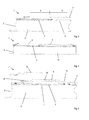
- FIG. 5 shows the embodiment according to FIG. 2 in cross section.
- the mixing chamber 11, which is surrounded by the burner frame 2, is covered on its upper side by the distributor plate 5.
- the first fiber knitted fabric 3 is located on the distributor plate 5.
- the monitoring area 4 is at a distance of about 1mm to 3mm above the distributor plate 5, the metal sheet 9.
- the metal sheet 9 at its the burner frame 2 facing narrow side 12th freely slidably held on the burner frame 2 (floating bearing).
- the metal sheet 9 is firmly connected to the distributor plate 5, so that a fixed bearing is formed. In the longitudinal direction, the metal sheet 9 can therefore expand freely, so that no thermal stresses occur.
- a fuel-air mixture passes from the mixing chamber 11 through the outlet openings 7 of the distributor plate 5 and flows through the first fiber fabric 3 in the main region 6, so that 3 flames can be formed on a side facing away from the distributor plate 5 side of the first fiber knitted fabric.
- the fuel-air mixture flows through the openings 10 of the metal sheet 9, so that 9 forms a defined flame on a side facing away from the distributor plate 5 side of the metal sheet.
- the distributor plate 5 is thus protected in the main region 6 by the first fiber knitted fabric 3 and in the monitoring region 4 by the metal sheet 9 against thermal stress from the flames. Accordingly, the distributor plate 5 may be made relatively thin and, for example, have a thickness of 0.6 mm.
- the outlet openings 7 are arranged at a smaller distance from one another than in the main area 6. As a result, the volume flow per unit area in the monitoring area 4 is greater than in the main area 6.
- a monitoring electrode 14 is arranged, with which the conductivity of the burning ionized fuel-air mixture is detected. From this it is possible to determine the air ratio or the residual oxygen content and thus achieve an air ratio control.
- the monitoring electrode 14 is therefore also referred to as ionization electrode.
- FIG. 6a a further embodiment of the surface burner 1 is shown in cross section, which is largely according to the embodiments FIG. 3 and FIG. 5 equivalent.
- the distributor plate 5 in the monitoring area 4 has an interruption (recess) 15.
- the fuel-air mixture thus passes from the mixing chamber 11 through the interruption 15 directly to the metal sheet 9 and can escape through the openings 10.
- a flow resistance in the monitoring area 4 is very small and, in particular, significantly smaller than in the main area 6. This results, for example, in twice as large a flow and thus a lifting flame in the monitoring area 4, whereby a thermal load of the metal sheet 9 is kept low.
- a strong flame is ensured even if only a small power from the surface burner 1 is required and, accordingly, relatively little fuel-air mixture is supplied.
- Fig. 6b is the surface burner 1 shown in the operating state in which flames 22 are ignited at the burner surface by outflowing fuel-air mixture.
- a much more controlled, defined flame is formed than in the main area 6.
- the surface burner corresponds to 1 in FIGS. 6a and 6b the embodiment according to FIG. 5 ,
- FIG. 7 a further embodiment of the surface burner 1 is shown in cross section, wherein the entire burner surface, so both the main area 6 and the monitoring area 4 is covered by the first fiber knit 3. So that in the monitoring area 4 no influence on the fuel-air mixture, 4 nozzles 16 are provided in the monitoring area, which penetrate the first fiber knit 3. For this purpose, stitches of the first fiber knitted fabric 3 are widened through the nozzles 16, whereby the first fiber knit fabric 3 is held on the nozzles 16 in a force-locking and / or form-fitting manner. The nozzles 16 are riveted into the distributor plate 5 and provide a fluid-conducting connection to the mixing chamber 11.
- FIG. 8 shows an embodiment of the surface burner 1, wherein the nozzles 16 not as in the embodiment of FIG. 7 are riveted, but have been integrally formed by deep drawing from the distributor plate 5. This results in very favorable flow conditions.
- the first fiber knitted fabric 3 in the monitoring area 4 is welded to the distributor plate 5, with individual spot welds are sufficient.
- FIG. 9 shows a sectional view of a preferred embodiment of the nozzle 16.
- the nozzle 16 has a lying on the longitudinal axis 17 outlet channel 18 and two lateral outlet channels 19, 20. This results in a very uniform distribution of the fuel-air mixture above the monitoring area 4 and thus a strong flame with light and reproducible from burner to burner ionization measurement.
- either no burner medium is placed in the monitoring area 4 at all, so that the flames are formed directly above the distributor plate, or burner media are used which provide lower flow resistance and / or more defined flow conditions than the first fiber knit 3.
- a lighter second fiber knitted fabric having a lower flow resistance, or a metal sheet with openings which is not subject to aging such as the fiber knit and can be manufactured and assembled with high repeatability.
- the distributor plate 5 is provided in the region of the monitoring area with a larger number of outlet openings. It is also conceivable to interrupt the distributor plate in the region of the monitored area, ie to cut it out, for example.
- the flame image in the monitoring area can be generated in a very defined manner.
- an uncooled surface of the distributor plate is kept very low in the monitoring area, so that a good heat dissipation can take place. It is thus obtained an exact definition of the outflow of the fuel-air mixture and thus generates a defined flame, which does not change over a longer period.
Landscapes
- Engineering & Computer Science (AREA)
- Chemical & Material Sciences (AREA)
- Combustion & Propulsion (AREA)
- Mechanical Engineering (AREA)
- General Engineering & Computer Science (AREA)
- Control Of Combustion (AREA)
- Gas Burners (AREA)
Applications Claiming Priority (1)
| Application Number | Priority Date | Filing Date | Title |
|---|---|---|---|
| DE102012014009.6A DE102012014009A1 (de) | 2012-07-17 | 2012-07-17 | Flächenbrenner und Verfahren zur Überwachung einer Flammenbildung bei einem Flächenbrenner |
Publications (3)
| Publication Number | Publication Date |
|---|---|
| EP2687781A2 true EP2687781A2 (fr) | 2014-01-22 |
| EP2687781A3 EP2687781A3 (fr) | 2017-12-13 |
| EP2687781B1 EP2687781B1 (fr) | 2020-09-09 |
Family
ID=48875503
Family Applications (1)
| Application Number | Title | Priority Date | Filing Date |
|---|---|---|---|
| EP13176109.0A Active EP2687781B1 (fr) | 2012-07-17 | 2013-07-11 | Brûleur à platine et procédé de surveillance d'une formation de flammes pour une brûleur à platine |
Country Status (4)
| Country | Link |
|---|---|
| EP (1) | EP2687781B1 (fr) |
| CN (1) | CN103574605B (fr) |
| DE (1) | DE102012014009A1 (fr) |
| ES (1) | ES2835023T3 (fr) |
Cited By (4)
| Publication number | Priority date | Publication date | Assignee | Title |
|---|---|---|---|---|
| WO2016096598A1 (fr) * | 2014-12-16 | 2016-06-23 | Robert Bosch Gmbh | Système de brûleur et procédé permettant d'optimiser un système de brûleur |
| DE102016108041A1 (de) * | 2016-04-29 | 2017-11-02 | Webasto SE | Verdampferkörper |
| EP3441668A1 (fr) * | 2017-08-08 | 2019-02-13 | Robert Bosch GmbH | Recouvrement de brûleur, procédé de fabrication d'un recouvrement de brûleur ainsi que brûleur de surface |
| EP3910237A3 (fr) * | 2020-05-12 | 2022-02-23 | Vaillant GmbH | Agencement de brûleur et tôle de distribution |
Families Citing this family (7)
| Publication number | Priority date | Publication date | Assignee | Title |
|---|---|---|---|---|
| EP2870409B1 (fr) * | 2012-07-03 | 2020-03-25 | Dreizler, Ulrich | Brûleur à système de combustion superficielle |
| DE102015014246A1 (de) * | 2015-11-05 | 2017-05-11 | Alexander Buchner | Flammenprojektor |
| DE202016105039U1 (de) * | 2016-09-12 | 2017-09-14 | Viessmann Werke Gmbh & Co Kg | Gasbrenner |
| DE102017204013A1 (de) | 2017-03-10 | 2018-09-13 | Robert Bosch Gmbh | Verfahren zur Herstellung eines Flächenbrenners sowie ein Flächenbrenner |
| JP6853075B2 (ja) * | 2017-03-13 | 2021-03-31 | リンナイ株式会社 | 全一次燃焼式バーナ |
| DE102019216769A1 (de) * | 2019-10-30 | 2021-05-06 | Robert Bosch Gmbh | Voll- oder teilvormischender Brenner für einen gasförmigen Brennstoff mit einer sehr hohen Flammengeschwindigkeit |
| CN116906901B (zh) * | 2023-08-23 | 2026-03-20 | 哈尔滨工业大学 | 平面火焰燃烧器及可调节旋流强度的非预混式旋流燃烧器 |
Citations (2)
| Publication number | Priority date | Publication date | Assignee | Title |
|---|---|---|---|---|
| EP0339499A2 (fr) | 1988-04-28 | 1989-11-02 | Joh. Vaillant GmbH u. Co. | Dispositif de surveillance du fonctionnement de la plaque de brûleur d'un brûleur à panneaux |
| DE102005056499A1 (de) | 2005-11-28 | 2007-05-31 | Schott Ag | Gasbrenner |
Family Cites Families (12)
| Publication number | Priority date | Publication date | Assignee | Title |
|---|---|---|---|---|
| JPS5616018A (en) * | 1979-07-20 | 1981-02-16 | Osaka Gas Co Ltd | Surface combustion |
| ATE174681T1 (de) * | 1992-03-03 | 1999-01-15 | Bekaert Sa Nv | Poröse metallfiber-platte |
| GB2302401B (en) * | 1995-06-15 | 1999-08-04 | British Gas Plc | Fuel fired burners |
| DE19605649A1 (de) * | 1996-02-15 | 1997-08-21 | Oranier Heiz & Kochtechnik | Gasbrenner für Herde |
| DE19718898C1 (de) * | 1997-05-03 | 1998-10-22 | Bosch Gmbh Robert | Gasbrenner mit einem porösen Brennkörper |
| DE19943615A1 (de) * | 1999-09-11 | 2001-03-15 | Bosch Gmbh Robert | Brenner, insbesondere für Heizungsanlagen |
| CN2434539Y (zh) * | 2000-07-11 | 2001-06-13 | 上海天行机电设备成套公司 | 全预混式金属纤维燃烧器 |
| CN2437975Y (zh) * | 2000-07-14 | 2001-07-04 | 广州市红日燃具公司 | 一种改进型家用燃气灶具燃烧器 |
| DE10038095C2 (de) * | 2000-08-04 | 2002-06-13 | Bosch Gmbh Robert | Anordnung zur Flammenüberwachung von Poren- und Gestrickbrennern |
| JP2002267115A (ja) * | 2001-03-06 | 2002-09-18 | Nhk Spring Co Ltd | 表面燃焼バーナ |
| JP2003343813A (ja) * | 2002-05-30 | 2003-12-03 | Matsushita Electric Ind Co Ltd | バーナおよびこれを用いた調理器 |
| IT1399919B1 (it) * | 2010-05-05 | 2013-05-09 | Worgas Bruciatori Srl | Bruciatore a gas per caldaia |
-
2012
- 2012-07-17 DE DE102012014009.6A patent/DE102012014009A1/de not_active Ceased
-
2013
- 2013-07-11 ES ES13176109T patent/ES2835023T3/es active Active
- 2013-07-11 EP EP13176109.0A patent/EP2687781B1/fr active Active
- 2013-07-15 CN CN201310472526.5A patent/CN103574605B/zh active Active
Patent Citations (2)
| Publication number | Priority date | Publication date | Assignee | Title |
|---|---|---|---|---|
| EP0339499A2 (fr) | 1988-04-28 | 1989-11-02 | Joh. Vaillant GmbH u. Co. | Dispositif de surveillance du fonctionnement de la plaque de brûleur d'un brûleur à panneaux |
| DE102005056499A1 (de) | 2005-11-28 | 2007-05-31 | Schott Ag | Gasbrenner |
Cited By (5)
| Publication number | Priority date | Publication date | Assignee | Title |
|---|---|---|---|---|
| WO2016096598A1 (fr) * | 2014-12-16 | 2016-06-23 | Robert Bosch Gmbh | Système de brûleur et procédé permettant d'optimiser un système de brûleur |
| DE102016108041A1 (de) * | 2016-04-29 | 2017-11-02 | Webasto SE | Verdampferkörper |
| DE102016108041B4 (de) | 2016-04-29 | 2019-12-05 | Webasto SE | Verdampferkörper |
| EP3441668A1 (fr) * | 2017-08-08 | 2019-02-13 | Robert Bosch GmbH | Recouvrement de brûleur, procédé de fabrication d'un recouvrement de brûleur ainsi que brûleur de surface |
| EP3910237A3 (fr) * | 2020-05-12 | 2022-02-23 | Vaillant GmbH | Agencement de brûleur et tôle de distribution |
Also Published As
| Publication number | Publication date |
|---|---|
| EP2687781B1 (fr) | 2020-09-09 |
| ES2835023T3 (es) | 2021-06-21 |
| DE102012014009A1 (de) | 2014-01-23 |
| CN103574605A (zh) | 2014-02-12 |
| CN103574605B (zh) | 2019-03-08 |
| EP2687781A3 (fr) | 2017-12-13 |
Similar Documents
| Publication | Publication Date | Title |
|---|---|---|
| EP2687781B1 (fr) | Brûleur à platine et procédé de surveillance d'une formation de flammes pour une brûleur à platine | |
| EP2467642B1 (fr) | Brûleur radiant | |
| EP4176205B1 (fr) | Dispositif brûleur à gaz et procédé de fonctionnement d'un dispositif brûleur à gaz | |
| EP2641022B1 (fr) | Procédé de combustion et membrane avec base de flammes froide | |
| EP2090826B1 (fr) | Tête de brûleur à gaz | |
| DE69227094T2 (de) | Brenner mit Oberflächenverbrennung | |
| EP3293455B1 (fr) | Brûleur à gaz | |
| DE102019216769A1 (de) | Voll- oder teilvormischender Brenner für einen gasförmigen Brennstoff mit einer sehr hohen Flammengeschwindigkeit | |
| EP4141321A1 (fr) | Dispositif de brûleur à gaz avec dispositif arrête-flamme | |
| DE69611124T2 (de) | Brennstoffbefeuerter Brenner | |
| DE19847042B4 (de) | Hochporöse Brennermatte für Gas- und/oder Ölbrenner | |
| DE69127997T2 (de) | Brenner mit oberflächenverbrennung | |
| EP4246043A1 (fr) | Ensemble brûleur à gaz, appareil de chauffage à gaz et utilisation | |
| DE202019103989U1 (de) | Gasbrenner | |
| DE19724806A1 (de) | Vollvormischender atmosphärischer Strahlungsbrenner | |
| DE69127781T2 (de) | Brenner mit oberflächenverbrennung | |
| EP3234463B1 (fr) | Système de brûleur | |
| EP3910237B1 (fr) | Agencement de brûleur et tôle de distribution | |
| DE19605649A1 (de) | Gasbrenner für Herde | |
| EP3372895B1 (fr) | Procédé de fabrication d'un brûleur en nappe ainsi que brûleur en nappe | |
| EP3988841A1 (fr) | Procédé et dispositif pour empêcher le retour de flamme dans un dispositif brûleur pour un mélange préalablement mélangé de combustible et d'air | |
| EP3910238A1 (fr) | Cône pilote | |
| DE102024118585A1 (de) | Brennerkörper, Gasbrenner, Heizgerät sowie Verwendung und Verfahren zur Verbrennung von Wasserstoff-Brenngas | |
| DE29511493U1 (de) | Gasbrenner | |
| EP4295082A1 (fr) | Procédé pour faire fonctionner un brûleur à gaz |
Legal Events
| Date | Code | Title | Description |
|---|---|---|---|
| PUAI | Public reference made under article 153(3) epc to a published international application that has entered the european phase |
Free format text: ORIGINAL CODE: 0009012 |
|
| AK | Designated contracting states |
Kind code of ref document: A2 Designated state(s): AL AT BE BG CH CY CZ DE DK EE ES FI FR GB GR HR HU IE IS IT LI LT LU LV MC MK MT NL NO PL PT RO RS SE SI SK SM TR |
|
| AX | Request for extension of the european patent |
Extension state: BA ME |
|
| PUAL | Search report despatched |
Free format text: ORIGINAL CODE: 0009013 |
|
| AK | Designated contracting states |
Kind code of ref document: A3 Designated state(s): AL AT BE BG CH CY CZ DE DK EE ES FI FR GB GR HR HU IE IS IT LI LT LU LV MC MK MT NL NO PL PT RO RS SE SI SK SM TR |
|
| AX | Request for extension of the european patent |
Extension state: BA ME |
|
| RIC1 | Information provided on ipc code assigned before grant |
Ipc: F23D 14/26 20060101ALI20171106BHEP Ipc: F23D 14/02 20060101AFI20171106BHEP Ipc: F23D 14/72 20060101ALI20171106BHEP |
|
| STAA | Information on the status of an ep patent application or granted ep patent |
Free format text: STATUS: REQUEST FOR EXAMINATION WAS MADE |
|
| 17P | Request for examination filed |
Effective date: 20180613 |
|
| RBV | Designated contracting states (corrected) |
Designated state(s): AL AT BE BG CH CY CZ DE DK EE ES FI FR GB GR HR HU IE IS IT LI LT LU LV MC MK MT NL NO PL PT RO RS SE SI SK SM TR |
|
| STAA | Information on the status of an ep patent application or granted ep patent |
Free format text: STATUS: EXAMINATION IS IN PROGRESS |
|
| 17Q | First examination report despatched |
Effective date: 20190205 |
|
| GRAP | Despatch of communication of intention to grant a patent |
Free format text: ORIGINAL CODE: EPIDOSNIGR1 |
|
| STAA | Information on the status of an ep patent application or granted ep patent |
Free format text: STATUS: GRANT OF PATENT IS INTENDED |
|
| INTG | Intention to grant announced |
Effective date: 20200320 |
|
| RAP1 | Party data changed (applicant data changed or rights of an application transferred) |
Owner name: ROBERT BOSCH GMBH |
|
| GRAS | Grant fee paid |
Free format text: ORIGINAL CODE: EPIDOSNIGR3 |
|
| GRAA | (expected) grant |
Free format text: ORIGINAL CODE: 0009210 |
|
| STAA | Information on the status of an ep patent application or granted ep patent |
Free format text: STATUS: THE PATENT HAS BEEN GRANTED |
|
| AK | Designated contracting states |
Kind code of ref document: B1 Designated state(s): AL AT BE BG CH CY CZ DE DK EE ES FI FR GB GR HR HU IE IS IT LI LT LU LV MC MK MT NL NO PL PT RO RS SE SI SK SM TR |
|
| REG | Reference to a national code |
Ref country code: GB Ref legal event code: FG4D Free format text: NOT ENGLISH |
|
| REG | Reference to a national code |
Ref country code: AT Ref legal event code: REF Ref document number: 1312028 Country of ref document: AT Kind code of ref document: T Effective date: 20200915 Ref country code: CH Ref legal event code: EP |
|
| REG | Reference to a national code |
Ref country code: DE Ref legal event code: R096 Ref document number: 502013015105 Country of ref document: DE |
|
| REG | Reference to a national code |
Ref country code: IE Ref legal event code: FG4D Free format text: LANGUAGE OF EP DOCUMENT: GERMAN |
|
| REG | Reference to a national code |
Ref country code: LT Ref legal event code: MG4D |
|
| PG25 | Lapsed in a contracting state [announced via postgrant information from national office to epo] |
Ref country code: SE Free format text: LAPSE BECAUSE OF FAILURE TO SUBMIT A TRANSLATION OF THE DESCRIPTION OR TO PAY THE FEE WITHIN THE PRESCRIBED TIME-LIMIT Effective date: 20200909 Ref country code: HR Free format text: LAPSE BECAUSE OF FAILURE TO SUBMIT A TRANSLATION OF THE DESCRIPTION OR TO PAY THE FEE WITHIN THE PRESCRIBED TIME-LIMIT Effective date: 20200909 Ref country code: BG Free format text: LAPSE BECAUSE OF FAILURE TO SUBMIT A TRANSLATION OF THE DESCRIPTION OR TO PAY THE FEE WITHIN THE PRESCRIBED TIME-LIMIT Effective date: 20201209 Ref country code: NO Free format text: LAPSE BECAUSE OF FAILURE TO SUBMIT A TRANSLATION OF THE DESCRIPTION OR TO PAY THE FEE WITHIN THE PRESCRIBED TIME-LIMIT Effective date: 20201209 Ref country code: FI Free format text: LAPSE BECAUSE OF FAILURE TO SUBMIT A TRANSLATION OF THE DESCRIPTION OR TO PAY THE FEE WITHIN THE PRESCRIBED TIME-LIMIT Effective date: 20200909 Ref country code: GR Free format text: LAPSE BECAUSE OF FAILURE TO SUBMIT A TRANSLATION OF THE DESCRIPTION OR TO PAY THE FEE WITHIN THE PRESCRIBED TIME-LIMIT Effective date: 20201210 Ref country code: LT Free format text: LAPSE BECAUSE OF FAILURE TO SUBMIT A TRANSLATION OF THE DESCRIPTION OR TO PAY THE FEE WITHIN THE PRESCRIBED TIME-LIMIT Effective date: 20200909 |
|
| REG | Reference to a national code |
Ref country code: NL Ref legal event code: MP Effective date: 20200909 |
|
| PG25 | Lapsed in a contracting state [announced via postgrant information from national office to epo] |
Ref country code: LV Free format text: LAPSE BECAUSE OF FAILURE TO SUBMIT A TRANSLATION OF THE DESCRIPTION OR TO PAY THE FEE WITHIN THE PRESCRIBED TIME-LIMIT Effective date: 20200909 Ref country code: PL Free format text: LAPSE BECAUSE OF FAILURE TO SUBMIT A TRANSLATION OF THE DESCRIPTION OR TO PAY THE FEE WITHIN THE PRESCRIBED TIME-LIMIT Effective date: 20200909 Ref country code: RS Free format text: LAPSE BECAUSE OF FAILURE TO SUBMIT A TRANSLATION OF THE DESCRIPTION OR TO PAY THE FEE WITHIN THE PRESCRIBED TIME-LIMIT Effective date: 20200909 |
|
| PG25 | Lapsed in a contracting state [announced via postgrant information from national office to epo] |
Ref country code: EE Free format text: LAPSE BECAUSE OF FAILURE TO SUBMIT A TRANSLATION OF THE DESCRIPTION OR TO PAY THE FEE WITHIN THE PRESCRIBED TIME-LIMIT Effective date: 20200909 Ref country code: CZ Free format text: LAPSE BECAUSE OF FAILURE TO SUBMIT A TRANSLATION OF THE DESCRIPTION OR TO PAY THE FEE WITHIN THE PRESCRIBED TIME-LIMIT Effective date: 20200909 Ref country code: RO Free format text: LAPSE BECAUSE OF FAILURE TO SUBMIT A TRANSLATION OF THE DESCRIPTION OR TO PAY THE FEE WITHIN THE PRESCRIBED TIME-LIMIT Effective date: 20200909 Ref country code: SM Free format text: LAPSE BECAUSE OF FAILURE TO SUBMIT A TRANSLATION OF THE DESCRIPTION OR TO PAY THE FEE WITHIN THE PRESCRIBED TIME-LIMIT Effective date: 20200909 Ref country code: PT Free format text: LAPSE BECAUSE OF FAILURE TO SUBMIT A TRANSLATION OF THE DESCRIPTION OR TO PAY THE FEE WITHIN THE PRESCRIBED TIME-LIMIT Effective date: 20210111 Ref country code: NL Free format text: LAPSE BECAUSE OF FAILURE TO SUBMIT A TRANSLATION OF THE DESCRIPTION OR TO PAY THE FEE WITHIN THE PRESCRIBED TIME-LIMIT Effective date: 20200909 |
|
| PG25 | Lapsed in a contracting state [announced via postgrant information from national office to epo] |
Ref country code: AL Free format text: LAPSE BECAUSE OF FAILURE TO SUBMIT A TRANSLATION OF THE DESCRIPTION OR TO PAY THE FEE WITHIN THE PRESCRIBED TIME-LIMIT Effective date: 20200909 Ref country code: IS Free format text: LAPSE BECAUSE OF FAILURE TO SUBMIT A TRANSLATION OF THE DESCRIPTION OR TO PAY THE FEE WITHIN THE PRESCRIBED TIME-LIMIT Effective date: 20210109 |
|
| REG | Reference to a national code |
Ref country code: DE Ref legal event code: R097 Ref document number: 502013015105 Country of ref document: DE |
|
| REG | Reference to a national code |
Ref country code: ES Ref legal event code: FG2A Ref document number: 2835023 Country of ref document: ES Kind code of ref document: T3 Effective date: 20210621 |
|
| PG25 | Lapsed in a contracting state [announced via postgrant information from national office to epo] |
Ref country code: SK Free format text: LAPSE BECAUSE OF FAILURE TO SUBMIT A TRANSLATION OF THE DESCRIPTION OR TO PAY THE FEE WITHIN THE PRESCRIBED TIME-LIMIT Effective date: 20200909 |
|
| PLBE | No opposition filed within time limit |
Free format text: ORIGINAL CODE: 0009261 |
|
| STAA | Information on the status of an ep patent application or granted ep patent |
Free format text: STATUS: NO OPPOSITION FILED WITHIN TIME LIMIT |
|
| 26N | No opposition filed |
Effective date: 20210610 |
|
| PG25 | Lapsed in a contracting state [announced via postgrant information from national office to epo] |
Ref country code: DK Free format text: LAPSE BECAUSE OF FAILURE TO SUBMIT A TRANSLATION OF THE DESCRIPTION OR TO PAY THE FEE WITHIN THE PRESCRIBED TIME-LIMIT Effective date: 20200909 Ref country code: SI Free format text: LAPSE BECAUSE OF FAILURE TO SUBMIT A TRANSLATION OF THE DESCRIPTION OR TO PAY THE FEE WITHIN THE PRESCRIBED TIME-LIMIT Effective date: 20200909 |
|
| PG25 | Lapsed in a contracting state [announced via postgrant information from national office to epo] |
Ref country code: MC Free format text: LAPSE BECAUSE OF FAILURE TO SUBMIT A TRANSLATION OF THE DESCRIPTION OR TO PAY THE FEE WITHIN THE PRESCRIBED TIME-LIMIT Effective date: 20200909 |
|
| REG | Reference to a national code |
Ref country code: BE Ref legal event code: MM Effective date: 20210731 |
|
| PG25 | Lapsed in a contracting state [announced via postgrant information from national office to epo] |
Ref country code: LU Free format text: LAPSE BECAUSE OF NON-PAYMENT OF DUE FEES Effective date: 20210711 |
|
| PG25 | Lapsed in a contracting state [announced via postgrant information from national office to epo] |
Ref country code: IE Free format text: LAPSE BECAUSE OF NON-PAYMENT OF DUE FEES Effective date: 20210711 Ref country code: BE Free format text: LAPSE BECAUSE OF NON-PAYMENT OF DUE FEES Effective date: 20210731 |
|
| PG25 | Lapsed in a contracting state [announced via postgrant information from national office to epo] |
Ref country code: HU Free format text: LAPSE BECAUSE OF FAILURE TO SUBMIT A TRANSLATION OF THE DESCRIPTION OR TO PAY THE FEE WITHIN THE PRESCRIBED TIME-LIMIT; INVALID AB INITIO Effective date: 20130711 |
|
| PG25 | Lapsed in a contracting state [announced via postgrant information from national office to epo] |
Ref country code: CY Free format text: LAPSE BECAUSE OF FAILURE TO SUBMIT A TRANSLATION OF THE DESCRIPTION OR TO PAY THE FEE WITHIN THE PRESCRIBED TIME-LIMIT Effective date: 20200909 |
|
| PG25 | Lapsed in a contracting state [announced via postgrant information from national office to epo] |
Ref country code: MK Free format text: LAPSE BECAUSE OF FAILURE TO SUBMIT A TRANSLATION OF THE DESCRIPTION OR TO PAY THE FEE WITHIN THE PRESCRIBED TIME-LIMIT Effective date: 20200909 |
|
| PG25 | Lapsed in a contracting state [announced via postgrant information from national office to epo] |
Ref country code: TR Free format text: LAPSE BECAUSE OF FAILURE TO SUBMIT A TRANSLATION OF THE DESCRIPTION OR TO PAY THE FEE WITHIN THE PRESCRIBED TIME-LIMIT Effective date: 20200909 |
|
| PG25 | Lapsed in a contracting state [announced via postgrant information from national office to epo] |
Ref country code: MT Free format text: LAPSE BECAUSE OF FAILURE TO SUBMIT A TRANSLATION OF THE DESCRIPTION OR TO PAY THE FEE WITHIN THE PRESCRIBED TIME-LIMIT Effective date: 20200909 |
|
| PGFP | Annual fee paid to national office [announced via postgrant information from national office to epo] |
Ref country code: ES Payment date: 20250819 Year of fee payment: 13 |
|
| PGFP | Annual fee paid to national office [announced via postgrant information from national office to epo] |
Ref country code: DE Payment date: 20250924 Year of fee payment: 13 |
|
| PGFP | Annual fee paid to national office [announced via postgrant information from national office to epo] |
Ref country code: IT Payment date: 20250731 Year of fee payment: 13 |
|
| PGFP | Annual fee paid to national office [announced via postgrant information from national office to epo] |
Ref country code: GB Payment date: 20250724 Year of fee payment: 13 |
|
| PGFP | Annual fee paid to national office [announced via postgrant information from national office to epo] |
Ref country code: FR Payment date: 20250723 Year of fee payment: 13 Ref country code: AT Payment date: 20250721 Year of fee payment: 13 |
|
| PGFP | Annual fee paid to national office [announced via postgrant information from national office to epo] |
Ref country code: CH Payment date: 20250801 Year of fee payment: 13 |