EP3441981A1 - Module d'optique en rayons x comprenant un système de transfert pour trois trajets de rayonnement et rotule et diffractomètre correspondant - Google Patents
Module d'optique en rayons x comprenant un système de transfert pour trois trajets de rayonnement et rotule et diffractomètre correspondant Download PDFInfo
- Publication number
- EP3441981A1 EP3441981A1 EP18194157.6A EP18194157A EP3441981A1 EP 3441981 A1 EP3441981 A1 EP 3441981A1 EP 18194157 A EP18194157 A EP 18194157A EP 3441981 A1 EP3441981 A1 EP 3441981A1
- Authority
- EP
- European Patent Office
- Prior art keywords
- ray
- axis
- carriage
- monochromator
- adjusting unit
- Prior art date
- Legal status (The legal status is an assumption and is not a legal conclusion. Google has not performed a legal analysis and makes no representation as to the accuracy of the status listed.)
- Granted
Links
Images


Classifications
-
- G—PHYSICS
- G01—MEASURING; TESTING
- G01N—INVESTIGATING OR ANALYSING MATERIALS BY DETERMINING THEIR CHEMICAL OR PHYSICAL PROPERTIES
- G01N23/00—Investigating or analysing materials by the use of wave or particle radiation, e.g. X-rays or neutrons, not covered by groups G01N3/00 – G01N17/00, G01N21/00 or G01N22/00
- G01N23/20—Investigating or analysing materials by the use of wave or particle radiation, e.g. X-rays or neutrons, not covered by groups G01N3/00 – G01N17/00, G01N21/00 or G01N22/00 by using diffraction of the radiation by the materials, e.g. for investigating crystal structure; by using scattering of the radiation by the materials, e.g. for investigating non-crystalline materials; by using reflection of the radiation by the materials
- G01N23/207—Diffractometry using detectors, e.g. using a probe in a central position and one or more displaceable detectors in circumferential positions
-
- G—PHYSICS
- G21—NUCLEAR PHYSICS; NUCLEAR ENGINEERING
- G21K—HANDLING OF PARTICLES OR IONISING RADIATION NOT OTHERWISE PROVIDED FOR; IRRADIATION DEVICES; GAMMA RAY OR X-RAY MICROSCOPES
- G21K1/00—Arrangements for handling particles or ionising radiation, e.g. focusing or moderating
- G21K1/06—Arrangements for handling particles or ionising radiation, e.g. focusing or moderating using diffraction, refraction or reflection, e.g. monochromators
-
- G—PHYSICS
- G01—MEASURING; TESTING
- G01N—INVESTIGATING OR ANALYSING MATERIALS BY DETERMINING THEIR CHEMICAL OR PHYSICAL PROPERTIES
- G01N2223/00—Investigating materials by wave or particle radiation
- G01N2223/30—Accessories, mechanical or electrical features
- G01N2223/315—Accessories, mechanical or electrical features monochromators
-
- G—PHYSICS
- G21—NUCLEAR PHYSICS; NUCLEAR ENGINEERING
- G21K—HANDLING OF PARTICLES OR IONISING RADIATION NOT OTHERWISE PROVIDED FOR; IRRADIATION DEVICES; GAMMA RAY OR X-RAY MICROSCOPES
- G21K2201/00—Arrangements for handling radiation or particles
- G21K2201/06—Arrangements for handling radiation or particles using diffractive, refractive or reflecting elements
- G21K2201/061—Arrangements for handling radiation or particles using diffractive, refractive or reflecting elements characterised by a multilayer structure
-
- G—PHYSICS
- G21—NUCLEAR PHYSICS; NUCLEAR ENGINEERING
- G21K—HANDLING OF PARTICLES OR IONISING RADIATION NOT OTHERWISE PROVIDED FOR; IRRADIATION DEVICES; GAMMA RAY OR X-RAY MICROSCOPES
- G21K2201/00—Arrangements for handling radiation or particles
- G21K2201/06—Arrangements for handling radiation or particles using diffractive, refractive or reflecting elements
- G21K2201/062—Arrangements for handling radiation or particles using diffractive, refractive or reflecting elements the element being a crystal
Definitions
- the invention relates to an X-ray optics assembly for an X-ray diffractometer, comprising a multilayer mirror, in particular Goebel mirror, and a switching system, with which beam paths for an X-ray beam can be selected, wherein the X-ray optical assembly further comprises a monochromator, in particular a channel-cut crystal, and wherein with the switching system three beam paths for the X-ray beam are selectable, wherein a first beam path leads past the multilayer mirror in a first position of the switching system and leads past the monochromator, wherein a second beam path in a second position of the switching system contains the multilayer mirror and leads past the monochromator, and wherein a third beam path in a third position of the switching system contains the multilayer mirror and contains the monochromator.
- Such an X-ray optics assembly is for example from the EP 1 912 061 A1 known.
- X-ray diffraction is a powerful method of instrumental analysis that allows the characterization of especially crystalline materials.
- different measuring geometries are used.
- the Bragg-Brentano geometry in which an X-ray beam is focused on the detector (or detector aperture) after reflection from the sample, is often used in powder diffractometry.
- parallel beam geometry an X-ray beam is directed parallel to the sample, for example for texture measurements.
- Different X-ray optical elements are needed in the beam path for the different measuring geometries.
- the DE 10 2009 047 672 A1 discloses an X-ray optical structure in which a change between a reflection geometry with an X-ray mirror in the primary beam side beam path and a transmission geometry with two X-ray mirrors in the primary beam side beam path is set up by means of a displaceable or rotatable diaphragm system. Conversion and adjustment work is minimized or superfluous.
- an X-ray diffractometer for measurements in a focusing geometry without reflection on a multilayer mirror and in parallel beam geometry with reflection at the multilayer mirror become, with a rotatable, slotted disc behind the multi-layer mirror one of the beam paths can be selected. Furthermore, a divergence gap is provided, which can be moved between the beam paths.
- the known X-ray diffractometers permit a change between two beam paths, such as a Bragg-Brentano geometry and a parallel beam geometry. This is sufficient in many analytical tasks; however, in some cases, high-resolution X-ray diffraction information is needed that is inaccessible with the known switchable X-ray optics.
- the US 6,359,964 B1 describes an apparatus for X-ray analysis, which has a parabolic multilayer mirror for parallelizing X-rays and a device for monochromating the parallelized radiation, in particular with a two-crystal monochromator.
- the multilayer mirror can be rotated through 180 °, whereby the X-ray beam is directed to the object to be examined either via the multilayer mirror and the monochromator, or alternatively directly from the multilayer mirror. With the monochromatized X-ray, high-resolution X-ray diffraction measurements are possible.
- An X-ray optical system has become known in which a beam path with or without a multilayer mirror arranged in front of the disk can be selected with a slotted, rotatable disk.
- a channel-cut crystal or a polycapillary can be taken into the beam path.
- the US 2004/0042584 A1 describes a goniometer arrangement for X-ray diffraction, in which a spherical sector is mounted in a ball bearing.
- the invention has for its object to provide an X-ray optics assembly or an X-ray diffractometer available, which can be used in a simple way more universal for different measurement geometries, and allows easy and precise adjustment of the monochromator.
- an X-ray optic assembly of the type mentioned which is characterized that the monochromator is attached to an adjusting unit which is mounted with a joint rotatable in two degrees of freedom, that the rotatable joint is designed as a ball joint, that a guide arrangement is provided with two opposite guide sections, between which the adjusting unit is guided, so that the adjusting unit parallel to a guide plane which is parallel to the guide sections, about a first axis (y), through the center of the ball joint and runs perpendicular to the guide plane, is pivotable, in that the adjusting unit is further rotatable about a second axis (x) passing through the center of the ball joint and perpendicular to the first axis (y), and in that the adjusting unit bears against the guide sections with respect to the direction of the second axis (x) at a distance from the center of the ball joint, such that pivoting of the adjusting unit about a third axis (z) passing through the center of the ball joint and perpendicular to
- the X-ray optical assembly With the X-ray optical assembly according to the invention, it is possible to switch between three beam paths in order to be able to process a respective analytical task with an adapted beam geometry or adapted X-ray optics.
- the outgoing X-ray beam is directed to a common sample position.
- the remaining beam paths are blocked (shadowed).
- an X-ray beam formed by means of the multilayer mirror can be used, for example in parallel beam geometry for stress and texture measurements, or in grazing incidence for the targeted characterization of near-surface sample material.
- an X-ray beam shaped and monochromatized by means of the multilayer mirror can be used for high-resolution X-ray diffraction measurements, for example for defect analysis in near perfect crystals such as semiconductor wafers.
- the X-ray optics assembly is typically assembled into a single X-ray optics device (module) that can be installed as a whole in an X-ray diffractometer.
- the switchover is typically motorized and automatic, but can also be set up manually.
- the monochromator is mounted on an adjusting unit, which is mounted with a rotatable joint in two degrees of freedom.
- the monochromator (relative to the multilayer mirror or the x-ray beam emanating from it) can be adjusted with respect to its rotational position via the rotatable joint.
- the hinge or axes of rotation are preferably arranged close to the monochromator or to the x-ray beam, e.g. at a distance of 2 cm or less.
- the hinge is mounted on a traveling carriage of the X-ray optics assembly, which carries the monochromator and a switchable aperture system.
- the adjusting unit typically comprises a holding element, on which the joint is formed, and an adjusting element for adjusting the monochromator, in particular an adjusting lever extending laterally from the holding element.
- the rotatable joint is formed as a ball joint.
- Ball joints allow very precise and well-retaining settings.
- the ball joint is basically rotatable with respect to three degrees of freedom. One degree of freedom is inventively blocked by a suitable guide to facilitate the adjustment.
- the rotation of the adjustment unit is limited to two axes (x, y) to facilitate the adjustment.
- the guide sections are usually designed as guide surfaces, but may also be designed as guide edges.
- the guide portions are typically biased slightly elastically on the adjusting unit to reduce the game.
- the Guide arrangement is typically formed on the movable carriage.
- the first, second and third axes (x, y, z) are oriented perpendicular to one another.
- the carriage is movable on a main body of the X-ray optics assembly with guides between two end stops, in particular wherein the two end stops are adjustable.
- the end stops facilitate quick and accurate positioning of the switchable iris and monochromator.
- adjustable end stops With adjustable end stops, the positions of the switchable cover system and the monochromator with respect to the travel direction (VRS) of the slide can be adjusted.
- VRS travel direction
- a further development for this provides that on or in the carriage, a guide pin is guided, which is parallel to a direction of travel (VRS) of the carriage along a sliding direction (SRF) relative to the carriage movable, and that in the sliding direction (SRF) on either side of the guide pin on or in each case a contact element is formed in the carriage, which is movable parallel to the sliding direction (SRF) on or in the carriage and is supported via a respective first spring element on the carriage.
- the position of the end stop can vary, and yet reliably sufficient force is exerted on the carriage for a precise abutment with the end stop.
- After reaching the end stop by the carriage of the guide pin is still noticeably, typically about half its possible travel (maximum spring stroke) to move against the force of the first spring element on the end stop.
- a respective travel of the abutment elements relative to the carriage, starting from a central position of the guide pin, is preferably at least 3.0 mm.
- the abutment elements may be designed as locking discs whose travel is limited to the guide pin to by locking stops; Accordingly, at least temporarily, only one contact element is then applied to the guide pin when moving the guide pin from a central position. This prevents the method from being supported on one of the end stops of the first spring element of the opposite end stop.
- a drive spindle is formed, on which a base body guided spindle nut is seated, and that the guide pin is coupled to the spindle nut, in particular via a laterally projecting from the guide pin driver.
- the spindle mechanics are simple, robust and cost-effective. Due to the transmission of force via the guide pin and the first spring elements, the spindle mechanism, which in itself is less precise, is also sufficient for precise positioning of the carriage.
- the adjusting unit comprises a holding element and an adjusting element, wherein the holding element has a ball portion, a first connecting portion from the ball portion to the monochromator, and a second connecting portion from the ball portion to the adjusting element.
- the holding element is typically formed substantially straight, with approximately centrally located ball portion and opposite connecting portions ("spindle").
- This embodiment allows a favorable force entry during the adjustment and a compact design.
- the adjusting unit is formed with a ball portion, wherein the ball portion is disposed between two socket elements, in particular wherein the socket elements are formed as perforated plastic discs, and that the joint socket elements by means of one or a plurality of second spring elements, in particular disc springs, are biased towards each other.
- This design allows a simple way almost a play-free holding the adjusting unit.
- the guide assembly is rotatably formed about the second axis (x), wherein the adjusting unit with respect to the direction of the third axis (z) spaced from the center of the ball joint abuts the guide portions, so that the adjusting unit upon rotation about the second axis (x ) the guiding arrangement rotates, in particular, wherein the guide arrangement is formed with a locking sleeve.
- the position of the first axis (y) is fixed to the monochromator. This allows a particularly simple, intuitive adjustment. In addition, nonlinearities can be avoided in this design, if relevant, for large angles of rotation.
- the guide arrangement is typically rotatably mounted on the movable carriage.
- the guide arrangement is formed rotationally fixed, in that the alignment unit bears against the guide sections with circular cylinder jacket surface sections, wherein a common cylinder axis of the circular cylinder jacket surface sections runs through the center point of the ball joint so that upon rotation of the alignment unit about the second axis (x) the adjusting unit rotates in relation to the guide arrangement around the common cylinder axis, in particular, wherein the guide arrangement guides the adjusting unit in a circular cylindrical area.
- the circular cylinder jacket surface portions are formed by opposite sides of a circular cylindrical portion of the adjusting unit.
- the circular cylindrical peripheral surface sections When extended in the direction of the x-axis guide portions, the circular cylindrical peripheral surface sections can be formed axially also very short; the cylinder axis then corresponds to the axis through the common circular arc section center, perpendicular to the common circle plane.
- a first adjusting mechanism for pivoting the adjusting unit about a first axis (y) and a second adjusting mechanism for rotating the adjusting unit about a second axis (x) are provided.
- the adjusting unit has a substantially transverse to the second axis (x) extending adjusting lever on which the first and the second adjustment mechanism attack that the adjusting lever with the first adjustment mechanism in a direction approximately parallel to the second axis (x) is deflectable, and that the adjusting lever with the second adjusting mechanism in a direction approximately parallel to the first axis (y) is deflectable.
- the adjustment lever an adjustment of the monochromator is possible in a simple and precise way.
- an adjusting wheel can also be used, for example.
- the first adjusting mechanism and the second adjusting mechanism respectively press the adjusting unit with the force of a respective third spring element, in particular a tension spring, against an adjustable adjusting stop, in particular a threaded spindle or adjusting screw.
- a respective third spring element in particular a tension spring
- an adjustable adjusting stop in particular a threaded spindle or adjusting screw.
- the adjustment system further comprises a primary side carriage, on which at least the X-ray source and the X-ray optics assembly are arranged, and which are moved and / or pivoted at least between a first layer and a second layer can in particular, wherein a positional difference between the second layer and the first layer of the primary side carriage compensates for an X-ray change by the monochromator in the third beam path relative to the second beam path.
- the first layer is used for the second beam path or the second adjustment
- the second layer is used for the third beam path or the third adjustment.
- the first layer is typically used for the first beam path or the first adjustment.
- This design allows the use of a monochromator that changes the X-ray beam in the third beam path relative to the second beam path output side of the X-ray optics assembly, in particular the use of a (simple) channel-cut crystal, which also very compact designs (with a small distance between the X-ray source and Sample).
- a typical x-ray change by the monochromator is a parallel offset of the x-ray beam, which is compensated for by a similar, co-translation of x-ray source and x-ray optics assembly.
- the monochromator is designed such that the second beam path and the third beam path output side of the X-ray optics assembly relative to the X-ray optics assembly in particular, wherein the monochromator in succession comprises two Channel Cut crystals in Bartels arrangement, and that the adjustment system comprises only the switching system of the X-ray optics assembly.
- This type of construction is particularly easy to change since no primary side slide is required.
- the monochromator must be made very precise for this embodiment.
- the first beam path in a Bragg-Brentano geometry focuses the X-ray beam onto the circular arc after reflection at the position of the sample, and that the second beam path and the third beam path respectively in a parallel beam geometry direct the X-ray beam to the position of the sample.
- This design is particularly simple, especially with a Göbel mirror as a multi-layer mirror and a channel-cut crystal as a monochromator.
- An alternative embodiment provides that the first beam path in a Bragg-Brentano geometry focuses the X-ray beam after reflection at the position of the sample on the circular arc, that the second beam path in a parallel beam geometry directs the X-ray beam to the position of the sample, and that the third beam path focuses the X-ray beam through the position of the sample onto the circular arc, in particular, wherein the monochromator comprises a Johansson monochromator.
- a transmission geometry can be used in the third beam path.
- the present invention provides an X-ray optics assembly or an X-ray diffractometer with such an assembly, with which X-ray diffraction measurements in three different measurement geometries can be made. Switching between the measuring geometries is preferably automated, so that a (manual) intervention in the measuring apparatus is not required, which would possibly require a readjustment of the optics. Within the scope of the invention, the same sample can be measured with different modes, as a rule without the need for an intermediate adjustment of the optics.
- the measurement geometries or measurement applications preferably include the Bragg-Brentano application, typically with a motorized diaphragm (eg for powder analysis, if necessary in conjunction with Riedveld analysis), use with parallelizing Göbel mirror (eg for stress and texture measurements) and applications in the field of high-resolution XRD , with Göbel mirror combined with a monochromator.
- a motorized diaphragm eg for powder analysis, if necessary in conjunction with Riedveld analysis
- parallelizing Göbel mirror eg for stress and texture measurements
- applications in the field of high-resolution XRD with Göbel mirror combined with a monochromator.
- the assembly can be built to save space and compact, so that in the Bragg-Brentano application of the tube focus is not too far away from the sample to be examined.
- the shortest possible distance between tube focus and sample is favorable for the Bragg-Brentano measuring geometry.
- the monochromator is attached to an adjusting unit which is mounted with a ball joint.
- the monochromator is attached to a spindle with turned-ball.
- all necessary degrees of freedom have a common pivot point, whereby space is saved.
- By bias the spindle is stored without play. Only the twisting or tilting about three axes is possible with appropriate effort.
- Two of the three degrees of freedom are typically fixed by the bearing of an adjusting lever by means of threaded spindles and tension springs. The unused third degree of freedom is blocked by a locking sleeve.
- the monochromator can be rotated about two axes (x and y) to the desired position relative to the x-ray beam.
- a very precise switching mechanism is possible. This is advantageous because the X-ray optics may be exposed to load changes during the measurement, which should not affect the analysis.
- the invention in particular uses a stable and accurate adjustment for the monochromator.
- a clamping mechanism which holds the carriage with a defined force in the end positions.
- the carriage can be pressed without play despite load changes, with an always sufficient force on one of its two end stops, thereby ensuring an adjustment of the attacks, for example in a range ⁇ 1.5 mm.
- the drive does not drive "hard" against the end stops, so that jamming of the drive mechanism can be avoided.
- the Fig. 1 1 shows a schematic view of an embodiment of an X-ray diffractometer 1 according to the invention.
- This comprises an X-ray source 2, such as an X-ray tube with Cu anode, an X-ray optics assembly 3 (dashed line), a position 4 for a sample to be measured, and an X-ray detector 5.
- the Source focus of the X-ray tube 2 (or possibly a corresponding image thereof) and the X-ray detector 5 (or possibly a corresponding detector aperture) are on a circular arc (measuring circle) 6 to the position 4 of the sample.
- X-ray source 2 and / or X-ray detector 5 can be moved in the usual manner for measuring a sample on the circular arc 6 and / or the sample can be rotated for this purpose.
- the x-ray optics assembly 3 comprises a multi-layer mirror 7, which is designed here as a parallelizing Goebel mirror, and a relative to the multi-layer mirror 7 movable carriage 8.
- a monochromator 9 which is formed here as a channel-cut crystal 9a
- a switchable diaphragm system 10 which is formed here with a rotatable diaphragm 10a arranged.
- an additional diaphragm 11 is arranged on the carriage 8 here.
- the rotatable diaphragm 10a is disposed between a first rotational position (as in FIG Fig. 1 shown) and a second rotational position (see. Fig. 2 below) rotatable.
- the carriage 8 is in a travel direction VRS between a first travel position (as in Fig. 1 shown) and a second movement position (see. Fig. 3a . 3b below).
- the diaphragm system 10 In the illustrated first traversing position, the diaphragm system 10 is located in the beam path of the X-ray light emanating from the X-ray source 2.
- the position of a switching system 13 of the x-ray optics assembly 3 for selecting a beam path for the x-ray optics assembly 3 is defined.
- the X-ray source 2 and the X-ray optical assembly 3 are arranged on a common primary-side carriage 12, which is here moved in a travel direction VRP between a first position (as in FIG Fig. 1 shown) and a second layer (cf. Fig. 3a below) is movable. Due to the position of the primary side carriage 12 and the position of the switching system 13, the adjustment of an adjustment system 14 of the X-ray diffractometer 1 for selecting a beam path for the X-ray diffractometer 1 is defined as a whole.
- Fig. 1 shown situation, the adjustment system 14 is in a first adjustment, with the primary side carriage 12 in the first position and the switching system 13 in a first position, wherein the carriage 8 is in the upper, first traversing position here.
- X-ray radiation emanating from the X-ray source 2 of a first beam path 15 passes through an average gap of the rotatable X-ray diaphragm 10a in the first rotational position; note, by (slight) rotation of the rotatable diaphragm 10a, the beam width can be adjusted to a certain extent.
- the X-ray radiation is then reflected at the position 4 of the sample and focused on the X-ray detector 5 and the circular arc 6 (Bragg-Brentano geometry). X-radiation, which is reflected at the multilayer mirror 7, is blocked by a part of the switchable diaphragm system 10.
- the adjusting system 14 is in a second adjustment, with the primary side carriage 12 still in the first position, but with the switching system 13 in a second position, wherein the carriage 8 is in the upper, first traversing position here.
- X-ray radiation emanating from the X-ray source 2 of a second beam path 16 is reflected at the multi-layer mirror 7 and thereby parallelized, and arrives at the rotatable diaphragm 10a in a second rotational position to position 4 of the sample. There, the X-ray beam is reflected and reaches the X-ray detector 5 (parallel beam geometry without monochromator).
- X-ray radiation which passes directly from the X-ray source to the diaphragm system 10, is blocked by the diaphragm system 10.
- the adjustment system 14 is in a third adjustment, with the primary-side carriage 12 in a second position, which is slightly shifted in the direction of travel VRP down here relative to the first position (see dotted carriage contour). Furthermore, the switching system 13 of the X-ray optics assembly 3 is in a third position; the carriage 8 has been spent for a second, moved in the direction of travel VRS here down travel position.
- X-ray radiation emanating from the X-ray source 2 of a third beam path 17 is reflected at the multi-layer mirror 7 and thereby parallelized, and enters the monochromator 9. After two refections at the opposite, parallel crystal faces of the Monochromators the X-ray hits the position 4 of the sample. There, the X-ray beam is reflected and reaches the X-ray detector 5 (parallel beam geometry with monochromator). X-ray radiation, which emanates directly from the X-ray source 2, is blocked here by the additional diaphragm 11.
- the displacement 18 of the primary side carriage 12 compensates for an offset 19 of the third beam path 17 with respect to an imaginary beam path 16a (thin dotted, similar to the second beam path) without a monochromator on the output side of the X-ray optics assembly 3, so that the position 4 of the sample with the third beam path 17 is taken centrally.
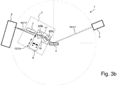
- Fig. 3b shows an alternative embodiment of an X-ray diffractometer 1 according to the invention, similar to the FIGS. 1 . 2 and 3a shown; Therefore, only the essential differences are explained in more detail.
- the adjustment system 14 of the X-ray diffractometer 1 comprises only the switching system 13 of the X-ray optics assembly 3; In particular, no primary side carriage is needed.
- the carriage 8 is again in the second movement position.
- the x-ray beam of the third beam path 17 reflected and parallelized at the multi-layer mirror 7 here enters a monochromator 9 comprising a first channel-cut crystal 9b and a second channel-cut crystal 9c arranged one behind the other (Bartels arrangement). so that an offset of the X-ray beam by the first channel-cut crystal 9b is accurately reversed by the second channel-cut crystal 9c.
- the two channel-cut crystals 9b, 9c are firmly oriented relative to one another, and both travel with the carriage 8; typically, the two channel-cut crystals 9b, 9c are separately adjustable on the carriage 8.
- the third beam path 17 therefore differs from the second beam path 16 (shown in thin dotted lines) only over a small section; in particular run the second beam path 16 and the third beam path 17 on the output side of the X-ray optics assembly 3 equal.
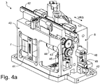
- An embodiment of an X-ray optics assembly 3 according to the invention, as used in the X-ray diffractometer of Fig. 1 . 2 . 3a can be installed is in Fig. 4a in a schematic oblique view with a main body 40 in the foreground and in Fig. 4b shown in a schematic oblique view with the carriage 8 in the foreground.
- a double slot diaphragm 41 is provided here, with a slot for the first beam path and a further slot for the second and third beam paths.
- guides 42 are formed, on which the carriage 8 can move along the direction of travel VRS.
- a drive spindle 43 is further formed, which is driven by a motor 44 and a gear 45. The drive spindle drives a spindle nut, which in turn is coupled to a guide pin in the carriage 8 (in Fig. 4a . 4b covered, cf. but Fig. 5 below).
- the monochromator 9 which is formed as a channel-cut crystal 9a, mounted on an adjusting unit 46 and adjustable (mostly hidden, see also Fig. 7 . Fig. 8, Fig. 9 below).
- the adjustable diaphragm system 10 is arranged on the carriage 8, that is formed here with a rotatable diaphragm 10a. Via a motor 47 and a (in Fig. 4a . 4b covered) gear, the rotatable aperture 10a can be rotated.
- the X-ray optics assembly 3 further has two fine thread spindles 48, 49, are formed on the adjustable end stops for the carriage 8 (see Fig. 6 below).
- Fig. 4c is a cross section through the X-ray optics assembly 3 of Fig. 4a . 4b shown at the height of the beam paths.
- an X-ray beam (not shown) may be reflected (and thereby parallelized) at the multilayer mirror 7, and then passed through the channel-cut crystal 9a to the sample position (not shown) propagate.
- the rotatable diaphragm 10a has moved out of the beam path here.
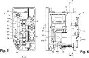
- the Fig. 5 shows a cross section through the X-ray optics assembly 3 of Fig. 4a .
- Fig. 4b at the height of the drive spindle 43.
- a spindle nut 50 On a thread (not shown in detail) of the drive spindle 43 is a spindle nut 50 which is rotatably guided on the base body 40, so that the spindle nut 50 upon rotation of the drive spindle 43 along the spindle axis (in Fig. 5 from top to bottom).
- the spindle nut 50 is coupled via a driver 51 which projects into a recess of the spindle nut 50, to a guide pin 52, which in turn in the carriage 8 along a sliding direction SRF in a corresponding bore 57 of the carriage 8 is movable.
- the driver 51 is fixedly connected to the guide pin 52 and projects from this side.
- the guide pin 52 can be moved in the bore 57 of the carriage 8 against contact elements 53, 54, which are also movable in the bore 57 in the sliding direction SRF.
- the contact elements 53, 54 are supported on the slide 8 via first spring elements 55, 56 (more about the clamping mechanism of the slide 8 in FIG Fig. 10a-10c below).
- the Fig. 6 Illustrates in a side view of the X-ray optics assembly 3, the adjustable, mutual stops (end stops) of the base body 40 and carriage 8 by means of fine-thread spindles 48, 49th
- the first fine-threaded spindle (or adjusting screw) 48 is mounted in the base body 40 and limited with its front end 48 a the travel path of the carriage 8 in Fig. 6 down by abutment against a stop element 60 (shown hatched), which is formed on the carriage 8.
- a stop element 60 shown hatched
- the second fine thread spindle (or adjusting screw) 49 is mounted in the carriage 8. Its front end 49 a limits the travel path of the carriage 8 in FIG Fig. 6 upward by abutment against a stop element 61 (shown hatched), which is formed on the base body 40. By screwing or unscrewing the fine thread spindle 49, the first movement position of the carriage 8 relative to the base body 40 can be defined or changed (and thus the position of the rotatable diaphragm adjusted). In the shown position of movement of the carriage 8, the stop element 61 is just far away from the front end 49a.
- Fig. 6 is also the cutting plane A of Fig. 5 located.
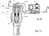
- the Fig. 7 shows in a schematic longitudinal section the adjusting unit 46 of the X-ray optics assembly according to the invention of Fig. 4a .
- Fig. 4b at which the monochromator 9 is held.
- the adjusting unit 46 comprises a first connecting portion 70 from the monochromator 9 to a ball portion 71 of the adjusting unit 46, with which it is mounted.
- a second connecting portion 72 is provided which leads from the ball portion 71 for fixing an adjusting element 73 of the adjusting unit 46; the connecting portions 70, 72 are opposite each other and extend coaxially, with the center M of the ball portion 71 on its common component axis.
- the connecting sections 70, 72 and the ball section 71 are also referred to overall as a retaining element 69.
- the adjusting element 73 is designed here as a laterally projecting adjusting lever 73a.
- the ball portion 71 and largely also the connecting portions 70, 72 extend in a bore 78 of the carriage eighth
- the ball portion 71 is clamped between two opposing socket members 74, 75 here in the form of tapered, perforated plastic discs.
- the lower socket element 75 rests here on the lower end of the bore 78 on the carriage 8, and the upper socket element 74 is pressed by means of second spring elements 76, here a plurality of stacked disc fields 76 a, to the ball portion 71, so that the ball portion 71 is kept virtually free of play between the socket elements 74, 75.
- the plate springs 76a are supported on a pressed into the bore 78, immovable fixing sleeve 77 from.
- the monochromator 9 could basically be rotated by means of the adjusting unit 46 with respect to three orthogonal axes x, y, z passing through the center M of the ball portion 71 or to be pivoted (three degrees of freedom).
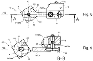
- Fig. 7 According to the invention is a degree of freedom, in the illustrated design of Fig. 7 the rotation about the z-axis, blocked, as well as from the supervision of Fig. 8 and the stepped sectional view of Fig. 9 (see sectional plane B in Fig. 7 ) becomes clear.
- mutually parallel side surfaces 80, 81 of the adjusting lever 73a are opposite, mutually parallel guide portions 82, 83 of a guide assembly 84, which is designed here as a locking sleeve 84a.
- the adjusting lever 73a or the adjusting unit 46 can be pivoted parallel to a guide plane FEB or about the y-axis; the y-axis is perpendicular to the guide plane FEB.
- the locking sleeve 84a in turn is rotatably mounted on the carriage 8 about the x-axis. Accordingly, the adjusting lever 73a or the adjusting unit 46 can be pivoted overall about the x-axis; the x-axis is parallel to the guide plane FEB.
- the side surfaces 80, 81 which lie in the direction of the z-axis next to (spaced from) the x-axis, thereby take the guide assembly 84 with.
- the guide assembly 84 with the guide portions 82, 83 blocks pivoting of the adjustment unit 46 about the z-axis.
- the guide portions 82, 83 are (here in the direction of the x-axis) spaced from the z-axis.
- the second connecting portion 72 having a circular cross section protrudes through a slot 85 of the locking sleeve 84 a, which is elongated in the direction of the z-axis, and on the second connecting portion 72 bears on two sides. As a result, the adjusting unit 46 is additionally guided.
- FIGS. 8 and 8 Also, a first adjustment mechanism 91 and a second adjustment mechanism 92 can be seen.
- the first adjustment mechanism 91 has a third spring element 95, which is designed here as a tension spring 95a, and which pulls the adjusting lever 73a via an extension screw 99 to an adjustable Justieranschlag 93, here a threaded spindle 93a, the carriage 8.
- an adjustable Justieran Kunststoff 93 here a threaded spindle 93a
- the lower, extending portion of the adjusting lever 73a can be moved substantially parallel to the x-axis, whereby a rotation of the adjusting unit 46 is effected about the y-axis.
- the lower end 94 of the threaded spindle 93a here is spherical in order to facilitate a mutual sliding of threaded spindle 93a and adjusting lever 73a when it is pivoted.
- the second adjustment mechanism 92 has a third spring element 96, which is designed here as a tension spring 96a, and the adjusting lever 73a via the extension screw 99 to an adjustable Justieranschlag 97, here a threaded spindle 97a, the slide 8 pulls.
- an adjustable Justieran Kunststoff 97 here a threaded spindle 97a
- the lower, extending part of the adjusting lever 73a can be moved substantially parallel to the y-axis, whereby a rotation of the adjusting unit 46 is effected about the x-axis.
- the front end 98 of the threaded spindle 97a here is spherical in order to facilitate a mutual sliding of threaded spindle 97a and adjusting lever 73a when it is pivoted.
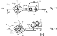
- FIG. 11 An alternative embodiment of the guide assembly 84 for an adjusting element 46 is in the Fig. 11 (in longitudinal section), Fig. 12 (in supervision) and Fig . 13 (in the stepped cross section, see level B in Fig. 11 ), which are largely the representations of Fig. 7 . FIGS. 8 and 9 accordingly, so that only the essential differences are discussed here.
- the guide arrangement 84 is here designed as a slide 8 in the slide 8 rotatable locking disc 84 b, which is formed with a slot 110.
- the slot 110 extends in a direction parallel to the z-axis.
- the opposite, parallel longitudinal sides of the oblong hole 110 form guide sections 82, 83, which bear against a circular-cylindrical region 111 of the adjusting unit 46 on both sides. It should be noted that it is sufficient if the adjusting unit 46 bears against the guide sections 82, 83 with two sufficiently large circular cylinder jacket surface sections, but usually a circumferential circular cylindrical section 111 (in which the necessary circular cylinder jacket surface sections are integrated) is easier to manufacture.
- the circular cylindrical portion 111 is formed here on the second connecting portion 72.
- a cylinder axis ZA of the circular-cylindrical region 111 runs coaxially with the x-axis.
- the adjusting unit 46 is in the slot 111 along the guide portions 82, 83 parallel to the guide plane FEB, ie about the y-axis, pivotable. Furthermore, the adjusting unit 46 is rotatable about the x-axis or about the cylinder axis ZA. On the other hand, pivoting about the z-axis is blocked by the bearing of the adjusting unit 46 on the guide sections 82, 83 which are spaced apart from the z-axis (here in the x-direction).
- adjusting element 73 which in turn is designed here as adjusting lever, can in the same way with adjusting mechanisms 91, 92 as in Fig. 7 .
- FIGS. 8 and 9 shown done.
- FIGS 10a-10c illustrate a tensioning mechanism with which the carriage 8 of the X-ray optics assembly according to the invention of Fig. 4a . 4b between end stops 100, 101 along a travel direction VRS relative to the base body can be moved.
- the end stops 100, 101 are formed by, for example, fine-thread spindles 48, 49, and in FIG Fig. 10a-10c are shown only schematically.
- the Fig. 10a first shows the carriage 8 in a middle position.
- the first spring elements 55, 56 are further arranged, which are clamped between fixed in the carriage 8 end members 102, 103 and the sliding in the sliding direction SRF contact elements 53, 54.
- the abutment elements 53, 54 press axially against the guide pin 52 axially from both sides; the first spring elements 55, 56 are in their almost relaxed position.
- the guide pin 52 has the in Fig. 10a downwardly projecting driver 51, with the force on the guide pin 52 of the drive spindle (not shown, see Fig. 5 ) can be transmitted or with the guide pin 52 can be moved in the sliding direction SRF.
- the abutment elements 53, 54 are limited in the embodiment shown by transverse bolts 104 in their travel in the carriage 8 by elongated holes 105, in particular on the guide pin 52 ("blocking elements" 53, 54).
- the abutment element 53 loses contact with the guide pin 52 by a guide bolt-side locking stop already when a small part (typically less than 20%) of the compression travel EF is covered by the guide pin 52.
- a mutual cancellation of the effects of the spring elements 55, 56 during the movement of the guide pin 52 is largely prevented.
- the compression travel EF is typically approximately chosen or planned (for example by the control of the drive spindle) that this is about half of the available due to the slots 105 spring stroke FH to the largest possible tolerance in the (actual) setting of the Either way EF available.
- the spring stroke FH and the compression travel EF are designed so that the carriage 8 in the end position (at the end stop 100, 101) can be adjusted by up to ⁇ 1.5 mm and still enough pressure on the carriage 8 acts;
- the spring stroke FH be at least 4.0 mm
- the compression travel EF be selected to at least 2.0 mm.
- a holding element 141 is held firmly in the bore 142 of a hinge pin 143.
- the hinge pin 143 has spherically rounded ends 144, 145 and is held (clamped) between two disc rings 146, 147, which in turn are secured to the carriage (not shown).
- the disk rings 146, 147 each have, on their side facing the hinge pin 143, a peripheral cut-out 148 which is circular in cross-section.
- the adjustment unit 46 may rotate about the x-axis extending along the axis of the support member 141, and also rotate about the y-axis that extends along the axis of the hinge pin 143. Blocked, however, is a pivoting about the z-axis (perpendicular to the plane of the drawing, through the center ZE of the hinge pin 143).
- an adjusting element can be attached, such as an adjusting lever (not shown).
Landscapes
- Physics & Mathematics (AREA)
- Chemical & Material Sciences (AREA)
- Spectroscopy & Molecular Physics (AREA)
- Engineering & Computer Science (AREA)
- General Engineering & Computer Science (AREA)
- High Energy & Nuclear Physics (AREA)
- Life Sciences & Earth Sciences (AREA)
- Health & Medical Sciences (AREA)
- Crystallography & Structural Chemistry (AREA)
- Analytical Chemistry (AREA)
- Biochemistry (AREA)
- General Health & Medical Sciences (AREA)
- General Physics & Mathematics (AREA)
- Immunology (AREA)
- Pathology (AREA)
- Analysing Materials By The Use Of Radiation (AREA)
Applications Claiming Priority (2)
| Application Number | Priority Date | Filing Date | Title |
|---|---|---|---|
| DE102015226101.8A DE102015226101A1 (de) | 2015-12-18 | 2015-12-18 | Röntgenoptik-Baugruppe mit Umschaltsystem für drei Strahlpfade und zugehöriges Röntgendiffraktometer |
| EP16203204.9A EP3190593B1 (fr) | 2015-12-18 | 2016-12-09 | Module d'optique en rayons x comprenant un système de transfert pour trois trajets de rayonnement et diffractomètre |
Related Parent Applications (2)
| Application Number | Title | Priority Date | Filing Date |
|---|---|---|---|
| EP16203204.9A Division EP3190593B1 (fr) | 2015-12-18 | 2016-12-09 | Module d'optique en rayons x comprenant un système de transfert pour trois trajets de rayonnement et diffractomètre |
| EP16203204.9A Division-Into EP3190593B1 (fr) | 2015-12-18 | 2016-12-09 | Module d'optique en rayons x comprenant un système de transfert pour trois trajets de rayonnement et diffractomètre |
Publications (2)
| Publication Number | Publication Date |
|---|---|
| EP3441981A1 true EP3441981A1 (fr) | 2019-02-13 |
| EP3441981B1 EP3441981B1 (fr) | 2020-03-18 |
Family
ID=57542808
Family Applications (2)
| Application Number | Title | Priority Date | Filing Date |
|---|---|---|---|
| EP16203204.9A Active EP3190593B1 (fr) | 2015-12-18 | 2016-12-09 | Module d'optique en rayons x comprenant un système de transfert pour trois trajets de rayonnement et diffractomètre |
| EP18194157.6A Active EP3441981B1 (fr) | 2015-12-18 | 2016-12-09 | Module d'optique en rayons x comprenant un système de transfert pour trois trajets de rayonnement et rotule et diffractomètre correspondant |
Family Applications Before (1)
| Application Number | Title | Priority Date | Filing Date |
|---|---|---|---|
| EP16203204.9A Active EP3190593B1 (fr) | 2015-12-18 | 2016-12-09 | Module d'optique en rayons x comprenant un système de transfert pour trois trajets de rayonnement et diffractomètre |
Country Status (4)
| Country | Link |
|---|---|
| US (1) | US10429326B2 (fr) |
| EP (2) | EP3190593B1 (fr) |
| JP (1) | JP6716441B2 (fr) |
| DE (1) | DE102015226101A1 (fr) |
Cited By (2)
| Publication number | Priority date | Publication date | Assignee | Title |
|---|---|---|---|---|
| EP3754328A3 (fr) * | 2019-06-18 | 2020-12-30 | Bruker AXS GmbH | Dispositif d'ajustement et de changement de récepteurs de rayonnement |
| WO2021254614A1 (fr) * | 2020-06-18 | 2021-12-23 | Trumpf Lasersystems For Semiconductor Manufacturing Gmbh | Ensemble optique réglable |
Families Citing this family (25)
| Publication number | Priority date | Publication date | Assignee | Title |
|---|---|---|---|---|
| CN110430750B (zh) | 2017-08-03 | 2022-08-09 | 古泽洋将 | 水生生物跳出防止装置 |
| JP6937025B2 (ja) * | 2018-03-20 | 2021-09-22 | 株式会社リガク | X線回折装置 |
| JP6871629B2 (ja) * | 2018-06-29 | 2021-05-12 | 株式会社リガク | X線分析装置及びその光軸調整方法 |
| CN108838561B (zh) * | 2018-07-02 | 2020-10-23 | 南京光宝光电科技有限公司 | 一种用于晶体快速准确定向激光切割的装置及切割方法 |
| EP3603516A1 (fr) * | 2018-08-02 | 2020-02-05 | Siemens Healthcare GmbH | Dispositif à rayons x et procédé de fonctionnement du dispositif à rayons x |
| DE112019004478T5 (de) * | 2018-09-07 | 2021-07-08 | Sigray, Inc. | System und verfahren zur röntgenanalyse mit wählbarer tiefe |
| US11467103B2 (en) * | 2019-03-29 | 2022-10-11 | Applied Science Laboratory Co., Ltd. | X-ray analyzer |
| KR102621750B1 (ko) * | 2019-06-24 | 2024-01-05 | 에스엠에스 그룹 게엠베하 | 다결정 제품의 소재 특성 측정 장치 및 방법 |
| AT523121B1 (de) | 2019-10-21 | 2021-12-15 | Anton Paar Gmbh | Röntgenvorrichtung mit mehreren Strahlpfaden |
| EP3845891B1 (fr) * | 2019-12-30 | 2022-02-09 | Xenocs SAS | Appareil de diffusion de rayons x |
| KR102927910B1 (ko) | 2020-12-07 | 2026-02-19 | 시그레이, 아이엔씨. | 투과 x-선 소스를 이용한 고처리량 3D x-선 이미징 시스템 |
| US12480892B2 (en) | 2020-12-07 | 2025-11-25 | Sigray, Inc. | High throughput 3D x-ray imaging system using a transmission x-ray source |
| EP4095522B1 (fr) * | 2021-05-25 | 2023-08-16 | Xenocs SAS | Appareil et procédé de diffusion de rayons x |
| CN118541772A (zh) | 2022-01-13 | 2024-08-23 | 斯格瑞公司 | 用于生成高通量低能量x射线的微焦x射线源 |
| US12360067B2 (en) | 2022-03-02 | 2025-07-15 | Sigray, Inc. | X-ray fluorescence system and x-ray source with electrically insulative target material |
| DE112023001408T5 (de) | 2022-03-15 | 2025-02-13 | Sigray, Inc. | System und verfahren für die kompakte laminographie unter verwendung einer mikrofokus-transmissionsröntgenquelle und eines röntgendetektors mit variabler vergrösserung |
| DE112023002079T5 (de) | 2022-05-02 | 2025-02-27 | Sigray, Inc. | Sequenzielles wellenlängendispersives röntgenspektrometer |
| DE102022213078A1 (de) * | 2022-12-05 | 2024-05-02 | Carl Zeiss Smt Gmbh | Messvorrichtung zur Vermessung von Reflexionseigenschaften |
| WO2024173256A1 (fr) | 2023-02-16 | 2024-08-22 | Sigray, Inc. | Système détecteur de rayons x avec au moins deux diffracteurs de bragg plats empilés |
| US12181423B1 (en) | 2023-09-07 | 2024-12-31 | Sigray, Inc. | Secondary image removal using high resolution x-ray transmission sources |
| WO2025101530A1 (fr) | 2023-11-07 | 2025-05-15 | Sigray, Inc. | Système et procédé de spectroscopie d'absorption des rayons x utilisant des informations spectrales provenant de deux plans orthogonaux |
| WO2025151383A1 (fr) | 2024-01-08 | 2025-07-17 | Sigray, Inc. | Système d'analyse par rayons x à faisceau de rayons x focalisé et à microscope non à rayons x |
| WO2025155719A1 (fr) | 2024-01-18 | 2025-07-24 | Sigray, Inc. | Réseau séquentiel de détecteurs d'imagerie par rayons x |
| WO2025174966A1 (fr) | 2024-02-15 | 2025-08-21 | Sigray, Inc. | Système et procédé de génération d'un faisceau de rayons x focalisé |
| CN120948519B (zh) * | 2025-10-20 | 2026-01-27 | 中科先进技术温州研究院 | 一种多几何构型衍射引导装置及x射线衍射设备 |
Citations (8)
| Publication number | Priority date | Publication date | Assignee | Title |
|---|---|---|---|---|
| US5475728A (en) * | 1992-08-03 | 1995-12-12 | Waterloo Scientific Inc. | Eucentric motion system |
| JPH0949811A (ja) * | 1995-08-08 | 1997-02-18 | Rigaku Corp | X線回折装置の光学系切換装置 |
| US6359964B1 (en) | 1998-11-25 | 2002-03-19 | U.S. Philips Corporation | X-ray analysis apparatus including a parabolic X-ray mirror and a crystal monochromator |
| EP1324023A2 (fr) * | 2001-12-28 | 2003-07-02 | Rigaku Corporation | Appareil à diffraction de rayons X |
| WO2003091716A1 (fr) * | 2002-04-26 | 2003-11-06 | Council For The Central Laboratory Of The Research | Porte-echantillon pour goniometre, dote d'un joint a rotule pour aligner un echantillon par rapport a un faisceau de rayonnement |
| US20040042584A1 (en) | 2002-09-03 | 2004-03-04 | Blank Basil Eric | Low-cost, high precision goniometric stage for x-ray diffractography |
| EP1912061A1 (fr) | 2006-10-10 | 2008-04-16 | Rigaku Corporation | Système optique pour rayons X |
| DE102009047672A1 (de) | 2009-12-08 | 2011-06-09 | Bruker Axs Gmbh | Röntgenoptischer Aufbau mit zwei fokussierenden Elementen |
Family Cites Families (25)
| Publication number | Priority date | Publication date | Assignee | Title |
|---|---|---|---|---|
| US4462689A (en) * | 1982-07-09 | 1984-07-31 | Baker Manufacturing Company | Wide band scanning monochromator |
| US4481653A (en) * | 1982-08-11 | 1984-11-06 | The Board Of Trustees Of The Leland Stanford Junior University | Tunable X-ray monochromator using transmission gratings |
| NL8300420A (nl) * | 1983-02-04 | 1984-09-03 | Philips Nv | Roentgen analyse apparaat. |
| JP3059235B2 (ja) * | 1991-04-11 | 2000-07-04 | 理学電機株式会社 | X線回折装置用モノクロメータ |
| BE1007349A3 (nl) * | 1993-07-19 | 1995-05-23 | Philips Electronics Nv | Asymmetrische 4-kristalmonochromator. |
| WO1995005725A1 (fr) * | 1993-08-16 | 1995-02-23 | Commonwealth Scientific And Industrial Research Organisation | Optique amelioree pour rayons x destinee notamment a l'imagerie a contraste de phase |
| JPH09222401A (ja) * | 1996-02-16 | 1997-08-26 | Rigaku Corp | 微小領域x線回折装置 |
| DE19833524B4 (de) * | 1998-07-25 | 2004-09-23 | Bruker Axs Gmbh | Röntgen-Analysegerät mit Gradienten-Vielfachschicht-Spiegel |
| JP3531098B2 (ja) * | 1998-12-28 | 2004-05-24 | 理学電機工業株式会社 | 蛍光x線分析装置 |
| JP2001272358A (ja) * | 2000-03-24 | 2001-10-05 | Nikon Corp | X線試料検査装置 |
| JP4313844B2 (ja) * | 2000-05-31 | 2009-08-12 | 株式会社リガク | チャンネルカットモノクロメータ |
| DE10141958B4 (de) * | 2001-08-28 | 2006-06-08 | Bruker Axs Gmbh | Röntgen-Diffraktometer |
| JP4019029B2 (ja) * | 2002-09-03 | 2007-12-05 | 株式会社リガク | 平行x線ビームの取り出し方法及び装置並びにx線回折装置 |
| JP3697246B2 (ja) * | 2003-03-26 | 2005-09-21 | 株式会社リガク | X線回折装置 |
| JP3919775B2 (ja) * | 2004-07-15 | 2007-05-30 | 株式会社リガク | X線反射率測定方法及び装置 |
| JP2007010483A (ja) * | 2005-06-30 | 2007-01-18 | Rigaku Corp | X線ビーム処理装置及びx線分析装置 |
| EP1942336B1 (fr) * | 2005-09-05 | 2014-11-05 | Rigaku Corporation | Procédé et dispositif de jugement de polarité d'échantillon monocristallin |
| JP4773899B2 (ja) * | 2006-06-29 | 2011-09-14 | 株式会社リガク | X線分光測定方法およびx線分光装置 |
| JP4861283B2 (ja) * | 2007-09-28 | 2012-01-25 | 株式会社リガク | X線回折装置およびx線回折方法 |
| US20130114157A1 (en) * | 2011-11-04 | 2013-05-09 | Alex K. Deyhim | Silicon focusing mirror system |
| JP6048867B2 (ja) * | 2012-04-17 | 2016-12-21 | 国立大学法人大阪大学 | X線光学システム |
| US9269468B2 (en) * | 2012-04-30 | 2016-02-23 | Jordan Valley Semiconductors Ltd. | X-ray beam conditioning |
| JP6168753B2 (ja) * | 2012-11-12 | 2017-07-26 | キヤノン株式会社 | 演算装置、演算プログラム、x線測定システム、およびx線測定方法 |
| JP5971763B2 (ja) * | 2013-04-17 | 2016-08-17 | 株式会社リガク | X線光学部品装置及びx線分析装置 |
| JP6292988B2 (ja) * | 2014-06-12 | 2018-03-14 | キヤノン株式会社 | 物体情報取得方法及び物体情報取得装置 |
-
2015
- 2015-12-18 DE DE102015226101.8A patent/DE102015226101A1/de not_active Withdrawn
-
2016
- 2016-12-06 US US15/370,047 patent/US10429326B2/en active Active
- 2016-12-09 EP EP16203204.9A patent/EP3190593B1/fr active Active
- 2016-12-09 EP EP18194157.6A patent/EP3441981B1/fr active Active
- 2016-12-13 JP JP2016241302A patent/JP6716441B2/ja active Active
Patent Citations (9)
| Publication number | Priority date | Publication date | Assignee | Title |
|---|---|---|---|---|
| US5475728A (en) * | 1992-08-03 | 1995-12-12 | Waterloo Scientific Inc. | Eucentric motion system |
| JPH0949811A (ja) * | 1995-08-08 | 1997-02-18 | Rigaku Corp | X線回折装置の光学系切換装置 |
| US6359964B1 (en) | 1998-11-25 | 2002-03-19 | U.S. Philips Corporation | X-ray analysis apparatus including a parabolic X-ray mirror and a crystal monochromator |
| EP1324023A2 (fr) * | 2001-12-28 | 2003-07-02 | Rigaku Corporation | Appareil à diffraction de rayons X |
| US6807251B2 (en) | 2001-12-28 | 2004-10-19 | Rigaku Corporation | X-ray diffraction apparatus |
| WO2003091716A1 (fr) * | 2002-04-26 | 2003-11-06 | Council For The Central Laboratory Of The Research | Porte-echantillon pour goniometre, dote d'un joint a rotule pour aligner un echantillon par rapport a un faisceau de rayonnement |
| US20040042584A1 (en) | 2002-09-03 | 2004-03-04 | Blank Basil Eric | Low-cost, high precision goniometric stage for x-ray diffractography |
| EP1912061A1 (fr) | 2006-10-10 | 2008-04-16 | Rigaku Corporation | Système optique pour rayons X |
| DE102009047672A1 (de) | 2009-12-08 | 2011-06-09 | Bruker Axs Gmbh | Röntgenoptischer Aufbau mit zwei fokussierenden Elementen |
Non-Patent Citations (3)
| Title |
|---|
| "Precision Mechanical Design of an UHV-Compatible Artificial Channel-Cut X-ray Monochromator", SPIE, PO BOX 10 BELLINGHAM WA 98227-0010 USA, 2007, XP040243982 * |
| FUJII Y ET AL: "A COMPACT ULTRAHIGH VACUUM X-RAY DIFFRACTOMETER FOR SURFACE GLANCING SCATTERING USING A ROTATING-ANODE SOURCE", REVIEW OF SCIENTIFIC INSTRUMENTS, AIP, MELVILLE, NY, US, vol. 68, no. 5, 1 May 1997 (1997-05-01), pages 1975 - 1979, XP000723504, ISSN: 0034-6748, DOI: 10.1063/1.1148085 * |
| Y. FUJII ET AL., REV. SCI. INSTRUM., vol. 68, no. 5, May 1997 (1997-05-01), pages 1975 - 1979 |
Cited By (3)
| Publication number | Priority date | Publication date | Assignee | Title |
|---|---|---|---|---|
| EP3754328A3 (fr) * | 2019-06-18 | 2020-12-30 | Bruker AXS GmbH | Dispositif d'ajustement et de changement de récepteurs de rayonnement |
| US11307155B2 (en) | 2019-06-18 | 2022-04-19 | Bruker Axs Gmbh | Device for adjusting and exchanging beamstops |
| WO2021254614A1 (fr) * | 2020-06-18 | 2021-12-23 | Trumpf Lasersystems For Semiconductor Manufacturing Gmbh | Ensemble optique réglable |
Also Published As
| Publication number | Publication date |
|---|---|
| JP6716441B2 (ja) | 2020-07-01 |
| US10429326B2 (en) | 2019-10-01 |
| EP3190593A2 (fr) | 2017-07-12 |
| EP3441981B1 (fr) | 2020-03-18 |
| DE102015226101A1 (de) | 2017-06-22 |
| JP2017151082A (ja) | 2017-08-31 |
| EP3190593A3 (fr) | 2017-11-08 |
| US20170176356A1 (en) | 2017-06-22 |
| EP3190593B1 (fr) | 2019-02-13 |
Similar Documents
| Publication | Publication Date | Title |
|---|---|---|
| EP3190593B1 (fr) | Module d'optique en rayons x comprenant un système de transfert pour trois trajets de rayonnement et diffractomètre | |
| DE102009006984B4 (de) | Röntgen-Mehrkanal-Spektrometer | |
| EP1288652B1 (fr) | Diffractomètre à rayons X avec dispositifs optiques de rayons X pour la génération de plusieurs trajéctoires de rayons X | |
| DE3027461C2 (de) | Verstellvorrichtung für einen Objekttisch eines optischen Instruments | |
| DE60035876T2 (de) | Mikrostrahl-Kollimator für Hochauflösungs-Röntgenstrahl-Beugungsanalyse mittels konventionellen Diffraktometern | |
| DE60302383T2 (de) | Röntgendiffraktometer | |
| EP1843184B1 (fr) | Dispositif et procédé destinés à l'ajustement d'un miroir pour rayons-x | |
| DE102008060070B4 (de) | Röntgenoptisches Element und Diffraktometer mit einer Sollerblende | |
| EP0364794A2 (fr) | Dispositif d'illumination pour un microscope d'opération | |
| DE102011014835B4 (de) | Vorrichtung zum Verstellen einer Steuerfläche eines Fluggerätemodells, Steuerflächeneinheit, Fluggerätemodell und Verwendung eines Fluggerätemodells | |
| EP0055209A2 (fr) | Dispositif pour faire tourner des faisceaux lumineux | |
| DE102022105838B3 (de) | Justiereinheit für eine Röntgenoptik in einem Röntgenfluoreszenzgerät sowie Röntgenfluoreszenzgerät | |
| EP2339332B1 (fr) | Montage optique radiographique doté de deux éléments focalisant | |
| DE10139645A1 (de) | Goniometer | |
| EP2956762B1 (fr) | Dispositif d'alignement dans l'espace d'une optique à rayons x et appareillage le comprenant | |
| DE19962503B4 (de) | Röntgenfluoreszenzanalysator mit Wegumschaltvorrichtung | |
| EP1053496A1 (fr) | Douille cylindrique destinee a des composant optiques reglables | |
| EP0140836A2 (fr) | Appareil optique pour engendrer une image visuelle stéréoscopique | |
| DE202014009275U1 (de) | Strahlaufweiter und additive Fertigungsvorrichtung mit einem Strahlaufweiter | |
| DE102023118385B3 (de) | Sicherheitsvorrichtung für eine Röntgenoptik eines Röntgenfluoreszenzanalysegeräts | |
| DE2032150C3 (de) | Vorrichtung für ein Spektral Fotometer | |
| DE1284123B (de) | Monochromator fuer Roentgenstrahlen | |
| DE19947378A1 (de) | Verstellvorrichtung für ein Objektiv mit einem axial beweglichen Optikglied | |
| DE4114582C2 (de) | Vorrichtung zur Aufnahme eines Prüflings in einem stationären Diffraktometer | |
| WO2024165472A1 (fr) | Dispositif et procédé de mesure d'erreurs d'alignement d'une source de faisceau dirigé |
Legal Events
| Date | Code | Title | Description |
|---|---|---|---|
| PUAI | Public reference made under article 153(3) epc to a published international application that has entered the european phase |
Free format text: ORIGINAL CODE: 0009012 |
|
| STAA | Information on the status of an ep patent application or granted ep patent |
Free format text: STATUS: THE APPLICATION HAS BEEN PUBLISHED |
|
| AC | Divisional application: reference to earlier application |
Ref document number: 3190593 Country of ref document: EP Kind code of ref document: P |
|
| AK | Designated contracting states |
Kind code of ref document: A1 Designated state(s): AL AT BE BG CH CY CZ DE DK EE ES FI FR GB GR HR HU IE IS IT LI LT LU LV MC MK MT NL NO PL PT RO RS SE SI SK SM TR |
|
| STAA | Information on the status of an ep patent application or granted ep patent |
Free format text: STATUS: REQUEST FOR EXAMINATION WAS MADE |
|
| 17P | Request for examination filed |
Effective date: 20190716 |
|
| RBV | Designated contracting states (corrected) |
Designated state(s): AL AT BE BG CH CY CZ DE DK EE ES FI FR GB GR HR HU IE IS IT LI LT LU LV MC MK MT NL NO PL PT RO RS SE SI SK SM TR |
|
| GRAP | Despatch of communication of intention to grant a patent |
Free format text: ORIGINAL CODE: EPIDOSNIGR1 |
|
| STAA | Information on the status of an ep patent application or granted ep patent |
Free format text: STATUS: GRANT OF PATENT IS INTENDED |
|
| INTG | Intention to grant announced |
Effective date: 20191017 |
|
| GRAS | Grant fee paid |
Free format text: ORIGINAL CODE: EPIDOSNIGR3 |
|
| GRAA | (expected) grant |
Free format text: ORIGINAL CODE: 0009210 |
|
| STAA | Information on the status of an ep patent application or granted ep patent |
Free format text: STATUS: THE PATENT HAS BEEN GRANTED |
|
| AC | Divisional application: reference to earlier application |
Ref document number: 3190593 Country of ref document: EP Kind code of ref document: P |
|
| AK | Designated contracting states |
Kind code of ref document: B1 Designated state(s): AL AT BE BG CH CY CZ DE DK EE ES FI FR GB GR HR HU IE IS IT LI LT LU LV MC MK MT NL NO PL PT RO RS SE SI SK SM TR |
|
| REG | Reference to a national code |
Ref country code: GB Ref legal event code: FG4D Free format text: NOT ENGLISH |
|
| REG | Reference to a national code |
Ref country code: DE Ref legal event code: R096 Ref document number: 502016009224 Country of ref document: DE |
|
| REG | Reference to a national code |
Ref country code: AT Ref legal event code: REF Ref document number: 1246855 Country of ref document: AT Kind code of ref document: T Effective date: 20200415 Ref country code: IE Ref legal event code: FG4D Free format text: LANGUAGE OF EP DOCUMENT: GERMAN |
|
| REG | Reference to a national code |
Ref country code: NL Ref legal event code: FP |
|
| PG25 | Lapsed in a contracting state [announced via postgrant information from national office to epo] |
Ref country code: FI Free format text: LAPSE BECAUSE OF FAILURE TO SUBMIT A TRANSLATION OF THE DESCRIPTION OR TO PAY THE FEE WITHIN THE PRESCRIBED TIME-LIMIT Effective date: 20200318 Ref country code: RS Free format text: LAPSE BECAUSE OF FAILURE TO SUBMIT A TRANSLATION OF THE DESCRIPTION OR TO PAY THE FEE WITHIN THE PRESCRIBED TIME-LIMIT Effective date: 20200318 Ref country code: NO Free format text: LAPSE BECAUSE OF FAILURE TO SUBMIT A TRANSLATION OF THE DESCRIPTION OR TO PAY THE FEE WITHIN THE PRESCRIBED TIME-LIMIT Effective date: 20200618 |
|
| PG25 | Lapsed in a contracting state [announced via postgrant information from national office to epo] |
Ref country code: BG Free format text: LAPSE BECAUSE OF FAILURE TO SUBMIT A TRANSLATION OF THE DESCRIPTION OR TO PAY THE FEE WITHIN THE PRESCRIBED TIME-LIMIT Effective date: 20200618 Ref country code: LV Free format text: LAPSE BECAUSE OF FAILURE TO SUBMIT A TRANSLATION OF THE DESCRIPTION OR TO PAY THE FEE WITHIN THE PRESCRIBED TIME-LIMIT Effective date: 20200318 Ref country code: SE Free format text: LAPSE BECAUSE OF FAILURE TO SUBMIT A TRANSLATION OF THE DESCRIPTION OR TO PAY THE FEE WITHIN THE PRESCRIBED TIME-LIMIT Effective date: 20200318 Ref country code: HR Free format text: LAPSE BECAUSE OF FAILURE TO SUBMIT A TRANSLATION OF THE DESCRIPTION OR TO PAY THE FEE WITHIN THE PRESCRIBED TIME-LIMIT Effective date: 20200318 Ref country code: GR Free format text: LAPSE BECAUSE OF FAILURE TO SUBMIT A TRANSLATION OF THE DESCRIPTION OR TO PAY THE FEE WITHIN THE PRESCRIBED TIME-LIMIT Effective date: 20200619 |
|
| REG | Reference to a national code |
Ref country code: LT Ref legal event code: MG4D |
|
| PG25 | Lapsed in a contracting state [announced via postgrant information from national office to epo] |
Ref country code: PT Free format text: LAPSE BECAUSE OF FAILURE TO SUBMIT A TRANSLATION OF THE DESCRIPTION OR TO PAY THE FEE WITHIN THE PRESCRIBED TIME-LIMIT Effective date: 20200812 Ref country code: EE Free format text: LAPSE BECAUSE OF FAILURE TO SUBMIT A TRANSLATION OF THE DESCRIPTION OR TO PAY THE FEE WITHIN THE PRESCRIBED TIME-LIMIT Effective date: 20200318 Ref country code: SM Free format text: LAPSE BECAUSE OF FAILURE TO SUBMIT A TRANSLATION OF THE DESCRIPTION OR TO PAY THE FEE WITHIN THE PRESCRIBED TIME-LIMIT Effective date: 20200318 Ref country code: LT Free format text: LAPSE BECAUSE OF FAILURE TO SUBMIT A TRANSLATION OF THE DESCRIPTION OR TO PAY THE FEE WITHIN THE PRESCRIBED TIME-LIMIT Effective date: 20200318 Ref country code: SK Free format text: LAPSE BECAUSE OF FAILURE TO SUBMIT A TRANSLATION OF THE DESCRIPTION OR TO PAY THE FEE WITHIN THE PRESCRIBED TIME-LIMIT Effective date: 20200318 Ref country code: CZ Free format text: LAPSE BECAUSE OF FAILURE TO SUBMIT A TRANSLATION OF THE DESCRIPTION OR TO PAY THE FEE WITHIN THE PRESCRIBED TIME-LIMIT Effective date: 20200318 Ref country code: RO Free format text: LAPSE BECAUSE OF FAILURE TO SUBMIT A TRANSLATION OF THE DESCRIPTION OR TO PAY THE FEE WITHIN THE PRESCRIBED TIME-LIMIT Effective date: 20200318 Ref country code: IS Free format text: LAPSE BECAUSE OF FAILURE TO SUBMIT A TRANSLATION OF THE DESCRIPTION OR TO PAY THE FEE WITHIN THE PRESCRIBED TIME-LIMIT Effective date: 20200718 |
|
| REG | Reference to a national code |
Ref country code: DE Ref legal event code: R097 Ref document number: 502016009224 Country of ref document: DE |
|
| PLBE | No opposition filed within time limit |
Free format text: ORIGINAL CODE: 0009261 |
|
| STAA | Information on the status of an ep patent application or granted ep patent |
Free format text: STATUS: NO OPPOSITION FILED WITHIN TIME LIMIT |
|
| PG25 | Lapsed in a contracting state [announced via postgrant information from national office to epo] |
Ref country code: ES Free format text: LAPSE BECAUSE OF FAILURE TO SUBMIT A TRANSLATION OF THE DESCRIPTION OR TO PAY THE FEE WITHIN THE PRESCRIBED TIME-LIMIT Effective date: 20200318 Ref country code: IT Free format text: LAPSE BECAUSE OF FAILURE TO SUBMIT A TRANSLATION OF THE DESCRIPTION OR TO PAY THE FEE WITHIN THE PRESCRIBED TIME-LIMIT Effective date: 20200318 Ref country code: DK Free format text: LAPSE BECAUSE OF FAILURE TO SUBMIT A TRANSLATION OF THE DESCRIPTION OR TO PAY THE FEE WITHIN THE PRESCRIBED TIME-LIMIT Effective date: 20200318 |
|
| 26N | No opposition filed |
Effective date: 20201221 |
|
| PG25 | Lapsed in a contracting state [announced via postgrant information from national office to epo] |
Ref country code: PL Free format text: LAPSE BECAUSE OF FAILURE TO SUBMIT A TRANSLATION OF THE DESCRIPTION OR TO PAY THE FEE WITHIN THE PRESCRIBED TIME-LIMIT Effective date: 20200318 |
|
| PG25 | Lapsed in a contracting state [announced via postgrant information from national office to epo] |
Ref country code: SI Free format text: LAPSE BECAUSE OF FAILURE TO SUBMIT A TRANSLATION OF THE DESCRIPTION OR TO PAY THE FEE WITHIN THE PRESCRIBED TIME-LIMIT Effective date: 20200318 |
|
| REG | Reference to a national code |
Ref country code: CH Ref legal event code: PL |
|
| GBPC | Gb: european patent ceased through non-payment of renewal fee |
Effective date: 20201209 |
|
| PG25 | Lapsed in a contracting state [announced via postgrant information from national office to epo] |
Ref country code: MC Free format text: LAPSE BECAUSE OF FAILURE TO SUBMIT A TRANSLATION OF THE DESCRIPTION OR TO PAY THE FEE WITHIN THE PRESCRIBED TIME-LIMIT Effective date: 20200318 |
|
| REG | Reference to a national code |
Ref country code: BE Ref legal event code: MM Effective date: 20201231 |
|
| PG25 | Lapsed in a contracting state [announced via postgrant information from national office to epo] |
Ref country code: LU Free format text: LAPSE BECAUSE OF NON-PAYMENT OF DUE FEES Effective date: 20201209 Ref country code: IE Free format text: LAPSE BECAUSE OF NON-PAYMENT OF DUE FEES Effective date: 20201209 |
|
| PG25 | Lapsed in a contracting state [announced via postgrant information from national office to epo] |
Ref country code: CH Free format text: LAPSE BECAUSE OF NON-PAYMENT OF DUE FEES Effective date: 20201231 Ref country code: LI Free format text: LAPSE BECAUSE OF NON-PAYMENT OF DUE FEES Effective date: 20201231 Ref country code: GB Free format text: LAPSE BECAUSE OF NON-PAYMENT OF DUE FEES Effective date: 20201209 |
|
| PG25 | Lapsed in a contracting state [announced via postgrant information from national office to epo] |
Ref country code: TR Free format text: LAPSE BECAUSE OF FAILURE TO SUBMIT A TRANSLATION OF THE DESCRIPTION OR TO PAY THE FEE WITHIN THE PRESCRIBED TIME-LIMIT Effective date: 20200318 Ref country code: MT Free format text: LAPSE BECAUSE OF FAILURE TO SUBMIT A TRANSLATION OF THE DESCRIPTION OR TO PAY THE FEE WITHIN THE PRESCRIBED TIME-LIMIT Effective date: 20200318 Ref country code: CY Free format text: LAPSE BECAUSE OF FAILURE TO SUBMIT A TRANSLATION OF THE DESCRIPTION OR TO PAY THE FEE WITHIN THE PRESCRIBED TIME-LIMIT Effective date: 20200318 |
|
| PG25 | Lapsed in a contracting state [announced via postgrant information from national office to epo] |
Ref country code: MK Free format text: LAPSE BECAUSE OF FAILURE TO SUBMIT A TRANSLATION OF THE DESCRIPTION OR TO PAY THE FEE WITHIN THE PRESCRIBED TIME-LIMIT Effective date: 20200318 Ref country code: AL Free format text: LAPSE BECAUSE OF FAILURE TO SUBMIT A TRANSLATION OF THE DESCRIPTION OR TO PAY THE FEE WITHIN THE PRESCRIBED TIME-LIMIT Effective date: 20200318 |
|
| PG25 | Lapsed in a contracting state [announced via postgrant information from national office to epo] |
Ref country code: BE Free format text: LAPSE BECAUSE OF NON-PAYMENT OF DUE FEES Effective date: 20201231 |
|
| REG | Reference to a national code |
Ref country code: AT Ref legal event code: MM01 Ref document number: 1246855 Country of ref document: AT Kind code of ref document: T Effective date: 20211209 |
|
| PG25 | Lapsed in a contracting state [announced via postgrant information from national office to epo] |
Ref country code: AT Free format text: LAPSE BECAUSE OF NON-PAYMENT OF DUE FEES Effective date: 20211209 |
|
| P01 | Opt-out of the competence of the unified patent court (upc) registered |
Effective date: 20231116 |
|
| PG25 | Lapsed in a contracting state [announced via postgrant information from national office to epo] |
Ref country code: IS Free format text: LAPSE BECAUSE OF NON-PAYMENT OF DUE FEES Effective date: 20200718 |
|
| PGFP | Annual fee paid to national office [announced via postgrant information from national office to epo] |
Ref country code: NL Payment date: 20251217 Year of fee payment: 10 Ref country code: FR Payment date: 20251217 Year of fee payment: 10 |
|
| PGFP | Annual fee paid to national office [announced via postgrant information from national office to epo] |
Ref country code: DE Payment date: 20251222 Year of fee payment: 10 |