EP3442064A1 - Pile unitaire de pile à combustible - Google Patents
Pile unitaire de pile à combustible Download PDFInfo
- Publication number
- EP3442064A1 EP3442064A1 EP16897927.6A EP16897927A EP3442064A1 EP 3442064 A1 EP3442064 A1 EP 3442064A1 EP 16897927 A EP16897927 A EP 16897927A EP 3442064 A1 EP3442064 A1 EP 3442064A1
- Authority
- EP
- European Patent Office
- Prior art keywords
- current collection
- collection assisting
- fuel cell
- assisting layer
- layer
- Prior art date
- Legal status (The legal status is an assumption and is not a legal conclusion. Google has not performed a legal analysis and makes no representation as to the accuracy of the status listed.)
- Granted
Links
Images







Classifications
-
- H—ELECTRICITY
- H01—ELECTRIC ELEMENTS
- H01M—PROCESSES OR MEANS, e.g. BATTERIES, FOR THE DIRECT CONVERSION OF CHEMICAL ENERGY INTO ELECTRICAL ENERGY
- H01M8/00—Fuel cells; Manufacture thereof
- H01M8/02—Details
- H01M8/0202—Collectors; Separators, e.g. bipolar separators; Interconnectors
- H01M8/023—Porous and characterised by the material
- H01M8/0232—Metals or alloys
-
- H—ELECTRICITY
- H01—ELECTRIC ELEMENTS
- H01M—PROCESSES OR MEANS, e.g. BATTERIES, FOR THE DIRECT CONVERSION OF CHEMICAL ENERGY INTO ELECTRICAL ENERGY
- H01M8/00—Fuel cells; Manufacture thereof
- H01M8/02—Details
- H01M8/0202—Collectors; Separators, e.g. bipolar separators; Interconnectors
- H01M8/0258—Collectors; Separators, e.g. bipolar separators; Interconnectors characterised by the configuration of channels, e.g. by the flow field of the reactant or coolant
-
- H—ELECTRICITY
- H01—ELECTRIC ELEMENTS
- H01M—PROCESSES OR MEANS, e.g. BATTERIES, FOR THE DIRECT CONVERSION OF CHEMICAL ENERGY INTO ELECTRICAL ENERGY
- H01M8/00—Fuel cells; Manufacture thereof
- H01M8/02—Details
- H01M8/0202—Collectors; Separators, e.g. bipolar separators; Interconnectors
- H01M8/0247—Collectors; Separators, e.g. bipolar separators; Interconnectors characterised by the form
- H01M8/0254—Collectors; Separators, e.g. bipolar separators; Interconnectors characterised by the form corrugated or undulated
-
- H—ELECTRICITY
- H01—ELECTRIC ELEMENTS
- H01M—PROCESSES OR MEANS, e.g. BATTERIES, FOR THE DIRECT CONVERSION OF CHEMICAL ENERGY INTO ELECTRICAL ENERGY
- H01M8/00—Fuel cells; Manufacture thereof
- H01M8/10—Fuel cells with solid electrolytes
- H01M8/12—Fuel cells with solid electrolytes operating at high temperature, e.g. with stabilised ZrO2 electrolyte
-
- H—ELECTRICITY
- H01—ELECTRIC ELEMENTS
- H01M—PROCESSES OR MEANS, e.g. BATTERIES, FOR THE DIRECT CONVERSION OF CHEMICAL ENERGY INTO ELECTRICAL ENERGY
- H01M8/00—Fuel cells; Manufacture thereof
- H01M8/10—Fuel cells with solid electrolytes
- H01M8/12—Fuel cells with solid electrolytes operating at high temperature, e.g. with stabilised ZrO2 electrolyte
- H01M8/1286—Fuel cells applied on a support, e.g. miniature fuel cells deposited on silica supports
-
- H—ELECTRICITY
- H01—ELECTRIC ELEMENTS
- H01M—PROCESSES OR MEANS, e.g. BATTERIES, FOR THE DIRECT CONVERSION OF CHEMICAL ENERGY INTO ELECTRICAL ENERGY
- H01M8/00—Fuel cells; Manufacture thereof
- H01M8/02—Details
- H01M8/0202—Collectors; Separators, e.g. bipolar separators; Interconnectors
- H01M8/0247—Collectors; Separators, e.g. bipolar separators; Interconnectors characterised by the form
- H01M8/0256—Vias, i.e. connectors passing through the separator material
-
- H—ELECTRICITY
- H01—ELECTRIC ELEMENTS
- H01M—PROCESSES OR MEANS, e.g. BATTERIES, FOR THE DIRECT CONVERSION OF CHEMICAL ENERGY INTO ELECTRICAL ENERGY
- H01M8/00—Fuel cells; Manufacture thereof
- H01M8/02—Details
- H01M8/0271—Sealing or supporting means around electrodes, matrices or membranes
- H01M8/0273—Sealing or supporting means around electrodes, matrices or membranes with sealing or supporting means in the form of a frame
-
- Y—GENERAL TAGGING OF NEW TECHNOLOGICAL DEVELOPMENTS; GENERAL TAGGING OF CROSS-SECTIONAL TECHNOLOGIES SPANNING OVER SEVERAL SECTIONS OF THE IPC; TECHNICAL SUBJECTS COVERED BY FORMER USPC CROSS-REFERENCE ART COLLECTIONS [XRACs] AND DIGESTS
- Y02—TECHNOLOGIES OR APPLICATIONS FOR MITIGATION OR ADAPTATION AGAINST CLIMATE CHANGE
- Y02E—REDUCTION OF GREENHOUSE GAS [GHG] EMISSIONS, RELATED TO ENERGY GENERATION, TRANSMISSION OR DISTRIBUTION
- Y02E60/00—Enabling technologies; Technologies with a potential or indirect contribution to GHG emissions mitigation
- Y02E60/30—Hydrogen technology
- Y02E60/50—Fuel cells
Definitions
- the present invention is directed to a fuel cell single cell that includes a current collection assisting layer between a cathode electrode and a separator.
- the present invention relates to a fuel cell single cell in which breakage of an electrolyte by such a current collection assisting layer is prevented.
- a solid oxide fuel cell (hereinafter also referred to simply as an "SOFC"), which is a type of fuel cells, comprises a fuel cell unit and a separator, and the fuel cell unit comprises a solid oxide electrolyte layer, a gas-permeable cathode electrode (air electrode) and a gas-permeable anode electrode (fuel electrode).
- SOFC solid oxide fuel cell
- the fuel cell generates power when a fuel gas such as hydrogen or hydrocarbon and an oxygen-containing gas are supplied respectively to the anode electrode and the cathode electrode while the solid electrolyte layer serves as a partition wall.
- a fuel gas such as hydrogen or hydrocarbon and an oxygen-containing gas
- the separator is in contact with the fuel cell unit to collect charges of the fuel cell unit and to form a fuel gas channel or an oxygen-containing gas channel between the fuel cell unit and the separator.
- the cathode electrode of the fuel cell unit is made of a metal oxide, and such metal oxides have higher electric resistance than metals.
- a current collection assisting layer is provided between the cathode electrode and the separator to form a conductive path so as to reduce the electric resistance.
- JP2008-108656A or Patent Document 1 discloses a fuel cell that comprises a current collection assisting layer that is disposed between a cathode electrode and a separator and comprises a metal felt and a metal mesh.
- Patent Document 1 JP 2008-108656A
- the current collection assisting layer often has protrusions such as burr at the ends, and the operating temperature of SOFCs is high. Therefore, thermal expansion during operation or the like may sometimes cause the separator to press the current collection assisting layer so that the protrusions damage the solid electrolyte layer. Such a damage of the solid electrolyte layer may sometimes cause cross leak of gas to reduce the power generation efficiency. Further, the protrusions may sometimes penetrate the solid electrolyte layer to make a hole to cause a short circuit.
- the present invention has been made in view of the above-described problem in the prior art, and an object thereof is to provide a fuel cell single cell in which breakage of a solid electrolyte layer by a current collection assisting layer is prevented.
- the present inventors have found that the above-described breakage of the solid electrolyte layer by the current collection assisting layer can be prevented by using the cathode electrode between the current collection assisting layer and the solid electrolyte layer as a cushion and extending the end of the cathode electrode in the planar direction outward beyond the end of the current collection assisting layer in the planar direction.
- the fuel cell single cell of the present invention comprises: a fuel cell unit in which an anode electrode, an electrolyte layer and a cathode electrode are sequentially laminated; a separator; and a current collection assisting layer disposed between the cathode electrode of the fuel cell unit and the separator.
- the separator comprises protruded portions that are in contact with the current collection assisting layer to form gas channels between the separator and the current collection assisting layer. Further, at least a part of an end of the cathode electrode in a planar direction of the cathode electrode extends outward beyond an end of the current collection assisting layer in a planar direction of the current collection assisting layer.
- the fuel cell single cell comprises the current collection assisting layer between the cathode electrode and the separator, and the end of the cathode electrode in the planar direction of the cathode electrode extend outward beyond the end of the current collection assisting layer in the planar direction of the current collection assisting layer. This allows the cathode electrode to function as a cushion to prevent a breakage of the solid electrolyte layer by the current collection assisting layer.
- FIG. 1 is an exploded view of the fuel cell single cell C of the present invention, illustrating the configuration thereof.
- the fuel cell single cell C comprises a fuel cell unit 1, a current collection assisting layer 2 and a separator 3.
- the fuel cell unit comprise an anode electrode 11, a solid electrolyte layer 12 and a cathode electrode 13, which are sequentially laminated and supported by a porous metal support.
- the fuel cell unit further comprises a frame 5 around the periphery of the porous metal support 14.
- the porous metal support 14, an anode electrode 11, the solid electrolyte layer 12 and the cathode electrode 13 are sequentially laminated in the frame 5 in the area illustrated by the dashed line in FIG. 1 .
- the current collection assisting layer 2 and the separator 3 are sequentially laminated on the cathode side of the fuel cell unit 1.
- the frame 5 and the separator 3 have a rectangular shape with approximately the same length and width.
- the fuel cell unit 1, the frame 5 and the separator 3 are laminated and joined to each other to form the fuel cell single cell C.
- the separator 3 has a corrugated transverse cross section at the center part corresponding to the fuel cell unit 1.
- the corrugation extends in the longitudinal direction as illustrated in FIG. 1 . Accordingly, protruded portions 31 of the corrugation of the separator 3 are in contact with the current collection assisting layer 2 to form gas channels G in the recessed portions of the corrugation.
- the fuel cell single cell C comprises manifold portions H1 to H4 that penetrate the frame 5 and the separator 3 in the laminating direction.
- An oxygen-containing gas is supplied to the cathode electrode 13 of the fuel cell unit 1, and a fuel gas is supplied to the anode electrode 11.
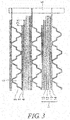
- FIG. 3 is a cross-sectional view taken along A-A' in FIG. 1 .
- the fuel cell unit, the anode electrode, the solid electrolyte layer, the cathode electrode, the porous metal support, the current collection assisting layer, the separator, a contacting material layer and a sealing member arc denoted respectively by 1, 11, 12, 13, 14, 2, 3, 4 and 6.
- the cathode electrode 13 of the present invention functions not only as a power generating component but also as a cushion that prevents protrusions of the current collection assisting layer from attacking the solid electrolyte layer 12 to damage it. At least a part of the end of the cathode electrode 13 in the planar direction of the cathode electrode extends outward beyond the end of the current collection assisting layer 2 in the planar direction of the current collection assisting layer.
- the extended length (CL) of the end of the cathode electrode that extends outward beyond the end of the current collection assisting layer 2 is longer than the thermal expansion difference between the solid electrolyte layer 12 and the current collection assisting layer 2.
- the thermal expansion of the solid electrolyte layer 12 is used as a reference because the cathode electrode 13 is joined to the solid electrolyte layer 12, and in-plane expansion and shrinkage of the cathode electrode 13 follows expansion and shrinkage of the solid electrolyte layer 12.
- the extended length (CL) is longer than the thermal expansion difference between the solid electrolyte layer 12 and the current collection assisting layer 2, the end of the cathode electrode 13 always extends beyond the end of the current collection assisting layer 2 even when the solid electrolyte layer 12 and the current collection assisting layer 2 thermally expand. This allows the cathode electrode 13 to function as a cushion so as to prevent a damage of the solid electrolyte layer 12.
- the extended length (CL) is greater than 1/1000 of the length of the cathode electrode 13 although it depends on the solid electrolyte layer 12 and the current collection assisting layer 2.
- the linear expansion coefficient of ferrite stainless steel used in the current collection assisting layer 2 is 11.9 ⁇ 10 -6 /°C (average of 0°C to 650°C), and the linear expansion coefficient of YSZ used in the solid electrolyte layer 12 is 10.5 ⁇ 10 -6 /°C. Accordingly, it is possible to prevent a damage of the solid electrolyte layer 12 when the extended length (CL) is greater than 1/1000 of the length of the cathode electrode 13.
- the upper limit of the extended length (CL) is approximately 1/1100.
- the length of the cathode electrode 13 refers to the total length of the cathode electrode 13 in the direction of extending outward beyond the end of the current collection assisting layer 2.
- Examples of materials of the cathode electrode 13 include perovskite-type oxides.
- Examples of such perovskite-type oxides include perovskite oxides (e.g. LSCF (lanthanum strontium cobalt ferrite), LSM (lanthanum strontium manganite)) and the like.
- Materials that can be used as the anode electrode 11 are metal catalysts that are composed of a metal and/or an alloy, has hydrogen-oxidizing activity and are stable in a reductive atmosphere.
- metal catalysts examples include nickel (Ni), palladium (Pd), platinum (Pt), ruthenium (Ru), Ni-Fe alloys, Ni-Co alloys, Fc-Co alloys, Ni-Cu alloys, Pd-Pt alloys and the like.
- Materials that can be used as the solid electrolyte layer 12 of the fuel cell unit 1 are oxides that have oxygen-ion conductivity and function as a solid electrolyte.
- Examples include YSZ (yttria-stabilized zirconia: Zr 1-x Y x O 2 ), SSZ (scandium-stabilized zirconia: Zr 1-x Sc x O 2 ), SDC (samarium-doped ceria: Ce 1-x Sm x O 2 ), GDC (gadolinium-doped ceria: Ce 1-x Gd x O 2 ), LSGM (lanthanum strontium magnesium gallate: La 1-x Sr x (Ga 1-y Mg y O 3 ) and the like.
- the porous metal support 14 supports the anode electrode 11, the solid electrolyte layer 12 and the cathode electrode 13 from the anode electrode 11.
- the porous metal support 14 may have many continuous pores that penetrate the porous metal support 14 in the laminating direction.
- porous metal support 14 examples include metal particles or metal fiber shaped by sintering or press working, a porous metal plate with pores formed by etching or machining, and the like.
- metal materials of the porous metal support 14 include stainless steel, iron (Fe), nickel (Ni), copper (Cu), platinum (Pt), silver (Ag) and the like.
- the fuel cell unit 1 can be formed by laminating it on one side of the porous metal support 14.
- the fuel cell unit 1 may be laminated by either dry method or wet method.
- dry methods include direct current heating deposition, ion beam deposition, reactive ion beam deposition, bipolar sputtering, magnetron sputtering, reactive sputtering, tripolar sputtering, ion beam sputtering, ion plating, hollow cathode beaming, ion beam injection, plasma CVD and any combination thereof.
- wet methods include ink-jetting, dispenser, roll coater, screen printing and any combination thereof. Slurry or paste can be used to form the films.
- the current collection assisting layer 2 is provided to form a conductive path from the cathode electrode 13 to the separator 3 to facilitate migration of charges from the cathode electrode 13 to the separator 3 so as to decrease the overall electric resistance of the fuel cell single cell.
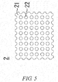
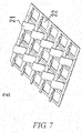
- the current collection assisting layer 2 comprises a conductive portion 21 of a metal material and gas flowing holes 22 that penetrate the current collection assisting layer 2 in the laminating direction.
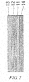
- Examples of materials that can be used as the current collection assisting layer 2 include expanded metals as illustrated in FIG. 4 , perforated metals as illustrated in FIG. 5 , metal meshes as illustrated in FIG. 6 , cantilever springs formed by cutting a flat plate as illustrated in FIG. 7 and the like, which have many gas flowing holes 22 that penetrate each of them in the laminating direction.
- the same metal materials as those of the above-described porous metal support 14 can be used for the current collection assisting layer 2.
- the size of the gas flowing holes 22 of the current collection assisting layer 2 is less than the width of the gas channels G formed by the separator 3 (described below), i.e. the intervals of the protruded portions of the corrugation of the separator that are in contact with the current collection assisting layer 2.
- the fuel cell single cell C has decreased power generation efficiency when the travel distance of charges is long in the cathode electrode and the contacting material layer.
- the current collection assisting layer 2 which has many gas flowing holes 22 that are smaller than the width of the gas channels G, charges in the cathode electrode 13 migrate to the separator 3 through the conductive portion 21 of the current collection assisting layer 2. This can reduce the travel distance of charges in the cathode electrode and the contacting material layer so as to decrease the electric resistance.
- the width of the conductive portion 21 of the current collection assisting layer 2 is within the range of 0.5 mm to 0.15 mm.
- Oxide film is readily formed in SOFCs due to its high operating temperature. In particular, oxide film is readily formed to increase the electric resistance in a cathode to which oxygen gas is supplied.
- the current collection assisting layer 2 When the width of the conductive portion 21 is less than 0.5 mm, the current collection assisting layer 2 has large surface area. Since this increases the contact area with the oxygen-containing gas, the current collection assisting layer 2 is more likely to be oxidized to increase the electric resistance.
- the oxygen-containing gas travels a long distance to reach the portions where the cathode electrode 13 is in contact with the conductive portion 21. This may make some portions of the cathode electrode 13 less available for power generation and decrease the power generation efficiency.
- the porosity of the gas flowing holes 22 of the current collection assisting layer 2 is within the range of 30% to 80%. When the porosity is less than 30%, it is difficult to supply the oxygen-containing gas to the cathode electrode 13. When the porosity is greater than 80%, charges migrate long distance in the cathode electrode and the contacting material layer.
- the separator 3 comprises continuous protruded portions.
- the protruded portions are in contact with the current collection assisting layer 2 or an adjacent fuel cell single cell C to electrically join the current collection assisting layer 2 with the adjacent fuel cell single cell C and to form the gas channels G between the current collection assisting layer 2 and the adjacent fuel cell single cell C.
- the separator 3 is joined to the current collection assisting layer 2 and to a porous metal support 14 of the adjacent fuel cell single cell C with metal joining portions 31.
- the metal joining portions 31 couple and integrate the metal materials of the current collection assisting layer 2, the separator 3 and the porous metal support 14 directly and/or via another metal material.
- the metal joining portions 31 do not comprise oxide film therein.
- the electric resistance between the current collection assisting layer 2 and the separator 3 and between the separator 3 and the porous metal support 14 of the adjacent fuel cell single cell C can be maintained at a low level, and the power generation efficiency can thus be improved.
- the metal joining portion 31 can be formed by welding or brazing.
- welding refers to melting metal parts themselves to couple and integrate the metal parts with each other.
- Brazing refers to coupling and integrating metal parts with each other by using other metal material than the metal parts to be coupled.
- the separator 3 can be formed by shaping a flat plate of a metal material into a corrugated shape by press working.
- the same materials as the above-described metal materials of the porous metal support 14 can be used as the metal material of the separator 3.
- the fuel cell single cell C of the present invention may comprise the contacting material layer 4 between the cathode electrode 13 and the current collection assisting layer 2.
- the contacting material layer 4 joins the cathode electrode 13 to the current collection assisting layer 2 in the entire surface thereof and serves as a cushion between the current collection assisting layer 2 and the solid electrolyte layer 12.
- the current collection assisting layer 2 often has an uneven surface or a warpage, which is likely to cause a winkle or warpage when it is fixed to the separator 3. Therefore, it is difficult to bring the cathode electrode 13 of the fuel cell unit C in direct contact with the current collection assisting layer 2 in the entire surface, and this results in the increased contact resistance.
- the fuel cell unit C When the current collection assisting layer 2 is strongly pressed against the cathode electrode 13 of the fuel cell unit C to bring the current collection assisting layer 2 into contact with the cathode electrode 13 in the entire surface, the fuel cell unit C may be damaged by pressing pressure, since the fuel cell unit C of the SOFC, which includes the solid electrolyte layer 12, is thin and hard, and the current collection assisting layer 2 is also hard.
- the contacting material layer 4 When the contacting material layer 4 is provided between the cathode electrode 13 and the current collection assisting layer 2, the contacting material layer 4 can absorb the unevenness or warpage of the current collection assisting layer 2 to form a flat joining surface with the cathode electrode 13. Therefore, the cathode electrode 13 and the current collection assisting layer 2 can be joined to each other well.
- the current collection assisting layer 2 can be made of a material that can be sintered along with the cathode electrode 13 to reduce the contact resistance with the cathode electrode 13.
- the metal oxides of the above-described solid oxide layer can be used. They can be used alone or as a combination of two or more.
- the current collection assisting layer 2 contains the same metal oxide as that of the cathode electrode 13, it can be integrated with the cathode electrode 13 to decrease the contact resistance. Furthermore, the current collection assisting layer 2 can maintain the decreased electric resistance for a long time since it is less likely to come apart.
- the contacting material layer 4 can be formed by mixing the above-described metal oxide particles with an organic binder, an organic solvent and the like and applying the prepared ink or paste or by forming the material into a flexible sheet or plate and cutting it into a desired shape.
- the thickness of the contacting material layer 4 is not particularly limited. It is only necessary that the contacting material layer 4 can absorb the unevenness or warpage of the current collection assisting layer to provide a flat surface on the other side that is to be joined to the cathode electrode.
- the conductive portion 21 of the current collection assisting layer 2 bites into the contacting material layer 4 to a depth less than the thickness of the contacting material layer 4. Accordingly, the cathode electrode is prevented from being damaged by the current collection assisting layer 2 that protrudes on the joining face between the contacting material layer 4 and the cathode electrode 13. As a result, it is possible to integrate the contacting material layer 4 with the cathode electrode 13 in the entire surface by sintering so as to reduce the contact resistance.
- the conductive portion 21 of the current collection assisting layer 2 bites into the contacting material layer 4 when they are joined with each other.
- the conductive portion 21 that bites into the contacting material layer 4 can reduce the contact resistance between the current collection assisting layer 2 and the contacting material layer 4 and firmly join the current collection assisting layer 2 to the contacting material layer 4.
- the contact resistance of a portion having a small contact area or oxide film causes an increase in resistance
- the overall electric resistance of the system remarkably is increased.
- the conductive portion 21 that bites into the contacting material layer 4 and joins to it in the entire surface can prevent such an increase of the electric resistance.
- ink or paste of an application liquid of the contacting material layer can be applied on the current collection assisting layer 2 so that the application liquid of the contacting material layer flows into the gas flowing holes 22. This allows forming a joining portion in which the conductive portion 21 of the current collection assisting layer 2 bites into the contacting material layer 4.
- FIG. 8 is a cross-sectional view of the fuel cell single cell according to the embodiment taken in the gas channel direction, i.e. along the line B-B' in FIG. 1 .
- protruded portions of a separator 3 are in contact with a current collection assisting layer.
- fuel gas channels are formed under the fuel cell unit 1 around the sheet, and oxygen-containing gas channels are formed on the fuel cell unit 1 in front of and behind the sheet.
- the end of the cathode electrode 13 in the upstream of the gas channel direction of the oxygen-containing gas extends outward beyond the end of current collection assisting layer 2 in the upstream of the gas channel direction of the oxygen-containing gas, i.e. is located in the upstream of the gas channel direction of the oxygen-containing gas.
- the extended length (CL) of the end of the cathode electrode that extends outward beyond the end of the current collection assisting layer 2 is as long as that in the above-described first embodiment.
- the operating temperature of SOFCs is high.
- a high-temperature gas is directed into the oxygen-containing gas channels to rapidly increase the temperature for the purpose of reducing the start-up time from a cold state, the temperature is increased from a part proximate to a manifold for supplying the oxygen-containing gas.
- the temperature is also increased from a part proximate to the manifold for supplying the oxygen-containing gas and a manifold for supplying the fuel gas, i.e. from the upstream of the gas channel direction of the oxygen-containing gas.
- the separator 3 most strongly presses the current collection assisting layer 2 in the upstream of the gas channel direction of the oxygen-containing gas.
- the end of the cathode electrode 13 in the upstream of the gas channel direction of the oxygen-containing gas extends outward beyond the end of the current collection assisting layer in the upstream of the gas channel direction. This can prevent the solid electrolyte layer 12 from being damaged in the portion that is most likely to experience thermal expansion.
- a current collection assisting layer 2 in the direction perpendicular to a gas channel direction extends outward beyond the outermost protruded portion of the separator, which forms gas channels, in the planar direction.
- FIG. 9 is a cross-sectional view taken along A-A' in FIG. 1 .
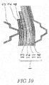
- the fuel cell unit C bends like a bimetal in a high-temperature condition as illustrated in FIG. 10 since the layers of the fuel cell unit have different coefficients of thermal expansion.
- the bending deformation of the current collection assisting layer 2 is less than the bending deformation of the fuel cell unit C due to the bending deformation of the separator 3. Accordingly, the end of the fuel cell unit C presses the current collection assisting layer 2 as illustrated by the arrows in FIG. 10 , and a reaction force of the current collection assisting layer 2 breaks a solid electrolyte layer 12 of the fuel cell unit.
- the end of the current collection assisting layer 2 is located at an outside of the outermost protruded portion of the separator 3, the end of the current collection assisting layer 2 does not resist against the bending deformation of the fuel cell unit C. This can prevent the solid electrolyte layer 12 from being damaged.
- the extended length (SL) of the end of the current collection assisting layer 2 that extends outward beyond the protruded portions of the separator 3 is preferably at least 20 times greater than the thickness (h) of the current collection assisting layer 2, although it depends on the fuel cell unit C and the current collection assisting layer 2.
- the load on the fuel cell unit C from the distorted current collection assisting layer 2 is equal to or less than one tenth of the bending stress on the fuel cell unit itself due to the thermal expansion of the fuel cell unit C. This can prevent the solid electrolyte layer 12 from being pressed and broken by the current collection assisting layer 2.
- the current collection assisting layer 2 bends like a beam with fixed ends at the outermost protruded portions of the separator 3, the load on the current collection assisting layer 2 caused by a bending deformation of the fuel cell unit C is less than the fracture stress of the fuel cell unit C. This can prevent a breakage of the fuel cell unit C.
- an end of a current collection assisting layer 2 in the direction perpendicular to the gas channel direction is fixed outside the outermost protruded portion in the planar direction of a separator.
- FIG. 11 is a cross-sectional view taken along A-A' in FIG. 1 .
- the end of the current collection assisting layer 2 is fixed outside the outermost protruded portion of the separator in the planar direction, i.e. at a location other than the protruded portions of the separator 3, with a metal joining portion 31. This can prevent the end of the current collection assisting layer 2 from attacking a solid electrolyte layer 12, so as to prevent a breakage of the solid electrolyte layer 12.
- the fuel cell single cell C of this embodiment comprises a contacting material layer 4 between a cathode electrode 13 and a current collection assisting layer 2. Further, an end of the contacting material layer 4 in the direction perpendicular to the gas channel direction, i.e. the part outside an outermost protruded portion of a separator in the planar direction, is thicker than the part inside the outermost protruded portion.
- FIG. 12 is a cross-sectional view taken along A-A' in FIG. 1 .
- the part outside the outermost protruded portion of a separator 3 that is in contact with the current collection assisting layer 2 is thicker than the inside. This can extend the distance from the end of the current collection assisting layer 2 to a solid electrolyte layer 12 and allow the contacting material layer 4 to function as a cushion, so as to prevent a breakage of the solid electrolyte layer 12.
Landscapes
- Life Sciences & Earth Sciences (AREA)
- Engineering & Computer Science (AREA)
- Manufacturing & Machinery (AREA)
- Sustainable Development (AREA)
- Sustainable Energy (AREA)
- Chemical & Material Sciences (AREA)
- Chemical Kinetics & Catalysis (AREA)
- Electrochemistry (AREA)
- General Chemical & Material Sciences (AREA)
- Fuel Cell (AREA)
Applications Claiming Priority (1)
| Application Number | Priority Date | Filing Date | Title |
|---|---|---|---|
| PCT/JP2016/061507 WO2017175371A1 (fr) | 2016-04-08 | 2016-04-08 | Pile unitaire de pile à combustible |
Publications (3)
| Publication Number | Publication Date |
|---|---|
| EP3442064A1 true EP3442064A1 (fr) | 2019-02-13 |
| EP3442064A4 EP3442064A4 (fr) | 2019-04-03 |
| EP3442064B1 EP3442064B1 (fr) | 2020-10-14 |
Family
ID=60001049
Family Applications (1)
| Application Number | Title | Priority Date | Filing Date |
|---|---|---|---|
| EP16897927.6A Active EP3442064B1 (fr) | 2016-04-08 | 2016-04-08 | Pile unitaire de pile à combustible |
Country Status (7)
| Country | Link |
|---|---|
| US (1) | US10629921B2 (fr) |
| EP (1) | EP3442064B1 (fr) |
| JP (1) | JP6677913B2 (fr) |
| CN (1) | CN108886152B (fr) |
| BR (1) | BR112018070652B1 (fr) |
| CA (1) | CA3020251C (fr) |
| WO (1) | WO2017175371A1 (fr) |
Cited By (4)
| Publication number | Priority date | Publication date | Assignee | Title |
|---|---|---|---|---|
| US20210328233A1 (en) * | 2020-04-21 | 2021-10-21 | Hamilton Sundstrand Corporation | Bulk metallic glass interconnect for high power density fuel cell |
| EP3905399A1 (fr) * | 2020-04-21 | 2021-11-03 | Hamilton Sundstrand Corporation | Pile à combustible à densité de puissance élevée |
| WO2022058300A1 (fr) * | 2020-09-17 | 2022-03-24 | Robert Bosch Gmbh | Pile à combustible pour système de pile à combustible, système de pile à combustible et procédé de fabrication d'une pile à combustible |
| EP4145571A4 (fr) * | 2020-04-30 | 2025-04-30 | Kyocera Corporation | Cellule, dispositif d'empilement de cellules, module, et dispositif de réception de module |
Families Citing this family (10)
| Publication number | Priority date | Publication date | Assignee | Title |
|---|---|---|---|---|
| KR102063060B1 (ko) * | 2017-01-31 | 2020-03-02 | 주식회사 엘지화학 | 연료전지 스택 |
| WO2019026168A1 (fr) * | 2017-08-01 | 2019-02-07 | 日産自動車株式会社 | Unité de cellule |
| US11127958B2 (en) | 2018-01-29 | 2021-09-21 | Nissan Motor Co., Ltd. | Cell unit |
| JP7236675B2 (ja) * | 2018-08-01 | 2023-03-10 | パナソニックIpマネジメント株式会社 | 固体酸化物形燃料電池セル、及び電気化学セル |
| JP7236676B2 (ja) * | 2018-08-01 | 2023-03-10 | パナソニックIpマネジメント株式会社 | 固体酸化物形燃料電池セル、及び電気化学セル |
| JP7629444B2 (ja) | 2020-03-26 | 2025-02-13 | 太陽誘電株式会社 | 固体酸化物型燃料電池、固体酸化物型燃料電池スタック、及び固体酸化物型燃料電池の製造方法 |
| WO2021221052A1 (fr) * | 2020-04-30 | 2021-11-04 | 京セラ株式会社 | Cellule, dispositif d'empilement de cellules, module et dispositif de boîtier de module |
| JP7294522B2 (ja) * | 2021-04-15 | 2023-06-20 | 日産自動車株式会社 | 燃料電池および燃料電池の製造方法 |
| JP2024027696A (ja) * | 2022-08-18 | 2024-03-01 | 東芝エネルギーシステムズ株式会社 | 電気化学セル及びセルスタック |
| JP2025021673A (ja) * | 2023-08-01 | 2025-02-14 | 東芝エネルギーシステムズ株式会社 | 固体酸化物形電気化学セルスタック |
Family Cites Families (16)
| Publication number | Priority date | Publication date | Assignee | Title |
|---|---|---|---|---|
| WO1992002057A1 (fr) * | 1990-07-24 | 1992-02-06 | Kabushiki Kaisha Toshiba | Separateur et son procede de fabrication |
| JP2001068132A (ja) | 1999-08-25 | 2001-03-16 | Tokyo Gas Co Ltd | 集電板およびそれを用いた固体電解質燃料電池 |
| US6544681B2 (en) | 2000-12-26 | 2003-04-08 | Ballard Power Systems, Inc. | Corrugated flow field plate assembly for a fuel cell |
| JP5000857B2 (ja) * | 2005-05-27 | 2012-08-15 | 日本特殊陶業株式会社 | 固体酸化物燃料電池 |
| JP5046612B2 (ja) | 2006-10-27 | 2012-10-10 | 本田技研工業株式会社 | 燃料電池 |
| JP5198797B2 (ja) * | 2007-05-23 | 2013-05-15 | 日本特殊陶業株式会社 | 固体電解質形燃料電池 |
| JP4315219B2 (ja) * | 2007-06-15 | 2009-08-19 | トヨタ自動車株式会社 | 燃料電池 |
| US8603696B2 (en) | 2007-07-19 | 2013-12-10 | Ngk Insulators, Ltd. | Reactor |
| CN102227838B (zh) * | 2008-11-28 | 2014-03-12 | 日产自动车株式会社 | 固体高分子型燃料电池 |
| JP4906891B2 (ja) | 2009-06-12 | 2012-03-28 | 本田技研工業株式会社 | 燃料電池 |
| WO2012035591A1 (fr) * | 2010-09-16 | 2012-03-22 | トヨタ自動車株式会社 | Ensemble électrode à membrane, pile à combustible utilisant celui-ci et procédé de production d'ensemble électrode à membrane |
| JP5330577B2 (ja) * | 2011-08-09 | 2013-10-30 | 日本特殊陶業株式会社 | 燃料電池セル及び燃料電池スタック |
| JP5741943B2 (ja) * | 2011-08-31 | 2015-07-01 | アイシン精機株式会社 | 固体酸化物形燃料電池装置 |
| CN103296301B (zh) * | 2012-03-02 | 2015-10-07 | 中国科学院宁波材料技术与工程研究所 | 一种阳极支撑平板式固体氧化物燃料电池无压电堆 |
| JP6118225B2 (ja) * | 2013-10-09 | 2017-04-19 | 本田技研工業株式会社 | 燃料電池用樹脂枠付き電解質膜・電極構造体 |
| JP6443615B2 (ja) * | 2014-08-11 | 2018-12-26 | 日産自動車株式会社 | 燃料電池ユニット、該燃料電池ユニットの製造方法、及び燃料電池スタック |
-
2016
- 2016-04-08 CN CN201680084346.1A patent/CN108886152B/zh active Active
- 2016-04-08 EP EP16897927.6A patent/EP3442064B1/fr active Active
- 2016-04-08 BR BR112018070652-3A patent/BR112018070652B1/pt not_active IP Right Cessation
- 2016-04-08 CA CA3020251A patent/CA3020251C/fr not_active Expired - Fee Related
- 2016-04-08 US US16/091,552 patent/US10629921B2/en active Active
- 2016-04-08 WO PCT/JP2016/061507 patent/WO2017175371A1/fr not_active Ceased
- 2016-04-08 JP JP2018510201A patent/JP6677913B2/ja active Active
Cited By (6)
| Publication number | Priority date | Publication date | Assignee | Title |
|---|---|---|---|---|
| US20210328233A1 (en) * | 2020-04-21 | 2021-10-21 | Hamilton Sundstrand Corporation | Bulk metallic glass interconnect for high power density fuel cell |
| EP3905399A1 (fr) * | 2020-04-21 | 2021-11-03 | Hamilton Sundstrand Corporation | Pile à combustible à densité de puissance élevée |
| EP3905398A1 (fr) * | 2020-04-21 | 2021-11-03 | Hamilton Sundstrand Corporation | Interconnexion en verre métallique massif pour une pile à combustible à haute densité de puissance |
| US12068509B2 (en) * | 2020-04-21 | 2024-08-20 | Hamilton Sundstrand Corporation | Bulk metallic glass interconnect for high power density fuel cell |
| EP4145571A4 (fr) * | 2020-04-30 | 2025-04-30 | Kyocera Corporation | Cellule, dispositif d'empilement de cellules, module, et dispositif de réception de module |
| WO2022058300A1 (fr) * | 2020-09-17 | 2022-03-24 | Robert Bosch Gmbh | Pile à combustible pour système de pile à combustible, système de pile à combustible et procédé de fabrication d'une pile à combustible |
Also Published As
| Publication number | Publication date |
|---|---|
| CN108886152A (zh) | 2018-11-23 |
| BR112018070652B1 (pt) | 2022-08-02 |
| JPWO2017175371A1 (ja) | 2019-02-07 |
| BR112018070652A2 (pt) | 2019-02-05 |
| CN108886152B (zh) | 2019-12-03 |
| JP6677913B2 (ja) | 2020-04-08 |
| EP3442064B1 (fr) | 2020-10-14 |
| EP3442064A4 (fr) | 2019-04-03 |
| US20190109333A1 (en) | 2019-04-11 |
| CA3020251A1 (fr) | 2017-10-12 |
| WO2017175371A1 (fr) | 2017-10-12 |
| CA3020251C (fr) | 2020-10-06 |
| US10629921B2 (en) | 2020-04-21 |
Similar Documents
| Publication | Publication Date | Title |
|---|---|---|
| EP3442064B1 (fr) | Pile unitaire de pile à combustible | |
| EP1217676B1 (fr) | Pile à combustible à oxyde solide comportant une matte à diffusion gazeuse et empilement de piles à combustible à oxydes solides comportant une telle matte et un élement d'interconnection | |
| US20050136312A1 (en) | Compliant fuel cell system | |
| JP5309487B2 (ja) | 燃料電池 | |
| US20050053819A1 (en) | Solid oxide fuel cell interconnect with catalyst coating | |
| KR20200139711A (ko) | 전기 화학 소자의 금속 지지체, 전기 화학 소자, 전기 화학 모듈, 전기 화학 장치, 에너지 시스템, 고체 산화물형 연료 전지, 고체 산화물형 전해 셀 및 금속 지지체의 제조 방법 | |
| JP2018200748A (ja) | 燃料電池ユニット | |
| JP2003115301A (ja) | 燃料電池用単セル及び固体電解質型燃料電池 | |
| US20120082920A1 (en) | Co-fired metal interconnect supported sofc | |
| JP2014123544A (ja) | 固体酸化物形燃料電池及びインターコネクタの製作方法 | |
| JP6805528B2 (ja) | 燃料電池単セル及び燃料電池スタック | |
| JP6204106B2 (ja) | 燃料電池セル及び燃料電池セルスタック | |
| JP2011048957A (ja) | 燃料電池用冷却層およびその製造方法ならびにそれを用いた燃料電池 | |
| US20070141435A1 (en) | Fuel cell with a brazed interconnect and method of assembling the same | |
| JP2005339878A (ja) | 単電池及びこの単電池を用いた固体酸化物型燃料電池 | |
| JP2005347095A (ja) | 固体酸化物形燃料電池用基板及び固体酸化物形燃料電池用セル | |
| JP2008251379A (ja) | 電気化学装置 | |
| JP6773600B2 (ja) | 電気化学反応単位および電気化学反応セルスタック | |
| JP5245205B2 (ja) | 固体酸化物形燃料電池 | |
| EP1735864B1 (fr) | Ensemble électrode électrolytique et procédé de fabrication dudit ensemble | |
| JP2008010255A (ja) | 電気化学装置 | |
| WO2017002264A1 (fr) | Pile à combustible à oxyde solide et son procédé de fabrication | |
| JP5181600B2 (ja) | 固体酸化物形燃料電池、固体酸化物形燃料電池のスタック構造、及び固体酸化物形燃料電池の製造方法 | |
| US20190157707A1 (en) | Secondary interconnect for fuel cell systems | |
| CN103187577A (zh) | 双金属集流元件及具有该双金属集流元件的燃料电池装置 |
Legal Events
| Date | Code | Title | Description |
|---|---|---|---|
| STAA | Information on the status of an ep patent application or granted ep patent |
Free format text: STATUS: THE INTERNATIONAL PUBLICATION HAS BEEN MADE |
|
| PUAI | Public reference made under article 153(3) epc to a published international application that has entered the european phase |
Free format text: ORIGINAL CODE: 0009012 |
|
| STAA | Information on the status of an ep patent application or granted ep patent |
Free format text: STATUS: REQUEST FOR EXAMINATION WAS MADE |
|
| 17P | Request for examination filed |
Effective date: 20181106 |
|
| AK | Designated contracting states |
Kind code of ref document: A1 Designated state(s): AL AT BE BG CH CY CZ DE DK EE ES FI FR GB GR HR HU IE IS IT LI LT LU LV MC MK MT NL NO PL PT RO RS SE SI SK SM TR |
|
| AX | Request for extension of the european patent |
Extension state: BA ME |
|
| A4 | Supplementary search report drawn up and despatched |
Effective date: 20190306 |
|
| RIC1 | Information provided on ipc code assigned before grant |
Ipc: H01M 8/1286 20160101ALI20190227BHEP Ipc: H01M 8/0254 20160101ALI20190227BHEP Ipc: H01M 8/0232 20160101ALI20190227BHEP Ipc: H01M 8/12 20160101AFI20190227BHEP Ipc: H01M 8/0273 20160101ALN20190227BHEP Ipc: H01M 8/0256 20160101ALN20190227BHEP |
|
| DAV | Request for validation of the european patent (deleted) | ||
| DAX | Request for extension of the european patent (deleted) | ||
| STAA | Information on the status of an ep patent application or granted ep patent |
Free format text: STATUS: EXAMINATION IS IN PROGRESS |
|
| 17Q | First examination report despatched |
Effective date: 20200102 |
|
| REG | Reference to a national code |
Ref country code: DE Ref legal event code: R079 Ref document number: 602016046056 Country of ref document: DE Free format text: PREVIOUS MAIN CLASS: H01M0008020200 Ipc: H01M0008120000 |
|
| GRAP | Despatch of communication of intention to grant a patent |
Free format text: ORIGINAL CODE: EPIDOSNIGR1 |
|
| STAA | Information on the status of an ep patent application or granted ep patent |
Free format text: STATUS: GRANT OF PATENT IS INTENDED |
|
| RIC1 | Information provided on ipc code assigned before grant |
Ipc: H01M 8/0232 20160101ALI20200615BHEP Ipc: H01M 8/0256 20160101ALN20200615BHEP Ipc: H01M 8/0254 20160101ALI20200615BHEP Ipc: H01M 8/0273 20160101ALN20200615BHEP Ipc: H01M 8/1286 20160101ALI20200615BHEP Ipc: H01M 8/12 20160101AFI20200615BHEP |
|
| INTG | Intention to grant announced |
Effective date: 20200707 |
|
| GRAS | Grant fee paid |
Free format text: ORIGINAL CODE: EPIDOSNIGR3 |
|
| GRAA | (expected) grant |
Free format text: ORIGINAL CODE: 0009210 |
|
| STAA | Information on the status of an ep patent application or granted ep patent |
Free format text: STATUS: THE PATENT HAS BEEN GRANTED |
|
| AK | Designated contracting states |
Kind code of ref document: B1 Designated state(s): AL AT BE BG CH CY CZ DE DK EE ES FI FR GB GR HR HU IE IS IT LI LT LU LV MC MK MT NL NO PL PT RO RS SE SI SK SM TR |
|
| REG | Reference to a national code |
Ref country code: GB Ref legal event code: FG4D |
|
| REG | Reference to a national code |
Ref country code: AT Ref legal event code: REF Ref document number: 1324469 Country of ref document: AT Kind code of ref document: T Effective date: 20201015 Ref country code: CH Ref legal event code: EP |
|
| REG | Reference to a national code |
Ref country code: DE Ref legal event code: R096 Ref document number: 602016046056 Country of ref document: DE |
|
| REG | Reference to a national code |
Ref country code: IE Ref legal event code: FG4D |
|
| REG | Reference to a national code |
Ref country code: AT Ref legal event code: MK05 Ref document number: 1324469 Country of ref document: AT Kind code of ref document: T Effective date: 20201014 |
|
| REG | Reference to a national code |
Ref country code: NL Ref legal event code: MP Effective date: 20201014 |
|
| PG25 | Lapsed in a contracting state [announced via postgrant information from national office to epo] |
Ref country code: PT Free format text: LAPSE BECAUSE OF FAILURE TO SUBMIT A TRANSLATION OF THE DESCRIPTION OR TO PAY THE FEE WITHIN THE PRESCRIBED TIME-LIMIT Effective date: 20210215 Ref country code: RS Free format text: LAPSE BECAUSE OF FAILURE TO SUBMIT A TRANSLATION OF THE DESCRIPTION OR TO PAY THE FEE WITHIN THE PRESCRIBED TIME-LIMIT Effective date: 20201014 Ref country code: NO Free format text: LAPSE BECAUSE OF FAILURE TO SUBMIT A TRANSLATION OF THE DESCRIPTION OR TO PAY THE FEE WITHIN THE PRESCRIBED TIME-LIMIT Effective date: 20210114 Ref country code: FI Free format text: LAPSE BECAUSE OF FAILURE TO SUBMIT A TRANSLATION OF THE DESCRIPTION OR TO PAY THE FEE WITHIN THE PRESCRIBED TIME-LIMIT Effective date: 20201014 Ref country code: GR Free format text: LAPSE BECAUSE OF FAILURE TO SUBMIT A TRANSLATION OF THE DESCRIPTION OR TO PAY THE FEE WITHIN THE PRESCRIBED TIME-LIMIT Effective date: 20210115 |
|
| REG | Reference to a national code |
Ref country code: LT Ref legal event code: MG4D |
|
| PG25 | Lapsed in a contracting state [announced via postgrant information from national office to epo] |
Ref country code: ES Free format text: LAPSE BECAUSE OF FAILURE TO SUBMIT A TRANSLATION OF THE DESCRIPTION OR TO PAY THE FEE WITHIN THE PRESCRIBED TIME-LIMIT Effective date: 20201014 Ref country code: AT Free format text: LAPSE BECAUSE OF FAILURE TO SUBMIT A TRANSLATION OF THE DESCRIPTION OR TO PAY THE FEE WITHIN THE PRESCRIBED TIME-LIMIT Effective date: 20201014 Ref country code: LV Free format text: LAPSE BECAUSE OF FAILURE TO SUBMIT A TRANSLATION OF THE DESCRIPTION OR TO PAY THE FEE WITHIN THE PRESCRIBED TIME-LIMIT Effective date: 20201014 Ref country code: PL Free format text: LAPSE BECAUSE OF FAILURE TO SUBMIT A TRANSLATION OF THE DESCRIPTION OR TO PAY THE FEE WITHIN THE PRESCRIBED TIME-LIMIT Effective date: 20201014 Ref country code: IS Free format text: LAPSE BECAUSE OF FAILURE TO SUBMIT A TRANSLATION OF THE DESCRIPTION OR TO PAY THE FEE WITHIN THE PRESCRIBED TIME-LIMIT Effective date: 20210214 Ref country code: BG Free format text: LAPSE BECAUSE OF FAILURE TO SUBMIT A TRANSLATION OF THE DESCRIPTION OR TO PAY THE FEE WITHIN THE PRESCRIBED TIME-LIMIT Effective date: 20210114 Ref country code: SE Free format text: LAPSE BECAUSE OF FAILURE TO SUBMIT A TRANSLATION OF THE DESCRIPTION OR TO PAY THE FEE WITHIN THE PRESCRIBED TIME-LIMIT Effective date: 20201014 |
|
| PG25 | Lapsed in a contracting state [announced via postgrant information from national office to epo] |
Ref country code: HR Free format text: LAPSE BECAUSE OF FAILURE TO SUBMIT A TRANSLATION OF THE DESCRIPTION OR TO PAY THE FEE WITHIN THE PRESCRIBED TIME-LIMIT Effective date: 20201014 Ref country code: NL Free format text: LAPSE BECAUSE OF FAILURE TO SUBMIT A TRANSLATION OF THE DESCRIPTION OR TO PAY THE FEE WITHIN THE PRESCRIBED TIME-LIMIT Effective date: 20201014 |
|
| REG | Reference to a national code |
Ref country code: DE Ref legal event code: R097 Ref document number: 602016046056 Country of ref document: DE |
|
| PG25 | Lapsed in a contracting state [announced via postgrant information from national office to epo] |
Ref country code: SK Free format text: LAPSE BECAUSE OF FAILURE TO SUBMIT A TRANSLATION OF THE DESCRIPTION OR TO PAY THE FEE WITHIN THE PRESCRIBED TIME-LIMIT Effective date: 20201014 Ref country code: RO Free format text: LAPSE BECAUSE OF FAILURE TO SUBMIT A TRANSLATION OF THE DESCRIPTION OR TO PAY THE FEE WITHIN THE PRESCRIBED TIME-LIMIT Effective date: 20201014 Ref country code: SM Free format text: LAPSE BECAUSE OF FAILURE TO SUBMIT A TRANSLATION OF THE DESCRIPTION OR TO PAY THE FEE WITHIN THE PRESCRIBED TIME-LIMIT Effective date: 20201014 Ref country code: LT Free format text: LAPSE BECAUSE OF FAILURE TO SUBMIT A TRANSLATION OF THE DESCRIPTION OR TO PAY THE FEE WITHIN THE PRESCRIBED TIME-LIMIT Effective date: 20201014 Ref country code: EE Free format text: LAPSE BECAUSE OF FAILURE TO SUBMIT A TRANSLATION OF THE DESCRIPTION OR TO PAY THE FEE WITHIN THE PRESCRIBED TIME-LIMIT Effective date: 20201014 Ref country code: CZ Free format text: LAPSE BECAUSE OF FAILURE TO SUBMIT A TRANSLATION OF THE DESCRIPTION OR TO PAY THE FEE WITHIN THE PRESCRIBED TIME-LIMIT Effective date: 20201014 |
|
| PLBE | No opposition filed within time limit |
Free format text: ORIGINAL CODE: 0009261 |
|
| STAA | Information on the status of an ep patent application or granted ep patent |
Free format text: STATUS: NO OPPOSITION FILED WITHIN TIME LIMIT |
|
| PG25 | Lapsed in a contracting state [announced via postgrant information from national office to epo] |
Ref country code: DK Free format text: LAPSE BECAUSE OF FAILURE TO SUBMIT A TRANSLATION OF THE DESCRIPTION OR TO PAY THE FEE WITHIN THE PRESCRIBED TIME-LIMIT Effective date: 20201014 |
|
| 26N | No opposition filed |
Effective date: 20210715 |
|
| PG25 | Lapsed in a contracting state [announced via postgrant information from national office to epo] |
Ref country code: AL Free format text: LAPSE BECAUSE OF FAILURE TO SUBMIT A TRANSLATION OF THE DESCRIPTION OR TO PAY THE FEE WITHIN THE PRESCRIBED TIME-LIMIT Effective date: 20201014 Ref country code: IT Free format text: LAPSE BECAUSE OF FAILURE TO SUBMIT A TRANSLATION OF THE DESCRIPTION OR TO PAY THE FEE WITHIN THE PRESCRIBED TIME-LIMIT Effective date: 20201014 |
|
| PG25 | Lapsed in a contracting state [announced via postgrant information from national office to epo] |
Ref country code: MC Free format text: LAPSE BECAUSE OF FAILURE TO SUBMIT A TRANSLATION OF THE DESCRIPTION OR TO PAY THE FEE WITHIN THE PRESCRIBED TIME-LIMIT Effective date: 20201014 Ref country code: SI Free format text: LAPSE BECAUSE OF FAILURE TO SUBMIT A TRANSLATION OF THE DESCRIPTION OR TO PAY THE FEE WITHIN THE PRESCRIBED TIME-LIMIT Effective date: 20201014 |
|
| PG25 | Lapsed in a contracting state [announced via postgrant information from national office to epo] |
Ref country code: LU Free format text: LAPSE BECAUSE OF NON-PAYMENT OF DUE FEES Effective date: 20210408 |
|
| REG | Reference to a national code |
Ref country code: BE Ref legal event code: MM Effective date: 20210430 |
|
| PG25 | Lapsed in a contracting state [announced via postgrant information from national office to epo] |
Ref country code: LI Free format text: LAPSE BECAUSE OF NON-PAYMENT OF DUE FEES Effective date: 20210430 Ref country code: CH Free format text: LAPSE BECAUSE OF NON-PAYMENT OF DUE FEES Effective date: 20210430 |
|
| PG25 | Lapsed in a contracting state [announced via postgrant information from national office to epo] |
Ref country code: IE Free format text: LAPSE BECAUSE OF NON-PAYMENT OF DUE FEES Effective date: 20210408 |
|
| PG25 | Lapsed in a contracting state [announced via postgrant information from national office to epo] |
Ref country code: IS Free format text: LAPSE BECAUSE OF FAILURE TO SUBMIT A TRANSLATION OF THE DESCRIPTION OR TO PAY THE FEE WITHIN THE PRESCRIBED TIME-LIMIT Effective date: 20210214 |
|
| PG25 | Lapsed in a contracting state [announced via postgrant information from national office to epo] |
Ref country code: BE Free format text: LAPSE BECAUSE OF NON-PAYMENT OF DUE FEES Effective date: 20210430 |
|
| PG25 | Lapsed in a contracting state [announced via postgrant information from national office to epo] |
Ref country code: CY Free format text: LAPSE BECAUSE OF FAILURE TO SUBMIT A TRANSLATION OF THE DESCRIPTION OR TO PAY THE FEE WITHIN THE PRESCRIBED TIME-LIMIT Effective date: 20201014 |
|
| PG25 | Lapsed in a contracting state [announced via postgrant information from national office to epo] |
Ref country code: HU Free format text: LAPSE BECAUSE OF FAILURE TO SUBMIT A TRANSLATION OF THE DESCRIPTION OR TO PAY THE FEE WITHIN THE PRESCRIBED TIME-LIMIT; INVALID AB INITIO Effective date: 20160408 |
|
| REG | Reference to a national code |
Ref country code: DE Ref legal event code: R084 Ref document number: 602016046056 Country of ref document: DE |
|
| REG | Reference to a national code |
Ref country code: GB Ref legal event code: 746 Effective date: 20230926 |
|
| PG25 | Lapsed in a contracting state [announced via postgrant information from national office to epo] |
Ref country code: MK Free format text: LAPSE BECAUSE OF FAILURE TO SUBMIT A TRANSLATION OF THE DESCRIPTION OR TO PAY THE FEE WITHIN THE PRESCRIBED TIME-LIMIT Effective date: 20201014 |
|
| PG25 | Lapsed in a contracting state [announced via postgrant information from national office to epo] |
Ref country code: TR Free format text: LAPSE BECAUSE OF FAILURE TO SUBMIT A TRANSLATION OF THE DESCRIPTION OR TO PAY THE FEE WITHIN THE PRESCRIBED TIME-LIMIT Effective date: 20201014 |
|
| PG25 | Lapsed in a contracting state [announced via postgrant information from national office to epo] |
Ref country code: MT Free format text: LAPSE BECAUSE OF FAILURE TO SUBMIT A TRANSLATION OF THE DESCRIPTION OR TO PAY THE FEE WITHIN THE PRESCRIBED TIME-LIMIT Effective date: 20201014 |
|
| PGFP | Annual fee paid to national office [announced via postgrant information from national office to epo] |
Ref country code: DE Payment date: 20250319 Year of fee payment: 10 |
|
| PGFP | Annual fee paid to national office [announced via postgrant information from national office to epo] |
Ref country code: GB Payment date: 20260319 Year of fee payment: 11 |
|
| PGFP | Annual fee paid to national office [announced via postgrant information from national office to epo] |
Ref country code: FR Payment date: 20260319 Year of fee payment: 11 |