EP3442432B1 - Système chirurgical électromécanique comprenant un rouleau d'instrument entraîné linéairement - Google Patents
Système chirurgical électromécanique comprenant un rouleau d'instrument entraîné linéairement Download PDFInfo
- Publication number
- EP3442432B1 EP3442432B1 EP17783340.7A EP17783340A EP3442432B1 EP 3442432 B1 EP3442432 B1 EP 3442432B1 EP 17783340 A EP17783340 A EP 17783340A EP 3442432 B1 EP3442432 B1 EP 3442432B1
- Authority
- EP
- European Patent Office
- Prior art keywords
- shaft
- input
- elements
- rack
- surgical
- Prior art date
- Legal status (The legal status is an assumption and is not a legal conclusion. Google has not performed a legal analysis and makes no representation as to the accuracy of the status listed.)
- Active
Links
Images










Classifications
-
- A—HUMAN NECESSITIES
- A61—MEDICAL OR VETERINARY SCIENCE; HYGIENE
- A61B—DIAGNOSIS; SURGERY; IDENTIFICATION
- A61B34/00—Computer-aided surgery; Manipulators or robots specially adapted for use in surgery
- A61B34/30—Surgical robots
-
- A—HUMAN NECESSITIES
- A61—MEDICAL OR VETERINARY SCIENCE; HYGIENE
- A61B—DIAGNOSIS; SURGERY; IDENTIFICATION
- A61B17/00—Surgical instruments, devices or methods
- A61B17/00234—Surgical instruments, devices or methods for minimally invasive surgery
-
- A—HUMAN NECESSITIES
- A61—MEDICAL OR VETERINARY SCIENCE; HYGIENE
- A61B—DIAGNOSIS; SURGERY; IDENTIFICATION
- A61B34/00—Computer-aided surgery; Manipulators or robots specially adapted for use in surgery
- A61B34/70—Manipulators specially adapted for use in surgery
-
- A—HUMAN NECESSITIES
- A61—MEDICAL OR VETERINARY SCIENCE; HYGIENE
- A61B—DIAGNOSIS; SURGERY; IDENTIFICATION
- A61B34/00—Computer-aided surgery; Manipulators or robots specially adapted for use in surgery
- A61B34/70—Manipulators specially adapted for use in surgery
- A61B34/71—Manipulators operated by drive cable mechanisms
-
- A—HUMAN NECESSITIES
- A61—MEDICAL OR VETERINARY SCIENCE; HYGIENE
- A61B—DIAGNOSIS; SURGERY; IDENTIFICATION
- A61B46/00—Surgical drapes
- A61B46/10—Surgical drapes specially adapted for instruments, e.g. microscopes
-
- A—HUMAN NECESSITIES
- A61—MEDICAL OR VETERINARY SCIENCE; HYGIENE
- A61B—DIAGNOSIS; SURGERY; IDENTIFICATION
- A61B17/00—Surgical instruments, devices or methods
- A61B17/00234—Surgical instruments, devices or methods for minimally invasive surgery
- A61B2017/00292—Surgical instruments, devices or methods for minimally invasive surgery mounted on or guided by flexible, e.g. catheter-like, means
- A61B2017/003—Steerable
-
- A—HUMAN NECESSITIES
- A61—MEDICAL OR VETERINARY SCIENCE; HYGIENE
- A61B—DIAGNOSIS; SURGERY; IDENTIFICATION
- A61B17/00—Surgical instruments, devices or methods
- A61B17/00234—Surgical instruments, devices or methods for minimally invasive surgery
- A61B2017/00292—Surgical instruments, devices or methods for minimally invasive surgery mounted on or guided by flexible, e.g. catheter-like, means
- A61B2017/003—Steerable
- A61B2017/00318—Steering mechanisms
- A61B2017/00323—Cables or rods
- A61B2017/00327—Cables or rods with actuating members moving in opposite directions
-
- A—HUMAN NECESSITIES
- A61—MEDICAL OR VETERINARY SCIENCE; HYGIENE
- A61B—DIAGNOSIS; SURGERY; IDENTIFICATION
- A61B17/00—Surgical instruments, devices or methods
- A61B2017/00367—Details of actuation of instruments, e.g. relations between pushing buttons, or the like, and activation of the tool, working tip, or the like
-
- A—HUMAN NECESSITIES
- A61—MEDICAL OR VETERINARY SCIENCE; HYGIENE
- A61B—DIAGNOSIS; SURGERY; IDENTIFICATION
- A61B17/00—Surgical instruments, devices or methods
- A61B2017/00367—Details of actuation of instruments, e.g. relations between pushing buttons, or the like, and activation of the tool, working tip, or the like
- A61B2017/00398—Details of actuation of instruments, e.g. relations between pushing buttons, or the like, and activation of the tool, working tip, or the like using powered actuators, e.g. stepper motors, solenoids
-
- A—HUMAN NECESSITIES
- A61—MEDICAL OR VETERINARY SCIENCE; HYGIENE
- A61B—DIAGNOSIS; SURGERY; IDENTIFICATION
- A61B17/00—Surgical instruments, devices or methods
- A61B2017/00477—Coupling
-
- A—HUMAN NECESSITIES
- A61—MEDICAL OR VETERINARY SCIENCE; HYGIENE
- A61B—DIAGNOSIS; SURGERY; IDENTIFICATION
- A61B17/00—Surgical instruments, devices or methods
- A61B2017/00831—Material properties
- A61B2017/00876—Material properties magnetic
-
- A—HUMAN NECESSITIES
- A61—MEDICAL OR VETERINARY SCIENCE; HYGIENE
- A61B—DIAGNOSIS; SURGERY; IDENTIFICATION
- A61B34/00—Computer-aided surgery; Manipulators or robots specially adapted for use in surgery
- A61B34/30—Surgical robots
- A61B2034/301—Surgical robots for introducing or steering flexible instruments inserted into the body, e.g. catheters or endoscopes
-
- A—HUMAN NECESSITIES
- A61—MEDICAL OR VETERINARY SCIENCE; HYGIENE
- A61B—DIAGNOSIS; SURGERY; IDENTIFICATION
- A61B34/00—Computer-aided surgery; Manipulators or robots specially adapted for use in surgery
- A61B34/30—Surgical robots
- A61B2034/302—Surgical robots specifically adapted for manipulations within body cavities, e.g. within abdominal or thoracic cavities
-
- A—HUMAN NECESSITIES
- A61—MEDICAL OR VETERINARY SCIENCE; HYGIENE
- A61B—DIAGNOSIS; SURGERY; IDENTIFICATION
- A61B34/00—Computer-aided surgery; Manipulators or robots specially adapted for use in surgery
- A61B34/30—Surgical robots
- A61B2034/303—Surgical robots specifically adapted for manipulations within body lumens, e.g. within lumen of gut, spine, or blood vessels
Definitions
- the present invention relates to the field of surgical systems using electromechanical drivers to effect movement of medical instruments within a body cavity.
- Surgical systems used for robotically-assisted surgery or robotic surgery employ electromechanical drivers to drive movement of surgical devices within a body cavity, typically in response to signals generated when a user moves a user input device.
- the surgical devices may be surgical instruments having end effectors, and/or they may be steerable lumen devices adapted to receive such surgical instruments (or a combination of such surgical instruments and lumen devices).
- the surgical devices include actuation elements (e.g. wires, rods or cables) that, when pushed and/or pulled, cause active bending or articulation at the distal end of the surgical device, which is disposed within a patient's body. Motion produced by the electromechanical drivers is used to push and/or pull the actuation elements to produce this bending or articulation.
- prior art surgical systems provide the driver (which houses the motors and some electronics) as a component that may be covered with a sterile drape in the surgical procedure room.
- the surgical device that is to be driven by the driver is a separate, sterile, component removably mounted to the driver in a manner that allows the sterile drape to maintain a sterile barrier between the driver and the surgical device.
- Features are provided for transferring the mechanical output of the motors in the driver to the actuation elements in the surgical device, so that actuation of the motors causes the desired movement of the distal part of the surgical device within the patient's body cavity.
- the mechanical output features of the driver take the form of rotating output elements such as shafts, disks or other elements which rotate when the motors in the driver are energized.
- Each such output element is rotationally coupled to a corresponding rotatable input elements on the surgical device that, when rotated, causes the pushing or pulling of the surgical device's actuation elements.
- the rotational motion from each rotating output element is transferred to its corresponding rotatable input element using intermediate sterile rotating pieces (e.g. rotating disks) that receive the rotational motion from the output elements of the driver and transfer the rotational motion to the input elements of the surgical device.
- the input and output elements are positioned such that operation of an actuator linearly translates an output element, causing linear translation of a corresponding input element and engagement of an actuation element.
- a sterile drape is positionable between the input elements and the output elements. The described system thus allows use of a sterile drape without the requirement of special adapters for transferring motion.
- Input devices operable by the surgeon allow a surgeon to provide input to the system for the purpose of driving the motors to move the surgical devices.
- Robotic surgical procedures can be enhanced by the addition of roll capability to one or more of the surgical instruments, allowing the end effector to be rotated relative to the longitudinal axis of the instrument shaft, either by axially rolling the shaft of the instrument (with the tip thereon) or by rolling the tip of the instrument relative to the shaft (such as by rolling an internally routed shaft on which the tip is carried).
- the present application describes mechanisms for achieving instrument roll using a linear mechanical input, such as that provided using the linear drive system of the type described in the '098 application.
- This application describes a robotic system (suitable for use in surgery) that provides an array of linear actuators against which any type of surgical or non-surgical instrument could be attached and electromechanically driven using linear inputs aligned with one or more of the linear actuators.
- US 2015/0173741 shows a surgical instrument that can be attached to a robot covered in a sterile casing, within input drive tappets 37, 38 (Fig. 37) of the instrument positioned on one side of the casing, and motor driven output drive tappets 34, 35 positioned on the other side.
- the output tappets are actuated, causing the input tappets to actuate the cable pull drums, causing rotation of the gear wheel.
- WO2017/015167 each US2015/265355 describe transfer of linear motion from a motor unit in a drive component to actuation features of a removable surgical instrument.
- an instrument handle 140 has a sliding actuator with a cam follower 156 seated in a helical groove of a shaft, such that advancement of the sliding actuator causes the shaft 10 to rotate.
- the present invention provides a surgical system according to claim 1.
- the present invention further provides a surgical system according to claim 13.
- an exemplary assembly 10 includes a surgical device 12 and a drive assembly such as a motor drive 14.
- the surgical device 12 is designed to be inserted through an incision (either directly or through a trocar or overtube) and positioned within a patient's body for use in performing surgery. It may be a surgical instrument having an end effector 23a (See Fig. 2 ), or it may be a steerable lumen device adapted to removably receive such surgical instruments.
- first surgical device in the form of a steerable lumen device driven using the disclosed principles
- second surgical device in the form of a surgical instrument that is insertable through the lumen and that may also be steered, articulated, and/or actuated (e.g. jaw opening and closing) using the disclosed principles.
- the illustrated embodiments show the surgical device as being a surgical instrument.
- Exemplary surgical devices in the form of lumen devices are found in the '098 application.
- the surgical device includes actuation elements that, when pushed and/or pulled, cause active bending and/or articulation at the distal portion of the surgical device within the patient's body.
- the actuation elements extend through the shaft and are positioned to cause active bending/straightening of corresponding actively bendable sections, or articulation at joints or pivots, as the tension on the actuation elements is varied.
- the actuation elements are elongate elements (e.g. wires, rods, cables, threads, filaments etc) having distal portions anchored to the shaft and proximal portions coupled to actuation mechanisms that vary the forces (tension or compression) on the actuation elements or the positions of the actuation elements.
- the actuation elements generally extend between proximal and distal directions.
- actuation elements may be used (e.g. rotatable elements, inflatable elements), and the actuation elements may be used for types of motion other than bending or articulation (e.g. rotation, open/close of jaws or other elements, linear translation).
- the surgical device 12 includes an elongate shaft 16 having a rigid proximal portion. Towards its distal end there are one or more actively bendable or “steerable” sections 18a that bend in response to movement of the actuation elements, and/or a deployment section 18b that will articulate or bend to position the steerable section 18a laterally away from the longitudinal axis of the elongate shaft 16.
- the deployment section is useful during positioning of the surgical devices within the body cavity to allow for triangulation of multiple instruments towards a common operative site. It should be understood that the term “deployment" is not intended to convey that this section may only be used during deployment of the surgical device within the body.
- the deployment section may be comprised of one or more joints that articulate in response to movement of corresponding actuation elements, or it may be actively bendable rather than articulating.
- the illustrated embodiment includes both a steerable section 18a that can be steered in two degrees of freedom using steering actuation elements (e.g. three or four such elements) terminating at the distal end of the steerable section, and a steerable section 18b (as the deployment section) that is steered in at least one degree of freedom to move the distal end of the shaft laterally outward or inward in one degree of freedom using actuation elements, and which may be additionally moveable in a second degree of freedom.
- the deployment section might be configured to create an S-type bend.
- the motor drive 14 houses the motors whose output is used to drive the actuation elements for the steerable and/or articulating sections, as applicable.
- the motor drive 14 is preferably supported within the surgical procedure room using a support arm or alternate support. Multiple such support arms may be used to support multiple motor drives, allowing multiple ones of the system 10 to be used in a surgical procedure, with the surgical device shafts 16 extending through a common incision or separate incisions.
- the system will include two or more such motor drives 14, each having an associated surgical device 12.
- a common support arm might support two or more motor drives so that two or more driven surgical devices 12 may extend into a patient through a common incision or through multiple incisions.
- one of the surgical devices 12 might be a scope used to observe the procedure.
- the motor drive 14 is shown mounted to a housing 82 that may be used to support a plurality of such motor drive 14 and surgical device assemblies in positions that allow the shafts 16 of the surgical devices to extend in parallel to one another through a common incision in a body cavity.
- One of the surgical devices in such an arrangement may be surgical scope that can be positioned and oriented (including through deployment, active bending or articulation) within the body cavity using the features described herein.
- a mount 84 on the housing allows the housing to be connected to a support arm. Support arms that may be used for this purpose are known in the art. One such arm is illustrated in US Publication No. 2014/0107665 .
- an arm 100 is shown with a housing 82 supported by it.
- the arm may be supported by a column that is on a base positioned on the floor of the operating room, or it might be mounted to the ceiling, the patient support table, or some other structure.
- This figure shows a configuration in which four motor drives 14, each with a corresponding surgical device assembly 12, are positioned on or in the housing 82, with the shafts 16 of the surgical devices positioned for insertion through an incision.
- a support member 86 may be mounted to the housing of the motor drive 14 before or after it is covered with a sterile drape, and the housing 44 of the surgical device 12 may be mounted to that support member. As described in the '098 application, the drape creates a sterile barrier between the motor drive assembly 14 and the surgical device assembly 12.
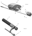
- Fig. 4A shows the motor drive 14 with a portion its housing removed.
- the surgical device 12 is shown separated from the motor drive 14.
- the motor drive 14 includes motors 24 and output elements 26, which in this embodiment take the form of pins or posts.
- each such output element 26 is in contact with, coupled to, or engaged with a corresponding input element 28 of the surgical device 12, or otherwise positioned to cause each input element 28 to move in accordance with its corresponding output element 26.
- the system may be set up so that the output elements 26 push the input elements 28 in response to motor activation, and/or so that the output elements pull the input elements 28.
- the embodiments described in this application focus primarily on “push” actuation, but it should be understood that these embodiments may be operated to include “pull” activation alone or in combination with push activation (as described in the '098 application).
- a surgical drape will extend between the motor drive 14 and the surgical device 12, and will extend between the input elements 28 and the output elements 26 to prevent the sterile surgical device 12 from losing sterility due to direct contact with the motor device.
- the motor drive 14 is configured to transfer motion from motors 24 to linear motion of the output elements 26.
- lead screw drives 30 are used for this purpose.
- each input element and its corresponding output element translates along a common axis, but others might use nonparallel axes, different parallel axes, or other types of offset axes.
- the interface between the output elements 26 and the input elements 28 places the output elements 26 and input elements 28 in a drive relationship, i.e. a relationship where linear translation of the output elements 26 directly causes linear translation of the input elements 28.
- This interface can take a variety of forms, each of which can be achieved without penetrating the material of the drape extending between the motor drive 14 and the surgical device 12 (even though the drape is positioned between the output elements 26 and input elements 28).
- the '098 application describes types of connections that can be used to allow input elements to capture, or be captured by, the corresponding output elements in a manner that does not compromise the drape extending between them, or to engage the input elements and their corresponding output elements.
- the input elements 28 and output elements 26 are not connected to one another, but simply push against one another (with the drape D remaining between them, as illustrated schematically in Fig. 7 ).
- the input and output elements might be so closely spaced that but for the drape they would be touching, or there might be a very small gap between them (with the drape disposed within that gap),
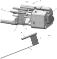
- the surgical device 12 includes a subsystem 38 that transfers the linear motion received from the output elements 26 of the motor drive 14 to the actuation elements 42 used for steering and/or articulation of the shaft of the surgical device 12, to any other actuation elements or assemblies used for opening and/or closing the jaws of an end effector on the distal end of the surgical device, or for axially rolling the end effector 23.
- rolling the end effector can be carried out by axially rolling the shaft 16 supporting the end effector, or by rolling the end effector relative to the shaft 16 by rotating an inner shaft (internal to the shaft 16) on which the end effector is mounted, or by other means.
- the linear motion received from the output elements 26 can be transferred to the actuation elements using pivotal, linear, or rotary means (including rotary means employing pulleys).
- each input element may be connected by a rigid link 80 to a corresponding actuation element 42 that extends within the shaft of the surgical device to an anchor point.
- the actuation element comprises hypotube, although other types of element can be used.
- the hypotube extends along the shaft's length to its anchor point within the surgical device shaft 16, or only a proximal portion of the actuation element may be made of hypotube with a distal portion being made of cable, wire, filament, etc.
- activation of the motor advances output element 26, which pushes input element 28 on the other side of the drape D.
- subsystem 38 of the illustrated embodiment includes the input elements 28, links 80, and actuation elements 42.
- the subsystem 38 is enclosed within a housing 44, with the input elements 28 exposed through openings 46 in the housing where they can be acted upon by the output elements 26 of the motor drive 14.
- Certain of the input elements 28 are each operatively associated with a different one of the actuation elements 42.
- the illustrated embodiment uses six actuation elements 42 for positioning of the end effector (e.g. 4 for movement of the actively bendable section in 2 degrees of freedom and 2 for movement of the deployment section in 1 degree of freedom).
- an additional actuation element (or, in other embodiments, two) may be used for opening and closing of the jaws as described below
- an embodiment of the surgical device 14 includes multiple sets of input elements 28.
- the input elements marked 28a operate the actuation elements whose actuation results in steering of the section 18a in two degrees of freedom.
- the two input elements marked 28b operate the actuation elements whose actuation results in steering of the deployment section 18b in one degree of freedom. Additional input elements 28b may be added if a second degree of freedom is needed at section 18b or elsewhere along the shaft.
- the input elements marked 28c, 28c' are associated with opening and closing of the jaws 23a. These input elements are part of an actuation assembly that is anchored to a proximal part of actuation element 42c as shown in Figs. 12 and 13 .
- the distal part of actuation element 42c is not shown in the drawings, but it is operatively connected to a clevis mechanism or other system connected to the jaws to actively open or close the jaws. Such mechanisms are well known in the art.
- a pivot member 40 within the housing 44 has a first end connected to input element 28c and a second end connected to the other input element 28c'.
- the pivot member 40 pivots on a center axis A, such that movement of one of the input elements 28c, 28c' in one direction causes the other input element to move in the opposite direction. For example, if one of the input elements 28c, 28c' is pressed towards the housing, the pivot member 40 pushes the other input element in a direction away from the housing 44.
- actuation element 42c is pulled to the right to open or close the jaws, and input 28c' moves in the opposite direction as pin 28c.
- the pivot member 40 pushes the input element 28c to the left, causing the actuation element 42c to move to the left, moving the jaws to the opposite configuration (from closed to open, or from open to closed).
- the input element is actively moved (e.g. pushed) by the corresponding motor driven drive element 26 to actively open or closed the jaws as described above, but a spring 28c is used to return the input element 28c to its biased position once the force imparted to it by the corresponding drive element 26 is released.
- control system used to control steering/articulation/deployment/jaw actuation and roll of the surgical device may receive feedback from load cells associated with each (or a plurality) of the output shafts 26 or drive pistons so as to generate signals representing the force applied to the output shafts 26 (or drive pistons), rotary encoders that determine the rotational positions of the motors, and/or other sensors positioned to detect linear displacement of components of the drive assembly. These are also schematically depicted in Fig. 7 . Signals from such sensors may be used, alone or in combination, by the control system to control movement and to thus optimize movement accuracy.
- Additional sensors may be positioned to sense the gap formed between output and input shafts 26, 28 or pistons, so as to detect whether the gap between corresponding input and output pistons is approaching a point where an input piston might become too far out of the range of the output piston to be controlled by the output piston.
- the input and output elements are positioned on opposite sides of the drape as shown in Fig. 7 .
- a motor is energized to advance an output element axially towards its corresponding input element, it pushes the input element towards the surgical device housing, causing the actuation element that is coupled to that input element to be pulled.
- a first motor might be energized to cause a corresponding first input element 28 to be pushed, resulting in the pulling of the associated first actuation element and causing the shaft to bend upwardly.
- a second motor is energized to cause another, second, input element 28 to be pushed, resulting in the pulling of a second actuation element anchored 180 degrees from the first actuation element, causing the shaft to bend downwardly.
- the first input element 28 moves outwardly as a result of the change in shape of the shaft 16, and the first motor is simultaneously energized to retract the first output element 26 in a corresponding amount.
- the motor drive is mounted, or mountable, to a support such as a support arm of the type used for surgical systems. Mounting may be direct or via an intermediate structure.
- the surgical device is mounted to the support, either directly or by way of a connection to the motor drive housing or to another structure between the surgical device and the support, so that the relative positions of the motor drive housing and the surgical device (e.g. the rigid proximal portion of the shaft 16, or the housing 44) remain fixed during the surgical procedure. This maintains the input and output shafts in the drive relationship through the procedure.
- a draping system for use in covering the motor device 14 might include features that accommodate the (push or pull) movement at the interface between the output elements 26 and input elements 28 without tearing the drape.
- Such features might include a plurality of pre-formed bellows or pockets, each positioned over one of the output elements 26, or they might include regions of material that are more elastic than the surrounding drape material.
- the drape can be provided without any such features if the elasticity of the drape is sufficient for relative movement of the output elements without perforating the drape.
- Alternative drape designs might include mechanical features attached to the drape to assist in the coupling of motion between output elements 26 and the input elements 28.
- This section describes various embodiments of linear to rotary conversion assemblies that may be used to convert linear motion transmitted by the motor drive across the sterile barrier/drape into rotary motion of a feature (be it a pulley, gear, cam, belt drive, etc.) where it can be used to drive roll of the surgical device or end effector.
- a feature be it a pulley, gear, cam, belt drive, etc.
- the rotary motion can also be continuous.
- the input elements identified as 28d are used to effect axial rolling of the end effector 23a. This may be achieved by rolling the shaft 16 itself, or, as illustrated, by rolling an internal shaft 17 that extends through the shaft 16 and that supports the end effector 23a.
- Input elements 28d are positioned on the surgical device to interface with a central rotary component 50.
- Rotary component 50 has a cam surface 52 formed of an externally located shelf as shown, or an internally cut cam path.
- the cam surface is a continuous curved surface encircling the shaft and having a first apex section and a second apex section, the first apex section being closer to the free end (the end extending in the direction of the end effector) than the second apex end.
- the first and second apex sections may be separated 180 degrees around the shaft as shown.
- the input elements 28d interface with the cam path/shelf such that when one input element translates forward, it causes rotation of the rotary component in one direction and forces translation of the other input elements 28d according to the shape of the cam surface 52.
- the direction of rotation can be reversed at any time.
- the motion can also be continuous if the sequence in which the pins are pushed by their corresponding drive elements 26 continues in the same direction for multiple rotations.
- the interface between the input elements 28d and the rotary component 50 may also include rolling members 54 as shown in Figs. 16 and 17 .
- the drive elements 26d for driving the roll motion extend from the motor drive housing in the circled region marked 26d.
- each of these drive elements 26d is in contact with, coupled to, or engaged with a corresponding input element 28d, or otherwise positioned to cause each input element 28d to move in accordance with its corresponding output element 26d.
- the motor drive 14 may include separate drive motors for each of the drive elements 26d, or gears may be used to allow two or more drive elements to be driven by a common motor.
- a motor may be configured to drive a rotary component similar to rotary component 50, and the drive elements 26d may be driven by the rotary component 50 in a manner similar to the way in which the input elements 28d drive the rotary component 50.
- Fig. 18 illustrates an alternative embodiment of an assembly for converting the linear input transferred from the drive elements 26 to the input elements 28 into rotation for rolling the surgical device or instrument tip.
- the rotation created can be continuous and reversible, using linear translation at the drape interface of only two pins/pistons.
- This concept differs from the above-described concept in that this concept is designed for a system where the drive elements both push and pull the input elements at the drape. Engagement between the drive elements and input elements may be carried out using overlapping mechanical features such as the hook features shown in Fig. 18 , or by using magnetic engagement to resist pulling apart, or other features, including those described in the '098.
- the linear inputs are connected to one another in a way that they are operating out of phase by 90 degrees. Their motion over time is depicted in the graph shown in Fig. 19 .
- one input element can be pushed or pulled while the other is at its indeterminate locations. This could be done with the reciprocating rack and pinion roll mechanism as described in connection with the third embodiment, or with a simple piston / crank mechanism.
- This embodiment is advantageous in that it makes use of two linear translating inputs through a drape to drive continuous and reversible roll. This would reduce the number of required motors for rolling.
- a third embodiment for converting the input linear translation into axial roll of the surgical instrument provides continuous, reversible rotation of a shaft. It is described in the context of a system where the output elements only push the input elements, but it can also be used in one where both pulling and pushing are used.
- the mechanism consists of a set of rack and pinions designed so that the rack reciprocates with a constant rotational input from the pinion. This motion can be reversed (i.e. the instantaneous direction of the rack) by reversing the pinion rotation direction.
- the pinion can also be driven by the racks so that one rack/pinion set can drive a matching rack pinion set.
- the advantage of this system over other methods of converting rotational motion to linear motion is that while the rack/pinion are engaged the mechanical advantage is constant. This will reduce (or eliminate) torque ripple in the rotating shaft.
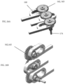
- Figs. 20A through 20F illustrate the various states described above.
- the pinion P is rotating counterclockwise and the rack R is traveling right to left.
- the third embodiment makes use of a rack and pinion in the instrument assembly for converting translational motion imparted to the rack into rotational motion of the pinion P, but modifies the rack and pinion configuration to overcome the difficulties described with reference to Figs. 20A - 20F .
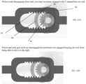
- a secondary cam/follower arrangement is added in order to keep the rack 60 and pinion 62 from binding if force is applied to the rack when it is switching directions.
- a cam/follower arrangement is shown in Figs. 21A , 22A and 22B .
- the arrangement can be a single cam/follower or a combination of two as shown. Referring to Fig.
- the rack 60 includes shaped bosses 64
- the pinion 62 includes pins 66 on an arcuate member 68 spaced apart from the teeth of the pinion 62.
- the pin 66 on the pinion gear engages the boss 64 on the rack and continues to push the rack after the pinion gear tooth has disengaged from the rack.
- Figs. 21A-21D show the exemplary pin/boss configuration in the same states as described with respect to Figs. 20A - 20F .
- the pinion is rotating counterclockwise and the rack is moving right to left.
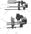
- Figs. 23A and 23B illustrates rack and pinion assemblies of the type described above arranged in a manner that will convert linear motion to rotary motion, and that will convert rotary motion to linear motion.
- Three rack/pinion assembles are arranged with their pinions mounted on a common shaft 70.
- Each pinion is at a different phase of its rotation, so that its corresponding rack is at a different point along its travel as best shown in Fig. 23A .
- each pinion is 120 degrees out of phase with the pinion of the adjacent rack(s).
- the shaft 70 is driven, with the rotation of the shaft 70 (and the pinions mounted to it) resulting in translation of the racks.
- the motor shaft used to drive the shaft 70 may be directly connected to or integral with the shaft 70, or its motion may be coupled to the shaft by gears.
- shaft 70 has a first gear 72.
- the motor drives a second shaft 74 (not shown in Figs. 23A and 23B , but see Fig. 24 ) that has a second gear 76 connected to it.
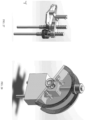
- Figs. 24(a) - (f) are a sequence of photos of a prototype system showing a sequence of motion of the pistons 78 of the three racks as the shaft 74 is manually rotated.
- the disclosed rack and pinion assemblies may be incorporated into both the drive side to convert rotary motion into linear motion for transfer across a sterile barrier such as a drape, and/or incorporated into the surgical device to convert linear motion received from across the sterile barrier into rotary motion that can be used to roll a part of the surgical device.
- a first assembly of the rack and pinion assemblies may be disposed in the surgical device housing (like housing 4 Fig. 8 ), with the pistons 78 of the racks replacing (and serving as) the input elements 28d of the surgical device and with shaft 74 being the device shaft 16 or an inner shaft that extends through the device shaft 16 and supports the end effector.
- a second assembly of the and pinion assemblies may be disposed in the motor drive, with a motor positioned to drive the shaft 70 either directly or via an intervening gear assembly as discussed above.
- rack and pinion assemblies into both the drive (motor drive) side and the driven (surgical device) side of the system is described, this is not a requirement.
- One embodiment might use the rack and pinion assemblies on the surgical device side, and an alternate assembly for translating the output elements on the drive system.
- each output element could be controlled by a separate motor.
- Another embodiment might use the rack and pinion assemblies on the motor drive side, and an alternate assembly on the surgical device side for receiving the linear motion and converting that linear motion to rotary motion used to effect instrument roll.
- Surgical drape D covering the motor drive assembly is positioned between the pistons of the systems 80, 80a, and the pistons of the assembly 80a (which are the surgical device's input members for the roll function) are brought into alignment with the pistons of the assembly 80 (which are the motor drive's output/drive members for the roll function), with the drape D sandwiched between them as shown in Fig. 26 .
- the pistons at the opposite ends of the racks are visible in the drawings, when the systems are incorporated into the motor drive assembly and the surgical device, these extra pistons need not be exposed.
- the motor drive is arranged to use three motors to linearly drive three output drive elements.
- the motors are configured so as to drive one output drive element (pin/piston) at a time.
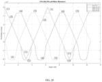
- Fig. 29 graphically depicts movement of the three output drive elements over time, and shows how they move out of phase from one another.
- the blue line (1) is the path that instrument pin #1 takes.
- the orange, yellow and purple lines (2), (3) and (4) are paths of motor-driven pins 1, 2, and 3 respectively. The paths are plotted versus the desired roll angle in radians (x-axis).
- Each motor pin uses the same function, but has a phase offset of 0, 120 and 240 degrees.
- the algorithm used to control the motors helps the system to avoid binding of the rack and pinion assemblies. It can be seen at the top of the wave that the motor pin is caused to stop moving at a distance of 1.3265 mm before the tip of the instrument pin, so as to allow the other components of the instrument roll mechanism to move the pin through its "turn around" zone. Additionally, the algorithm is constructed to insure that the instrument pin does not bind at the bottom of the wave.
- a 4th order polynomial (quartic) wave is added to the bottom to smoothly move the motor pin out of the way (its bottom position is 0.25 mm below the bottom of the instrument pin triangle wave.)
- the "disengagement" point where transition is made from the linear section to the polynomial curve is designed to overlap with the other pin's "flat” area by a few degrees to ensure that motor pin 3 is still stationary in its "flat” zone when motor pin 1 is moved away from the instrument pin. See the enlarged section of the chart shown in Fig. 30 , where a black line marks the point at which motor pin 1 is disengaged from the instrument pin.
- Figs. 23A - 25B show the pinions for the racks mounted to a common shaft (where each pinion is out of phase with the others to enable continuous rotation of the pinion shaft), in an alternative embodiment the pinions for each rack need not share a common shaft.
- Fig. 26 shows an embodiment in which each pinion 162 has its own axis (three pinions are shown.
- Each pinion 162 includes a spur gear 163 that moves integrally with the pinion. The pinions interface with one another via these spur gears. The manner in which the pinions 162 move within the racks 160 is similar to that described above.
- one of the pinions has a belt pulley our other output assembly coupled to its rotary motion such that the belt translates the rotation of the mechanism to the output shaft 174 for end effector rotation.
- shaft 174 is an input shaft that receives rotational motion from a motor, causing linear motion of the pistons extending from the pinions, whose reciprocating pistons may thus transmit the linear motion through the drape in the manner described above.
- FIG. 27 A fourth embodiment of an assembly for converting linear motion to rotary motion is shown in Fig. 27 .
- This configuration may be incorporated into the surgical device so that linear motion transferred from output elements of the motor drive (across the drape) is received and converted to rotary motion for rolling the surgical device shaft.
- the fourth embodiment uses two parallel lead screws, spaced apart such that the gear molded or cut into the lead screw nuts sync.
- the lead screws must be keyed so that they do not rotate.
- the lead screw When the lead screw is translated, it forces a rotation on its corresponding nut.
- the gear on that rotating nut forces rotation of the adjacent nut in the opposite direction.
- the rotation of the adjacent nut forces translation of the adjacent lead screw. Therefore, pushing one lead screw forward results in a reverse translation of the adj acent lead screw.
- the lead screw nut also has a timing belt pulley molded or machined into its outer diameter. Rotation of that nut drives a belt and another pulley to perform a desired action - in this case that action is instrument rotation.
- This system requires a balancing of torque and amount of rotation - which can be optimized based on the lead screw selection and gear train ratio on the belt drive.
- FIG. 28 A fifth embodiment of an assembly for converting linear motion to rotary motion is shown in Fig. 28 .
- This embodiment consists of two pistons, each engaging with two half-circle bevel gear "racks". Translating one piston forward tilts both bevel gears in one direction and translates the adjacent piston in an equal and opposite direction.
- the bevel gear racks are positioned to interface with a centrally located partial bevel gear. Gear tooth timing is crucial to this concept.
- the partial bevel gear only interfaces with one side of the rack at a time. When that rack is tilted in one direction or the other, the bevel gear is rotated in a direction corresponding with the rack tilt.
- the partial bevel gear is designed to jump to the adjacent track, such that tilting the racks back in the other direction actually results in the same direction of rotation on the bevel gear. This enables continuous rotation of the bevel gear where the partial bevel gear jumps from rack to rack at the end of piston stroke.
- a sixth embodiment is similar to the Fig. 16 embodiment. It can be operated with 3 or more pistons, equidistant (or not) and having parallel axes (or not). Each piston interfaces with an intermediate part that helps compensate for changes in angles in 2 directions.
- the part can be shaped like a "T", such that the primary leg of the "T” is rotationally connected to each piston. This allows the "T” part to rotate in an axis that is perpendicular to the axis of the piston.
- the top part of the "T” is rotationally connected to a wobble plate such that it can provide an additional degree of rotation during movement.
- the wobble plate toggles back and forth about a centrally located pivot. As it toggles back and forth, it interfaces with a centrally located shaft that has two diameters. The first diameter is the primary rotation axis and the shelf between the first and second diameters is angled relative to the shaft axis. The wobble plate interacts with the angled shelf such that pushing the wobble plate forces rotation on the centrally located shaft. The rotation can be reversed by reversing the direction of the piston movement.
- This concept is used in axial engine design.
- this embodiment could be modified to reduce the number of pistons to 2 pistons operating out of phase with one another (most efficient at 90 degrees out of phase).
- a seventh embodiment is a slider crank embodiment which makes use of two or more pistons, with the pistons operating out of phase with one another.
- the pistons interface with a rotary component through an intermediary linkage.
- the pistons may be oriented such that they have equal and opposite translation, or they could operate out of phase such that their translation is not equal and opposite.
- Each piston has a linkage connected at the top of the piston and the other end of each linkage is connected to a wheel (or crank). Translating a piston forward causes rotation of the wheel. Rotation of the wheel forces the adjacent piston to move as well.
- This concept can be operated with more than two pistons and, if the drive/output elements are configured to both push and pull the input elements, two pistons can be used to create continuous and reversible rotation on the wheel, assuming the two pistons operate out of phase with one another. This allows second piston to still generate rotation when the first piston is at its indeterminent locations
- the motor drives and surgical devices described herein are components of a surgical system that includes a user input device used by a surgeon to input instructions to the surgeon as to the desired movement or actuation of the surgical devices.
- the surgical system further includes a control system including one or more processors that receive signals from the user input devices and from sensors of the system, and that generate commands used to drive the motors to cause active bending, deployment, actuation, etc. of the surgical devices in accordance with the user's input.
- a display for displaying an image obtained from a scope within the body cavity e.g. a scope positioned and manipulated as described herein
- User input devices and control systems for robotic surgical systems, and laparoscopic/endoscopic image displays are known to those skilled in the art and so details of such systems are not provided herein.
- the hospital staff positions sterile drapes over the motor drive units, with the sterile drape material extending over the output elements.
- This step may be performed with the motor drives mounted to the support.
- Surgical devices are mounted to the system to position the input elements in a drive relationship with their corresponding output shafts, with the sterile drape disposed between the input elements and output elements.
- the surgeon operates the input devices while observing the procedure on the display.
- the control system operates the motors in response to user input so as to articulate, deploy, roll and actuate the surgical instruments in accordance with the user instructions.
- the motors used for driving may be replaced with other types of drivers including, without limitation, hydraulic or pneumatic drivers.
- Mechanical communication is possible by means of hydraulic actuation transmitted across the drape, without penetrating the drape.
- a robotic system includes a drive assembly/motor assembly 214 (which may be like motor drive assembly 14 described above) providing exposed output elements 226 such as the pins/pistons described above having linear displacement that can be precisely controlled.
- the motors 224 and the corresponding pins 226 can be arranged in a variety of patterns/arrays to create an overall configuration of pins/pistons, including the configurations described in the '098 as well as those shown in Figs. 31A - 31C .
- a surgical robotic system of this type may provide an open platform that can be used for various types of instruments having functions (instrument roll, articulation in one or more degrees of freedom, jaw actuation, etc) that are actuated using linear input, without requiring that particular drive pins 226 be used to actuate a particular type of function.
- a particular drive pin might actuate one function (e.g. shaft articulation or bending) when one surgical device is mounted to the motor drive assembly, yet actuate a different function (e.g. instrument roll) when a different surgical device is mounted to that motor drive assembly.
- This allows creation of an array or pattern of any number of motors against which instruments can be assembled over a sterile drape.
- the motor array and corresponding pin arrangement may have any number of different arrangements.
- the drive pins 226 are arranged in a 2x6 arrangement as shown in Figs. 32A - 32E . This may achieved by arranging the motors 224 in the rectangular configuration shown in Fig. 31C .
- the drive system allows a single drive array to used with a variety of interchangeable instruments without requiring that particular pins of the drive array be dedicated to just a single surgical device function.
- each such drive pins may be capable of moving from 0mm to 20mm with the same precision and load.
- a variety of instruments can be designed around these inputs to enable any number of feature sets.
- Fig. 32A the pattern of Fig. 32A , below, read from left to right, describes an instrument that has six pins dedicated to articulation (pins 226a), three pins dedicated to instrument roll (pins 226b), and two pins (226c) dedicated to jaw actuation (green). The remaining pin 226d is un-utilized for this particular instrument.
- the first 6 pins 226a are dedicated to articulation
- the next column of pins 226b are used for instrument roll
- the two columns of pins 226c on the right may be used to articulate the surgical instrument's end effector or actuate a wrist mechanism.
- the first column's two pins 226a might enable instrument roll, while the next six pins 226b allow for articulation, and the final pins 226c are not utilized for that particular instrument.
- Still another example could be a suction/irrigation application where more than one surgical device may be positioned at a single motor array.
- the six pins 226a of the first three columns may enable articulation as before, the pins 226b of the next two columns are un-used, the last two pins 226c (the far right column) are used to operate a valve mechanism to switch between three positions: (1) Off, (2) Suction Enabled and (3) Irrigation flow.
- the valve mechanism may be removeably attached to the articulation device, the articulation device having a channel through which fluid may pass in either direction.
- Fig. 32E arrangement could be used for an instrument that has eight actuators (corresponding to pins 226a) for tip positioning, two actuators (corresponding to pins 226b) for performing roll and two actuators (corresponding to pins 226c) for performing jaw actuation.
- an electromechanical surgical system can be provided that includes a uniform motor array, in which each driver is configured to have the same range of travel, precision, speed and force. This enables instruments to be designed with any degree of freedom cascade desired
- the surgical device 212 is a robotically-controlled, steerable open lumen instrument, which may have functions (e.g. bending/articulation) that can be driven as described in the '098 using a first subset of the available pins of the drive assembly, and to which other auxiliary devices 213 can dock and have their functions actuated by the drive assembly 214 of the robotic system via a second subset of the pins of the drive assembly.
- both the surgical device 2121 and auxiliary device can be driven or actuated via the robotic user interface, by way of the pin actuators on a common drive assembly.
- FIGs. 33A and 33B An embodiment shown in Figs. 33A and 33B includes a surgical device 212 that includes an instrument housing and shaft with a steerable distal end.
- Input pins 224a of the surgical device receive linear motion from output pins 226a of the drive assembly 214 to control this steering function, as described in the '098 application.
- the instrument shaft is an open lumen that can be used to pass fluids or catheters, surgical tools or materials, directed to and from a desired location in the surgical site.
- the instrument housing 244 and/or drive assembly frame enables docking of the auxiliary devices 213 so they can be supported during use.
- Drive pins 226b on the drive assembly 214 deliver motion to drive pins 224b on the auxiliary instrument in order to actuate its functions.
- the auxiliary instrument 213 docked to the steerable open lumen instrument may be a suction irrigation implement fluidly coupled to the open lumen so that the suction irrigator can administer fluid through the open lumen of the open lumen, or be used to evacuate fluid from the surgical site through the open lumen.
- Drive pins 226b of the drive assembly drive pins 224b of the suction irrigation implement, which are operatively associated with the function of the valve system within the suction irrigation implement 213.
- movement of pins 224b actuates the valve system to selectively deliver/terminate administration of irrigation fluid and/or suction based on input given to the robotic system by the surgeon or the surgical staff (e.g. using a surgeon input devices at the surgeon console).
- auxiliary device 213 is a biopsy tool that is passed down the shaft of the open lumen instrument. Movement of the biopsy jaws 213a is actuated by delivering motion from the drive pins 226b to the inputs 224b as previously described, while steering of the shaft of instrument 212 is actuated by a different subset of the drive pins as discussed above.
- the auxiliary device may be a diagnostic device, such as a multispectral fiber-optic tool that can be being passed down the open lumen of the instrument and steered into place (through motion of the steerable surgical device) where the fiber-optic tool can be used to perform a tissue analysis.
- a diagnostic device such as a multispectral fiber-optic tool that can be being passed down the open lumen of the instrument and steered into place (through motion of the steerable surgical device) where the fiber-optic tool can be used to perform a tissue analysis.
- the open platform robotic surgical system described here can be used to allow disposable surgical instruments to attach to a re-usable or limited-life steerable instrument in a way that the disposable instrument can be steered about the abdomen and actuated to perform specific surgical tasks.
Landscapes
- Health & Medical Sciences (AREA)
- Surgery (AREA)
- Life Sciences & Earth Sciences (AREA)
- Engineering & Computer Science (AREA)
- Biomedical Technology (AREA)
- Heart & Thoracic Surgery (AREA)
- Medical Informatics (AREA)
- Molecular Biology (AREA)
- Animal Behavior & Ethology (AREA)
- General Health & Medical Sciences (AREA)
- Public Health (AREA)
- Veterinary Medicine (AREA)
- Nuclear Medicine, Radiotherapy & Molecular Imaging (AREA)
- Robotics (AREA)
- Manipulator (AREA)
- Surgical Instruments (AREA)
Claims (14)
- Système chirurgical comprenant :une unité de commande (14) sur un support (82), l'unité de commande (14) comprenant une pluralité d'actionneurs (24) et une pluralité d'éléments de sortie (26d), chaque actionneur étant opérationnel pour déplacer linéairement l'un correspondant des éléments de sortie (26d) ;dispositif chirurgical (12) comprenantun arbre de dispositif allongé (16),un sous-système d'entrée porté à l'extrémité proximale de l'arbre de dispositif allongé (16),le sous-système d'entrée comprenant une pluralité d'éléments d'entrée (28d) associés chacun de manière opérationnelle à un ensemble de conversion de linéaire à rotatif, chaque élément d'entrée (28d) étant linéairement déplaçable ;où le dispositif chirurgical (12) est monté de manière détachable par rapport au support (82) pour positionner chaque élément de sortie (26d) dans une relation d'entraînement avec un élément d'entrée correspondant (28d) ; etdans lequel le fonctionnement d'un actionneur (24) déplace linéairement un élément de sortie (26d), causant un déplacement linéaire d'un élément d'entrée correspondant (28d) et la rotation axiale de l'arbre de dispositif allongé (16),caractérisé en ce que l'ensemble de conversion comprend un arbre (50) ayant une surface de came (52), chacun des éléments d'entrée (28d) étant couplé à l'arbre (50) de sorte que le déplacement de chaque élément d'entrée (28d) contre la surface de came cause la rotation de l'arbre (50), l'arbre (50) et l'arbre de dispositif allongé (16) étant arrangés de sorte que la rotation de l'arbre (50) résulte en la rotation de l'arbre de dispositif allongé (16).
- Système chirurgical selon la revendication 1, dans lequel chaque élément de sortie (26d) et son élément d'entrée correspondant (28d) est déplaçable linéairement le long d'un axe commun.
- Système chirurgical selon la revendication 1, dans lequel chaque élément d'entrée (28d) est engagé mécaniquement avec son élément de sortie (26d) correspondant.
- Système chirurgical selon la revendication 1, dans lequel chaque élément d'entrée (28d) est magnétiquement en interface avec son élément de sortie correspondant (26d).
- Système chirurgical selon la revendication 1, dans lequel l'arbre de dispositif allongé (16) est un arbre externe ou un arbre interne s'étendant à travers un arbre externe.
- Système chirurgical selon la revendication 1, dans lequel chaque élément d'entrée (28d) n'est pas attaché mécaniquement à son élément de sortie (26d) correspondant.
- Système chirurgical selon la revendication 1, comprenant en outre un drap (D) stérile positionnable entre les éléments d'entrée (28d) et les éléments de sortie (26d).
- Système chirurgical selon la revendication 7, dans lequel les éléments d'entrée et de sortie ne pénètrent pas le drap (D).
- Système chirurgical selon la revendication 1, dans lequel la surface de came est définie par un collier sur l'arbre (50).
- Système chirurgical selon la revendication 1, dans lequel la surface de came est définie par une rainure dans l'arbre (50).
- Système chirurgical selon la revendication 1, dans lequel l'arbre (50) a une première extrémité, et dans lequel la surface de came (52) est une surface courbée continue encerclant l'arbre (50) et ayant au moins deux sections de sommet, comprenant une première section de sommet et une deuxième section de sommet, la première section de sommet étant plus proche de la première extrémité que la deuxième section de sommet.
- Système chirurgical selon la revendication 11, dans lequel la première et la deuxième section de sommet sont séparées de 180 degrés autour de l'arbre.
- Système chirurgical comprenant :une unité de commande (14) sur un support (82), l'unité de commande (14) comprenant une pluralité d'actionneurs (24) et une pluralité d'éléments de sortie (26d), chaque actionneur (24) étant opérationnel pour déplacer linéairement l'un correspondant des éléments de sortie (26d) ;dispositif chirurgical (12) comprenantun arbre de dispositif allongé (74),un sous-système d'entrée porté à l'extrémité proximale de l'arbre de dispositif allongé (74), le sous-système d'entrée comprenant une pluralité d'éléments d'entrée (78) associés chacun de manière opérationnelle à un ensemble de conversion de linéaire à rotatif, chaque élément d'entrée (78) étant linéairement déplaçable ;où le dispositif chirurgical (12) est monté de manière détachable par rapport au support (82) pour positionner chaque élément de sortie (26d) dans une relation d'entraînement avec un élément d'entrée correspondant (78) ; etdans lequel le fonctionnement d'un actionneur (24) déplace linéairement un élément de sortie (26d), causant un déplacement linéaire d'un élément d'entrée correspondant (78) et la rotation axiale de l'arbre de dispositif allongé (74),dans lequel l'élément de conversion comprend un arbre et une pluralité d'ensembles d'engrenage à crémaillère, chaque ensemble d'engrenage à crémaillère comprenantun engrenage (62) monté à l'arbre (70), etune crémaillère (60) qui est engagée avec l'engrenage (62) de sorte que le déplacement linéaire de la crémaillère (60) produit la rotation de l'engrenage (62) et ceci comprend l'un des éléments d'entrée (78),dans lequel chaque crémaillère (60) est positionnée par rapport à son engrenage (62) correspondant de sorte que les crémaillères (60) se déplacent linéairement par rapport à l'arbre (70), le mouvement linéaire de chaque crémaillère (60) étant déphasé de celui des autres crémaillères (60) de sorte que le mouvement collectif des crémaillères (60) cause la rotation continue de l'arbre (70), et dans lequel l'arbre (70) et l'arbre de dispositif allongé (74) sont arrangés de sorte que la rotation de l'arbre résulte en la rotation de l'arbre de dispositif allongé (74),caractérisé en ce que chaque ensemble d'engrenage à crémaillère comprend en outre une surface de came (64) disposée sur la crémaillère (60) et un galet suiveur (68) comprenant une goupille (66) portée par l'engrenage (62), la surface de came (64) et le galet suiveur (68) étant façonnés de sorte que lorsque les dents de la crémaillère (60) et de l'engrenage (62) se désengagent durant la course linéaire de la crémaillère (60) par rapport à l'engrenage (62) dans une première direction, le contact entre la came (64) et la goupille (66) sur le galet suiveur (68) fait que le mouvement relatif de la crémaillère (60) et de l'engrenage (62) continue dans la première direction malgré le désengagement des dents.
- Système chirurgical selon la revendication 13, comprenant en outre un drap stérile (D) positionnable entre les éléments d'entrée (78) et les éléments de sortie (26d), dans lequel les éléments d'entrée et de sortie ne pénètrent pas le drap (D).
Applications Claiming Priority (4)
| Application Number | Priority Date | Filing Date | Title |
|---|---|---|---|
| US201662322539P | 2016-04-14 | 2016-04-14 | |
| US201662322585P | 2016-04-14 | 2016-04-14 | |
| US201662322529P | 2016-04-14 | 2016-04-14 | |
| PCT/US2017/027818 WO2017181153A1 (fr) | 2016-04-14 | 2017-04-14 | Système chirurgical électromécanique comprenant un rouleau d'instrument entraîné linéairement |
Publications (3)
| Publication Number | Publication Date |
|---|---|
| EP3442432A1 EP3442432A1 (fr) | 2019-02-20 |
| EP3442432A4 EP3442432A4 (fr) | 2019-12-11 |
| EP3442432B1 true EP3442432B1 (fr) | 2024-06-19 |
Family
ID=60041993
Family Applications (1)
| Application Number | Title | Priority Date | Filing Date |
|---|---|---|---|
| EP17783340.7A Active EP3442432B1 (fr) | 2016-04-14 | 2017-04-14 | Système chirurgical électromécanique comprenant un rouleau d'instrument entraîné linéairement |
Country Status (5)
| Country | Link |
|---|---|
| US (4) | US11497481B2 (fr) |
| EP (1) | EP3442432B1 (fr) |
| KR (1) | KR102429815B1 (fr) |
| CN (1) | CN110087558B (fr) |
| WO (1) | WO2017181153A1 (fr) |
Families Citing this family (34)
| Publication number | Priority date | Publication date | Assignee | Title |
|---|---|---|---|---|
| WO2018144654A1 (fr) | 2017-01-31 | 2018-08-09 | Transenterix Surgical, Inc. | Système d'entraînement d'instrument hydraulique pour chirurgie mini-invasive |
| AU2019369303B2 (en) * | 2018-10-30 | 2021-12-23 | Covidien Lp | Binding and non-binding articulation limits for robotic surgical systems |
| WO2020186074A1 (fr) * | 2019-03-14 | 2020-09-17 | Worcester Polytechnic Institute | Sonde chirurgicale à articulation souple |
| US10952800B2 (en) * | 2019-04-26 | 2021-03-23 | Covidien Lp | Articulation assembly for a surgical instrument such as for use in a robotic surgical system and methods of assembling the same |
| US11751959B2 (en) * | 2019-07-16 | 2023-09-12 | Asensus Surgical Us, Inc. | Dynamic scaling for a robotic surgical system |
| CN110703426A (zh) * | 2019-11-14 | 2020-01-17 | 桂林电子科技大学 | 一种工业探视镜 |
| US11969280B2 (en) | 2020-01-07 | 2024-04-30 | Cleerly, Inc. | Systems, methods, and devices for medical image analysis, diagnosis, risk stratification, decision making and/or disease tracking |
| US20220392065A1 (en) | 2020-01-07 | 2022-12-08 | Cleerly, Inc. | Systems, methods, and devices for medical image analysis, diagnosis, risk stratification, decision making and/or disease tracking |
| CA3162872A1 (fr) | 2020-01-07 | 2021-07-15 | James K. MIN | Systemes, procedes et dispositifs d'analyse d'images medicales, de diagnostic, de stratification de risque, de prise de decision et/ou de suivi de maladie |
| EP4259259A4 (fr) * | 2021-01-14 | 2024-09-18 | Corindus, Inc. | Système d'entraînement robotique pour un système d'intervention basé sur un cathéter |
| CN113081086B (zh) * | 2021-04-27 | 2022-04-01 | 极限人工智能有限公司 | 一种手术辅助器械 |
| US12564458B2 (en) | 2022-08-01 | 2026-03-03 | Imperative Care, Inc. | Method of robotically driving a multi catheter assembly above the aortic arch |
| US12564414B2 (en) | 2022-08-01 | 2026-03-03 | Imperative Care, Inc. | Method of supra-aortic access for a neurovascular procedure |
| US12446979B2 (en) | 2022-08-01 | 2025-10-21 | Imperative Care, Inc. | Method of performing a multi catheter robotic neurovascular procedure |
| US12558175B2 (en) | 2021-08-12 | 2026-02-24 | Imperative Care, Inc. | Multi catheter method of performing a robotic neurovascular procedure |
| US12419703B2 (en) | 2022-08-01 | 2025-09-23 | Imperative Care, Inc. | Robotic drive system for achieving supra-aortic access |
| US12440289B2 (en) | 2022-08-01 | 2025-10-14 | Imperative Care, Inc. | Method of priming an interventional device assembly |
| US12447317B2 (en) | 2022-08-01 | 2025-10-21 | Imperative Care, Inc. | Method of priming concentrically stacked interventional devices |
| JP7840987B2 (ja) | 2021-10-05 | 2026-04-06 | シーメンス ヘルシニアーズ エンドバスキュラー ロボティクス インコーポレイテッド | 細長い医療デバイスのロボット制御 |
| CN114391899B (zh) * | 2022-02-24 | 2023-07-14 | 上海微创医疗机器人(集团)股份有限公司 | 手术器械传动机构、手术器械传动装置及手术器械 |
| US20250217981A1 (en) | 2022-03-10 | 2025-07-03 | Cleerly, Inc. | Systems, methods, and devices for image-based plaque analysis and risk determination |
| US20250143657A1 (en) | 2022-03-10 | 2025-05-08 | Cleerly, Inc. | Systems, devices, and methods for non-invasive image-based plaque analysis and risk determination |
| US12406365B2 (en) | 2022-03-10 | 2025-09-02 | Cleerly, Inc. | Systems, devices, and methods for non-invasive image-based plaque analysis and risk determination |
| US12440180B2 (en) | 2022-03-10 | 2025-10-14 | Cleerly, Inc. | Systems, devices, and methods for non-invasive image-based plaque analysis and risk determination |
| DE102022107857A1 (de) * | 2022-04-01 | 2023-10-05 | Tuebingen Scientific Medical Gmbh | Pneumatische Antriebsvorrichtung zur translatorischen und/oder rotatorischenBewegung |
| US20240041480A1 (en) | 2022-08-02 | 2024-02-08 | Imperative Care, Inc. | Multi catheter system with integrated fluidics management |
| CN120529877A (zh) | 2022-12-01 | 2025-08-22 | 因普瑞缇夫护理公司 | 用于机器人化导管驱动系统的防屈曲装置 |
| CN120529878A (zh) | 2022-12-01 | 2025-08-22 | 因普瑞缇夫护理公司 | 伸缩驱动台及使用方法 |
| JP2026500622A (ja) | 2022-12-01 | 2026-01-08 | インペラティブ ケア インコーポレイテッド | ロボットカテーテル駆動システムのためのコントローラ |
| WO2024238831A2 (fr) | 2023-05-17 | 2024-11-21 | Imperative Care, Inc. | Système de commande fluidique pour pile de cathéters multiples |
| WO2024249670A2 (fr) | 2023-05-31 | 2024-12-05 | Imperative Care, Inc. | Couplage magnétique à travers une barrière de champ stérile |
| CN116807543A (zh) * | 2023-07-18 | 2023-09-29 | 北京派尔特医疗科技股份有限公司 | 一种电动吻合器 |
| USD1119865S1 (en) | 2023-11-30 | 2026-03-24 | Imperative Care, Inc. | Controller |
| WO2025253297A1 (fr) * | 2024-06-04 | 2025-12-11 | Multi-Scale Medical Robotics Center Limited | Mécanisme d'actionnement pour manipulateur robotique flexible |
Family Cites Families (52)
| Publication number | Priority date | Publication date | Assignee | Title |
|---|---|---|---|---|
| US6436107B1 (en) | 1996-02-20 | 2002-08-20 | Computer Motion, Inc. | Method and apparatus for performing minimally invasive surgical procedures |
| US7699855B2 (en) | 1996-12-12 | 2010-04-20 | Intuitive Surgical Operations, Inc. | Sterile surgical adaptor |
| US8206406B2 (en) | 1996-12-12 | 2012-06-26 | Intuitive Surgical Operations, Inc. | Disposable sterile surgical adaptor |
| US7297142B2 (en) * | 1998-02-24 | 2007-11-20 | Hansen Medical, Inc. | Interchangeable surgical instrument |
| JP4542710B2 (ja) | 1998-11-23 | 2010-09-15 | マイクロデクステラティー・システムズ・インコーポレーテッド | 外科用マニプレータ |
| US20030135204A1 (en) | 2001-02-15 | 2003-07-17 | Endo Via Medical, Inc. | Robotically controlled medical instrument with a flexible section |
| EP1232836A1 (fr) | 2001-02-19 | 2002-08-21 | Manufactures d'Outils Dumont S.A. | Porte-brucelles |
| US8398634B2 (en) | 2002-04-18 | 2013-03-19 | Intuitive Surgical Operations, Inc. | Wristed robotic surgical tool for pluggable end-effectors |
| US7824401B2 (en) * | 2004-10-08 | 2010-11-02 | Intuitive Surgical Operations, Inc. | Robotic tool with wristed monopolar electrosurgical end effectors |
| EP2359768B1 (fr) | 2002-12-06 | 2018-10-03 | Intuitive Surgical Operations, Inc. | Poignee flexible pour outil chirurgical |
| US8806973B2 (en) * | 2009-12-02 | 2014-08-19 | Covidien Lp | Adapters for use between surgical handle assembly and surgical end effector |
| JP2005131173A (ja) * | 2003-10-31 | 2005-05-26 | Olympus Corp | 内視鏡用外付けチャンネル |
| US20060196299A1 (en) | 2005-01-27 | 2006-09-07 | John Taboada | Seven Axis End Effector Articulating Mechanism |
| US20070135803A1 (en) | 2005-09-14 | 2007-06-14 | Amir Belson | Methods and apparatus for performing transluminal and other procedures |
| EP1815949A1 (fr) | 2006-02-03 | 2007-08-08 | The European Atomic Energy Community (EURATOM), represented by the European Commission | Système médical robotisé comprenant un bras manipulateur de type à coordonées cylindriques |
| EP1815950A1 (fr) | 2006-02-03 | 2007-08-08 | The European Atomic Energy Community (EURATOM), represented by the European Commission | Dispositif chirurgical robotique pour effectuer des techniques opératoires minimalement invasive |
| WO2007143859A1 (fr) | 2006-06-14 | 2007-12-21 | Macdonald Dettwiler & Associates Inc. | Manipulateur chirurgical avec mécanismes d'entraînement par poulies à angle droit |
| EP1915963A1 (fr) | 2006-10-25 | 2008-04-30 | The European Atomic Energy Community (EURATOM), represented by the European Commission | Estimation de la force pour un systeme d'intervention chirurgicale robotisée à effraction minimale |
| WO2008120753A1 (fr) | 2007-03-30 | 2008-10-09 | Osaka University | Dispositif manipulateur médical et actionneur approprié pour celui-ci |
| DE102008005901B4 (de) | 2008-01-24 | 2018-08-09 | Deutsches Zentrum für Luft- und Raumfahrt e.V. | Sterilbarriere für einen chirurgischen Roboter mit Drehmomentsensoren |
| US7886743B2 (en) | 2008-03-31 | 2011-02-15 | Intuitive Surgical Operations, Inc. | Sterile drape interface for robotic surgical instrument |
| US8333755B2 (en) | 2008-03-31 | 2012-12-18 | Intuitive Surgical Operations, Inc. | Coupler to transfer controller motion from a robotic manipulator to an attached instrument |
| JP4900439B2 (ja) | 2008-10-01 | 2012-03-21 | 三菱電機株式会社 | 面状光源装置およびこれを用いた表示装置 |
| US9060748B2 (en) | 2009-03-18 | 2015-06-23 | Smith & Nephew, Inc. | Soft tissue manipulator assembly |
| US20100324551A1 (en) * | 2009-06-18 | 2010-12-23 | Tyco Healthcare Group Lp | Laparoscopic shaft articulation by means of a rotating collar |
| US9517027B2 (en) * | 2009-07-10 | 2016-12-13 | Facet Techonologies, Llc | Advancement mechanism for cartridge-based devices |
| IT1401669B1 (it) | 2010-04-07 | 2013-08-02 | Sofar Spa | Sistema di chirurgia robotizzata con controllo perfezionato. |
| US20110282357A1 (en) | 2010-05-14 | 2011-11-17 | Intuitive Surgical Operations, Inc. | Surgical system architecture |
| US8603077B2 (en) | 2010-05-14 | 2013-12-10 | Intuitive Surgical Operations, Inc. | Force transmission for robotic surgical instrument |
| US9301753B2 (en) * | 2010-09-30 | 2016-04-05 | Ethicon Endo-Surgery, Llc | Expandable tissue thickness compensator |
| KR101993815B1 (ko) * | 2010-11-15 | 2019-06-27 | 인튜어티브 서지컬 오퍼레이션즈 인코포레이티드 | 수술 기구에서 기구 샤프트 감김과 단부 작동기 작동의 해제 |
| GB2487199A (en) * | 2011-01-11 | 2012-07-18 | Creo Medical Ltd | Electrosurgical device with fluid conduit |
| EP3666162B1 (fr) | 2011-10-21 | 2025-01-22 | Viking Systems, Inc. | Endoscope stéréoscopique électronique orientable |
| US8912746B2 (en) * | 2011-10-26 | 2014-12-16 | Intuitive Surgical Operations, Inc. | Surgical instrument motor pack latch |
| WO2013074970A1 (fr) * | 2011-11-16 | 2013-05-23 | Vanderbilt University | Dispositif mobile pour utilisation dans des environnements magnétiquement sensibles |
| BR112014019193B1 (pt) | 2012-02-02 | 2021-06-15 | Great Belief International Limited | Sistema cirúrgico motorizado |
| EP2881063B1 (fr) | 2012-04-27 | 2019-06-26 | KUKA Deutschland GmbH | Système de robot chirurgical |
| CN104546139B (zh) | 2012-04-27 | 2017-07-28 | 库卡实验仪器有限公司 | 机器人手术系统和手术器械 |
| US9125662B2 (en) * | 2012-06-28 | 2015-09-08 | Ethicon Endo-Surgery, Inc. | Multi-axis articulating and rotating surgical tools |
| US9393037B2 (en) * | 2012-06-29 | 2016-07-19 | Ethicon Endo-Surgery, Llc | Surgical instruments with articulating shafts |
| EP2881073B1 (fr) * | 2012-07-03 | 2019-07-24 | KUKA Deutschland GmbH | Système d'instrument chirurgical et de transmission pour un instrument chirurgical, notamment robotisé et instrument chirurgical |
| DE102013007761A1 (de) * | 2013-05-06 | 2014-11-06 | Kuka Laboratories Gmbh | Chirurgisches Instrument |
| US20140017665A1 (en) | 2012-07-10 | 2014-01-16 | Lifeline Scientific, Inc. | Organ transporter with oxygen generation |
| CN113397655A (zh) | 2012-11-14 | 2021-09-17 | 直观外科手术操作公司 | 用于双控制手术器械的系统和方法 |
| EP2958507B1 (fr) | 2013-02-20 | 2017-09-27 | Olympus Corporation | Manipulateur médical |
| CN105026116B (zh) | 2013-02-27 | 2017-03-08 | 奥林巴斯株式会社 | 机械手 |
| ITMI20130516A1 (it) | 2013-04-05 | 2014-10-06 | Sofar Spa | Sistema chirurgico con teli sterili |
| US9649110B2 (en) * | 2013-04-16 | 2017-05-16 | Ethicon Llc | Surgical instrument comprising a closing drive and a firing drive operated from the same rotatable output |
| JP2015173731A (ja) | 2014-03-13 | 2015-10-05 | オムロン株式会社 | 画像登録装置、および遊技媒体振分システム |
| DE102014205036A1 (de) | 2014-03-18 | 2015-09-24 | Richard Wolf Gmbh | Endoskopisches Instrument zum Anschluss an einen Operationsroboter |
| WO2016057989A2 (fr) | 2014-10-10 | 2016-04-14 | Transenterix, Inc. | Système chirurgical électromécanique |
| CA3286214A1 (en) * | 2015-07-17 | 2025-11-29 | Deka Products Limited Partnership | Robotic surgery system, method, and apparatus |
-
2017
- 2017-04-14 KR KR1020187032548A patent/KR102429815B1/ko active Active
- 2017-04-14 CN CN201780036972.8A patent/CN110087558B/zh active Active
- 2017-04-14 WO PCT/US2017/027818 patent/WO2017181153A1/fr not_active Ceased
- 2017-04-14 EP EP17783340.7A patent/EP3442432B1/fr active Active
-
2018
- 2018-10-15 US US16/160,960 patent/US11497481B2/en active Active
-
2020
- 2020-10-06 US US17/063,974 patent/US12133698B2/en active Active
- 2020-10-06 US US17/064,039 patent/US12274518B2/en active Active
-
2021
- 2021-12-31 US US17/566,973 patent/US20220117683A1/en active Pending
Also Published As
| Publication number | Publication date |
|---|---|
| US20220008146A1 (en) | 2022-01-13 |
| EP3442432A4 (fr) | 2019-12-11 |
| EP3442432A1 (fr) | 2019-02-20 |
| US11497481B2 (en) | 2022-11-15 |
| US12133698B2 (en) | 2024-11-05 |
| US20210093311A1 (en) | 2021-04-01 |
| CN110087558A (zh) | 2019-08-02 |
| US20220117683A1 (en) | 2022-04-21 |
| WO2017181153A1 (fr) | 2017-10-19 |
| US12274518B2 (en) | 2025-04-15 |
| KR20180134957A (ko) | 2018-12-19 |
| CN110087558B (zh) | 2022-12-23 |
| KR102429815B1 (ko) | 2022-08-08 |
| US20210085304A1 (en) | 2021-03-25 |
Similar Documents
| Publication | Publication Date | Title |
|---|---|---|
| US11497481B2 (en) | Electromechanical surgical system including linearly driven instrument roll | |
| US12295688B2 (en) | Translational instrument interface for surgical robot and surgical robot systems comprising the same | |
| EP3203924B1 (fr) | Système chirurgical électromécanique | |
| US12256955B2 (en) | Surgical devices and systems with rotating end effector assemblies having an ultrasonic blade | |
| EP3616640B1 (fr) | Mécanisme de transmission de force pour instrument chirurgical et systèmes | |
| CN113811257B (zh) | 用于致动张力带的带有长度守恒机构的医疗工具 | |
| CN111513851B (zh) | 机器人手术系统、器械驱动单元以及驱动组件 | |
| US8333780B1 (en) | Surgical tool and method of operation | |
| JP2022002759A (ja) | 改善された可動域を有する機械的なリストジョイント、関連装置、及び方法 | |
| CN108025445A (zh) | 机器人臂及机器人手术系统 | |
| US20250325338A1 (en) | Low-friction medical tools having roller-assisted tension members | |
| JP2021514220A (ja) | 手術ロボットシステム | |
| JP2015093190A (ja) | 手首機構を有する医療デバイスアダプター | |
| CN120189236A (zh) | 手术工具及手术机器人系统 | |
| WO2024006890A1 (fr) | Élément mâchoire d'effecteur d'extrémité d'instrument et dispositifs, systèmes et procédés associés | |
| US12279840B2 (en) | Selectable jaw closure of a robotic surgical system | |
| CN120344206A (zh) | 包括具有可关节运动的末端执行器的手术器械的机器人手术组件 | |
| WO2022175641A1 (fr) | Mécanisme d'actionnement de mâchoire |
Legal Events
| Date | Code | Title | Description |
|---|---|---|---|
| STAA | Information on the status of an ep patent application or granted ep patent |
Free format text: STATUS: THE INTERNATIONAL PUBLICATION HAS BEEN MADE |
|
| PUAI | Public reference made under article 153(3) epc to a published international application that has entered the european phase |
Free format text: ORIGINAL CODE: 0009012 |
|
| STAA | Information on the status of an ep patent application or granted ep patent |
Free format text: STATUS: REQUEST FOR EXAMINATION WAS MADE |
|
| 17P | Request for examination filed |
Effective date: 20181112 |
|
| AK | Designated contracting states |
Kind code of ref document: A1 Designated state(s): AL AT BE BG CH CY CZ DE DK EE ES FI FR GB GR HR HU IE IS IT LI LT LU LV MC MK MT NL NO PL PT RO RS SE SI SK SM TR |
|
| AX | Request for extension of the european patent |
Extension state: BA ME |
|
| DAV | Request for validation of the european patent (deleted) | ||
| DAX | Request for extension of the european patent (deleted) | ||
| REG | Reference to a national code |
Ref country code: DE Ref legal event code: R079 Free format text: PREVIOUS MAIN CLASS: A61B0017000000 Ipc: A61B0034300000 |
|
| A4 | Supplementary search report drawn up and despatched |
Effective date: 20191113 |
|
| RIC1 | Information provided on ipc code assigned before grant |
Ipc: A61B 17/00 20060101ALI20191107BHEP Ipc: A61B 46/10 20160101ALN20191107BHEP Ipc: A61B 34/30 20160101AFI20191107BHEP |
|
| RAP3 | Party data changed (applicant data changed or rights of an application transferred) |
Owner name: ASENSUS SURGICAL US, INC. |
|
| P01 | Opt-out of the competence of the unified patent court (upc) registered |
Effective date: 20230509 |
|
| GRAP | Despatch of communication of intention to grant a patent |
Free format text: ORIGINAL CODE: EPIDOSNIGR1 |
|
| STAA | Information on the status of an ep patent application or granted ep patent |
Free format text: STATUS: GRANT OF PATENT IS INTENDED |
|
| RIC1 | Information provided on ipc code assigned before grant |
Ipc: A61B 46/10 20160101ALN20231215BHEP Ipc: A61B 17/00 20060101ALI20231215BHEP Ipc: A61B 34/30 20160101AFI20231215BHEP |
|
| INTG | Intention to grant announced |
Effective date: 20240109 |
|
| GRAS | Grant fee paid |
Free format text: ORIGINAL CODE: EPIDOSNIGR3 |
|
| GRAA | (expected) grant |
Free format text: ORIGINAL CODE: 0009210 |
|
| STAA | Information on the status of an ep patent application or granted ep patent |
Free format text: STATUS: THE PATENT HAS BEEN GRANTED |
|
| AK | Designated contracting states |
Kind code of ref document: B1 Designated state(s): AL AT BE BG CH CY CZ DE DK EE ES FI FR GB GR HR HU IE IS IT LI LT LU LV MC MK MT NL NO PL PT RO RS SE SI SK SM TR |
|
| REG | Reference to a national code |
Ref country code: GB Ref legal event code: FG4D |
|
| REG | Reference to a national code |
Ref country code: CH Ref legal event code: EP |
|
| REG | Reference to a national code |
Ref country code: DE Ref legal event code: R096 Ref document number: 602017082699 Country of ref document: DE |
|
| PG25 | Lapsed in a contracting state [announced via postgrant information from national office to epo] |
Ref country code: BG Free format text: LAPSE BECAUSE OF FAILURE TO SUBMIT A TRANSLATION OF THE DESCRIPTION OR TO PAY THE FEE WITHIN THE PRESCRIBED TIME-LIMIT Effective date: 20240619 |
|
| PG25 | Lapsed in a contracting state [announced via postgrant information from national office to epo] |
Ref country code: FI Free format text: LAPSE BECAUSE OF FAILURE TO SUBMIT A TRANSLATION OF THE DESCRIPTION OR TO PAY THE FEE WITHIN THE PRESCRIBED TIME-LIMIT Effective date: 20240619 Ref country code: HR Free format text: LAPSE BECAUSE OF FAILURE TO SUBMIT A TRANSLATION OF THE DESCRIPTION OR TO PAY THE FEE WITHIN THE PRESCRIBED TIME-LIMIT Effective date: 20240619 |
|
| REG | Reference to a national code |
Ref country code: LT Ref legal event code: MG9D |
|
| PG25 | Lapsed in a contracting state [announced via postgrant information from national office to epo] |
Ref country code: GR Free format text: LAPSE BECAUSE OF FAILURE TO SUBMIT A TRANSLATION OF THE DESCRIPTION OR TO PAY THE FEE WITHIN THE PRESCRIBED TIME-LIMIT Effective date: 20240920 |
|
| REG | Reference to a national code |
Ref country code: NL Ref legal event code: MP Effective date: 20240619 |
|
| PG25 | Lapsed in a contracting state [announced via postgrant information from national office to epo] |
Ref country code: LV Free format text: LAPSE BECAUSE OF FAILURE TO SUBMIT A TRANSLATION OF THE DESCRIPTION OR TO PAY THE FEE WITHIN THE PRESCRIBED TIME-LIMIT Effective date: 20240619 |
|
| PG25 | Lapsed in a contracting state [announced via postgrant information from national office to epo] |
Ref country code: NO Free format text: LAPSE BECAUSE OF FAILURE TO SUBMIT A TRANSLATION OF THE DESCRIPTION OR TO PAY THE FEE WITHIN THE PRESCRIBED TIME-LIMIT Effective date: 20240919 Ref country code: LV Free format text: LAPSE BECAUSE OF FAILURE TO SUBMIT A TRANSLATION OF THE DESCRIPTION OR TO PAY THE FEE WITHIN THE PRESCRIBED TIME-LIMIT Effective date: 20240619 Ref country code: HR Free format text: LAPSE BECAUSE OF FAILURE TO SUBMIT A TRANSLATION OF THE DESCRIPTION OR TO PAY THE FEE WITHIN THE PRESCRIBED TIME-LIMIT Effective date: 20240619 Ref country code: GR Free format text: LAPSE BECAUSE OF FAILURE TO SUBMIT A TRANSLATION OF THE DESCRIPTION OR TO PAY THE FEE WITHIN THE PRESCRIBED TIME-LIMIT Effective date: 20240920 Ref country code: FI Free format text: LAPSE BECAUSE OF FAILURE TO SUBMIT A TRANSLATION OF THE DESCRIPTION OR TO PAY THE FEE WITHIN THE PRESCRIBED TIME-LIMIT Effective date: 20240619 Ref country code: BG Free format text: LAPSE BECAUSE OF FAILURE TO SUBMIT A TRANSLATION OF THE DESCRIPTION OR TO PAY THE FEE WITHIN THE PRESCRIBED TIME-LIMIT Effective date: 20240619 Ref country code: RS Free format text: LAPSE BECAUSE OF FAILURE TO SUBMIT A TRANSLATION OF THE DESCRIPTION OR TO PAY THE FEE WITHIN THE PRESCRIBED TIME-LIMIT Effective date: 20240919 |
|
| PG25 | Lapsed in a contracting state [announced via postgrant information from national office to epo] |
Ref country code: NL Free format text: LAPSE BECAUSE OF FAILURE TO SUBMIT A TRANSLATION OF THE DESCRIPTION OR TO PAY THE FEE WITHIN THE PRESCRIBED TIME-LIMIT Effective date: 20240619 |
|
| REG | Reference to a national code |
Ref country code: AT Ref legal event code: MK05 Ref document number: 1695417 Country of ref document: AT Kind code of ref document: T Effective date: 20240619 |
|
| PG25 | Lapsed in a contracting state [announced via postgrant information from national office to epo] |
Ref country code: NL Free format text: LAPSE BECAUSE OF FAILURE TO SUBMIT A TRANSLATION OF THE DESCRIPTION OR TO PAY THE FEE WITHIN THE PRESCRIBED TIME-LIMIT Effective date: 20240619 |
|
| PG25 | Lapsed in a contracting state [announced via postgrant information from national office to epo] |
Ref country code: PT Free format text: LAPSE BECAUSE OF FAILURE TO SUBMIT A TRANSLATION OF THE DESCRIPTION OR TO PAY THE FEE WITHIN THE PRESCRIBED TIME-LIMIT Effective date: 20241021 |
|
| PG25 | Lapsed in a contracting state [announced via postgrant information from national office to epo] |
Ref country code: PT Free format text: LAPSE BECAUSE OF FAILURE TO SUBMIT A TRANSLATION OF THE DESCRIPTION OR TO PAY THE FEE WITHIN THE PRESCRIBED TIME-LIMIT Effective date: 20241021 |
|
| PG25 | Lapsed in a contracting state [announced via postgrant information from national office to epo] |
Ref country code: PL Free format text: LAPSE BECAUSE OF FAILURE TO SUBMIT A TRANSLATION OF THE DESCRIPTION OR TO PAY THE FEE WITHIN THE PRESCRIBED TIME-LIMIT Effective date: 20240619 |
|
| PG25 | Lapsed in a contracting state [announced via postgrant information from national office to epo] |
Ref country code: EE Free format text: LAPSE BECAUSE OF FAILURE TO SUBMIT A TRANSLATION OF THE DESCRIPTION OR TO PAY THE FEE WITHIN THE PRESCRIBED TIME-LIMIT Effective date: 20240619 |
|
| PG25 | Lapsed in a contracting state [announced via postgrant information from national office to epo] |
Ref country code: AT Free format text: LAPSE BECAUSE OF FAILURE TO SUBMIT A TRANSLATION OF THE DESCRIPTION OR TO PAY THE FEE WITHIN THE PRESCRIBED TIME-LIMIT Effective date: 20240619 Ref country code: IS Free format text: LAPSE BECAUSE OF FAILURE TO SUBMIT A TRANSLATION OF THE DESCRIPTION OR TO PAY THE FEE WITHIN THE PRESCRIBED TIME-LIMIT Effective date: 20241019 |
|
| PG25 | Lapsed in a contracting state [announced via postgrant information from national office to epo] |
Ref country code: CZ Free format text: LAPSE BECAUSE OF FAILURE TO SUBMIT A TRANSLATION OF THE DESCRIPTION OR TO PAY THE FEE WITHIN THE PRESCRIBED TIME-LIMIT Effective date: 20240619 |
|
| PG25 | Lapsed in a contracting state [announced via postgrant information from national office to epo] |
Ref country code: SK Free format text: LAPSE BECAUSE OF FAILURE TO SUBMIT A TRANSLATION OF THE DESCRIPTION OR TO PAY THE FEE WITHIN THE PRESCRIBED TIME-LIMIT Effective date: 20240619 Ref country code: RO Free format text: LAPSE BECAUSE OF FAILURE TO SUBMIT A TRANSLATION OF THE DESCRIPTION OR TO PAY THE FEE WITHIN THE PRESCRIBED TIME-LIMIT Effective date: 20240619 |
|
| PG25 | Lapsed in a contracting state [announced via postgrant information from national office to epo] |
Ref country code: ES Free format text: LAPSE BECAUSE OF FAILURE TO SUBMIT A TRANSLATION OF THE DESCRIPTION OR TO PAY THE FEE WITHIN THE PRESCRIBED TIME-LIMIT Effective date: 20240619 Ref country code: SM Free format text: LAPSE BECAUSE OF FAILURE TO SUBMIT A TRANSLATION OF THE DESCRIPTION OR TO PAY THE FEE WITHIN THE PRESCRIBED TIME-LIMIT Effective date: 20240619 |
|
| PG25 | Lapsed in a contracting state [announced via postgrant information from national office to epo] |
Ref country code: SM Free format text: LAPSE BECAUSE OF FAILURE TO SUBMIT A TRANSLATION OF THE DESCRIPTION OR TO PAY THE FEE WITHIN THE PRESCRIBED TIME-LIMIT Effective date: 20240619 Ref country code: SK Free format text: LAPSE BECAUSE OF FAILURE TO SUBMIT A TRANSLATION OF THE DESCRIPTION OR TO PAY THE FEE WITHIN THE PRESCRIBED TIME-LIMIT Effective date: 20240619 Ref country code: RO Free format text: LAPSE BECAUSE OF FAILURE TO SUBMIT A TRANSLATION OF THE DESCRIPTION OR TO PAY THE FEE WITHIN THE PRESCRIBED TIME-LIMIT Effective date: 20240619 Ref country code: PL Free format text: LAPSE BECAUSE OF FAILURE TO SUBMIT A TRANSLATION OF THE DESCRIPTION OR TO PAY THE FEE WITHIN THE PRESCRIBED TIME-LIMIT Effective date: 20240619 Ref country code: IS Free format text: LAPSE BECAUSE OF FAILURE TO SUBMIT A TRANSLATION OF THE DESCRIPTION OR TO PAY THE FEE WITHIN THE PRESCRIBED TIME-LIMIT Effective date: 20241019 Ref country code: ES Free format text: LAPSE BECAUSE OF FAILURE TO SUBMIT A TRANSLATION OF THE DESCRIPTION OR TO PAY THE FEE WITHIN THE PRESCRIBED TIME-LIMIT Effective date: 20240619 Ref country code: EE Free format text: LAPSE BECAUSE OF FAILURE TO SUBMIT A TRANSLATION OF THE DESCRIPTION OR TO PAY THE FEE WITHIN THE PRESCRIBED TIME-LIMIT Effective date: 20240619 Ref country code: CZ Free format text: LAPSE BECAUSE OF FAILURE TO SUBMIT A TRANSLATION OF THE DESCRIPTION OR TO PAY THE FEE WITHIN THE PRESCRIBED TIME-LIMIT Effective date: 20240619 Ref country code: AT Free format text: LAPSE BECAUSE OF FAILURE TO SUBMIT A TRANSLATION OF THE DESCRIPTION OR TO PAY THE FEE WITHIN THE PRESCRIBED TIME-LIMIT Effective date: 20240619 |
|
| PG25 | Lapsed in a contracting state [announced via postgrant information from national office to epo] |
Ref country code: IT Free format text: LAPSE BECAUSE OF FAILURE TO SUBMIT A TRANSLATION OF THE DESCRIPTION OR TO PAY THE FEE WITHIN THE PRESCRIBED TIME-LIMIT Effective date: 20240619 |
|
| REG | Reference to a national code |
Ref country code: DE Ref legal event code: R097 Ref document number: 602017082699 Country of ref document: DE |
|
| PG25 | Lapsed in a contracting state [announced via postgrant information from national office to epo] |
Ref country code: DK Free format text: LAPSE BECAUSE OF FAILURE TO SUBMIT A TRANSLATION OF THE DESCRIPTION OR TO PAY THE FEE WITHIN THE PRESCRIBED TIME-LIMIT Effective date: 20240619 |
|
| PLBE | No opposition filed within time limit |
Free format text: ORIGINAL CODE: 0009261 |
|
| STAA | Information on the status of an ep patent application or granted ep patent |
Free format text: STATUS: NO OPPOSITION FILED WITHIN TIME LIMIT |
|
| 26N | No opposition filed |
Effective date: 20250320 |
|
| PGFP | Annual fee paid to national office [announced via postgrant information from national office to epo] |
Ref country code: DE Payment date: 20250428 Year of fee payment: 9 |
|
| PGFP | Annual fee paid to national office [announced via postgrant information from national office to epo] |
Ref country code: FR Payment date: 20250424 Year of fee payment: 9 |
|
| PG25 | Lapsed in a contracting state [announced via postgrant information from national office to epo] |
Ref country code: SE Free format text: LAPSE BECAUSE OF FAILURE TO SUBMIT A TRANSLATION OF THE DESCRIPTION OR TO PAY THE FEE WITHIN THE PRESCRIBED TIME-LIMIT Effective date: 20240619 |
|
| REG | Reference to a national code |
Ref country code: CH Ref legal event code: H13 Free format text: ST27 STATUS EVENT CODE: U-0-0-H10-H13 (AS PROVIDED BY THE NATIONAL OFFICE) Effective date: 20251125 |
|
| PG25 | Lapsed in a contracting state [announced via postgrant information from national office to epo] |
Ref country code: LU Free format text: LAPSE BECAUSE OF NON-PAYMENT OF DUE FEES Effective date: 20250414 |
|
| PG25 | Lapsed in a contracting state [announced via postgrant information from national office to epo] |
Ref country code: MC Free format text: LAPSE BECAUSE OF FAILURE TO SUBMIT A TRANSLATION OF THE DESCRIPTION OR TO PAY THE FEE WITHIN THE PRESCRIBED TIME-LIMIT Effective date: 20240619 |
|
| REG | Reference to a national code |
Ref country code: BE Ref legal event code: MM Effective date: 20250430 |
|
| PG25 | Lapsed in a contracting state [announced via postgrant information from national office to epo] |
Ref country code: BE Free format text: LAPSE BECAUSE OF NON-PAYMENT OF DUE FEES Effective date: 20250430 |
|
| PG25 | Lapsed in a contracting state [announced via postgrant information from national office to epo] |
Ref country code: CH Free format text: LAPSE BECAUSE OF NON-PAYMENT OF DUE FEES Effective date: 20250430 |
|
| PGFP | Annual fee paid to national office [announced via postgrant information from national office to epo] |
Ref country code: GB Payment date: 20260313 Year of fee payment: 10 |
|
| PG25 | Lapsed in a contracting state [announced via postgrant information from national office to epo] |
Ref country code: IE Free format text: LAPSE BECAUSE OF NON-PAYMENT OF DUE FEES Effective date: 20250414 |