EP3442632B1 - Vorrichtung zur abgabe eines flüssigen produktes mit inhalationssynchronisation - Google Patents
Vorrichtung zur abgabe eines flüssigen produktes mit inhalationssynchronisation Download PDFInfo
- Publication number
- EP3442632B1 EP3442632B1 EP17723447.3A EP17723447A EP3442632B1 EP 3442632 B1 EP3442632 B1 EP 3442632B1 EP 17723447 A EP17723447 A EP 17723447A EP 3442632 B1 EP3442632 B1 EP 3442632B1
- Authority
- EP
- European Patent Office
- Prior art keywords
- inhalation
- reservoir
- valve
- axially
- actuation
- Prior art date
- Legal status (The legal status is an assumption and is not a legal conclusion. Google has not performed a legal analysis and makes no representation as to the accuracy of the status listed.)
- Active
Links
Images

Classifications
-
- A—HUMAN NECESSITIES
- A61—MEDICAL OR VETERINARY SCIENCE; HYGIENE
- A61M—DEVICES FOR INTRODUCING MEDIA INTO, OR ONTO, THE BODY; DEVICES FOR TRANSDUCING BODY MEDIA OR FOR TAKING MEDIA FROM THE BODY; DEVICES FOR PRODUCING OR ENDING SLEEP OR STUPOR
- A61M15/00—Inhalators
- A61M15/0091—Inhalators mechanically breath-triggered
- A61M15/0095—Preventing manual activation in absence of inhalation
-
- A—HUMAN NECESSITIES
- A61—MEDICAL OR VETERINARY SCIENCE; HYGIENE
- A61M—DEVICES FOR INTRODUCING MEDIA INTO, OR ONTO, THE BODY; DEVICES FOR TRANSDUCING BODY MEDIA OR FOR TAKING MEDIA FROM THE BODY; DEVICES FOR PRODUCING OR ENDING SLEEP OR STUPOR
- A61M11/00—Sprayers or atomisers specially adapted for therapeutic purposes
- A61M11/006—Sprayers or atomisers specially adapted for therapeutic purposes operated by applying mechanical pressure to the liquid to be sprayed or atomised
- A61M11/007—Syringe-type or piston-type sprayers or atomisers
-
- A—HUMAN NECESSITIES
- A61—MEDICAL OR VETERINARY SCIENCE; HYGIENE
- A61M—DEVICES FOR INTRODUCING MEDIA INTO, OR ONTO, THE BODY; DEVICES FOR TRANSDUCING BODY MEDIA OR FOR TAKING MEDIA FROM THE BODY; DEVICES FOR PRODUCING OR ENDING SLEEP OR STUPOR
- A61M15/00—Inhalators
- A61M15/0001—Details of inhalators; Constructional features thereof
- A61M15/0013—Details of inhalators; Constructional features thereof with inhalation check valves
-
- A—HUMAN NECESSITIES
- A61—MEDICAL OR VETERINARY SCIENCE; HYGIENE
- A61M—DEVICES FOR INTRODUCING MEDIA INTO, OR ONTO, THE BODY; DEVICES FOR TRANSDUCING BODY MEDIA OR FOR TAKING MEDIA FROM THE BODY; DEVICES FOR PRODUCING OR ENDING SLEEP OR STUPOR
- A61M15/00—Inhalators
- A61M15/0001—Details of inhalators; Constructional features thereof
- A61M15/0021—Mouthpieces therefor
-
- A—HUMAN NECESSITIES
- A61—MEDICAL OR VETERINARY SCIENCE; HYGIENE
- A61M—DEVICES FOR INTRODUCING MEDIA INTO, OR ONTO, THE BODY; DEVICES FOR TRANSDUCING BODY MEDIA OR FOR TAKING MEDIA FROM THE BODY; DEVICES FOR PRODUCING OR ENDING SLEEP OR STUPOR
- A61M15/00—Inhalators
- A61M15/0065—Inhalators with dosage or measuring devices
- A61M15/0068—Indicating or counting the number of dispensed doses or of remaining doses
- A61M15/008—Electronic counters
-
- A—HUMAN NECESSITIES
- A61—MEDICAL OR VETERINARY SCIENCE; HYGIENE
- A61M—DEVICES FOR INTRODUCING MEDIA INTO, OR ONTO, THE BODY; DEVICES FOR TRANSDUCING BODY MEDIA OR FOR TAKING MEDIA FROM THE BODY; DEVICES FOR PRODUCING OR ENDING SLEEP OR STUPOR
- A61M15/00—Inhalators
- A61M15/009—Inhalators using medicine packages with incorporated spraying means, e.g. aerosol cans
-
- A—HUMAN NECESSITIES
- A61—MEDICAL OR VETERINARY SCIENCE; HYGIENE
- A61M—DEVICES FOR INTRODUCING MEDIA INTO, OR ONTO, THE BODY; DEVICES FOR TRANSDUCING BODY MEDIA OR FOR TAKING MEDIA FROM THE BODY; DEVICES FOR PRODUCING OR ENDING SLEEP OR STUPOR
- A61M15/00—Inhalators
- A61M15/0091—Inhalators mechanically breath-triggered
-
- A—HUMAN NECESSITIES
- A61—MEDICAL OR VETERINARY SCIENCE; HYGIENE
- A61M—DEVICES FOR INTRODUCING MEDIA INTO, OR ONTO, THE BODY; DEVICES FOR TRANSDUCING BODY MEDIA OR FOR TAKING MEDIA FROM THE BODY; DEVICES FOR PRODUCING OR ENDING SLEEP OR STUPOR
- A61M15/00—Inhalators
- A61M15/0001—Details of inhalators; Constructional features thereof
- A61M15/0021—Mouthpieces therefor
- A61M15/0025—Mouthpieces therefor with caps
-
- A—HUMAN NECESSITIES
- A61—MEDICAL OR VETERINARY SCIENCE; HYGIENE
- A61M—DEVICES FOR INTRODUCING MEDIA INTO, OR ONTO, THE BODY; DEVICES FOR TRANSDUCING BODY MEDIA OR FOR TAKING MEDIA FROM THE BODY; DEVICES FOR PRODUCING OR ENDING SLEEP OR STUPOR
- A61M16/00—Devices for influencing the respiratory system of patients by gas treatment, e.g. ventilators; Tracheal tubes
- A61M16/0003—Accessories therefor, e.g. sensors, vibrators, negative pressure
- A61M2016/0015—Accessories therefor, e.g. sensors, vibrators, negative pressure inhalation detectors
- A61M2016/0018—Accessories therefor, e.g. sensors, vibrators, negative pressure inhalation detectors electrical
- A61M2016/0021—Accessories therefor, e.g. sensors, vibrators, negative pressure inhalation detectors electrical with a proportional output signal, e.g. from a thermistor
-
- A—HUMAN NECESSITIES
- A61—MEDICAL OR VETERINARY SCIENCE; HYGIENE
- A61M—DEVICES FOR INTRODUCING MEDIA INTO, OR ONTO, THE BODY; DEVICES FOR TRANSDUCING BODY MEDIA OR FOR TAKING MEDIA FROM THE BODY; DEVICES FOR PRODUCING OR ENDING SLEEP OR STUPOR
- A61M2205/00—General characteristics of the apparatus
- A61M2205/33—Controlling, regulating or measuring
- A61M2205/3331—Pressure; Flow
-
- A—HUMAN NECESSITIES
- A61—MEDICAL OR VETERINARY SCIENCE; HYGIENE
- A61M—DEVICES FOR INTRODUCING MEDIA INTO, OR ONTO, THE BODY; DEVICES FOR TRANSDUCING BODY MEDIA OR FOR TAKING MEDIA FROM THE BODY; DEVICES FOR PRODUCING OR ENDING SLEEP OR STUPOR
- A61M2205/00—General characteristics of the apparatus
- A61M2205/35—Communication
- A61M2205/3546—Range
- A61M2205/3553—Range remote, e.g. between patient's home and doctor's office
-
- A—HUMAN NECESSITIES
- A61—MEDICAL OR VETERINARY SCIENCE; HYGIENE
- A61M—DEVICES FOR INTRODUCING MEDIA INTO, OR ONTO, THE BODY; DEVICES FOR TRANSDUCING BODY MEDIA OR FOR TAKING MEDIA FROM THE BODY; DEVICES FOR PRODUCING OR ENDING SLEEP OR STUPOR
- A61M2205/00—General characteristics of the apparatus
- A61M2205/35—Communication
- A61M2205/3546—Range
- A61M2205/3561—Range local, e.g. within room or hospital
-
- A—HUMAN NECESSITIES
- A61—MEDICAL OR VETERINARY SCIENCE; HYGIENE
- A61M—DEVICES FOR INTRODUCING MEDIA INTO, OR ONTO, THE BODY; DEVICES FOR TRANSDUCING BODY MEDIA OR FOR TAKING MEDIA FROM THE BODY; DEVICES FOR PRODUCING OR ENDING SLEEP OR STUPOR
- A61M2205/00—General characteristics of the apparatus
- A61M2205/35—Communication
- A61M2205/3576—Communication with non implanted data transmission devices, e.g. using external transmitter or receiver
- A61M2205/3584—Communication with non implanted data transmission devices, e.g. using external transmitter or receiver using modem, internet or Bluetooth®
-
- A—HUMAN NECESSITIES
- A61—MEDICAL OR VETERINARY SCIENCE; HYGIENE
- A61M—DEVICES FOR INTRODUCING MEDIA INTO, OR ONTO, THE BODY; DEVICES FOR TRANSDUCING BODY MEDIA OR FOR TAKING MEDIA FROM THE BODY; DEVICES FOR PRODUCING OR ENDING SLEEP OR STUPOR
- A61M2205/00—General characteristics of the apparatus
- A61M2205/35—Communication
- A61M2205/3576—Communication with non implanted data transmission devices, e.g. using external transmitter or receiver
- A61M2205/3592—Communication with non implanted data transmission devices, e.g. using external transmitter or receiver using telemetric means, e.g. radio or optical transmission
-
- A—HUMAN NECESSITIES
- A61—MEDICAL OR VETERINARY SCIENCE; HYGIENE
- A61M—DEVICES FOR INTRODUCING MEDIA INTO, OR ONTO, THE BODY; DEVICES FOR TRANSDUCING BODY MEDIA OR FOR TAKING MEDIA FROM THE BODY; DEVICES FOR PRODUCING OR ENDING SLEEP OR STUPOR
- A61M2205/00—General characteristics of the apparatus
- A61M2205/50—General characteristics of the apparatus with microprocessors or computers
- A61M2205/502—User interfaces, e.g. screens or keyboards
-
- A—HUMAN NECESSITIES
- A61—MEDICAL OR VETERINARY SCIENCE; HYGIENE
- A61M—DEVICES FOR INTRODUCING MEDIA INTO, OR ONTO, THE BODY; DEVICES FOR TRANSDUCING BODY MEDIA OR FOR TAKING MEDIA FROM THE BODY; DEVICES FOR PRODUCING OR ENDING SLEEP OR STUPOR
- A61M2205/00—General characteristics of the apparatus
- A61M2205/50—General characteristics of the apparatus with microprocessors or computers
- A61M2205/52—General characteristics of the apparatus with microprocessors or computers with memories providing a history of measured variating parameters of apparatus or patient
Definitions
- the present invention relates to a device for dispensing a fluid product synchronized with inhalation, and more particularly an inhalation device of the aerosol type synchronized with inhalation.
- Inhalation actuated devices generally referred to as B.A.I. (meaning “Breath Actuated Inhaler”)
- B.A.I. meaning “Breath Actuated Inhaler”
- the main advantage of this type of device is that the distribution of the product is synchronized with the patient's inhalation, to guarantee good distribution of the product in the respiratory tract.
- many types of triggering devices by inhalation have been proposed.
- these devices have the disadvantage of having a large number of parts, that is to say that they are complicated and expensive to manufacture and assemble, which is obviously disadvantageous.
- the document FR2775668 describes a device of the state of the art.
- the object of the present invention is to provide a device for dispensing a fluid product synchronized with inhalation which does not have the abovementioned drawbacks.
- Another object of the present invention is to provide a device for dispensing a fluid product synchronized with inhalation, which improves operating reliability, by guaranteeing effective actuation on each inhalation.
- the present invention also aims to provide a fluid dispensing device synchronized with inhalation which minimizes the risk of accidental or unwanted actuation.
- the present invention also aims to provide a device for dispensing a fluid product synchronized with inhalation which does not have an excessively high triggering threshold, thus enabling relatively weak people, such as the sick or elderly, to use the device safely and reliably.
- the present invention also aims to provide a device for dispensing a fluid product synchronized with inhalation which is simple and inexpensive to manufacture and assemble.
- said actuating element is a blocking element which, in the non-actuating position, cooperates on the one hand with the body and on the other hand with the reservoir to prevent axial movement of said reservoir in the body.
- the device comprises a movable and / or deformable trigger element between a locking position, in which it blocks said blocking element in its blocking position, and a release position, in which it does not block said blocking element.
- said triggering system controlled by inhalation comprises a deformable membrane defining a deformable air chamber, said deformable membrane being fixed to said trigger element, said deformable membrane being deformed during inhalation so that it displaces said trigger from its blocking position to its release position.
- said trigger element is accessible manually by the user so that it can be moved manually to its release position even in the absence of inhalation.
- an actuating member is assembled on the reservoir on the side axially opposite to said metering valve, said actuating member comprising a hollow sleeve movable axially relative to said reservoir between a rest position and a loaded position, a spring being disposed between the bottom of the reservoir and the closed upper edge of said hollow sleeve, so that when the user manually presses on said actuating member to move it towards its loaded position, said spring is compressed, to transmit an axial force F to said reservoir .
- a lateral actuation handle is pivotally mounted on the body between a rest position and a use position. in which it axially displaces said actuating member in its loaded position.
- said body has an opening connecting the mouthpiece with the interior of the body, said opening being closed at the start of inhalation by a valve, so that the flow of inhalation is initially mainly transmitted to the trigger system by the 'inhalation.
- said valve is open when said blocking element moves towards its actuation position.
- said blocking element has an axial extension, a lower end of which is fixed radially and axially relative to said body and an upper end cooperates with said reservoir in the non-actuation position.
- said triggering system controlled by inhalation comprises a piston sliding in a chamber between a rest position and an inhalation position.
- said blocking element is assembled on a rod integral with the piston, so that during inhalation, said rod moves radially deforming and / or moving said axial extension towards its actuating position.
- said actuating element is a locking element which, in the non-actuating position, allows the axial displacement of said metering valve valve together with said reservoir in the body, preventing actuation of said metering valve when said reservoir is moved axially in the body without inhalation.
- said locking element is moved and / or deformed so that it blocks the axial movement of the valve relative to the body.
- said triggering system controlled by inhalation comprises a piston sliding in a chamber between a rest position and an inhalation position.
- said locking element is integral with a rod integral with the piston, so that during inhalation, said rod is radially displaces displacing said locking element towards its actuating position in which it prevents the axial displacement of said valve of the metering valve when said reservoir is displaced axially in the body.
- the terms “upper”, “lower”, “high” and “low” refer to the position of the device shown in particular on the figure 1 .
- the terms “axial” and “radial” refer to the vertical central axis A represented in particular on the figure 1 .
- proximal and distal refer to the mouthpiece.
- the invention applies more particularly to inhalation devices of the aerosol valve type for oral distribution, as will be described in more detail below, but it could also be applied to other types of devices. inhalation, for example of the nasal type.
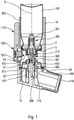
- the device comprises a main body 10 provided with a mouthpiece 400.
- This mouthpiece 400 defines a dispensing orifice through which the user will inhale when using the device.
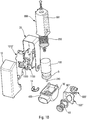
- the mouthpiece 400 can be produced in one piece with the body 10, as in the Figures 1 to 7 , or be formed on a lower body part 10 'which is fixed to said main body 10, as on the figures 8 to 10 .
- a removable protective cover 410 can be provided on said mouthpiece 400, in particular during storage periods, which the user will remove before use.
- the figure 1 shows such a protective cover, which could be of any shape.
- the main body 10 contains a reservoir 100, containing the product to be dispensed and a propellant gas, such as a gas of the HFA type, a metering valve 200 being mounted on said reservoir 100 for selectively dispensing the product.
- the metering valve 200 comprises a valve body 201 and a valve 210 axially displaceable during actuation relative to said valve body 201, and therefore relative to said reservoir 100.
- This metering valve 200 can be of any suitable type. It can be fixed to the reservoir 100 by a fixing element, preferably a crimped capsule 5, preferably with the interposition of a neck seal 4.
- valve 210 is fixed relative to the body 10, and it is the reservoir 100 which is moved axially relative to the body 10 between a distal position, which is the rest position, and a position proximal.
- valve 210 of said metering valve 200 is connected via a channel 300 to said mouthpiece 400, through which the user inhales the dispensed product.
- said valve 210 is received in a valve well 700 which at least partially defines said channel 300.
- the valve well 700 is formed in one piece with the body 10 or the lower body part 10 ′, while in the embodiments of the figures 2 to 7 , said valve well 700 is axially movable relative to said body 10.
- the device comprises an actuating element 500, 500 ′, 500 ′′, 550 movable and / or deformable between a non-actuating position, in which said metering valve 200 cannot be actuated, and a position d actuation, in which said metering valve 200 can be actuated.
- said actuating element 500, 500 ′, 500 ′′, 550 In the rest position, said actuating element 500, 500 ′, 500 ′′, 550 is in the non-actuating position, and it is the inhalation of the user through the mouthpiece 400 which moves and / or deforms said actuating element 500, 500 ', 500 ", 550 towards its actuating position.
- the actuating element can be a blocking element 500, 500 ′, 500 "which, in the non-actuating position, prevents the axial movement of the reservoir 100 in the body 10.
- this blocking element 500, 500 ′, 500 ′′ is displaced and / or deformed so that it no longer blocks the axial movement of the reservoir 100 in the body 10.
- such a axial movement of the tank 100 causes the actuation of the metering valve 200 and the distribution of a dose of product synchronized with this inhalation.
- the actuating element may be a locking element 550 which, in the non-actuating position, allows the axial displacement of the valve 210 of the metering valve 200 together with reservoir 100 in the body 10, thereby preventing the actuation of said metering valve 200 when said reservoir 100 is moved axially in the body 10 without inhalation.
- this locking element 550 is moved and / or deformed so that it blocks the axial movement of the valve 210 relative to the body 10.
- an axial movement of the reservoir 100 causes l actuation of the metering valve 200 and the distribution of a dose of product synchronized with this inhalation.
- the device comprises a trigger system controlled by the inhalation of the user, which is intended to move and / or deform said actuating element 500, 500 ′, 500 ′′, 550 from its non-actuating position to its position d actuation, when the user inhales through the mouthpiece 400.
- This triggering system comprises a member sensitive to inhalation 60, 61, 65, 66 deformable and / or movable under the effect of inhalation, this member sensitive to inhalation 60, 61, 65, 66 being adapted, when it deforms and / or moves, to move and / or deform said actuating element 500, 500 ′, 500 ′′, 550 from its non-actuating position to its actuating position.
- the inhalation-sensitive member can be produced in the form of a deformable membrane 61 defining a deformable air chamber 60, for example a bellows or a deformable pocket.
- the inhalation-sensitive member can be produced in the form of a piston 65, preferably cylindrical, sliding in a chamber 66, preferably cylindrical, non-deformable.
- the device embeds electronic modules.
- an electronic dose counter 1000 is provided.
- This counter 1000 can in particular detect the movements of the reservoir 100, for example by means of a contact sensor 1010.
- the counter 1000 could be connected to a sensor, in particular a membrane sensor, which detects the distribution of the dose of fluid product, for example in the valve well 700.
- Other means of actuating the electronic counter 1000 are also possible, for example the detection of the displacement of the valve 210 of the metering valve with respect to the valve body 201.
- the device also comprises means for transmitting signals 1100 for communicating remotely in particular information relating to the actuations of the device.
- the body 10 may include a signal transmission module, for communicating remotely with any base. Appropriate supply means are advantageously provided.
- the electronic module can in particular comprise a card comprising an electrical switch which sends a pulse.
- the module can also include a display and / or use a Bluetooth or Wifi connection to send information to an accessory device.
- Appropriate sensors can be provided, such as flow and / or pressure sensors, to detect various parameters of the inhalation flow.
- these signal emission means 1100 make it possible to transmit each dose distribution in an absolutely reliable manner, for example to a doctor or any other person wishing to monitor the use of the inhalation device by the user.
- the inhalation synchronization device guarantees that the user inhales each time he actuates the device, and the counter records each dose dispensed, as well as various associated parameters, such as the timestamp of each dispensing and the characteristics of inhalation. The doctor can thus know very exactly the conditions of use of the device by the user.
- the non-actuating position corresponds to a blocking position of the reservoir 100 in the body 10.
- this blocking position the reservoir 100 is prevented from moving by said actuating element, which will only be released when inhalation.
- the actuating element, forming a locking element is here advantageously formed by a locking ring 500, comprising at least one, preferably three axial locking tabs 501, which are elastically deformable radially outward.
- This locking ring 500 is fixed, in particular snapped on, on the tank 100, in particular on the capsule 5 which fixes the metering valve 200 on the tank 100.
- Said locking tabs 501 are supported in the rest position on a radial shoulder 710 of said valve well 700.
- This shoulder is preferably inclined downwards and radially outwards, so that when the reservoir 100 slides axially in the body 10 during actuation, said axial locking tabs 501 slide on said shoulder 710 inclined, which deforms them radially outwards.
- a trigger element 600 is mounted to slide axially around said valve well 700 between a blocking position, in which it blocks said blocking ring 500 in its non-actuating position, and a release position, in which it no longer blocks said locking ring 500.
- said trigger element 600 in the locking position, cooperates with said locking tabs 501, preventing any radial deformation towards the outside of said locking tabs 501.
- said trigger element 600 when said trigger element 600 is in the locking position, it prevents deformation radial towards the outside of said locking tabs 501, which consequently remain axially blocked by said shoulder 710 of the valve well 700, which blocks the axial movement of the reservoir 100 and therefore the actuation of the metering valve 200.
- sliding means such as balls, could be interposed between the valve well 700 and the trigger 600, to facilitate the sliding of the latter during inhalation.
- the triggering element 600 advantageously comprises a hollow central sleeve 650 which slides axially around the valve well 700.
- Two axial legs (not shown), diametrically opposite, and each connected to said central sleeve 650 may be provided to cooperate each with a respective opening of the body 10, to substantially close these openings in the locked position, and to substantially open these openings in the release position.
- These openings being closed at the start of inhalation, the inhalation flow is initially mainly transmitted to the triggering system by inhalation, in this example the deformable air chamber 60. This makes it possible to optimize this triggering by inhalation .
- the axial tabs open said openings of the body 10, which generates a call for air, and therefore increases the flow of inhalation. This optimizes the timing between the distribution of the dose and the inhalation of the user, and promotes good distribution of the dose in the lungs of the user.
- said axial tabs can be accessible from the outside through said openings. This makes it possible, if necessary, to manually move the trigger element 600, in order to be able to actuate the metering valve 200 even without inhalation, for example if the person having to receive the dose of fluid product is incapable of achieving sufficient inhalation. It is therefore a security. As a variant for this security, one could provide an axial extension (not shown) integral with the triggering element 600, extending for example laterally from the reservoir 100, and accessible by the user from outside the body 10.
- the triggering element 600 may not have the axial tabs, and the body may not have the openings 13.
- the inhalation flow could flow axially in the body 10, around the well of valve 700, which could be favored by a central sleeve 650 provided with axial cutouts allowing the passage of the air flow.
- the organ sensitive to inhalation is produced in the form of a deformable air chamber 60.
- this air chamber comprises a deformable membrane 61 which is connected on the one hand to the body 10 and on the other hand part to said trigger element 600.
- a membrane support sleeve 900 is fixedly disposed in the body 10, with a lower shoulder 910 which wedges a first edge 62 of the membrane 61 against a part 17 of the body 10.
- the second edge 63 of the membrane 61 can be fixed in a groove 630 of the triggering element 600, advantageously formed on the hollow central sleeve 650 thereof.
- the deformable membrane 61 deforms and / or contracts under the effect of the depression generated by inhalation, causing the trigger element 600 to move from its blocking position to its release position. This then allows the radial deformation of said locking tabs 501 and therefore the displacement of said locking ring 500 forming the actuating element from its non-actuating position to its actuating position.
- the figure 1 shows a membrane deformable 61 produced in the form of a pocket or a diaphragm. Of course, other shapes are also possible, for example a bellows as shown in the figures 8 to 10 .
- the valve 200 is therefore actuated only at the time of inhalation, so that the dose of fluid product is expelled out of the dispensing orifice simultaneously with inhalation.
- the distribution of the dose is counted by the counter 1000, and the information relating to the taking of the dose, such as for example the time stamp and the parameters of the inhalation flow, are transmitted by the emission means 1100.
- the user When the user wishes to use the device, he places the mouthpiece 400 in his mouth, and manually presses on the bottom of the tank 100, that is to say the upper surface of said tank 100 in the position of the figure 1 .
- the reservoir 100 will then be blocked and prevented from sliding in the body 10 by the locking tabs 501 of the locking ring 500, which rest on the shoulder 710 of the valve well 700.
- the reservoir 100 can carry out a short stroke before being blocked, this initial small stroke being however insufficient to actuate the metering valve 200.
- the triggering element 600 is brought up by the elasticity of the membrane 61.
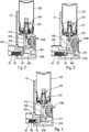
- the actuating element is a locking element 550 which, in the non-actuating position, allows the axial displacement of the valve 210 of the metering valve 200 together with the reservoir 100 in the body 10, preventing the actuation of said metering valve 200 when said reservoir 100 is moved axially in the body 10 without inhalation.
- this locking element 550 is moved and / or deformed so that it blocks the axial movement of the valve 210 relative to the body 10.
- an axial movement of the reservoir 100 causes l actuation of the metering valve 200 and the distribution of a dose of product synchronized with this inhalation.
- the inhalation-sensitive member is produced in the form of a piston 65 sliding in a chamber 66, between a rest position and an inhalation position.
- the chamber 66 is advantageously formed in the mouthpiece 400.
- Said piston 65 is connected to said locking element 550, advantageously by a rod 540.
- the locking element 550 can be formed at the end of said rod 540 opposite to said piston 65, and comprises an axial projection 551.
- a spring 67 advantageously disposed in chamber 66, is adapted to bring said piston 65 back to its rest position when there is no more inhalation through the mouthpiece 400.
- said projection is offset radially relative to the valve well 700, so that the latter can move axially in the body 10, together with the valve 210 of the metering valve 200 and the reservoir 100.
- the valve 210 does not move relative to the reservoir 100, and the metering valve 200 is therefore not actuated.
- the piston 65 moves radially (relative to the axis A of movement of the reservoir 100 in the body 10) in the chamber 66 under the effect of the vacuum created by inhalation.
- the projection 551 therefore also moves radially, and is positioned under said valve well 700, thus forming a stop for the axial displacement downwards of said valve well.
- the pressure exerted by the user on the bottom of the reservoir 100 will move the latter axially downward in the body, and the valve well 700, now axially fixed relative to the body 10, will therefore block the valve 210 of the metering valve axially relative to the body 10, so that it will sink into the valve body, thereby causing the actuation of the metering valve 200 and the distribution of a dose of fluid.
- the dose counter 1000 cannot measure this displacement axial of the reservoir 100.
- sensors detecting the distribution of the fluid product, in particular in the valve well 700, or sensors detecting the displacement of the valve 210 of the metering valve 200 relative to the valve body 201 will be preferred.
- FIG. 5 to 7 illustrate yet another embodiment.
- the inhalation trigger system is similar to that described above with reference to figures 2 to 4 , with a piston 65 sliding radially in a chamber 66 of the mouthpiece 400.
- the actuating element is again produced in the form of a blocking element 500 ′, which, in the non-actuating position, prevents the axial movement of the reservoir 100 in the body 10.
- this blocking element 500 ′ is moved and / or deformed so that it no longer blocks the axial movement of the reservoir 100 in the body 10.
- such an axial movement of the reservoir 100 causes actuation of the metering valve 200 and distribution of a dose of product synchronized with this inhalation.
- This blocking element 500 ′ can in particular be assembled on said rod 540 secured to the piston 65, and include an axial extension 505 which, in the non-actuating position extends axially in the body to cooperate with and axially block said reservoir 100.
- the rod 540 moves radially to the left (in the orientation of the Figures 5 to 7 ), which will cause the deformation of said axial extension 505, and therefore release the axial movement of the reservoir 100.
- the valve well 700 is mounted movably in the body 10, but it could also be fixed.
- the lower end 506 of said axial extension 505 is fixed radially and axially relative to the body 10.
- the rod 540 moves radially, it pulls radially on said axial extension, which deforms, for example bends or pivots, so that the upper end disengages from the reservoir 100 and releases the latter for its axial displacement.
- the blocking element 500 ′ could have any other suitable form. In particular, one can consider the use of an articulated toggle.
- the figure 7 shows an alternative embodiment, in which the rod 540 is accessible from the outside of the body 10 through an opening 19 of said body 10.
- an actuating member 800 is assembled on the upper end of the reservoir 100, axially opposite said metering valve 200.
- This actuating member 800 comprises a hollow sleeve 801 placed in the body 10 around the reservoir 100, with a spring 850 arranged between the bottom of the tank 100 and the upper edge closed of said hollow sleeve 801.
- the hollow sleeve 801 is axially movable relative to said reservoir 100 between a rest position and a loaded position.
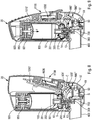
- a lateral actuating handle 20 is pivotally mounted on the body 10.
- This handle when moved from its rest position, visible on the figure 8 , towards its position of use, visible on the figure 9 , axially displaces said actuating member 800 to compress the spring 850.
- This can in particular be done by means of a cam on the handle 20 cooperating with a complementary profile on the actuating member 800.
- said spring 850 is compressed and biases said reservoir 100 axially towards its actuating position.
- said handle 20 comprises a biasing member which biases said handle 20 towards its rest position.
- this handle 20 is not necessary, nor, moreover, the actuating member 800, the user being able to directly press the bottom of the tank, as in the embodiments previously described.
- valve 200 The actuation of the valve 200 and the expulsion of a dose of fluid product are therefore only possible if the user inhales and simultaneously presses axially on the reservoir 100 to actuate the valve 200.
- this support axial on the tank 100 can be done via the actuating member 800 which compresses the spring 850.
- the user could directly press on the bottom of the tank 100.
- it is the handle 20 which will generate this axial support, also via the actuating member 800 in the example shown.
- an automatic actuation system which would apply this axial support to the tank 100 independently of the user.
- the actuating element is a blocking element 500 "which, in the non-actuating position, prevents axial movement of the reservoir 100 in the body 10.
- the locking element 500 " is advantageously mounted pivoting about an axis B on the body 10 or on the body part 10 'between a locking position and an actuation position.
- said axis B passes through a lower edge of said blocking element 500 ".
- the blocking element 500 "comprises at least one, preferably two blocking extensions 501 ', which cooperate in the blocking position with the reservoir 100 (advantageously with the crimping cap 5).
- the blocking element 500 is retained in the blocking position by a trigger element 600 '.
- This trigger element 600' is pivotally mounted about an axis C on the body 10, on the body part 10 'or on the handle 20, between a locking position, in which it blocks said blocking element 500 "in its blocking position, and a release position, in which it no longer blocks said blocking element 500".
- said axis C passes approximately in the middle of said trigger element 600 '.
- the axes B and C are parallel.
- the locking element 500 "and the triggering element 600 ' together define a lock.
- said triggering element 600' comprises a locking shoulder which, in the locking position, cooperates with a projection of the locking element 500 ", preventing the pivoting of said blocking element 500" from its blocking position.
- said triggering element 600 ' when said triggering element 600 'is in the locking position, it prevents the displacement of the blocking element 500 "towards its actuating position , which blocks the axial movement of the reservoir 100 and therefore the actuation of the metering valve 200.
- the force required to pivot the triggering element 600 ' is very low and can be generated by the deformable membrane 61, which makes it possible to transform the depression generated by inhalation into force unlocking.
- the lower part of the body 10 ′ has an opening 13 connected with the interior of the body 10.
- This opening 13 is closed at rest and at the start of inhalation by a valve 14, so that the inhalation flow is initially mainly transmitted to the triggering system by inhalation, in this example the deformable air chamber 60.
- inhalation in this example the deformable air chamber 60.
- the blocking element 500 "has moved to its actuating position under the effect of inhalation, and therefore when the user can actuate the metering valve 200 to dispense a dose of fluid, said element blocking 500 "moves said valve 14 to an open position.
- said openings 13 are thus opened, a call for air is generated, which makes it possible to increase the flow of inhalation. This optimizes the timing between the distribution of the dose and the inhalation of the user, and promotes good distribution of the dose in the lungs of the user.
- the triggering element 600 ' can be accessible from outside the body 10 and / or from the lower part of the body 10'. This allows in the event of the need to manually move the triggering element 600 ′, in order to be able to actuate the metering valve 200 even without inhalation, for example if the person having to receive the dose of fluid product is incapable of achieving sufficient inhalation. It is therefore a security.
- the organ sensitive to inhalation is produced in the form of a deformable air chamber 60.
- this air chamber comprises a deformable membrane 61 which is connected on the one hand to said lower body part 10 'and on the other hand to said trigger element 600'.
- the membrane 61 has the shape of a bellows and forms a substantially sealed chamber. Other shapes are possible, including a simple pocket or diaphragm.
- a stud can fix said membrane 61 to an orifice of said trigger element 600 '.
- the deformable membrane 61 deforms and / or contracts under the effect of the depression generated by inhalation, causing the displacement of the trigger element 600 'from its locking position to its release position. .
- This makes it possible to open the lock defined between the blocking element 500 "and the triggering element 600 ', and therefore the displacement of said blocking element 500" from its blocking position towards its actuating position.
- valve 200 is therefore actuated only at the time of inhalation, so that the dose of fluid product is expelled out of the dispensing orifice simultaneously with inhalation.
- the actuating member 800 comprises a locking tab (not shown), capable of cooperating in the rest position with said trigger element 600 ', to prevent it from moving towards its release position.
- a locking tab (not shown)
- the lock will not be released, since the triggering element 600 ′ cannot pivot.
- the air chamber 60 being substantially sealed, and the valve 14 being closed on the opening 13, the user very quickly realizes that he cannot inhale properly at through the mouthpiece 400, which reminds him that the axial support must first be exerted on the reservoir 100 before inhaling.
- the user When the user wishes to use the device, he places the mouthpiece 400 in his mouth, and manually exerts an axial support on the bottom of the tank 100, that is to say the upper surface of said tank 100 in the position of FIGS.
- the reservoir 100 is blocked and prevented from sliding axially in the body 10 by the blocking extensions 501 of the blocking element 500 ".
- the blocking of the triggering element 600 ′ is eliminated by the axial displacement of the member actuation 800.
- the user releases his pressure on the bottom of the reservoir 100, it rises axially in the body in the direction of its rest position under the effect of the return spring of the valve 200, and simultaneously the valve 210 of the metering valve returns to the rest position, by loading a new dose of fluid product into the valve chamber.
- the triggering element 600 is returned to its initial position by the elasticity of the membrane 61 and / or by the actuating member 800 which returns to its rest position.
- the blocking element 500 "returns to its blocking position, advantageously via an elastic element, such as a spring or an elastomer element (not shown).
- the device is then ready for another use.
- the electronic dose counter 1000 can be assembled in the handle 20.
- This counter 1000 can in particular detect the movements of the reservoir 100, for example by means of a slide 1010 ′ which is moved by the reservoir 100 or by the blocking element 500 ", when they reach the dispensing position.
- the counter 1000 could be connected to a sensor, in particular a membrane sensor, which detects the distribution of the dose of fluid product, for example in the valve well 700.
- Other means of actuating the electronic counter 1000 are also possible, for example the detection of the displacement of the valve 210 of the metering valve relative to the valve body 201.
- the device also comprises means for transmitting signals 1100 for communicating remotely in particular information relating to the actuations of the device.
- the body 10 and / or the handle 20 may include a signal transmission module, for communicating remotely with any base. Appropriate supply means are advantageously provided.
- the electronic modules 1000, 1100 as well as the associated slide 1010 ′ are placed in the handle 20, movable relative to the body 10. But as a variant, one can imagine modules fixed relative to the body 10.
- the present invention is particularly applicable for the treatment of asthma attacks or COPD (Broncho Pneumopathie Obstructive) in use with formulations of the salbutamol, aclidinium, formoterol, tiotropium, budesonide, fluticasone, indacaterol, glycopyrronium, salmeterol, umeclidinium bromide, vilanterol, olodaterol, striverdi, or any combination of these formulations.
- COPD Broncho Pneumopathie Obstructive
Landscapes
- Health & Medical Sciences (AREA)
- Engineering & Computer Science (AREA)
- Life Sciences & Earth Sciences (AREA)
- Anesthesiology (AREA)
- General Health & Medical Sciences (AREA)
- Biomedical Technology (AREA)
- Heart & Thoracic Surgery (AREA)
- Hematology (AREA)
- Veterinary Medicine (AREA)
- Animal Behavior & Ethology (AREA)
- Public Health (AREA)
- Pulmonology (AREA)
- Bioinformatics & Cheminformatics (AREA)
- Biophysics (AREA)
- Mechanical Engineering (AREA)
- Containers And Packaging Bodies Having A Special Means To Remove Contents (AREA)
- Nozzles (AREA)
Claims (16)
- Vorrichtung zur inhalationssynchronisierten Abgabe eines flüssigen Produkts, umfassend einen Körper (10; 10'), der mit einem Mundstück (400) versehen ist, einen Produkttank (100), der ein flüssiges Produkt und ein Treibgas enthält, und der axial verschiebbar in dem Körper (10; 10') angebracht ist, ein Dosierventil (200), umfassend ein Ventil (210), das auf dem Tank (100) befestigt ist, um das flüssige Produkt selektiv abzugeben, dadurch gekennzeichnet, dass die Vorrichtung umfasst:- ein Betätigungselement (500, 500', 500"; 550), das zwischen einer Nichtbetätigungsposition, in der das Dosierventil (200) nicht betätigbar ist, und einer Betätigungsposition, in der das Dosierventil (200) betätigbar ist, bewegbar und/oder verformbar ist,- ein inhalationsgesteuertes Auslösesystem, umfassend ein inhalationsempfindlichen Element (60, 61; 65, 66), das durch die Inhalation verformbar und/oder bewegbar ist, wobei das inhalationsempfindliche Element (60, 61; 65, 66) bei Verformung und/oder Bewegung das Betätigungselement (500, 500', 500"; 550) aus seiner Nichtbetätigungsposition in seine Betätigungsposition bewegt und/oder verformt wird,- einen elektronischen Dosiszähler (1000), und- Signalübertragungseinrichtungen (1100) zum Fernübermitteln insbesondere von Informationen, die sich auf die Betätigungen der Vorrichtung beziehen.
- Vorrichtung nach Anspruch 1, wobei das Betätigungselement ein Blockierelement (500, 500', 500") ist, das, in Nichtbetätigungsposition, einerseits mit dem Körper (10; 10') und andererseits mit dem Tank (100) zusammenwirkt, um die axiale Bewegung des Tanks (100) in dem Körper (10; 10') zu verhindern.
- Vorrichtung nach Anspruch 2, umfassend ein Auslöseelement (600, 600'), das zwischen einer Verriegelungsposition, in der es das Blockierelement (500, 500") in seiner Blockierposition blockiert, und einer Freigabeposition, in er es das Blockierelement (500, 500") nicht blockiert, bewegbar und/oder verformbar ist.
- Vorrichtung nach Anspruch 3, wobei das inhalationsgesteuerte Auslösesysteme eine verformbare Membran (61) umfasst, die eine verformbare Luftkammer (60) definiert, wobei die verformbare Membran (61) an dem Auslöseelement (600, 600') befestigt ist, wobei die verformbare Membran (61) während der Inhalation derart verformt wird, dass sie das Auslöseelement (600, 600') von seiner Blockierposition in seine Freigabeposition bewegt.
- Vorrichtung nach Anspruch 3 oder 4, wobei das Auslöseelement (600, 600') für den Benutzer manuell zugänglich ist, um auch ohne Inhalation manuell in seine Freigabeposition bewegt werden zu können.
- Vorrichtung nach einem der vorhergehenden Ansprüche, wobei das Betätigungselement (800) auf dem Tank (100) auf der dem Dosierventil (200) axial gegenüberliegenden Seite befestigt ist, wobei das Betätigungselement (800) eine hohle Hülse (801) umfasst, die in Bezug auf den Tank (100) zwischen einer Ruheposition und einer geladenen Position axial bewegbar ist, wobei eine Feder (850) zwischen dem Boden des Tanks (100) und dem geschlossenen oberen Rand der hohlen Hülse (801) derart angeordnet ist, dass, wenn der Benutzer manuell auf das Betätigungselement (800) drückt, um es in seine geladene Position zu bewegen, die Feder (850) zusammengedrückt wird, um eine axiale Kraft (F) auf den Tank (100) zu übertragen.
- Vorrichtung nach Anspruch 6, wobei ein seitlicher Betätigungsgriff (20) schwenkbar zwischen einer Ruheposition und einer Betriebsposition auf dem Körper (10; 10') montiert, in der er das Betätigungselement (800) axial in seine geladene Position bewegt.
- Vorrichtung nach einem der vorhergehenden Ansprüche, wobei der Körper (10; 10') eine Öffnung (13) umfasst, die das Mundstück (400) mit dem Inneren des Körpers (10) verbindet, wobei die Öffnung (13) zu Beginn der Inhalation mit einer Klappe (14) derart verschlossen ist, dass der Inhalationsstrom anfangs hauptsächlich auf das inhalationsbedingte Auslösesystem übertragen wird.
- Vorrichtung nach Anspruch 8, wobei die Klappe (14) geöffnet wird, wenn das Blockierelement (500") in seine Betätigungsposition bewegt wird.
- Vorrichtung nach Anspruch 2, wobei das Blockierelement (500') eine axiale Verlängerung (505) umfasst, wovon ein unteres Ende (506) in Bezug auf den Körper (10) radial und axial befestigt ist und ein oberes Ende mit dem Tank (100) in Nichtbetätigungsposition zusammenwirkt.
- Vorrichtung nach Anspruch 10, wobei das inhalationsgesteuerte Auslösesystem einen Kolben (65) umfasst, der in einer Kammer (66) zwischen einer Ruheposition und einer Inhalationsposition verschiebbar ist.
- Vorrichtung nach Anspruch 11, wobei das Blockierelement (500') an einer Stange (540) befestigt ist, die an dem Kolben (65) derart befestigt ist, dass sich die Stange (540) während der Inhalation radial bewegt, wobei sie die axiale Verlängerung (505) in ihre Betätigungsposition verformt und/oder bewegt.
- Vorrichtung nach Anspruch 1, wobei das Betätigungselement ein Verriegelungselement (550) ist, das, in der Nichtbetätigungsposition, die axiale Bewegung des Ventils (210) des Dosierventils (200) zusammen mit dem Tank (100) in dem Körper (10) ermöglicht, und dabei die Betätigung des Dosierventils (200) verhindert, wenn der Tank (100) in dem Körper (10) ohne Inhalation axial bewegt wird.
- Vorrichtung nach Anspruch 13, wobei das Verriegelungselement (550) während der Inhalation derart bewegt und/oder verformt wird, dass es die axiale Bewegung des Ventils (210) in Bezug auf den Körper (10) blockiert.
- Vorrichtung nach Anspruch 14, wobei das inhalationsgesteuerte Auslösesystem einen Kolben (65) umfasst, der in einer Kammer (66) zwischen einer Ruheposition und einer Inhalationsposition verschiebbar ist.
- Vorrichtung nach Anspruch 15, wobei das Verriegelungselement (550) an einer Stange (540) befestigt ist, die an dem Kolben (65) derart befestigt ist, dass sich die Stange (540) während der Inhalation radial bewegt, wobei das Verriegelungselement (550) in seine Betätigungsposition bewegt wird, in der es verhindert, dass das Ventil (210) des Dosierventils (200) axial bewegt wird, wenn der Tank (100) axial in dem Körper (10) bewegt wird.
Applications Claiming Priority (2)
| Application Number | Priority Date | Filing Date | Title |
|---|---|---|---|
| FR1653375A FR3050116B1 (fr) | 2016-04-15 | 2016-04-15 | Dispositif de distribution de produit fluide synchronise avec l'inhalation |
| PCT/FR2017/050894 WO2017178767A1 (fr) | 2016-04-15 | 2017-04-13 | Dispositif de distribution de produit fluide synchronise avec l'inhalation |
Publications (2)
| Publication Number | Publication Date |
|---|---|
| EP3442632A1 EP3442632A1 (de) | 2019-02-20 |
| EP3442632B1 true EP3442632B1 (de) | 2020-02-05 |
Family
ID=56511699
Family Applications (1)
| Application Number | Title | Priority Date | Filing Date |
|---|---|---|---|
| EP17723447.3A Active EP3442632B1 (de) | 2016-04-15 | 2017-04-13 | Vorrichtung zur abgabe eines flüssigen produktes mit inhalationssynchronisation |
Country Status (6)
| Country | Link |
|---|---|
| US (1) | US11547814B2 (de) |
| EP (1) | EP3442632B1 (de) |
| JP (1) | JP6936249B2 (de) |
| CN (1) | CN109069766B (de) |
| FR (1) | FR3050116B1 (de) |
| WO (1) | WO2017178767A1 (de) |
Families Citing this family (7)
| Publication number | Priority date | Publication date | Assignee | Title |
|---|---|---|---|---|
| FR3050114B1 (fr) * | 2016-04-15 | 2021-12-03 | Aptar France Sas | Dispositif de distribution de produit fluide synchronise avec l'inhalation. |
| FR3074051B1 (fr) * | 2017-11-29 | 2019-11-22 | Aptar France Sas | Dispositif de distribution de produit fluide synchronise avec l'inhalation |
| FR3077496B1 (fr) | 2018-02-06 | 2024-03-15 | Nemera La Verpilliere | Dispositif d’assistance a l’utilisation d’un dispositif de distribution a activation axiale |
| EP3693044A1 (de) * | 2019-02-07 | 2020-08-12 | Koninklijke Philips N.V. | Durch atmung betätigte inhalatoren |
| CA3161873A1 (en) * | 2019-12-10 | 2021-06-17 | Trudell Medical International | Integrated dose counter |
| FR3117046B1 (fr) * | 2020-12-09 | 2023-02-10 | Aptar France Sas | Dispositif de distribution de doses de poudre |
| CN116059481B (zh) * | 2023-02-07 | 2025-09-09 | 青岛未来移动医疗科技有限公司 | 一种雾化器定量药杯、定量给药系统及控制方法 |
Family Cites Families (23)
| Publication number | Priority date | Publication date | Assignee | Title |
|---|---|---|---|---|
| FR2658081B1 (fr) * | 1990-02-09 | 1995-06-30 | Pesenti Yvan | Dispositif d'automatisation et synchronisation des appareils aerosols a pompe doseuse. |
| GB9015077D0 (en) * | 1990-07-09 | 1990-08-29 | Riker Laboratories Inc | Inhaler |
| US5060643A (en) * | 1990-08-07 | 1991-10-29 | Tenax Corporation | Breath-activated inhalation device |
| FR2667509B1 (fr) * | 1990-10-04 | 1995-08-25 | Valois | Inhalateur a poudre, dispositif de conditionnement de microdoses de poudre sous forme de bandes adaptees a etre utilisees dans un inhalateur a poudre, et procede de fabrication de ces bandes. |
| US5954047A (en) * | 1997-10-17 | 1999-09-21 | Systemic Pulmonary Development, Ltd. | Methods and apparatus for delivering aerosolized medication |
| FR2775668B1 (fr) * | 1998-03-04 | 2000-05-19 | Tebro | Dispositif de distribution de produit fluide declenche par l'inhalation |
| GB0114175D0 (en) * | 2001-06-11 | 2001-08-01 | Glaxo Group Ltd | Medicament dispenser |
| GB0222295D0 (en) * | 2002-09-25 | 2002-10-30 | 3M Innovative Properties Co | Breath actuated medicament dispensing devices |
| US7296567B2 (en) * | 2002-09-25 | 2007-11-20 | 3M Innovative Properties Company | Breath actuated aerosol dispensers |
| GB0304000D0 (en) * | 2003-02-21 | 2003-03-26 | Clinical Designs Ltd | Dispenser |
| DE202004021188U1 (de) * | 2003-07-14 | 2007-03-15 | Neo-Inhalation Ltd., Odiham | Inhalationsgerät |
| GB0518400D0 (en) * | 2005-09-09 | 2005-10-19 | Clinical Designs Ltd | Dispenser |
| FR2904229B1 (fr) * | 2006-07-25 | 2008-10-10 | Valois Sas | Dispositif de distribution de produit fluide. |
| RU2009105638A (ru) * | 2006-08-22 | 2010-09-27 | Глакса Груп Лимитед (GB) | Средство приведения в действие для ингалятора |
| US8225790B2 (en) * | 2007-01-02 | 2012-07-24 | Astrazeneca Ab | Inhaler 624 |
| MY163805A (en) * | 2009-08-07 | 2017-10-31 | Kind Consumer Ltd | An inhaler |
| JP6067554B2 (ja) * | 2010-06-18 | 2017-01-25 | ベーリンガー インゲルハイム インターナショナル ゲゼルシャフト ミット ベシュレンクテル ハフツング | 吸入器 |
| FR2973012B1 (fr) * | 2011-03-21 | 2013-04-26 | Valois Sas | Dispositif de distribution de produit fluide a actionnement lateral. |
| GB201118845D0 (en) * | 2011-11-01 | 2011-12-14 | Euro Celtique Sa | Dispenser |
| GB201322677D0 (en) * | 2013-12-20 | 2014-02-05 | 3M Innovative Properties Co | Actuator for an inhaler |
| AU2015245626B2 (en) * | 2014-04-07 | 2019-10-31 | Boehringer Ingelheim International Gmbh | Inhalation training device and system for practicing of an inhalation process of a patient |
| GB201408229D0 (en) * | 2014-05-09 | 2014-06-25 | Norton Waterford Ltd | Aerosol device |
| FR3050114B1 (fr) * | 2016-04-15 | 2021-12-03 | Aptar France Sas | Dispositif de distribution de produit fluide synchronise avec l'inhalation. |
-
2016
- 2016-04-15 FR FR1653375A patent/FR3050116B1/fr active Active
-
2017
- 2017-04-13 WO PCT/FR2017/050894 patent/WO2017178767A1/fr not_active Ceased
- 2017-04-13 CN CN201780023120.5A patent/CN109069766B/zh active Active
- 2017-04-13 JP JP2018553994A patent/JP6936249B2/ja active Active
- 2017-04-13 US US16/093,498 patent/US11547814B2/en active Active
- 2017-04-13 EP EP17723447.3A patent/EP3442632B1/de active Active
Non-Patent Citations (1)
| Title |
|---|
| None * |
Also Published As
| Publication number | Publication date |
|---|---|
| US20210187210A1 (en) | 2021-06-24 |
| US11547814B2 (en) | 2023-01-10 |
| JP6936249B2 (ja) | 2021-09-15 |
| JP2019513478A (ja) | 2019-05-30 |
| WO2017178767A1 (fr) | 2017-10-19 |
| FR3050116A1 (fr) | 2017-10-20 |
| FR3050116B1 (fr) | 2020-05-15 |
| CN109069766A (zh) | 2018-12-21 |
| CN109069766B (zh) | 2021-03-23 |
| EP3442632A1 (de) | 2019-02-20 |
Similar Documents
| Publication | Publication Date | Title |
|---|---|---|
| EP3442631B1 (de) | Vorrichtung zur inhalationssynchronisierten ausgabe eines flüssigprodukts | |
| EP3442632B1 (de) | Vorrichtung zur abgabe eines flüssigen produktes mit inhalationssynchronisation | |
| EP3442630B1 (de) | Vorrichtung zur inhalationssynchronisierten ausgabe eines flüssigprodukts | |
| EP4100088B1 (de) | Vorrichtung zur ausgabe eines mit inhalation synchronisierten flüssigproduktes und verfahren zum zusammenbau dieser vorrichtung | |
| EP3921003B1 (de) | Vorrichtung zur inhalationssynchronisierten abgabe eines flüssigen produkts | |
| EP3220985B1 (de) | Inhalationsbetätigte abgabevorrichtung für ein flüssiges produkt. | |
| EP3921002B1 (de) | Vorrichtung zur inhalationssynchronisierten abgabe eines flüssigen produkts | |
| EP3697483B1 (de) | Vorrichtung zur inhalationssynchronisierten abgabe eines flüssigen produkts | |
| EP3717048B1 (de) | Vorrichtung zur inhalationssynchronisierten ausgabe eines flüssigprodukts | |
| EP3697482B1 (de) | Vorrichtung zur inhalationssynchronisierten abgabe eines flüssigen produkts | |
| EP3886952B1 (de) | Vorrichtung zur inhalationssynchronisierten ausgabe eines flüssigprodukts | |
| FR2787031A1 (fr) | Dispositif d'inhalation ameliore |
Legal Events
| Date | Code | Title | Description |
|---|---|---|---|
| STAA | Information on the status of an ep patent application or granted ep patent |
Free format text: STATUS: UNKNOWN |
|
| STAA | Information on the status of an ep patent application or granted ep patent |
Free format text: STATUS: THE INTERNATIONAL PUBLICATION HAS BEEN MADE |
|
| PUAI | Public reference made under article 153(3) epc to a published international application that has entered the european phase |
Free format text: ORIGINAL CODE: 0009012 |
|
| STAA | Information on the status of an ep patent application or granted ep patent |
Free format text: STATUS: REQUEST FOR EXAMINATION WAS MADE |
|
| 17P | Request for examination filed |
Effective date: 20181109 |
|
| AK | Designated contracting states |
Kind code of ref document: A1 Designated state(s): AL AT BE BG CH CY CZ DE DK EE ES FI FR GB GR HR HU IE IS IT LI LT LU LV MC MK MT NL NO PL PT RO RS SE SI SK SM TR |
|
| AX | Request for extension of the european patent |
Extension state: BA ME |
|
| DAV | Request for validation of the european patent (deleted) | ||
| DAX | Request for extension of the european patent (deleted) | ||
| REG | Reference to a national code |
Ref country code: DE Ref legal event code: R079 Ref document number: 602017011424 Country of ref document: DE Free format text: PREVIOUS MAIN CLASS: A61M0015000000 Ipc: A61M0016000000 |
|
| GRAP | Despatch of communication of intention to grant a patent |
Free format text: ORIGINAL CODE: EPIDOSNIGR1 |
|
| STAA | Information on the status of an ep patent application or granted ep patent |
Free format text: STATUS: GRANT OF PATENT IS INTENDED |
|
| RIC1 | Information provided on ipc code assigned before grant |
Ipc: A61M 16/00 20060101AFI20190729BHEP Ipc: A61M 15/00 20060101ALI20190729BHEP |
|
| INTG | Intention to grant announced |
Effective date: 20190904 |
|
| GRAS | Grant fee paid |
Free format text: ORIGINAL CODE: EPIDOSNIGR3 |
|
| GRAA | (expected) grant |
Free format text: ORIGINAL CODE: 0009210 |
|
| STAA | Information on the status of an ep patent application or granted ep patent |
Free format text: STATUS: THE PATENT HAS BEEN GRANTED |
|
| AK | Designated contracting states |
Kind code of ref document: B1 Designated state(s): AL AT BE BG CH CY CZ DE DK EE ES FI FR GB GR HR HU IE IS IT LI LT LU LV MC MK MT NL NO PL PT RO RS SE SI SK SM TR |
|
| REG | Reference to a national code |
Ref country code: GB Ref legal event code: FG4D Free format text: NOT ENGLISH |
|
| REG | Reference to a national code |
Ref country code: AT Ref legal event code: REF Ref document number: 1229479 Country of ref document: AT Kind code of ref document: T Effective date: 20200215 |
|
| REG | Reference to a national code |
Ref country code: DE Ref legal event code: R096 Ref document number: 602017011424 Country of ref document: DE |
|
| REG | Reference to a national code |
Ref country code: IE Ref legal event code: FG4D Free format text: LANGUAGE OF EP DOCUMENT: FRENCH |
|
| REG | Reference to a national code |
Ref country code: CH Ref legal event code: EP |
|
| REG | Reference to a national code |
Ref country code: NL Ref legal event code: MP Effective date: 20200205 |
|
| PG25 | Lapsed in a contracting state [announced via postgrant information from national office to epo] |
Ref country code: NO Free format text: LAPSE BECAUSE OF FAILURE TO SUBMIT A TRANSLATION OF THE DESCRIPTION OR TO PAY THE FEE WITHIN THE PRESCRIBED TIME-LIMIT Effective date: 20200505 Ref country code: PT Free format text: LAPSE BECAUSE OF FAILURE TO SUBMIT A TRANSLATION OF THE DESCRIPTION OR TO PAY THE FEE WITHIN THE PRESCRIBED TIME-LIMIT Effective date: 20200628 Ref country code: FI Free format text: LAPSE BECAUSE OF FAILURE TO SUBMIT A TRANSLATION OF THE DESCRIPTION OR TO PAY THE FEE WITHIN THE PRESCRIBED TIME-LIMIT Effective date: 20200205 Ref country code: RS Free format text: LAPSE BECAUSE OF FAILURE TO SUBMIT A TRANSLATION OF THE DESCRIPTION OR TO PAY THE FEE WITHIN THE PRESCRIBED TIME-LIMIT Effective date: 20200205 |
|
| REG | Reference to a national code |
Ref country code: LT Ref legal event code: MG4D |
|
| PG25 | Lapsed in a contracting state [announced via postgrant information from national office to epo] |
Ref country code: GR Free format text: LAPSE BECAUSE OF FAILURE TO SUBMIT A TRANSLATION OF THE DESCRIPTION OR TO PAY THE FEE WITHIN THE PRESCRIBED TIME-LIMIT Effective date: 20200506 Ref country code: IS Free format text: LAPSE BECAUSE OF FAILURE TO SUBMIT A TRANSLATION OF THE DESCRIPTION OR TO PAY THE FEE WITHIN THE PRESCRIBED TIME-LIMIT Effective date: 20200605 Ref country code: HR Free format text: LAPSE BECAUSE OF FAILURE TO SUBMIT A TRANSLATION OF THE DESCRIPTION OR TO PAY THE FEE WITHIN THE PRESCRIBED TIME-LIMIT Effective date: 20200205 Ref country code: LV Free format text: LAPSE BECAUSE OF FAILURE TO SUBMIT A TRANSLATION OF THE DESCRIPTION OR TO PAY THE FEE WITHIN THE PRESCRIBED TIME-LIMIT Effective date: 20200205 Ref country code: SE Free format text: LAPSE BECAUSE OF FAILURE TO SUBMIT A TRANSLATION OF THE DESCRIPTION OR TO PAY THE FEE WITHIN THE PRESCRIBED TIME-LIMIT Effective date: 20200205 Ref country code: BG Free format text: LAPSE BECAUSE OF FAILURE TO SUBMIT A TRANSLATION OF THE DESCRIPTION OR TO PAY THE FEE WITHIN THE PRESCRIBED TIME-LIMIT Effective date: 20200505 |
|
| PG25 | Lapsed in a contracting state [announced via postgrant information from national office to epo] |
Ref country code: NL Free format text: LAPSE BECAUSE OF FAILURE TO SUBMIT A TRANSLATION OF THE DESCRIPTION OR TO PAY THE FEE WITHIN THE PRESCRIBED TIME-LIMIT Effective date: 20200205 |
|
| PG25 | Lapsed in a contracting state [announced via postgrant information from national office to epo] |
Ref country code: ES Free format text: LAPSE BECAUSE OF FAILURE TO SUBMIT A TRANSLATION OF THE DESCRIPTION OR TO PAY THE FEE WITHIN THE PRESCRIBED TIME-LIMIT Effective date: 20200205 Ref country code: DK Free format text: LAPSE BECAUSE OF FAILURE TO SUBMIT A TRANSLATION OF THE DESCRIPTION OR TO PAY THE FEE WITHIN THE PRESCRIBED TIME-LIMIT Effective date: 20200205 Ref country code: LT Free format text: LAPSE BECAUSE OF FAILURE TO SUBMIT A TRANSLATION OF THE DESCRIPTION OR TO PAY THE FEE WITHIN THE PRESCRIBED TIME-LIMIT Effective date: 20200205 Ref country code: EE Free format text: LAPSE BECAUSE OF FAILURE TO SUBMIT A TRANSLATION OF THE DESCRIPTION OR TO PAY THE FEE WITHIN THE PRESCRIBED TIME-LIMIT Effective date: 20200205 Ref country code: CZ Free format text: LAPSE BECAUSE OF FAILURE TO SUBMIT A TRANSLATION OF THE DESCRIPTION OR TO PAY THE FEE WITHIN THE PRESCRIBED TIME-LIMIT Effective date: 20200205 Ref country code: RO Free format text: LAPSE BECAUSE OF FAILURE TO SUBMIT A TRANSLATION OF THE DESCRIPTION OR TO PAY THE FEE WITHIN THE PRESCRIBED TIME-LIMIT Effective date: 20200205 Ref country code: SM Free format text: LAPSE BECAUSE OF FAILURE TO SUBMIT A TRANSLATION OF THE DESCRIPTION OR TO PAY THE FEE WITHIN THE PRESCRIBED TIME-LIMIT Effective date: 20200205 Ref country code: SK Free format text: LAPSE BECAUSE OF FAILURE TO SUBMIT A TRANSLATION OF THE DESCRIPTION OR TO PAY THE FEE WITHIN THE PRESCRIBED TIME-LIMIT Effective date: 20200205 |
|
| REG | Reference to a national code |
Ref country code: DE Ref legal event code: R097 Ref document number: 602017011424 Country of ref document: DE |
|
| REG | Reference to a national code |
Ref country code: AT Ref legal event code: MK05 Ref document number: 1229479 Country of ref document: AT Kind code of ref document: T Effective date: 20200205 |
|
| PG25 | Lapsed in a contracting state [announced via postgrant information from national office to epo] |
Ref country code: MC Free format text: LAPSE BECAUSE OF FAILURE TO SUBMIT A TRANSLATION OF THE DESCRIPTION OR TO PAY THE FEE WITHIN THE PRESCRIBED TIME-LIMIT Effective date: 20200205 |
|
| REG | Reference to a national code |
Ref country code: CH Ref legal event code: PL |
|
| PLBE | No opposition filed within time limit |
Free format text: ORIGINAL CODE: 0009261 |
|
| STAA | Information on the status of an ep patent application or granted ep patent |
Free format text: STATUS: NO OPPOSITION FILED WITHIN TIME LIMIT |
|
| 26N | No opposition filed |
Effective date: 20201106 |
|
| PG25 | Lapsed in a contracting state [announced via postgrant information from national office to epo] |
Ref country code: CH Free format text: LAPSE BECAUSE OF NON-PAYMENT OF DUE FEES Effective date: 20200430 Ref country code: LU Free format text: LAPSE BECAUSE OF NON-PAYMENT OF DUE FEES Effective date: 20200413 Ref country code: LI Free format text: LAPSE BECAUSE OF NON-PAYMENT OF DUE FEES Effective date: 20200430 Ref country code: AT Free format text: LAPSE BECAUSE OF FAILURE TO SUBMIT A TRANSLATION OF THE DESCRIPTION OR TO PAY THE FEE WITHIN THE PRESCRIBED TIME-LIMIT Effective date: 20200205 |
|
| REG | Reference to a national code |
Ref country code: BE Ref legal event code: MM Effective date: 20200430 |
|
| PG25 | Lapsed in a contracting state [announced via postgrant information from national office to epo] |
Ref country code: BE Free format text: LAPSE BECAUSE OF NON-PAYMENT OF DUE FEES Effective date: 20200430 Ref country code: PL Free format text: LAPSE BECAUSE OF FAILURE TO SUBMIT A TRANSLATION OF THE DESCRIPTION OR TO PAY THE FEE WITHIN THE PRESCRIBED TIME-LIMIT Effective date: 20200205 Ref country code: SI Free format text: LAPSE BECAUSE OF FAILURE TO SUBMIT A TRANSLATION OF THE DESCRIPTION OR TO PAY THE FEE WITHIN THE PRESCRIBED TIME-LIMIT Effective date: 20200205 |
|
| PG25 | Lapsed in a contracting state [announced via postgrant information from national office to epo] |
Ref country code: IE Free format text: LAPSE BECAUSE OF NON-PAYMENT OF DUE FEES Effective date: 20200413 |
|
| PG25 | Lapsed in a contracting state [announced via postgrant information from national office to epo] |
Ref country code: TR Free format text: LAPSE BECAUSE OF FAILURE TO SUBMIT A TRANSLATION OF THE DESCRIPTION OR TO PAY THE FEE WITHIN THE PRESCRIBED TIME-LIMIT Effective date: 20200205 Ref country code: MT Free format text: LAPSE BECAUSE OF FAILURE TO SUBMIT A TRANSLATION OF THE DESCRIPTION OR TO PAY THE FEE WITHIN THE PRESCRIBED TIME-LIMIT Effective date: 20200205 Ref country code: CY Free format text: LAPSE BECAUSE OF FAILURE TO SUBMIT A TRANSLATION OF THE DESCRIPTION OR TO PAY THE FEE WITHIN THE PRESCRIBED TIME-LIMIT Effective date: 20200205 |
|
| PG25 | Lapsed in a contracting state [announced via postgrant information from national office to epo] |
Ref country code: MK Free format text: LAPSE BECAUSE OF FAILURE TO SUBMIT A TRANSLATION OF THE DESCRIPTION OR TO PAY THE FEE WITHIN THE PRESCRIBED TIME-LIMIT Effective date: 20200205 Ref country code: AL Free format text: LAPSE BECAUSE OF FAILURE TO SUBMIT A TRANSLATION OF THE DESCRIPTION OR TO PAY THE FEE WITHIN THE PRESCRIBED TIME-LIMIT Effective date: 20200205 |
|
| PG25 | Lapsed in a contracting state [announced via postgrant information from national office to epo] |
Ref country code: IT Free format text: LAPSE BECAUSE OF NON-PAYMENT OF DUE FEES Effective date: 20220413 |
|
| P01 | Opt-out of the competence of the unified patent court (upc) registered |
Effective date: 20230526 |
|
| PGFP | Annual fee paid to national office [announced via postgrant information from national office to epo] |
Ref country code: DE Payment date: 20250411 Year of fee payment: 9 |
|
| PGFP | Annual fee paid to national office [announced via postgrant information from national office to epo] |
Ref country code: GB Payment date: 20250417 Year of fee payment: 9 |
|
| PGFP | Annual fee paid to national office [announced via postgrant information from national office to epo] |
Ref country code: IT Payment date: 20250409 Year of fee payment: 9 |
|
| PGFP | Annual fee paid to national office [announced via postgrant information from national office to epo] |
Ref country code: FR Payment date: 20250428 Year of fee payment: 9 |
|
| PG25 | Lapsed in a contracting state [announced via postgrant information from national office to epo] |
Ref country code: IT Free format text: LAPSE BECAUSE OF NON-PAYMENT OF DUE FEES Effective date: 20220413 |
|
| PGRI | Patent reinstated in contracting state [announced from national office to epo] |
Ref country code: IT Effective date: 20230710 |