EP3921002B1 - Vorrichtung zur inhalationssynchronisierten abgabe eines flüssigen produkts - Google Patents
Vorrichtung zur inhalationssynchronisierten abgabe eines flüssigen produkts Download PDFInfo
- Publication number
- EP3921002B1 EP3921002B1 EP20706793.5A EP20706793A EP3921002B1 EP 3921002 B1 EP3921002 B1 EP 3921002B1 EP 20706793 A EP20706793 A EP 20706793A EP 3921002 B1 EP3921002 B1 EP 3921002B1
- Authority
- EP
- European Patent Office
- Prior art keywords
- inhalation
- blocking
- actuating member
- valve
- blocking element
- Prior art date
- Legal status (The legal status is an assumption and is not a legal conclusion. Google has not performed a legal analysis and makes no representation as to the accuracy of the status listed.)
- Active
Links
Images



Classifications
-
- A—HUMAN NECESSITIES
- A61—MEDICAL OR VETERINARY SCIENCE; HYGIENE
- A61M—DEVICES FOR INTRODUCING MEDIA INTO, OR ONTO, THE BODY; DEVICES FOR TRANSDUCING BODY MEDIA OR FOR TAKING MEDIA FROM THE BODY; DEVICES FOR PRODUCING OR ENDING SLEEP OR STUPOR
- A61M15/00—Inhalators
- A61M15/0091—Inhalators mechanically breath-triggered
- A61M15/0095—Preventing manual activation in absence of inhalation
-
- A—HUMAN NECESSITIES
- A61—MEDICAL OR VETERINARY SCIENCE; HYGIENE
- A61M—DEVICES FOR INTRODUCING MEDIA INTO, OR ONTO, THE BODY; DEVICES FOR TRANSDUCING BODY MEDIA OR FOR TAKING MEDIA FROM THE BODY; DEVICES FOR PRODUCING OR ENDING SLEEP OR STUPOR
- A61M15/00—Inhalators
- A61M15/0091—Inhalators mechanically breath-triggered
-
- A—HUMAN NECESSITIES
- A61—MEDICAL OR VETERINARY SCIENCE; HYGIENE
- A61M—DEVICES FOR INTRODUCING MEDIA INTO, OR ONTO, THE BODY; DEVICES FOR TRANSDUCING BODY MEDIA OR FOR TAKING MEDIA FROM THE BODY; DEVICES FOR PRODUCING OR ENDING SLEEP OR STUPOR
- A61M15/00—Inhalators
- A61M15/0001—Details of inhalators; Constructional features thereof
- A61M15/002—Details of inhalators; Constructional features thereof with air flow regulating means
-
- A—HUMAN NECESSITIES
- A61—MEDICAL OR VETERINARY SCIENCE; HYGIENE
- A61M—DEVICES FOR INTRODUCING MEDIA INTO, OR ONTO, THE BODY; DEVICES FOR TRANSDUCING BODY MEDIA OR FOR TAKING MEDIA FROM THE BODY; DEVICES FOR PRODUCING OR ENDING SLEEP OR STUPOR
- A61M15/00—Inhalators
- A61M15/0001—Details of inhalators; Constructional features thereof
- A61M15/0021—Mouthpieces therefor
- A61M15/0025—Mouthpieces therefor with caps
-
- A—HUMAN NECESSITIES
- A61—MEDICAL OR VETERINARY SCIENCE; HYGIENE
- A61M—DEVICES FOR INTRODUCING MEDIA INTO, OR ONTO, THE BODY; DEVICES FOR TRANSDUCING BODY MEDIA OR FOR TAKING MEDIA FROM THE BODY; DEVICES FOR PRODUCING OR ENDING SLEEP OR STUPOR
- A61M15/00—Inhalators
- A61M15/0001—Details of inhalators; Constructional features thereof
- A61M15/0021—Mouthpieces therefor
- A61M15/0025—Mouthpieces therefor with caps
- A61M15/0026—Hinged caps
-
- A—HUMAN NECESSITIES
- A61—MEDICAL OR VETERINARY SCIENCE; HYGIENE
- A61M—DEVICES FOR INTRODUCING MEDIA INTO, OR ONTO, THE BODY; DEVICES FOR TRANSDUCING BODY MEDIA OR FOR TAKING MEDIA FROM THE BODY; DEVICES FOR PRODUCING OR ENDING SLEEP OR STUPOR
- A61M15/00—Inhalators
- A61M15/0065—Inhalators with dosage or measuring devices
- A61M15/0068—Indicating or counting the number of dispensed doses or of remaining doses
- A61M15/008—Electronic counters
-
- A—HUMAN NECESSITIES
- A61—MEDICAL OR VETERINARY SCIENCE; HYGIENE
- A61M—DEVICES FOR INTRODUCING MEDIA INTO, OR ONTO, THE BODY; DEVICES FOR TRANSDUCING BODY MEDIA OR FOR TAKING MEDIA FROM THE BODY; DEVICES FOR PRODUCING OR ENDING SLEEP OR STUPOR
- A61M15/00—Inhalators
- A61M15/009—Inhalators using medicine packages with incorporated spraying means, e.g. aerosol cans
-
- A—HUMAN NECESSITIES
- A61—MEDICAL OR VETERINARY SCIENCE; HYGIENE
- A61P—SPECIFIC THERAPEUTIC ACTIVITY OF CHEMICAL COMPOUNDS OR MEDICINAL PREPARATIONS
- A61P11/00—Drugs for disorders of the respiratory system
- A61P11/06—Antiasthmatics
-
- A—HUMAN NECESSITIES
- A61—MEDICAL OR VETERINARY SCIENCE; HYGIENE
- A61P—SPECIFIC THERAPEUTIC ACTIVITY OF CHEMICAL COMPOUNDS OR MEDICINAL PREPARATIONS
- A61P11/00—Drugs for disorders of the respiratory system
- A61P11/08—Bronchodilators
-
- B—PERFORMING OPERATIONS; TRANSPORTING
- B65—CONVEYING; PACKING; STORING; HANDLING THIN OR FILAMENTARY MATERIAL
- B65D—CONTAINERS FOR STORAGE OR TRANSPORT OF ARTICLES OR MATERIALS, e.g. BAGS, BARRELS, BOTTLES, BOXES, CANS, CARTONS, CRATES, DRUMS, JARS, TANKS, HOPPERS, FORWARDING CONTAINERS; ACCESSORIES, CLOSURES, OR FITTINGS THEREFOR; PACKAGING ELEMENTS; PACKAGES
- B65D83/00—Containers or packages with special means for dispensing contents
- B65D83/14—Containers for dispensing liquid or semi-liquid contents by internal gaseous pressure, i.e. aerosol containers comprising propellant
- B65D83/16—Actuating means
- B65D83/22—Actuating means with means to disable actuation
- B65D83/222—Actuator locking means that are automatically engaged after each actuation
-
- B—PERFORMING OPERATIONS; TRANSPORTING
- B65—CONVEYING; PACKING; STORING; HANDLING THIN OR FILAMENTARY MATERIAL
- B65D—CONTAINERS FOR STORAGE OR TRANSPORT OF ARTICLES OR MATERIALS, e.g. BAGS, BARRELS, BOTTLES, BOXES, CANS, CARTONS, CRATES, DRUMS, JARS, TANKS, HOPPERS, FORWARDING CONTAINERS; ACCESSORIES, CLOSURES, OR FITTINGS THEREFOR; PACKAGING ELEMENTS; PACKAGES
- B65D83/00—Containers or packages with special means for dispensing contents
- B65D83/14—Containers for dispensing liquid or semi-liquid contents by internal gaseous pressure, i.e. aerosol containers comprising propellant
- B65D83/16—Actuating means
- B65D83/26—Actuating means operating automatically, e.g. periodically
- B65D83/267—Actuating means operating automatically, e.g. periodically by a separate device actuated by repeated, e.g. human, input, e.g. by a moving wing of a door or window, a ringing doorbell, a flushing toilet
-
- A—HUMAN NECESSITIES
- A61—MEDICAL OR VETERINARY SCIENCE; HYGIENE
- A61K—PREPARATIONS FOR MEDICAL, DENTAL OR TOILETRY PURPOSES
- A61K31/00—Medicinal preparations containing organic active ingredients
- A61K31/13—Amines
- A61K31/135—Amines having aromatic rings, e.g. ketamine, nortriptyline
- A61K31/137—Arylalkylamines, e.g. amphetamine, epinephrine, salbutamol, ephedrine or methadone
-
- A—HUMAN NECESSITIES
- A61—MEDICAL OR VETERINARY SCIENCE; HYGIENE
- A61K—PREPARATIONS FOR MEDICAL, DENTAL OR TOILETRY PURPOSES
- A61K31/00—Medicinal preparations containing organic active ingredients
- A61K31/16—Amides, e.g. hydroxamic acids
- A61K31/165—Amides, e.g. hydroxamic acids having aromatic rings, e.g. colchicine, atenolol, progabide
- A61K31/167—Amides, e.g. hydroxamic acids having aromatic rings, e.g. colchicine, atenolol, progabide having the nitrogen of a carboxamide group directly attached to the aromatic ring, e.g. lidocaine, paracetamol
-
- A—HUMAN NECESSITIES
- A61—MEDICAL OR VETERINARY SCIENCE; HYGIENE
- A61K—PREPARATIONS FOR MEDICAL, DENTAL OR TOILETRY PURPOSES
- A61K31/00—Medicinal preparations containing organic active ingredients
- A61K31/33—Heterocyclic compounds
- A61K31/395—Heterocyclic compounds having nitrogen as a ring hetero atom, e.g. guanethidine or rifamycins
- A61K31/40—Heterocyclic compounds having nitrogen as a ring hetero atom, e.g. guanethidine or rifamycins having five-membered rings with one nitrogen as the only ring hetero atom, e.g. sulpiride, succinimide, tolmetin, buflomedil
-
- A—HUMAN NECESSITIES
- A61—MEDICAL OR VETERINARY SCIENCE; HYGIENE
- A61K—PREPARATIONS FOR MEDICAL, DENTAL OR TOILETRY PURPOSES
- A61K31/00—Medicinal preparations containing organic active ingredients
- A61K31/33—Heterocyclic compounds
- A61K31/395—Heterocyclic compounds having nitrogen as a ring hetero atom, e.g. guanethidine or rifamycins
- A61K31/435—Heterocyclic compounds having nitrogen as a ring hetero atom, e.g. guanethidine or rifamycins having six-membered rings with one nitrogen as the only ring hetero atom
- A61K31/439—Heterocyclic compounds having nitrogen as a ring hetero atom, e.g. guanethidine or rifamycins having six-membered rings with one nitrogen as the only ring hetero atom the ring forming part of a bridged ring system, e.g. quinuclidine
-
- A—HUMAN NECESSITIES
- A61—MEDICAL OR VETERINARY SCIENCE; HYGIENE
- A61K—PREPARATIONS FOR MEDICAL, DENTAL OR TOILETRY PURPOSES
- A61K31/00—Medicinal preparations containing organic active ingredients
- A61K31/33—Heterocyclic compounds
- A61K31/395—Heterocyclic compounds having nitrogen as a ring hetero atom, e.g. guanethidine or rifamycins
- A61K31/435—Heterocyclic compounds having nitrogen as a ring hetero atom, e.g. guanethidine or rifamycins having six-membered rings with one nitrogen as the only ring hetero atom
- A61K31/47—Quinolines; Isoquinolines
- A61K31/4704—2-Quinolinones, e.g. carbostyril
-
- A—HUMAN NECESSITIES
- A61—MEDICAL OR VETERINARY SCIENCE; HYGIENE
- A61K—PREPARATIONS FOR MEDICAL, DENTAL OR TOILETRY PURPOSES
- A61K31/00—Medicinal preparations containing organic active ingredients
- A61K31/56—Compounds containing cyclopenta[a]hydrophenanthrene ring systems; Derivatives thereof, e.g. steroids
-
- A—HUMAN NECESSITIES
- A61—MEDICAL OR VETERINARY SCIENCE; HYGIENE
- A61K—PREPARATIONS FOR MEDICAL, DENTAL OR TOILETRY PURPOSES
- A61K31/00—Medicinal preparations containing organic active ingredients
- A61K31/56—Compounds containing cyclopenta[a]hydrophenanthrene ring systems; Derivatives thereof, e.g. steroids
- A61K31/58—Compounds containing cyclopenta[a]hydrophenanthrene ring systems; Derivatives thereof, e.g. steroids containing heterocyclic rings, e.g. danazol, stanozolol, pancuronium or digitogenin
-
- A—HUMAN NECESSITIES
- A61—MEDICAL OR VETERINARY SCIENCE; HYGIENE
- A61M—DEVICES FOR INTRODUCING MEDIA INTO, OR ONTO, THE BODY; DEVICES FOR TRANSDUCING BODY MEDIA OR FOR TAKING MEDIA FROM THE BODY; DEVICES FOR PRODUCING OR ENDING SLEEP OR STUPOR
- A61M15/00—Inhalators
- A61M15/0065—Inhalators with dosage or measuring devices
- A61M15/0068—Indicating or counting the number of dispensed doses or of remaining doses
- A61M15/007—Mechanical counters
-
- A—HUMAN NECESSITIES
- A61—MEDICAL OR VETERINARY SCIENCE; HYGIENE
- A61M—DEVICES FOR INTRODUCING MEDIA INTO, OR ONTO, THE BODY; DEVICES FOR TRANSDUCING BODY MEDIA OR FOR TAKING MEDIA FROM THE BODY; DEVICES FOR PRODUCING OR ENDING SLEEP OR STUPOR
- A61M15/00—Inhalators
- A61M15/08—Inhaling devices inserted into the nose
-
- A—HUMAN NECESSITIES
- A61—MEDICAL OR VETERINARY SCIENCE; HYGIENE
- A61M—DEVICES FOR INTRODUCING MEDIA INTO, OR ONTO, THE BODY; DEVICES FOR TRANSDUCING BODY MEDIA OR FOR TAKING MEDIA FROM THE BODY; DEVICES FOR PRODUCING OR ENDING SLEEP OR STUPOR
- A61M16/00—Devices for influencing the respiratory system of patients by gas treatment, e.g. ventilators; Tracheal tubes
- A61M16/0003—Accessories therefor, e.g. sensors, vibrators, negative pressure
- A61M2016/0027—Accessories therefor, e.g. sensors, vibrators, negative pressure pressure meter
-
- A—HUMAN NECESSITIES
- A61—MEDICAL OR VETERINARY SCIENCE; HYGIENE
- A61M—DEVICES FOR INTRODUCING MEDIA INTO, OR ONTO, THE BODY; DEVICES FOR TRANSDUCING BODY MEDIA OR FOR TAKING MEDIA FROM THE BODY; DEVICES FOR PRODUCING OR ENDING SLEEP OR STUPOR
- A61M16/00—Devices for influencing the respiratory system of patients by gas treatment, e.g. ventilators; Tracheal tubes
- A61M16/0003—Accessories therefor, e.g. sensors, vibrators, negative pressure
- A61M2016/003—Accessories therefor, e.g. sensors, vibrators, negative pressure with a flowmeter
- A61M2016/0033—Accessories therefor, e.g. sensors, vibrators, negative pressure with a flowmeter electrical
- A61M2016/0039—Accessories therefor, e.g. sensors, vibrators, negative pressure with a flowmeter electrical in the inspiratory circuit
-
- A—HUMAN NECESSITIES
- A61—MEDICAL OR VETERINARY SCIENCE; HYGIENE
- A61M—DEVICES FOR INTRODUCING MEDIA INTO, OR ONTO, THE BODY; DEVICES FOR TRANSDUCING BODY MEDIA OR FOR TAKING MEDIA FROM THE BODY; DEVICES FOR PRODUCING OR ENDING SLEEP OR STUPOR
- A61M2202/00—Special media to be introduced, removed or treated
- A61M2202/04—Liquids
- A61M2202/0468—Liquids non-physiological
-
- A—HUMAN NECESSITIES
- A61—MEDICAL OR VETERINARY SCIENCE; HYGIENE
- A61M—DEVICES FOR INTRODUCING MEDIA INTO, OR ONTO, THE BODY; DEVICES FOR TRANSDUCING BODY MEDIA OR FOR TAKING MEDIA FROM THE BODY; DEVICES FOR PRODUCING OR ENDING SLEEP OR STUPOR
- A61M2205/00—General characteristics of the apparatus
- A61M2205/02—General characteristics of the apparatus characterised by a particular materials
- A61M2205/0216—Materials providing elastic properties, e.g. for facilitating deformation and avoid breaking
-
- A—HUMAN NECESSITIES
- A61—MEDICAL OR VETERINARY SCIENCE; HYGIENE
- A61M—DEVICES FOR INTRODUCING MEDIA INTO, OR ONTO, THE BODY; DEVICES FOR TRANSDUCING BODY MEDIA OR FOR TAKING MEDIA FROM THE BODY; DEVICES FOR PRODUCING OR ENDING SLEEP OR STUPOR
- A61M2205/00—General characteristics of the apparatus
- A61M2205/27—General characteristics of the apparatus preventing use
- A61M2205/276—General characteristics of the apparatus preventing use preventing unwanted use
-
- A—HUMAN NECESSITIES
- A61—MEDICAL OR VETERINARY SCIENCE; HYGIENE
- A61M—DEVICES FOR INTRODUCING MEDIA INTO, OR ONTO, THE BODY; DEVICES FOR TRANSDUCING BODY MEDIA OR FOR TAKING MEDIA FROM THE BODY; DEVICES FOR PRODUCING OR ENDING SLEEP OR STUPOR
- A61M2205/00—General characteristics of the apparatus
- A61M2205/33—Controlling, regulating or measuring
- A61M2205/332—Force measuring means
-
- A—HUMAN NECESSITIES
- A61—MEDICAL OR VETERINARY SCIENCE; HYGIENE
- A61M—DEVICES FOR INTRODUCING MEDIA INTO, OR ONTO, THE BODY; DEVICES FOR TRANSDUCING BODY MEDIA OR FOR TAKING MEDIA FROM THE BODY; DEVICES FOR PRODUCING OR ENDING SLEEP OR STUPOR
- A61M2205/00—General characteristics of the apparatus
- A61M2205/33—Controlling, regulating or measuring
- A61M2205/3327—Measuring
-
- A—HUMAN NECESSITIES
- A61—MEDICAL OR VETERINARY SCIENCE; HYGIENE
- A61M—DEVICES FOR INTRODUCING MEDIA INTO, OR ONTO, THE BODY; DEVICES FOR TRANSDUCING BODY MEDIA OR FOR TAKING MEDIA FROM THE BODY; DEVICES FOR PRODUCING OR ENDING SLEEP OR STUPOR
- A61M2205/00—General characteristics of the apparatus
- A61M2205/33—Controlling, regulating or measuring
- A61M2205/3331—Pressure; Flow
- A61M2205/3334—Measuring or controlling the flow rate
-
- A—HUMAN NECESSITIES
- A61—MEDICAL OR VETERINARY SCIENCE; HYGIENE
- A61M—DEVICES FOR INTRODUCING MEDIA INTO, OR ONTO, THE BODY; DEVICES FOR TRANSDUCING BODY MEDIA OR FOR TAKING MEDIA FROM THE BODY; DEVICES FOR PRODUCING OR ENDING SLEEP OR STUPOR
- A61M2205/00—General characteristics of the apparatus
- A61M2205/35—Communication
- A61M2205/3576—Communication with non implanted data transmission devices, e.g. using external transmitter or receiver
- A61M2205/3592—Communication with non implanted data transmission devices, e.g. using external transmitter or receiver using telemetric means, e.g. radio or optical transmission
-
- A—HUMAN NECESSITIES
- A61—MEDICAL OR VETERINARY SCIENCE; HYGIENE
- A61M—DEVICES FOR INTRODUCING MEDIA INTO, OR ONTO, THE BODY; DEVICES FOR TRANSDUCING BODY MEDIA OR FOR TAKING MEDIA FROM THE BODY; DEVICES FOR PRODUCING OR ENDING SLEEP OR STUPOR
- A61M2205/00—General characteristics of the apparatus
- A61M2205/50—General characteristics of the apparatus with microprocessors or computers
- A61M2205/502—User interfaces, e.g. screens or keyboards
- A61M2205/505—Touch-screens; Virtual keyboard or keypads; Virtual buttons; Soft keys; Mouse touches
-
- A—HUMAN NECESSITIES
- A61—MEDICAL OR VETERINARY SCIENCE; HYGIENE
- A61M—DEVICES FOR INTRODUCING MEDIA INTO, OR ONTO, THE BODY; DEVICES FOR TRANSDUCING BODY MEDIA OR FOR TAKING MEDIA FROM THE BODY; DEVICES FOR PRODUCING OR ENDING SLEEP OR STUPOR
- A61M2205/00—General characteristics of the apparatus
- A61M2205/50—General characteristics of the apparatus with microprocessors or computers
- A61M2205/52—General characteristics of the apparatus with microprocessors or computers with memories providing a history of measured variating parameters of apparatus or patient
-
- A—HUMAN NECESSITIES
- A61—MEDICAL OR VETERINARY SCIENCE; HYGIENE
- A61M—DEVICES FOR INTRODUCING MEDIA INTO, OR ONTO, THE BODY; DEVICES FOR TRANSDUCING BODY MEDIA OR FOR TAKING MEDIA FROM THE BODY; DEVICES FOR PRODUCING OR ENDING SLEEP OR STUPOR
- A61M2205/00—General characteristics of the apparatus
- A61M2205/58—Means for facilitating use, e.g. by people with impaired vision
- A61M2205/581—Means for facilitating use, e.g. by people with impaired vision by audible feedback
-
- A—HUMAN NECESSITIES
- A61—MEDICAL OR VETERINARY SCIENCE; HYGIENE
- A61M—DEVICES FOR INTRODUCING MEDIA INTO, OR ONTO, THE BODY; DEVICES FOR TRANSDUCING BODY MEDIA OR FOR TAKING MEDIA FROM THE BODY; DEVICES FOR PRODUCING OR ENDING SLEEP OR STUPOR
- A61M2205/00—General characteristics of the apparatus
- A61M2205/58—Means for facilitating use, e.g. by people with impaired vision
- A61M2205/583—Means for facilitating use, e.g. by people with impaired vision by visual feedback
-
- A—HUMAN NECESSITIES
- A61—MEDICAL OR VETERINARY SCIENCE; HYGIENE
- A61M—DEVICES FOR INTRODUCING MEDIA INTO, OR ONTO, THE BODY; DEVICES FOR TRANSDUCING BODY MEDIA OR FOR TAKING MEDIA FROM THE BODY; DEVICES FOR PRODUCING OR ENDING SLEEP OR STUPOR
- A61M2205/00—General characteristics of the apparatus
- A61M2205/58—Means for facilitating use, e.g. by people with impaired vision
- A61M2205/583—Means for facilitating use, e.g. by people with impaired vision by visual feedback
- A61M2205/584—Means for facilitating use, e.g. by people with impaired vision by visual feedback having a color code
-
- A—HUMAN NECESSITIES
- A61—MEDICAL OR VETERINARY SCIENCE; HYGIENE
- A61M—DEVICES FOR INTRODUCING MEDIA INTO, OR ONTO, THE BODY; DEVICES FOR TRANSDUCING BODY MEDIA OR FOR TAKING MEDIA FROM THE BODY; DEVICES FOR PRODUCING OR ENDING SLEEP OR STUPOR
- A61M2205/00—General characteristics of the apparatus
- A61M2205/58—Means for facilitating use, e.g. by people with impaired vision
- A61M2205/586—Ergonomic details therefor, e.g. specific ergonomics for left or right-handed users
-
- A—HUMAN NECESSITIES
- A61—MEDICAL OR VETERINARY SCIENCE; HYGIENE
- A61M—DEVICES FOR INTRODUCING MEDIA INTO, OR ONTO, THE BODY; DEVICES FOR TRANSDUCING BODY MEDIA OR FOR TAKING MEDIA FROM THE BODY; DEVICES FOR PRODUCING OR ENDING SLEEP OR STUPOR
- A61M2205/00—General characteristics of the apparatus
- A61M2205/82—Internal energy supply devices
- A61M2205/8206—Internal energy supply devices battery-operated
- A61M2205/8212—Internal energy supply devices battery-operated with means or measures taken for minimising energy consumption
-
- A—HUMAN NECESSITIES
- A61—MEDICAL OR VETERINARY SCIENCE; HYGIENE
- A61M—DEVICES FOR INTRODUCING MEDIA INTO, OR ONTO, THE BODY; DEVICES FOR TRANSDUCING BODY MEDIA OR FOR TAKING MEDIA FROM THE BODY; DEVICES FOR PRODUCING OR ENDING SLEEP OR STUPOR
- A61M2207/00—Methods of manufacture, assembly or production
-
- B—PERFORMING OPERATIONS; TRANSPORTING
- B65—CONVEYING; PACKING; STORING; HANDLING THIN OR FILAMENTARY MATERIAL
- B65D—CONTAINERS FOR STORAGE OR TRANSPORT OF ARTICLES OR MATERIALS, e.g. BAGS, BARRELS, BOTTLES, BOXES, CANS, CARTONS, CRATES, DRUMS, JARS, TANKS, HOPPERS, FORWARDING CONTAINERS; ACCESSORIES, CLOSURES, OR FITTINGS THEREFOR; PACKAGING ELEMENTS; PACKAGES
- B65D83/00—Containers or packages with special means for dispensing contents
- B65D83/14—Containers for dispensing liquid or semi-liquid contents by internal gaseous pressure, i.e. aerosol containers comprising propellant
- B65D83/75—Aerosol containers not provided for in groups B65D83/16 - B65D83/74
- B65D83/753—Aerosol containers not provided for in groups B65D83/16 - B65D83/74 characterised by details or accessories associated with outlets
Definitions
- the present invention relates to a fluid product dispensing device synchronized with inhalation, and more particularly to an aerosol type inhalation device synchronized with inhalation.
- Inhalation-actuated devices commonly referred to as BAI (meaning “Breath Actuated Inhaler"
- BAI Battery Actuated Inhaler
- the main advantage of this type of device is that the delivery of the product is synchronized with the patient's inhalation, to ensure good distribution of the product in the respiratory tract.
- many types of inhalation-triggered devices have been proposed.
- these devices have the disadvantage of comprising a large number of parts, i.e. they are complicated and expensive to manufacture and assemble, which is obviously disadvantageous.
- the aim of the present invention is to provide a fluid product dispensing device synchronized with inhalation which does not reproduce the aforementioned drawbacks.
- the present invention also aims to provide a fluid product dispensing device synchronized with inhalation which improves operational reliability, by guaranteeing efficient actuation and dosage precision with each inhalation.
- the present invention also aims to provide a fluid product dispensing device synchronized with inhalation which minimizes the risks of accidental or unwanted actuation.
- the present invention also aims to provide a fluid product distribution device synchronized with inhalation which minimizes the risks of leakage in the valve, before and/or after inhalation.
- the present invention also aims to provide a fluid product dispensing device synchronized with inhalation which does not have too high a trigger threshold, thus allowing relatively weak people, such as sick or elderly people, to use the device safely and reliably.
- the present invention also aims to provide a fluid product distribution device synchronized with inhalation which is simple and inexpensive to manufacture and assemble.
- the present invention also aims to provide a fluid product dispensing device synchronized with inhalation which avoids the risks of valve malfunction due to poor filling of the valve chamber after actuation.
- said device comprises a movable cover, in particular pivoting on the body, between a position for closing the mouthpiece and a position for opening the mouthpiece, said cover cooperating with said actuating member such that in the closed position, it blocks said actuating member against axial movement in the body, and when it is returned from its open position to its closed position, it returns the actuating member to its rest position by recharging said spring.
- said automatic valve release system comprises two levers, a thrust element and a lever spring, said thrust element being intended to come into contact with said reservoir, said thrust element being connected to said thrust member, with the interposition of said lever spring.
- each lever is assembled via studs in a pivoting manner in a cam of said thrust member and cooperates with said thrust element to transmit the force exerted by said spring to said thrust element.
- said levers are on one side supported on a shoulder of said thrust element, and on the other side, said levers are in contact with locking fingers formed in said cover and which extend axially downwards from the bottom of said cover, said locking fingers preventing said levers from pivoting out of contact with said shoulder of said thrust element.
- said levers in the actuated position, after inhalation, no longer cooperate with said locking fingers of said cover, so that they can then pivot in said thrust member out of contact with said shoulder of said thrust element, so that said reservoir can rise towards its rest position under the effect of the return spring of said valve, with said levers passing through holes in said thrust element.
- said actuating member and said thrust member return to their rest positions, compressing said spring, and said levers move axially with said thrust member until they come into contact with said locking fingers of said cover, which urge said studs to move radially outwards in said cams, which allows said levers to return around said locking fingers, said lever spring then bringing said levers back into contact with said shoulder of said thrust element.
- said blocking element is pivotally mounted on the body around a pivot axis B and said trigger element is pivotally mounted on the body around a pivot axis C, said axes B and C being parallel.
- said actuating member comprises an axial projection cooperating with said blocking element, such that in the blocking position of said blocking element, said axial projection of said actuating member cooperates with an axial blocking extension of said blocking element to thereby prevent axial movement of said actuating member, and in the actuating position of said blocking element, said axial projection of said actuating member cooperates with an axial recess of said blocking element to thereby allow axial movement of said actuating member.
- said axial projection of said actuating member urges said locking element towards its actuating position.
- said locking element comprises a locking projection which, in the locking position of the trigger element, cooperates with a locking shoulder of said trigger element to define a lock preventing the movement and/or deformation of said locking element out of its locking position,
- said lock forms, in the locking position of the trigger element, a first point of contact between said element of locking element and said trigger element, said locking element comprising a support projection which, in the locking position of the trigger element, cooperates with a support surface of said trigger element to form, in the locking position of the trigger element, a second point of contact between said locking element and said trigger element, said second point of contact being, in the locking position of the trigger element, at a distance from said axis C of the trigger element greater than the distance between said axis C and said first point of contact.
- the device includes an indicator to indicate to the user that the dispensing of fluid product has been carried out.
- said indicator is a visual and/or audible indicator.
- the device includes an electronic counter.
- said electronic meter before the first use of the device, said electronic meter is in standby mode, said electronic meter comprising a contactor, said actuating member, during its first movement towards its actuating position, contacting said contactor to put said electronic meter in normal operating mode.
- said electronic counter comprises at least one accelerometer.
- said inhalation-sensitive member comprises a deformable membrane defining a deformable air chamber, said deformable membrane being attached to said trigger element, said deformable membrane being deformed upon inhalation such that it moves said trigger element from its locking position to its release position.
- said mouthpiece comprises an opening connected to the inside of the body, said opening being closed at the start of inhalation by a valve, so that the inhalation flow is initially mainly transmitted to the trigger system by inhalation.
- said valve is open when said actuating member moves axially together with said reservoir.
- the invention applies more particularly to inhalation devices of the aerosol valve type for oral distribution, as will be described in more detail below, but it could also be applied to other types of inhalation devices, for example of the nasal type.
- the device comprises a body 10 provided with a mouthpiece 400.
- the body 10 can be made in a single piece or in several pieces assembled together.
- figure 12 shows an example in which the body 10 is formed of two half-shells, but other implementations are possible. In the remainder of the description, the body will be designated overall by the reference numeral 10.
- the mouthpiece 400 defines a dispensing orifice through which the user will inhale when using the device.
- the mouthpiece 400 may be made integrally with the body 10. In the examples shown in the drawings, it is assembled on a lower portion of the body 10.
- a removable protective cover 1 is provided to cover said mouthpiece 400, in particular during storage periods.
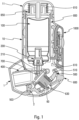
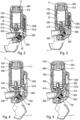
- This cover 1 is movable, preferably by being pivotally mounted on the body 10, between a closed position, visible on the figures 1 , 8 , 9 And 13 , and an opening position, visible on the Figures 2 to 7 , 14 and 15 .
- the valve 210 is fixed relative to the body 10, and it is the reservoir 100 which is moved axially relative to the body 10 between a distal position, which is the rest position, and a proximal position, which is the actuation position.
- valve 210 of said metering valve 200 is connected via a channel to said mouthpiece 400, through which the user inhales the dispensed product.
- said valve 210 is received in a valve well 700 which at least partially defines said channel.
- An actuating member 800 is advantageously assembled around the reservoir 100.
- This actuating member 800 comprises a hollow sleeve arranged in the body 10 around the reservoir 100.
- a thrust member 810 is mounted on the distal axial edge of said actuating member 800, said thrust member 810 being received in a cover element 11 fixed on the upper axial edge of said body 10.
- a spring 850 is arranged between a bottom of said cover element 11 and said thrust member 810. In the rest position, and until inhalation, the spring 850 is prestressed, and therefore exerts an axial force F on the thrust member 810 which transmits this force to the actuating member 800.
- the actuating member 800 is axially movable, in particular sliding, relative to said body 10 between a rest position and a position actuating member.
- a lower edge 802 of the actuating member 800 cooperates with the cover 1 such that in the closed position of the cover 1, said actuating member 800 is blocked in the rest position, the lower edge 802 abutting a part 3 of said cover 1.
- said cover 1 comprises a cam 4 which cooperates with said lower edge 802 when the cover 1 is returned from its open position to its closed position, to return said actuating member 800 from its actuating position to its rest position.
- the actuating member 800 returns to its rest position, it also returns the thrust member 810, which causes the compression of the spring 850.
- the spring 850 is therefore recharged after each actuation when the user closes the cover 1.
- the locking element 500 is advantageously pivotally mounted on the body 10 around an axis B (better visible in the Figures 16 to 18 ) between the blocking position and the actuating position.
- said blocking element 500 Before inhalation, said blocking element 500 is in the blocking position, and it is the user's inhalation through the mouthpiece 400 that moves and/or deforms said blocking element 500 to its actuating position.
- actuation of the metering valve 200 is impossible, and it is only when he inhales that said metering valve 200 can be actuated, by axial displacement of the reservoir 100 in the body 10.
- the blocking element 500 in the blocking position, prevents the axial movement of the actuating member 800 in the body 10.
- this blocking element 500 is moved and/or deformed such that it no longer blocks the axial movement of the actuating member 800 in the body 10.
- such an axial movement of the actuating member 800 causes the axial movement of the reservoir 100 and therefore the actuation of the metering valve 200 and the dispensing of a dose of product synchronized with this inhalation.
- a locking part 2 of the hood 1 cooperates with a projecting part 503 of the locking member 500 to lock the latter in the locking position, as visible in particular in the figure 1 .
- This blockage is removed when opening the cover 1.
- the device comprises a trigger system controlled by the user's inhalation, which is intended to move and/or deform said blocking element 500 from its blocking position to its actuating position, when the user inhales through the mouthpiece 400.
- This triggering system comprises an inhalation-sensitive member 60 which is deformable and/or movable under the effect of inhalation, this inhalation-sensitive member 60 being adapted, when it deforms and/or moves, to allow the movement and/or deformation of said blocking element 500 from its blocking position to its actuating position.
- the inhalation-responsive member may be embodied in the form of a deformable air chamber 60, for example a bellows or a deformable pocket.
- the inhalation-controlled triggering system is not located in the user's inhalation flow but is formed by a specific chamber, namely the air chamber 60.
- the system operates under vacuum and the user only sucks in the small volume of air that was inside the air chamber 60 before its deformation.
- the system according to the invention is thus much more stable and efficient.
- the locking element 500 comprises at least one, preferably two locking extensions 501, each of which cooperates in the locking position with an axial projection 801 of the actuating member 800.
- figure 29 represents a perspective view of this blocking element 500.
- each locking extension 501 moves out of contact with the axial projection 801 respectively.
- said locking element 500 comprises adjacent to each locking extension 501 an axial recess 502, visible on the figure 18 , in which the respective axial projection 801 can slide axially, thereby allowing axial sliding of said actuating member 800 in said body 10, causing axial displacement of the reservoir 100 and actuation of the valve 200 with the dispensing of a dose of fluid product.
- the locking element 500 is held in the locking position by a trigger element 600.
- figure 28 represents a perspective view of this trigger element 600.
- This trigger element 600 is advantageously pivotally mounted on the body 10 around an axis C (visible on the figures 16 And 18 ), between a locking position, in which it blocks said blocking element 500 in its blocking position, and a release position, in which it no longer blocks said blocking element 500.
- the B and C axes are parallel.
- the blocking element 500 and the trigger element 600 together define a lock.
- said trigger element 600 comprises a locking shoulder 610 which, in the locking position, cooperates with a locking projection 510 of the blocking element 500, preventing the pivoting of said blocking element 500 out of its locking position.
- said trigger element 600 when said trigger element 600 is in the locking position, it prevents the movement of the blocking element 500 towards its actuating position, which blocks the axial movement of the reservoir 100 and therefore the actuation of the metering valve 200.
- the blocking system of the present invention therefore comprises two stages: a first stage formed by the lock between the blocking element 500 and the trigger element 600, and a second stage formed by the blocking between the blocking element 500 and the actuating member 800.
- This locking system allows the unlocking of a large force (typically around 40-45N) by a small force generated by inhalation.
- the locking element 500 stops the translation of the actuating member 800 when it is subjected to a force F (of 45N for example) by the support of the spring 850 on the actuating member 800 via the pushing member 810.
- This blocking element 500 interacts with the trigger element 600 and is blocked/released by the latter. The movement of said trigger element 600 is controlled by inhalation.
- the geometry of the locking system allows for a very significant amplification (unlocked force/unlocking force), typically of the order of 100.
- the unlocking force generated by inhalation is applied to the trigger element 600 by the inhalation-sensitive member 60, preferably at a point 630 remote from the axis of the pivot C.
- This unlocking force unlocking aims to rotate said trigger element 600 in the direction S2 opposite to S1, as illustrated in the figure 17 .
- the torque that the blocking element 500 undergoes is controlled by the distance d between the force axis on which the force F is applied to the blocking extensions 501 of the blocking element and the pivot axis B of said blocking element 500.
- the aim is to have a distance d that is as small as possible in order to have the lowest possible torque.
- This distance d visible on the figure 16 , is non-zero, and is less than 2 mm, advantageously less than 1 mm.
- the torque that the trigger element 600 undergoes is controlled by the distance d' between the force axis carrying the force F' that the trigger element 600 undergoes from the blocking element 500 and the pivot axis C of said trigger element 600.
- a distance d' as small as possible in order to have the lowest possible torque.
- This distance d' visible on the figure 16 , is non-zero, and is less than 2 mm, advantageously less than 1 mm.
- the force required to pivot the trigger element 600 is very low and can be generated by the inhalation-sensitive member 60, which makes it possible to transform the depression generated by inhalation into unlocking force.
- the mouthpiece 400 comprises one or more openings 410 connected to the inside of the body 10.
- This at least one opening 410 is closed at rest and at the start of inhalation by a valve 420, such that the inhalation flow is initially mainly transmitted to the inhalation triggering system, in this example the deformable air chamber 60.
- the inhalation triggering system in this example the deformable air chamber 60.
- the blocking element 500 moves towards its actuating position under the effect of inhalation, and therefore the reservoir 100 moves axially relative to the body 10 to actuate the metering valve 200 to dispense a dose of fluid product
- said actuating member 800 or alternatively said reservoir 100, moves said valve 420 to an open position.
- the trigger element 600 can be accessible from outside the body 10. This allows, if necessary, the trigger element 600 to be moved manually, in order to be able to actuate the metering valve 200 even without inhalation, for example if the person to receive the dose of fluid product is unable to inhale sufficiently. This is therefore a safety feature. This also allows the valve to be primed, if it is a conventional valve requiring such priming.
- the inhalation-sensitive member 60 is made in the form of a deformable air chamber.
- this air chamber comprises a deformable membrane which is connected on the one hand to said body 10 and on the other hand to said trigger element 600.
- the membrane has a bellows shape and forms a substantially sealed chamber. Other shapes are possible, in particular a simple pocket or diaphragm.
- a stud can fix said membrane to an orifice or edge 630 of said trigger element 600.
- the deformable membrane deforms and/or contracts under the effect of the depression generated by inhalation, causing the trigger element 600 to move from its locking position to its release position. This makes it possible to open the lock defined between the blocking element 500 and the trigger element 600, and therefore to move said blocking element 500 from its blocking position to its actuating position.
- valve 200 is therefore only actuated at the time of inhalation, so that the dose of fluid product is expelled from the dispensing orifice simultaneously with inhalation.
- the thrust member 810 In the rest position, with the hood 1 closed, the thrust member 810 is not in contact with the tank 100, as visible in the figure 1 . Thus, in this position, the force of the spring 850 is applied by the thrust member 810 to the actuating member 800, which transmits it to the cover 1. Thus, during storage of the device, no stress is applied to the valve 200, which limits or even eliminates the risks of leaks and/or malfunction of said valve.
- the user When the user wishes to use the device, he opens the cover 1. In doing so, he removes the axial blocking of the actuating member 800 by the cover 1 as well as the pivoting blocking of the blocking element 500 by the cover 1. In this position, the actuating member 800 is blocked and prevented from sliding axially in the body 10 by the blocking extensions 501 of the blocking element 500 which axially block the axial projections 801 of the actuating member 800. As can be seen in the figure 2 , in this armed position (hood open, before inhalation), the thrust member 810 is still not in contact with the reservoir 100.
- the actuating member 800 (or alternatively the reservoir 100) will open the valve 420.
- the device advantageously includes signaling means to indicate to the user that he must close the cover 1.
- signaling means may include a visual indicator, as illustrated in the Figures 6 and 7 .
- a window 15 is formed in the body 10, through which a colored portion of the actuating member 800 is visible from the outside, forming indication means.
- the window 15 can indicate a light color, for example green, while after inhalation, it is a dark color, for example red which can be displayed in the window 15.
- a light color for example green
- red red
- the window (or windows) 15 may be positioned differently on the device, for example in the upper part of the body 10 or on the cover 11.
- the indication means which are displayed in the window 15 may alternatively comprise symbols, numbers, letters or any other useful indication to warn the user.
- These indication means may be formed, for example formed by pad printing, directly on the actuating member 800, or be formed on a part fixed thereto.
- the indication means may be made on any other part which moves during actuation, for example the pushing member 810, the blocking element 500, the trigger element 600, the inhalation-sensitive member 60.
- the signaling means may comprise an audible indicator, such as a loudspeaker, which emits a sound audible to the user to indicate to him that the cover 1 must be closed.
- an audible indicator such as a loudspeaker
- the actuating member 800 When the user closes the cover 1, the actuating member 800 is pushed axially by said cover 1 towards its rest position, so that said reservoir 100 can rise axially in the body 10 in the direction of its rest position under the effect of the return spring of the valve 200, and simultaneously the valve 210 of the metering valve returns to the rest position, loading a new dose of fluid product into the valve chamber.
- the trigger element 600 is returned to its initial position, in particular by the elasticity of the membrane.
- the blocking element 500 returns to its blocking position.
- the device is then ready for further use.
- the final assembly of the device is simplified for the pharmaceutical laboratory that markets the device. Indeed, in most existing devices, the reservoir filled with active ingredient is inserted into the body and then several parts must be positioned above the reservoir, which does not facilitate production rates and ease of assembly.
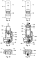
- the present invention advantageously provides for pre-assembling the subassembly formed by the thrust member 810, the spring 850 and the cover 11. This subassembly is pre-stressed during the assembly of these three parts, for example by using a hot tool O to thermally deform the lower axial edge 111 of a central axial sleeve 110 of the cover 11, around which the thrust member 810 and the spring 850 are assembled.
- Said lower axial edge 111 is thus deformed to produce a retention collar which retains the thrust member 810 and the spring 850 in the cover 11.
- This subassembly thus formed can then be assembled on the body 10 in a single assembly operation, for example by screwing or snapping. This then results in only two operations on the assembly line of the pharmaceutical laboratory: the insertion of the reservoir 100 into the body 10 ( figure 8 ) and the assembly of said subassembly on said body 10 ( figure 9 ).
- the actuating member 800 arranged in the body 10 will cooperate with the thrust member 810, to push it axially into the cover 11 and thus load the spring 850.
- this system can also allow the tank to be changed. Indeed, the device could be reusable and rechargeable for ecological reasons, in particular to avoid throwing away too many plastic components and/or too many electronic components.
- the device comprises an automatic valve release system, which automatically returns the valve 210 of the valve 200 to its rest position after actuation of the valve, independently of the position of the cover 1 and the position of the actuating member 800.
- an automatic valve release system which automatically returns the valve 210 of the valve 200 to its rest position after actuation of the valve, independently of the position of the cover 1 and the position of the actuating member 800.
- the thrust element 910 is intended to come into contact with the reservoir 100, and is connected to the thrust member 810, with the interposition of the lever spring 920.
- the thrust element 910 is very slightly offset axially from the reservoir 100, so that in this position, it does not transmit any stress to said reservoir 100 or to the valve 200. It is only when the user inhales, and releases the axial movement of the actuating member 800, that the thrust element 910 will come into contact with the reservoir 100.
- Each lever 901, 902 is assembled via studs 905 in a pivoting manner in a cam 815 of the thrust member 810 and cooperates with said thrust element 910.
- the valve release system therefore aims to release the transmission of the force from the spring 850 to the reservoir 100 after inhalation, to allow said reservoir 100 to return to its rest position independently of the actuating member 800. This makes it possible to load the next dose into the valve 200 immediately after inhalation, when the device is still in the appropriate position for this loading, without the risk of incorrect dosage, for example in the event of forgetting to close the cover 1.
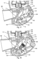
- this valve release system In locked position, before inhalation, visible on the figure 19 , the levers 901 and 902 are supported on a shoulder 911 of the thrust element 910. On the opposite side, the levers are in contact with locking fingers 115 formed in the cover 11 and which extend axially downwards from the bottom of said cover. These locking fingers 115 prevent the levers 901, 902 from pivoting out of contact with the shoulder 911 of the thrust element. In this position, the force of the spring 850 is therefore transmitted by the levers 901, 902 to the thrust element 910 and therefore to the tank 100.
- the pushing member 810, the pushing element 910 and the levers 901, 902 have slid axially downwards relative to the cover 11, as visible in the figure 20 .
- the levers 901, 902 no longer cooperate with the locking fingers 115 of the cover 11. They can then pivot in the thrust member 810 until they are no longer in contact with the shoulder 911 of the thrust element.
- the release of the thrust element 910 occurs after expulsion of the dose by the valve, but before the end of the actuation stroke of the latter.
- the valve release system must be actuated only after a sufficient stroke to ensure that the dose delivery occurs. Due to the manufacturing tolerances of the parts, it may be advantageous to provide a buffer element between the thrust element 910 and the reservoir 100.
- This buffer element which is to slow down or offset the actuation of the valve release system, may be an elastic element, such as a spring or a compressible part, for example made of elastomer. Its resistance must be on the one hand greater than the force of the spring of the valve 200 in the actuation position of the valve 210, so that it is first the valve 200 which is actuated.
- a buffer element formed by a cylinder or by a variable volume chamber, filled with air or a fluid, and provided with a leakage orifice could also be used.
- the device may comprise a dose counter 1000, shown in the Figures 1 to 9 , which may be mechanical or electronic, advantageously assembled in the body 10.
- a dose counter 1000 can in particular detect the movements of the actuating member 800 or of the reservoir 100.
- the counter could be connected to a sensor, in particular a membrane sensor, which detects the distribution of the dose of fluid product, for example in the valve well.
- Other means of actuating such a counter are also possible, for example the detection of the movement of the valve 210 of the metering valve 200 relative to the valve body.
- the meter When the meter is electronic, it must have enough electrical energy to operate throughout the storage period until its first use. The battery must then have sufficient capacity, for example to communicate with the user (display of the number of doses remaining) and/or with a third-party application, and this throughout its use and at least until the expiry date of the medication. To avoid an excessively large battery, the consumption of the electronic card must be reduced before the first use. To do this, the electronics are advantageously placed in a standby mode, which consumes little energy, until the time of the first use. To "wake up” the electronics, the user is asked to activate the device by inhaling the first dose (if the device is equipped with a valve without priming) or by priming (if the device is equipped with a conventional valve).
- the first actuation has the effect of lowering the actuating member 800 into the body 10. A portion of the actuating member 800 will then pressing a 1010 switch, as shown in the Figures 2 to 5 , which has the effect of closing a current loop. The device then detects this change in intensity, which will wake up the electronics and put the meter into normal operating condition.
- the device may include an accelerometer.
- the device may also include signal transmission means for communicating remotely, in particular information relating to the actuations of the device.
- the body and/or the cover and/or the meter may include a signal transmission module, for communicating remotely with any remote device. Suitable power supply means are advantageously provided.
- the electronic module may comprise a card comprising an electrical switch which sends a pulse.
- the module may also comprise a display and/or use a Bluetooth or Wifi connection to send the information to an ancillary device.
- Suitable sensors may be provided, such as flow and/or pressure sensors, to detect various parameters of the inhalation flow.
- the switch can be actuated by movement of the actuating member and/or the blocking element and/or the triggering element and/or the inhalation-sensitive member.
- these signal emitting means make it possible to transmit each dose distribution in an absolutely reliable manner, for example to a doctor or any other person wishing to monitor the use of the inhalation device by the user.
- the inhalation synchronization device ensures that the user inhales each time he activates the device, and the counter records each dose distributed, as well as various associated parameters, such as the time stamp of each distribution. The doctor can thus know very precisely the conditions of use of the device by the user.
- the present invention is particularly applicable for the treatment of asthma attacks or COPD (Chronic Obstructive Pulmonary Disease) in use with formulations of the salbutamol, aclidinium, formoterol, tiotropium, budesonide, fluticasone, indacaterol, glycopyrronium, salmeterol type, umeclidinium bromide, vilanterol, olodaterol, striverdi, or any combination of these formulations.
- COPD Choronic Obstructive Pulmonary Disease
Landscapes
- Health & Medical Sciences (AREA)
- Engineering & Computer Science (AREA)
- Life Sciences & Earth Sciences (AREA)
- Pulmonology (AREA)
- Animal Behavior & Ethology (AREA)
- Bioinformatics & Cheminformatics (AREA)
- Veterinary Medicine (AREA)
- Public Health (AREA)
- General Health & Medical Sciences (AREA)
- Heart & Thoracic Surgery (AREA)
- Biomedical Technology (AREA)
- Anesthesiology (AREA)
- Hematology (AREA)
- Chemical & Material Sciences (AREA)
- Medicinal Chemistry (AREA)
- Dispersion Chemistry (AREA)
- Mechanical Engineering (AREA)
- Chemical Kinetics & Catalysis (AREA)
- General Chemical & Material Sciences (AREA)
- Nuclear Medicine, Radiotherapy & Molecular Imaging (AREA)
- Organic Chemistry (AREA)
- Pharmacology & Pharmacy (AREA)
- Biophysics (AREA)
- Containers And Packaging Bodies Having A Special Means To Remove Contents (AREA)
- Closures For Containers (AREA)
Claims (20)
- Vorrichtung zur inhalationssynchronisierten Abgabe eines fluiden Produkts, umfassend einen Körper (10), der mit einem Mundstück (400) versehen ist, wobei ein Produktbehälter (100), der ein fluides Produkt und ein Treibgas enthält, in Bezug auf den Körper (10) axial verschiebbar montiert ist, wobei ein Dosierventil (200), das ein zwischen einer Ruhestellung und einer Betätigungsstellung bewegbares Ventilelement (210) umfasst, am Behälter (100) angebracht ist, um das fluide Produkt bei jeder Betätigung selektiv abzugeben, wobei die Vorrichtung Folgendes umfasst:- ein Blockierelement (500), das zwischen einer Blockierstellung, in der das Dosierventil (200) nicht betätigt werden kann, und einer Betätigungsstellung, in der das Dosierventil (200) betätigt werden kann, bewegbar und/oder verformbar ist,- ein Auslöseelement (600), das zwischen einer Verriegelungsstellung, in der es das Blockierelement (500) in seiner Blockierstellung blockiert, und einer Freigabestellung, in der es das Blockierelement (500) nicht blockiert, bewegbar und/oder verformbar ist,- ein durch die Inhalation gesteuertes Auslösesystem, das ein inhalationsempfindliches Organ (60) umfasst, das unter der Wirkung der Inhalation verformbar und/oder bewegbar ist, wobei das inhalationsempfindliche Organ (60) mit dem Auslöseelement (600) zusammenwirkt, sodass das inhalationsempfindliche Organ (60), wenn es sich verformt und/oder bewegt, das Auslöseelement (600) in seine Freigabestellung bewegt und/oder verformt, wodurch die Bewegung und/oder Verformung des Blockierelements (500) aus seiner Blockierstellung in seine Betätigungsstellung ermöglicht wird,- ein Betätigungsorgan (800), das unter der Wirkung einer Feder (850) zwischen einer Ruhestellung und einer Betätigungsstellung bewegbar ist, wobei das Betätigungsorgan (800) mit dem Blockierelement (500) zusammenwirkt, sodass das Blockierelement (500) in der Blockierstellung des Blockierelements (500) eine axiale Bewegung des Betätigungsorgans (800) verhindert und das Blockierelement (500) in der Betätigungsstellung des Blockierelements (500) eine axiale Bewegung des Betätigungsorgans (800) zulässt, und- einen Dosenzähler (1000), wobei das Blockierelement (500) einen Verriegelungsvorsprung (510) umfasst, der in der Verriegelungsstellung des Auslöseelements (600), mit einer Verriegelungsschulter (610) des Auslöseelements (600) zusammenwirkt, um ein Schloss zu definieren, das die Bewegung und/oder die Verformung des Blockierelements (500) aus seiner Blockierstellung heraus verhindert,dadurch gekennzeichnet, dass die Vorrichtung ein automatisches Ventilfreigabesystem umfasst, das das Ventilelement (210) des Ventils (200) nach der Betätigung des Ventils unabhängig von der Stellung des Betätigungsorgans (800) automatisch in seine Ruhestellung zurückführt.
- Vorrichtung nach Anspruch 1, wobei die Vorrichtung eine Abdeckung (1) umfasst, die zwischen einer Schließstellung des Mundstücks (400) und einer Öffnungsstellung des Mundstücks (400) bewegbar ist, insbesondere am Körper (10) schwenkbar, wobei die Abdeckung (1) mit dem Betätigungsorgan (800) so zusammenwirkt, dass sie in der Schließstellung das Betätigungsorgan (800) gegen eine axiale Bewegung im Körper (10) blockiert und das sie, wenn sie aus ihrer Öffnungsstellung in ihre Schließstellung zurückgeführt wird, das Betätigungsorgan (800) in seine Ruhestellung zurückführt und dabei die Feder (850) wieder belastet.
- Vorrichtung nach Anspruch 2, wobei das automatische Ventilfreigabesystemelement zwei Hebel (901, 902), ein Schubelement (910) und eine Hebelfeder (920) umfasst, wobei das Schubelement (910) dazu bestimmt ist, mit dem Behälter (100) in Kontakt zu kommen, wobei das Schubelement (910) unter Zwischenschaltung der Hebelfeder (920) mit einem Schuborgan (810) verbunden ist.
- Vorrichtung nach Anspruch 3, wobei jeder Hebel (901, 902) über Noppen (905) schwenkbar in einem Nocken (815) des Schuborgans (810) angebracht ist und mit dem Schubelement (910) zusammenwirkt, um die durch die Feder (850) ausgeübte Kraft (F) auf das Schubelement (910) zu übertragen.
- Vorrichtung nach Anspruch 4, wobei die Hebel (901, 902) in der Verriegelungsstellung vor der Inhalation auf einer Seite an einer Schulter (911) des Schubelements (910) anliegen und wobei die Hebel (901, 902) auf der anderen Seite mit Verriegelungsfingern (115) in Kontakt stehen, die in einem Deckel (11) ausgebildet sind und die sich vom Boden des Deckels (11) axial nach unten erstrecken, wobei die Verriegelungsfinger (115) verhindern, dass sich die Hebel (901, 902) aus dem Kontakt mit der Schulter (911) des Schubelements (910) herausschwenken.
- Vorrichtung nach Anspruch 5, wobei die Hebel (901, 902) in der Betätigungsstellung nach der Inhalation nicht mehr mit den Verriegelungsfingern (115) des Deckels (11) zusammenwirken, sodass sie dann im Schuborgan (810) aus dem Kontakt mit der Schulter (911) des Schubelements (910) herausschwenken können, sodass der Behälter (100) unter der Wirkung der Rückstellfeder des Ventils (200) in seine Ruhestellung zurückkehren kann, wobei die Hebel (901, 902) durch Löcher (912) des Schubelements (910) hindurchlaufen.
- Vorrichtung nach Anspruch 6, wobei das Betätigungsorgan (800) und das Schuborgan (810) beim Zurücksetzen der Vorrichtung, wenn der Benutzer die Abdeckung (1) wieder schließt, in ihre Ruhestellungen zurückkehren, wobei die Feder (850) zusammengedrückt wird und die Hebel (901, 902) sich zusammen mit dem Schuborgan (810) axial bewegen, bis sie mit den Verriegelungsfingern (115) des Deckels (11) in Kontakt kommen, die die Noppen (905) dazu drängen, sich in den Nocken (815) radial nach außen zu bewegen, wodurch die Hebel (901, 902) um die Verriegelungsfinger (115) herum zurückkehren können, wobei die Hebelfeder (920) dann die Hebel (901, 902) in Anlage an der Schulter (911) des Schubelements (910) zurückbringt.
- Vorrichtung nach einem der vorangehenden Ansprüche, wobei das Blockierelement (500) um eine Schwenkachse (B) schwenkbar am Körper (10) montiert ist und das Auslöseelement (600) um eine Schwenkachse (C) schwenkbar am Körper (10) montiert ist, wobei die Achsen (B) und (C) parallel sind.
- Vorrichtung nach einem der vorangehenden Ansprüche, wobei das Betätigungsorgan (800) einen axialen Vorsprung (801) umfasst, der mit dem Blockierelement (500) zusammenwirkt, so dass der axiale Vorsprung (801) des Betätigungsorgans (800) in der Blockierstellung des Blockierelements (500) mit einer axialen Blockiererstreckung (501) des Blockierelements (500) zusammenwirkt, um so eine axiale Bewegung des Betätigungsorgans (800) zu verhindern, und wobei der axiale Vorsprung (801) des Betätigungsorgans (800) in der Betätigungsstellung des Blockierelements (500) mit einer axialen Aussparung (502) des Blockierelements (500) zusammenwirkt, um so eine axiale Bewegung des Betätigungsorgans (800) zuzulassen.
- Vorrichtung nach Anspruch 9, wobei der axiale Vorsprung (801) des Betätigungsorgans (800) in der Blockierstellung des Blockierelements (500) das Blockierelement (500) in seine Betätigungsstellung drängt.
- Vorrichtung nach einem der vorangehenden Ansprüche, wobei das Schloss in der Verriegelungsstellung des Auslöseelements (600) einen ersten Kontaktpunkt zwischen dem Blockierelement (500) und dem Auslöseelement (600) ausbildet, wobei das Blockierelement (500) einen Auflagevorsprung (520) umfasst, der in der Verriegelungsstellung des Auslöseelements (600) mit einer Auflagefläche (620) des Auslöseelements (600) zusammenwirkt, um in der Verriegelungsstellung des Auslöseelements (600), einen zweiten Kontaktpunkt zwischen dem Blockierelement (500) und dem Auslöseelement (600) auszubilden, wobei sich der zweite Kontaktpunkt in der Verriegelungsstellung des Auslöseelements (600) in einem Abstand zur Achse (C) des Auslöseelements (600) befindet, der größer als der Abstand zwischen der Achse (C) und dem ersten Kontaktpunkt ist.
- Vorrichtung nach einem der vorangehenden Ansprüche, wobei die Vorrichtung Folgendes umfasst:- einen Deckel (11), der auf dem Körper (10) befestigt, insbesondere aufgeschraubt oder aufgerastet ist, und- ein Schuborgan (810), das mit dem Betätigungsorgan (800) zusammenwirkt und axial verschiebbar im Deckel (11) montiert ist, wobei die Feder (850) zwischen einem Boden des Deckels (11) und dem Schuborgan (810) angeordnet ist,wobei das Schuborgan (810) vor der Inhalation außer Kontakt mit dem Behälter (100) steht, sodass die durch die Feder (850) auf das Schuborgan (810) ausgeübte Kraft nicht auf den Behälter (100) übertragen wird, und wobei sich das Schuborgan (810) während der Inhalation zusammen mit dem Betätigungsorgan (800) axial bewegt, um mit dem Behälter (100) in Kontakt zu kommen und den Behälter (100) axial im Körper (10) zu bewegen, um das Ventil (200) zu betätigen.
- Vorrichtung nach einem der vorangehenden Ansprüche, umfassend einen Indikator (15), um dem Benutzer anzuzeigen, dass die Abgabe eines fluiden Produkts erfolgt ist.
- Vorrichtung nach Anspruch 13, wobei es sich bei dem Indikator um einen visuellen und/oder akustischen Indikator handelt.
- Vorrichtung nach einem der vorangehenden Ansprüche, wobei es sich bei dem Dosenzähler (1000) um einen elektronischen Zähler handelt.
- Vorrichtung nach Anspruch 15, wobei sich der elektronische Zähler (1000) vor der ersten Verwendung der Vorrichtung im Bereitschaftsmodus befindet, wobei der elektronische Zähler einen Kontaktgeber (1010) umfasst, wobei das Betätigungsorgan (800) bei seiner ersten Bewegung in seine Betätigungsstellung mit dem Kontaktgeber (1010) in Kontakt kommt, um den elektronischen Zähler (1000) in den Normalbetriebsmodus zu versetzen.
- Vorrichtung nach Anspruch 15 oder 16, wobei der elektronische Zähler (1000) mindestens einen Beschleunigungsmesser umfasst.
- Vorrichtung nach einem der vorangehenden Ansprüche, wobei das inhalationsempfindliche Organ (60) eine verformbare Membran umfasst, die eine verformbare Luftkammer definiert, wobei die verformbare Membran am Auslöseelement (600) befestigt ist, wobei die verformbare Membran während der Inhalation so verformt wird, dass sie das Auslöseelement (600) aus seiner Verriegelungsstellung in seine Freigabestellung bewegt.
- Vorrichtung nach einem der vorangehenden Ansprüche, wobei das Mundstück (400) eine Öffnung (410) umfasst, die mit dem Inneren des Körpers (10) verbunden ist, wobei die Öffnung (410) zu Beginn der Inhalation durch eine Klappe (420) verschlossen ist, sodass der Inhalationsstrom anfangs hauptsächlich an das Inhalationsauslösesystem weitergeleitet wird.
- Vorrichtung nach Anspruch 19, wobei die Klappe (420) offen ist, wenn sich das Betätigungsorgan (800) zusammen mit dem Behälter (100) axial bewegt.
Applications Claiming Priority (2)
| Application Number | Priority Date | Filing Date | Title |
|---|---|---|---|
| FR1901076A FR3092250B1 (fr) | 2019-02-04 | 2019-02-04 | Dispositif de distribution de produit fluide synchronisé avec l'inhalation |
| PCT/FR2020/050170 WO2020161420A1 (fr) | 2019-02-04 | 2020-02-03 | Dispositif de distribution de produit fluide synchronise avec l'inhalation |
Publications (2)
| Publication Number | Publication Date |
|---|---|
| EP3921002A1 EP3921002A1 (de) | 2021-12-15 |
| EP3921002B1 true EP3921002B1 (de) | 2024-11-20 |
Family
ID=67185261
Family Applications (1)
| Application Number | Title | Priority Date | Filing Date |
|---|---|---|---|
| EP20706793.5A Active EP3921002B1 (de) | 2019-02-04 | 2020-02-03 | Vorrichtung zur inhalationssynchronisierten abgabe eines flüssigen produkts |
Country Status (6)
| Country | Link |
|---|---|
| US (1) | US12186480B2 (de) |
| EP (1) | EP3921002B1 (de) |
| JP (1) | JP7463384B2 (de) |
| CN (1) | CN113382760B (de) |
| FR (1) | FR3092250B1 (de) |
| WO (1) | WO2020161420A1 (de) |
Families Citing this family (5)
| Publication number | Priority date | Publication date | Assignee | Title |
|---|---|---|---|---|
| USD1006214S1 (en) * | 2020-02-14 | 2023-11-28 | Aptar France Sas | Inhaler |
| USD995752S1 (en) * | 2020-02-14 | 2023-08-15 | Aptar France Sas | Inhaler |
| USD1006213S1 (en) * | 2020-02-14 | 2023-11-28 | Aptar France Sas | Inhaler |
| USD983961S1 (en) * | 2020-02-14 | 2023-04-18 | Aptar France Sas | Inhaler |
| IL316077B2 (en) * | 2024-10-01 | 2025-06-01 | Stav Iyar | A dispensing device for solid objects |
Citations (1)
| Publication number | Priority date | Publication date | Assignee | Title |
|---|---|---|---|---|
| WO2019170718A1 (en) * | 2018-03-07 | 2019-09-12 | Astrazeneca Ab | Inhaler |
Family Cites Families (33)
| Publication number | Priority date | Publication date | Assignee | Title |
|---|---|---|---|---|
| US3456646A (en) | 1967-01-19 | 1969-07-22 | Dart Ind Inc | Inhalation-actuated aerosol dispensing device |
| US5119806A (en) | 1987-05-12 | 1992-06-09 | Glaxo Inc. | Inhalation device |
| US5060643A (en) * | 1990-08-07 | 1991-10-29 | Tenax Corporation | Breath-activated inhalation device |
| US5622163A (en) * | 1994-11-29 | 1997-04-22 | Iep Group, Inc. | Counter for fluid dispensers |
| US6082358A (en) * | 1998-05-05 | 2000-07-04 | 1263152 Ontario Inc. | Indicating device for aerosol container |
| FR2817247B1 (fr) * | 2000-11-24 | 2003-02-14 | Valois Sa | Dispositif de distribution de produit fluide |
| FR2834277B1 (fr) | 2001-12-28 | 2004-06-11 | Valois Sa | Dispositif de distribution de produit fluide |
| GB0315791D0 (en) * | 2003-07-07 | 2003-08-13 | 3M Innovative Properties Co | Two component molded valve stems |
| GB0222295D0 (en) | 2002-09-25 | 2002-10-30 | 3M Innovative Properties Co | Breath actuated medicament dispensing devices |
| GB2398065A (en) * | 2003-10-16 | 2004-08-11 | Bespak Plc | Dispensing apparatus |
| US7219664B2 (en) | 2005-04-28 | 2007-05-22 | Kos Life Sciences, Inc. | Breath actuated inhaler |
| JP2008539912A (ja) * | 2005-05-10 | 2008-11-20 | バング アンド オルフセン メディコム アーエス | 前進式計量弁 |
| GB0518355D0 (en) * | 2005-09-08 | 2005-10-19 | Glaxo Group Ltd | An inhaler |
| FR2904228B1 (fr) * | 2006-07-25 | 2009-05-29 | Valois Sas | Dispositif de distribution de produit fluide. |
| WO2008070516A2 (en) | 2006-12-01 | 2008-06-12 | Abbott Laboratories | Dose selective breath actuated inhaler |
| US8225790B2 (en) | 2007-01-02 | 2012-07-24 | Astrazeneca Ab | Inhaler 624 |
| ES2423587T3 (es) | 2008-07-10 | 2013-09-23 | Bang & Olufsen Medicom A/S | Inhalador y procedimiento de operación del mismo |
| US8469030B2 (en) * | 2009-12-01 | 2013-06-25 | Covidien Lp | Exhalation valve assembly with selectable contagious/non-contagious latch |
| EP2557986A4 (de) | 2010-04-11 | 2014-01-22 | Proteus Digital Health Inc | Vorrichtung, system und verfahren zur erkennung und verabreichung einer medizinischen dosis |
| EP2740508B1 (de) * | 2011-08-16 | 2016-06-15 | PAX Labs, Inc. | Elektronische Verdampfungsvorrichtung mit niedriger Temperatur |
| FR2991185B1 (fr) | 2012-05-31 | 2015-06-26 | Valois Sas | Dispositif de distribution de produit fluide. |
| CA2900326A1 (en) * | 2013-02-06 | 2014-08-14 | Flextronics Ap, Llc | Metered dose inhaler with an electronic dose counter |
| US8807131B1 (en) * | 2013-06-18 | 2014-08-19 | Isonea Limited | Compliance monitoring for asthma inhalers |
| US20160106935A1 (en) * | 2014-10-17 | 2016-04-21 | Qualcomm Incorporated | Breathprint sensor systems, smart inhalers and methods for personal identification |
| CA2968361A1 (en) * | 2014-11-20 | 2016-05-26 | Cognita Labs, LLC | Method and apparatus to measure, aid and correct the use of inhalers |
| US20160144142A1 (en) * | 2014-11-24 | 2016-05-26 | Jeff Baker | Metered dose respiratory training device and system |
| WO2017112451A1 (en) * | 2015-12-21 | 2017-06-29 | 3M Innovative Properties Company | Auto-reset dose release firing systems, medicinal inhalers comprising same, and methods of using same |
| EP3439721B1 (de) * | 2016-04-05 | 2021-12-08 | Kindeva Drug Delivery L.P. | Medizinischer inhalator mit einer nachfüllanordnung umfassend einen sperrmechanismus |
| FR3050115B1 (fr) * | 2016-04-15 | 2023-05-12 | Aptar France Sas | Dispositif de distribution de produit fluide synchronise avec l'inhalation. |
| WO2017182975A1 (en) * | 2016-04-22 | 2017-10-26 | Resolve Digital Health Inc. | An inhalation device, system and method |
| GB201615185D0 (en) * | 2016-09-07 | 2016-10-19 | 3M Innovative Properties Co | Reset mechanism for an inhaler |
| US11344685B2 (en) * | 2016-11-18 | 2022-05-31 | Norton (Waterford) Limited | Drug delivery device with electronics |
| GB201702406D0 (en) * | 2017-02-14 | 2017-03-29 | Norton (Waterford) Ltd | Inhalers and related methods |
-
2019
- 2019-02-04 FR FR1901076A patent/FR3092250B1/fr active Active
-
2020
- 2020-02-03 US US17/427,682 patent/US12186480B2/en active Active
- 2020-02-03 JP JP2021545425A patent/JP7463384B2/ja active Active
- 2020-02-03 CN CN202080012422.4A patent/CN113382760B/zh active Active
- 2020-02-03 WO PCT/FR2020/050170 patent/WO2020161420A1/fr not_active Ceased
- 2020-02-03 EP EP20706793.5A patent/EP3921002B1/de active Active
Patent Citations (1)
| Publication number | Priority date | Publication date | Assignee | Title |
|---|---|---|---|---|
| WO2019170718A1 (en) * | 2018-03-07 | 2019-09-12 | Astrazeneca Ab | Inhaler |
Also Published As
| Publication number | Publication date |
|---|---|
| FR3092250B1 (fr) | 2021-01-22 |
| FR3092250A1 (fr) | 2020-08-07 |
| CN113382760B (zh) | 2022-11-15 |
| US20220126037A1 (en) | 2022-04-28 |
| JP2022519602A (ja) | 2022-03-24 |
| CN113382760A (zh) | 2021-09-10 |
| EP3921002A1 (de) | 2021-12-15 |
| JP7463384B2 (ja) | 2024-04-08 |
| BR112021015344A2 (pt) | 2021-09-28 |
| US12186480B2 (en) | 2025-01-07 |
| WO2020161420A1 (fr) | 2020-08-13 |
Similar Documents
| Publication | Publication Date | Title |
|---|---|---|
| EP4100088B1 (de) | Vorrichtung zur ausgabe eines mit inhalation synchronisierten flüssigproduktes und verfahren zum zusammenbau dieser vorrichtung | |
| EP3921002B1 (de) | Vorrichtung zur inhalationssynchronisierten abgabe eines flüssigen produkts | |
| EP3921003B1 (de) | Vorrichtung zur inhalationssynchronisierten abgabe eines flüssigen produkts | |
| EP3442630B1 (de) | Vorrichtung zur inhalationssynchronisierten ausgabe eines flüssigprodukts | |
| EP3442631B1 (de) | Vorrichtung zur inhalationssynchronisierten ausgabe eines flüssigprodukts | |
| EP3442632B1 (de) | Vorrichtung zur abgabe eines flüssigen produktes mit inhalationssynchronisation | |
| EP3220985B1 (de) | Inhalationsbetätigte abgabevorrichtung für ein flüssiges produkt. | |
| EP3661578A1 (de) | Spender für ein flüssigprodukt | |
| EP3697483B1 (de) | Vorrichtung zur inhalationssynchronisierten abgabe eines flüssigen produkts | |
| EP3697482B1 (de) | Vorrichtung zur inhalationssynchronisierten abgabe eines flüssigen produkts | |
| EP3717048B1 (de) | Vorrichtung zur inhalationssynchronisierten ausgabe eines flüssigprodukts | |
| EP3886952B1 (de) | Vorrichtung zur inhalationssynchronisierten ausgabe eines flüssigprodukts |
Legal Events
| Date | Code | Title | Description |
|---|---|---|---|
| STAA | Information on the status of an ep patent application or granted ep patent |
Free format text: STATUS: UNKNOWN |
|
| STAA | Information on the status of an ep patent application or granted ep patent |
Free format text: STATUS: THE INTERNATIONAL PUBLICATION HAS BEEN MADE |
|
| PUAI | Public reference made under article 153(3) epc to a published international application that has entered the european phase |
Free format text: ORIGINAL CODE: 0009012 |
|
| STAA | Information on the status of an ep patent application or granted ep patent |
Free format text: STATUS: REQUEST FOR EXAMINATION WAS MADE |
|
| 17P | Request for examination filed |
Effective date: 20210827 |
|
| AK | Designated contracting states |
Kind code of ref document: A1 Designated state(s): AL AT BE BG CH CY CZ DE DK EE ES FI FR GB GR HR HU IE IS IT LI LT LU LV MC MK MT NL NO PL PT RO RS SE SI SK SM TR |
|
| DAV | Request for validation of the european patent (deleted) | ||
| DAX | Request for extension of the european patent (deleted) | ||
| STAA | Information on the status of an ep patent application or granted ep patent |
Free format text: STATUS: EXAMINATION IS IN PROGRESS |
|
| 17Q | First examination report despatched |
Effective date: 20220826 |
|
| GRAP | Despatch of communication of intention to grant a patent |
Free format text: ORIGINAL CODE: EPIDOSNIGR1 |
|
| STAA | Information on the status of an ep patent application or granted ep patent |
Free format text: STATUS: GRANT OF PATENT IS INTENDED |
|
| INTG | Intention to grant announced |
Effective date: 20240620 |
|
| RIN1 | Information on inventor provided before grant (corrected) |
Inventor name: WALTER, MATTHIEU Inventor name: TOURNOIS, JEREMY Inventor name: CAVATORTA, MATTHIEU Inventor name: FABIEN, DAVID |
|
| GRAS | Grant fee paid |
Free format text: ORIGINAL CODE: EPIDOSNIGR3 |
|
| GRAA | (expected) grant |
Free format text: ORIGINAL CODE: 0009210 |
|
| STAA | Information on the status of an ep patent application or granted ep patent |
Free format text: STATUS: THE PATENT HAS BEEN GRANTED |
|
| P01 | Opt-out of the competence of the unified patent court (upc) registered |
Free format text: CASE NUMBER: APP_53060/2024 Effective date: 20240923 |
|
| AK | Designated contracting states |
Kind code of ref document: B1 Designated state(s): AL AT BE BG CH CY CZ DE DK EE ES FI FR GB GR HR HU IE IS IT LI LT LU LV MC MK MT NL NO PL PT RO RS SE SI SK SM TR |
|
| REG | Reference to a national code |
Ref country code: GB Ref legal event code: FG4D Free format text: NOT ENGLISH |
|
| REG | Reference to a national code |
Ref country code: CH Ref legal event code: EP |
|
| REG | Reference to a national code |
Ref country code: DE Ref legal event code: R096 Ref document number: 602020041606 Country of ref document: DE |
|
| REG | Reference to a national code |
Ref country code: IE Ref legal event code: FG4D Free format text: LANGUAGE OF EP DOCUMENT: FRENCH |
|
| REG | Reference to a national code |
Ref country code: LT Ref legal event code: MG9D |
|
| REG | Reference to a national code |
Ref country code: NL Ref legal event code: MP Effective date: 20241120 |
|
| PG25 | Lapsed in a contracting state [announced via postgrant information from national office to epo] |
Ref country code: HR Free format text: LAPSE BECAUSE OF FAILURE TO SUBMIT A TRANSLATION OF THE DESCRIPTION OR TO PAY THE FEE WITHIN THE PRESCRIBED TIME-LIMIT Effective date: 20241120 Ref country code: IS Free format text: LAPSE BECAUSE OF FAILURE TO SUBMIT A TRANSLATION OF THE DESCRIPTION OR TO PAY THE FEE WITHIN THE PRESCRIBED TIME-LIMIT Effective date: 20250320 Ref country code: PT Free format text: LAPSE BECAUSE OF FAILURE TO SUBMIT A TRANSLATION OF THE DESCRIPTION OR TO PAY THE FEE WITHIN THE PRESCRIBED TIME-LIMIT Effective date: 20250320 |
|
| PG25 | Lapsed in a contracting state [announced via postgrant information from national office to epo] |
Ref country code: FI Free format text: LAPSE BECAUSE OF FAILURE TO SUBMIT A TRANSLATION OF THE DESCRIPTION OR TO PAY THE FEE WITHIN THE PRESCRIBED TIME-LIMIT Effective date: 20241120 Ref country code: NL Free format text: LAPSE BECAUSE OF FAILURE TO SUBMIT A TRANSLATION OF THE DESCRIPTION OR TO PAY THE FEE WITHIN THE PRESCRIBED TIME-LIMIT Effective date: 20241120 |
|
| REG | Reference to a national code |
Ref country code: AT Ref legal event code: MK05 Ref document number: 1743018 Country of ref document: AT Kind code of ref document: T Effective date: 20241120 |
|
| PG25 | Lapsed in a contracting state [announced via postgrant information from national office to epo] |
Ref country code: BG Free format text: LAPSE BECAUSE OF FAILURE TO SUBMIT A TRANSLATION OF THE DESCRIPTION OR TO PAY THE FEE WITHIN THE PRESCRIBED TIME-LIMIT Effective date: 20241120 |
|
| PG25 | Lapsed in a contracting state [announced via postgrant information from national office to epo] |
Ref country code: ES Free format text: LAPSE BECAUSE OF FAILURE TO SUBMIT A TRANSLATION OF THE DESCRIPTION OR TO PAY THE FEE WITHIN THE PRESCRIBED TIME-LIMIT Effective date: 20241120 |
|
| PG25 | Lapsed in a contracting state [announced via postgrant information from national office to epo] |
Ref country code: NO Free format text: LAPSE BECAUSE OF FAILURE TO SUBMIT A TRANSLATION OF THE DESCRIPTION OR TO PAY THE FEE WITHIN THE PRESCRIBED TIME-LIMIT Effective date: 20250220 |
|
| PG25 | Lapsed in a contracting state [announced via postgrant information from national office to epo] |
Ref country code: GR Free format text: LAPSE BECAUSE OF FAILURE TO SUBMIT A TRANSLATION OF THE DESCRIPTION OR TO PAY THE FEE WITHIN THE PRESCRIBED TIME-LIMIT Effective date: 20250221 Ref country code: AT Free format text: LAPSE BECAUSE OF FAILURE TO SUBMIT A TRANSLATION OF THE DESCRIPTION OR TO PAY THE FEE WITHIN THE PRESCRIBED TIME-LIMIT Effective date: 20241120 Ref country code: LV Free format text: LAPSE BECAUSE OF FAILURE TO SUBMIT A TRANSLATION OF THE DESCRIPTION OR TO PAY THE FEE WITHIN THE PRESCRIBED TIME-LIMIT Effective date: 20241120 |
|
| PG25 | Lapsed in a contracting state [announced via postgrant information from national office to epo] |
Ref country code: PL Free format text: LAPSE BECAUSE OF FAILURE TO SUBMIT A TRANSLATION OF THE DESCRIPTION OR TO PAY THE FEE WITHIN THE PRESCRIBED TIME-LIMIT Effective date: 20241120 |
|
| PG25 | Lapsed in a contracting state [announced via postgrant information from national office to epo] |
Ref country code: RS Free format text: LAPSE BECAUSE OF FAILURE TO SUBMIT A TRANSLATION OF THE DESCRIPTION OR TO PAY THE FEE WITHIN THE PRESCRIBED TIME-LIMIT Effective date: 20250220 |
|
| PG25 | Lapsed in a contracting state [announced via postgrant information from national office to epo] |
Ref country code: SM Free format text: LAPSE BECAUSE OF FAILURE TO SUBMIT A TRANSLATION OF THE DESCRIPTION OR TO PAY THE FEE WITHIN THE PRESCRIBED TIME-LIMIT Effective date: 20241120 |
|
| PG25 | Lapsed in a contracting state [announced via postgrant information from national office to epo] |
Ref country code: DK Free format text: LAPSE BECAUSE OF FAILURE TO SUBMIT A TRANSLATION OF THE DESCRIPTION OR TO PAY THE FEE WITHIN THE PRESCRIBED TIME-LIMIT Effective date: 20241120 |
|
| PG25 | Lapsed in a contracting state [announced via postgrant information from national office to epo] |
Ref country code: EE Free format text: LAPSE BECAUSE OF FAILURE TO SUBMIT A TRANSLATION OF THE DESCRIPTION OR TO PAY THE FEE WITHIN THE PRESCRIBED TIME-LIMIT Effective date: 20241120 |
|
| PG25 | Lapsed in a contracting state [announced via postgrant information from national office to epo] |
Ref country code: RO Free format text: LAPSE BECAUSE OF FAILURE TO SUBMIT A TRANSLATION OF THE DESCRIPTION OR TO PAY THE FEE WITHIN THE PRESCRIBED TIME-LIMIT Effective date: 20241120 |
|
| PG25 | Lapsed in a contracting state [announced via postgrant information from national office to epo] |
Ref country code: SK Free format text: LAPSE BECAUSE OF FAILURE TO SUBMIT A TRANSLATION OF THE DESCRIPTION OR TO PAY THE FEE WITHIN THE PRESCRIBED TIME-LIMIT Effective date: 20241120 |
|
| PG25 | Lapsed in a contracting state [announced via postgrant information from national office to epo] |
Ref country code: CZ Free format text: LAPSE BECAUSE OF FAILURE TO SUBMIT A TRANSLATION OF THE DESCRIPTION OR TO PAY THE FEE WITHIN THE PRESCRIBED TIME-LIMIT Effective date: 20241120 |
|
| REG | Reference to a national code |
Ref country code: DE Ref legal event code: R097 Ref document number: 602020041606 Country of ref document: DE |
|
| PG25 | Lapsed in a contracting state [announced via postgrant information from national office to epo] |
Ref country code: SE Free format text: LAPSE BECAUSE OF FAILURE TO SUBMIT A TRANSLATION OF THE DESCRIPTION OR TO PAY THE FEE WITHIN THE PRESCRIBED TIME-LIMIT Effective date: 20241120 |
|
| PG25 | Lapsed in a contracting state [announced via postgrant information from national office to epo] |
Ref country code: MC Free format text: LAPSE BECAUSE OF FAILURE TO SUBMIT A TRANSLATION OF THE DESCRIPTION OR TO PAY THE FEE WITHIN THE PRESCRIBED TIME-LIMIT Effective date: 20241120 |
|
| PLBE | No opposition filed within time limit |
Free format text: ORIGINAL CODE: 0009261 |
|
| STAA | Information on the status of an ep patent application or granted ep patent |
Free format text: STATUS: NO OPPOSITION FILED WITHIN TIME LIMIT |
|
| REG | Reference to a national code |
Ref country code: CH Ref legal event code: PL |
|
| PG25 | Lapsed in a contracting state [announced via postgrant information from national office to epo] |
Ref country code: LU Free format text: LAPSE BECAUSE OF NON-PAYMENT OF DUE FEES Effective date: 20250203 |
|
| PG25 | Lapsed in a contracting state [announced via postgrant information from national office to epo] |
Ref country code: CH Free format text: LAPSE BECAUSE OF NON-PAYMENT OF DUE FEES Effective date: 20250228 |
|
| 26N | No opposition filed |
Effective date: 20250821 |
|
| REG | Reference to a national code |
Ref country code: BE Ref legal event code: MM Effective date: 20250228 |
|
| PG25 | Lapsed in a contracting state [announced via postgrant information from national office to epo] |
Ref country code: BE Free format text: LAPSE BECAUSE OF NON-PAYMENT OF DUE FEES Effective date: 20250228 |
|
| PG25 | Lapsed in a contracting state [announced via postgrant information from national office to epo] |
Ref country code: IE Free format text: LAPSE BECAUSE OF NON-PAYMENT OF DUE FEES Effective date: 20250203 |
|
| PGFP | Annual fee paid to national office [announced via postgrant information from national office to epo] |
Ref country code: GB Payment date: 20260219 Year of fee payment: 7 |
|
| PGFP | Annual fee paid to national office [announced via postgrant information from national office to epo] |
Ref country code: DE Payment date: 20260206 Year of fee payment: 7 |
|
| PGFP | Annual fee paid to national office [announced via postgrant information from national office to epo] |
Ref country code: IT Payment date: 20260209 Year of fee payment: 7 |
|
| PGFP | Annual fee paid to national office [announced via postgrant information from national office to epo] |
Ref country code: FR Payment date: 20260227 Year of fee payment: 7 |