EP3442809B1 - Interface de fente couplée de façon fixe à un cadre - Google Patents
Interface de fente couplée de façon fixe à un cadre Download PDFInfo
- Publication number
- EP3442809B1 EP3442809B1 EP16898831.9A EP16898831A EP3442809B1 EP 3442809 B1 EP3442809 B1 EP 3442809B1 EP 16898831 A EP16898831 A EP 16898831A EP 3442809 B1 EP3442809 B1 EP 3442809B1
- Authority
- EP
- European Patent Office
- Prior art keywords
- frame
- bracket
- slot interface
- device module
- panel portion
- Prior art date
- Legal status (The legal status is an assumption and is not a legal conclusion. Google has not performed a legal analysis and makes no representation as to the accuracy of the status listed.)
- Not-in-force
Links
Images




Classifications
-
- B—PERFORMING OPERATIONS; TRANSPORTING
- B41—PRINTING; LINING MACHINES; TYPEWRITERS; STAMPS
- B41J—TYPEWRITERS; SELECTIVE PRINTING MECHANISMS, i.e. MECHANISMS PRINTING OTHERWISE THAN FROM A FORME; CORRECTION OF TYPOGRAPHICAL ERRORS
- B41J29/00—Details of, or accessories for, typewriters or selective printing mechanisms not otherwise provided for
- B41J29/02—Framework
- B41J29/026—Stackable
-
- B—PERFORMING OPERATIONS; TRANSPORTING
- B41—PRINTING; LINING MACHINES; TYPEWRITERS; STAMPS
- B41J—TYPEWRITERS; SELECTIVE PRINTING MECHANISMS, i.e. MECHANISMS PRINTING OTHERWISE THAN FROM A FORME; CORRECTION OF TYPOGRAPHICAL ERRORS
- B41J29/00—Details of, or accessories for, typewriters or selective printing mechanisms not otherwise provided for
- B41J29/12—Guards, shields or dust excluders
- B41J29/13—Cases or covers
-
- B—PERFORMING OPERATIONS; TRANSPORTING
- B41—PRINTING; LINING MACHINES; TYPEWRITERS; STAMPS
- B41J—TYPEWRITERS; SELECTIVE PRINTING MECHANISMS, i.e. MECHANISMS PRINTING OTHERWISE THAN FROM A FORME; CORRECTION OF TYPOGRAPHICAL ERRORS
- B41J29/00—Details of, or accessories for, typewriters or selective printing mechanisms not otherwise provided for
- B41J29/02—Framework
-
- B—PERFORMING OPERATIONS; TRANSPORTING
- B41—PRINTING; LINING MACHINES; TYPEWRITERS; STAMPS
- B41J—TYPEWRITERS; SELECTIVE PRINTING MECHANISMS, i.e. MECHANISMS PRINTING OTHERWISE THAN FROM A FORME; CORRECTION OF TYPOGRAPHICAL ERRORS
- B41J29/00—Details of, or accessories for, typewriters or selective printing mechanisms not otherwise provided for
- B41J29/54—Locking devices applied to printing mechanisms
-
- E—FIXED CONSTRUCTIONS
- E06—DOORS, WINDOWS, SHUTTERS, OR ROLLER BLINDS IN GENERAL; LADDERS
- E06B—FIXED OR MOVABLE CLOSURES FOR OPENINGS IN BUILDINGS, VEHICLES, FENCES OR LIKE ENCLOSURES IN GENERAL, e.g. DOORS, WINDOWS, BLINDS, GATES
- E06B9/00—Screening or protective devices for wall or similar openings, with or without operating or securing mechanisms; Closures of similar construction
- E06B9/24—Screens or other constructions affording protection against light, especially against sunshine; Similar screens for privacy or appearance; Slat blinds
- E06B9/26—Lamellar or like blinds, e.g. venetian blinds
- E06B9/28—Lamellar or like blinds, e.g. venetian blinds with horizontal lamellae, e.g. non-liftable
- E06B9/30—Lamellar or like blinds, e.g. venetian blinds with horizontal lamellae, e.g. non-liftable liftable
- E06B9/32—Operating, guiding, or securing devices therefor
- E06B9/323—Structure or support of upper box
Definitions
- Imaging devices such as multifunction peripheral devices, may be designed in a modular fashion, such that various components (such as a scanner module, a finisher module, a cart, a stand, etc.) are manufactured independently. This approach may improve manufacturing line efficiency and flexibility to satisfy unanticipated market demand for certain product configurations.
- WO2015/192346A1 A discloses a wall mounting device, comprising slide strips used for connecting a display screen, fixing frames used for being fixed on a wall, and guide rail assemblies arranged between the slide strips and the fixing frames.
- a guide rail assembly comprises a first guide rail in a sliding fit with a slide strip and a second guide rail in a sliding fit with a fixing frame, the installation direction of the slide strip being a first direction for preset adjustment, and the installation direction of the fixing frame being a second direction for preset adjustment.
- a device module is a physical section of an imaging system.
- the components of a device or related-devices may be compartmentalized based on functionality provided by that set of components. In this manner, a customer may be able to select a certain set of features and receive a customized system by attaching the modules of the selected features together.
- an imaging system may include device modules that provide a functionality (or multiple functionalities). Imaging systems with modular designs generally include a base device module and a component device module, such as a scanner device module or a cart module.
- a base device module may include a print device to print content on a physical medium (e.g., paper or a layer of powder-based build material, etc.) with a printing fluid (e.g., ink) or toner.
- the printing device may utilize the deposition of printing fluids in a layer-wise additive manufacturing process.
- a printing device may utilize suitable printing consumables, such as ink, toner, fluids or powders, or other raw materials for printing.
- a printing device may be a three-dimensional (3D) printing device.
- An example of printing fluid is ink ejectable from a printhead.
- a scanner device module may include components used to perform a scanning operation on target media.
- An automatic document feeder (ADF) device module may include components to facilitate automatic feeding of the media into the imaging system.
- a finisher device module may include components used to receive media and perform finishing operations, such as stapling, collating, etc.
- a cart device module may include components such as structural supports and wheels to allow the imaging system to be mobile.
- Structural integrity and assembly time are factors that may be considered when determining a type of attachment between imaging modules.
- the device modules may be designed such that the method of attachment is simple, robust, and does not compromise product aesthetics.
- the components may be designed with shipping density in mind.
- Various examples described below relate to an attachment approach using a slot interface on a first device module to receive a bracket that attaches to a second device module.
- a bracket By inserting a bracket into a slot interface on a module of the assembly and then fastened in place, a load placed on the module may be carried through the point of connection made by the bracket and slot interface combination which may, for example, enable structural integrity of the system via the rigid attachment approach.
- a “moment”, as used herein, refers to a force (e.g., a load) with reference to an object.
- a moment may be a load induced in a structural element of an imaging device module by an external force.
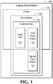
- Figure 1 is a block diagram of an example imaging device module 102.
- a slot interface 106 is fixedly coupled to a frame 142.
- the slot interface 106 comprises a guide member 116 that forms part of a channel.
- the guide member 116 includes a guide wall to guide a bracket in the channel as discussed further herein, a first panel portion substantially parallel to and in contact with the frame 142, and a second panel portion defining an aperture and not directly in contact with the frame 142.
- Figure 2 is a perspective view of an example system 100 of assembled example imaging device modules 102 and 104.
- Figure 2 depicts the components of a slot and bracket attachment as hidden underneath the cosmetic covers 112 and 114.
- the components of the slot and bracket attachment approach include a slot interface 106, a bracket 108, and a fastener 110 (e.g., multiple fasteners are shown in Figure 2 ).
- the covers 112 and 114 are shown on device modules 102 and 104, respectively, with the components of the slot and bracket attachment approach shown in dotted lines underneath the covers 112 and 114. In this manner, the form of the attachment is not visible to the end user because the cosmetic upper cover 112 and the cosmetic lower cover 114 conceal the attachment components connecting the structural frames of the modules 102 and 104.
- the cover 112 may be attached to a frame 142 to conceal a portion of the slot interface 106 (e.g. a portion of a guide member of the slot interface 106) and expose a portion of the slot interface 106 (e.g., an entry at an end of the slot interface 106 as discussed with reference to Figure 3 ), and the cover 114 may conceal the rest of the slot interface 106 not concealed by the cover 112.
- the covers 112 and 114 may be removable or otherwise movable away from the attachment site, such as an installation door on a hinge, to allow for access to the attachment site on the frame.
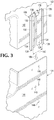
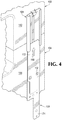
- Figures 3-5 are perspective views of example assembly states of an example system 100.
- Figure 3 is an example initial alignment state in which a first frame 142 of first device module 102 is being aligned with a second frame 144 of a second device module 104.
- a frame is a physical support structure of a device module and may be able to bear moments (e.g., forces) on the device module.
- the slot interface 106 is fixedly coupled to the first frame 142.
- the slot interface 106 may be connected to the frame 142 in any appropriate manner (such as fasteners or a rivet-less joining system) that generates a fixed coupling between the slot interface 106 and the frame 142.
- the connection may be rigid so that any moment carries as directly as possible through the slot interface 106.
- a portion of a guide member 116 may be securely fastened to the frame 142 based on mating contours, such as contours formed by a rivet-less joining system.
- the directness of the connection of the slot interface 106 to the frame 142 may, for example, improve the likelihood that a moment is transferred to the base module via the slot and bracket connection.
- the slot interface 106 generally includes a guide member that forms part of a channel.
- the slot interface 106 includes two guide members 116 and 118.
- the guide members generally include a guide wall, a portion in contact with the frame, and a portion not in contact with the frame.
- the guide member 116 includes a guide wall 120, a first panel portion 122 in contact with the frame 142, and a second panel portion 124 extending past the frame 142 and defining an aperture 126.
- the first panel portion 122 and the second panel portion 124 may be substantially parallel to the frame 142 and may be portions of the same panel.
- the guide member 116 of Figure 3 includes a fifth panel portion 128 that is opposite the first panel portion.
- the guide member 118 includes a guide wall 130, a third panel portion 132, a fourth panel portion 134, and a sixth panel portion 138 that are similar to (and correspond with) the components of the guide member 116.
- the guide members 116 and 118 define a channel.
- the fifth (front) panel portion 128 and the back panel (including portions 122 and 124 in Figure 3 ) define boundaries to a channel while the distance 140 between the guide walls 120 and 130 further define boundaries to the channel.
- the panel portions 122, 124, 132, and 134 define a frame-facing side of the channel
- the guide walls 130 and 120 define side walls substantially perpendicular to the frame surface
- the panels 128 and 138 define a side of the channel facing away from the frame 142
- corresponding ends of those components form an entry of the channel at an end of the slot interface 106 which is located vertically below the first frame as shown in Figure 3 .
- a bracket may be placed in the slot interface through an entry at the portion of slot interface 106 that extends beyond the frame 142 as depicted by Figure 4 .
- the device module 102 is aligned and placed adjacent to the device module 104 in the direction of arrow 166 so that the frames 142 and 144 are aligned.
- the aperture 126 of Figure 3 may align with an aperture of the frame 144.
- Other alignment features, such as features 148 of Figure 3 may designate locations to match the attachment components so that the bracket and slot interface properly align with the frames to transfer a moment. Alignment of the slot and bracket attachment components is discussed further with respect to Figure 6 .
- Figure 4 depicts the imaging system 100 with the components of a slot and bracket attachment approach in an example bracket installation state.
- the frames 142 and 144 of the modules 102 and 104 respectively are abutted and aligned to be flush on a surface.
- a bracket 108 is aligned with the slot interface 106 and may be pushed into the channel of the slot interface 106 in the direction of arrow 168.
- the bracket 108 may be oriented at an angle to the surface of the frame 144 during insertion into the slot interface 106, for example, to allow for the bracket 108 to pass by protruding alignment features.
- a first portion of the bracket 108 may be flat (such as the blade 172), tubular, or otherwise compatible with the slot interface (e.g., structured to snuggly fit in the channel of the slot interface) and a second portion of the bracket 108 may define an aperture 150 to assist fastening the bracket 108 to the slot interface 106 as shown in Figure 5 .
- Figure 5 depicts the imaging system 100 with the components of a slot and bracket attachment approach in a fastened state.
- the bracket 108 may slide into the slot interface 106 until an end cap 152 is reached at an end of the slot interface 106, where the end cap 152 may include a tab 154 to assist alignment of a projecting portion at an end of the slot interface 106.
- the end cap 152 may be a wall extending perpendicular from the frame-facing surface of the slot interface 106 to limit a distance of the bracket 108 along the channel of the slot interface 106 and the tab 154 may define a first surface that is tapered to assist contact of a second surface of the first portion of the bracket 108.
- the end cap 152 and tab 154 may be part of the slot interface and/or the frame.
- the bracket 108 may be aligned to an appropriate location in the slot interface 106 and/or an appropriate location on the frame 144.
- the bracket 108 may include alignment features 158 to assist orientation of the bracket 108.
- the bracket 108 may include a contour surface, such as contour 156 to allow the bracket to properly contact a surface of the frame 144 as well as a surface of the slot interface 106 so that the bracket 108 may be flush with both the slot interface 106 and the frame 144 at the same time (e.g., during a fastened state).
- the bracket 108 is fastened by to the slot interface 106 and/or the base device module frame 144.
- the fastener 110 connects the bracket 108 to both the slot interface 106 and the frame 144 of device module 104. In this manner, the modules 142 and 144 are connected via the slot and bracket combination.
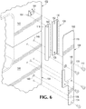
- Figure 6 is an exploded view of example components of an example system of example imaging device modules 102 and 104.
- the example system 100 of Figure 6 generally includes an upper device module 102, a lower device module 104, a bracket 108, and a fastener 110.
- Other example systems may include any appropriate number of the components in accordance with the desired model and the desired security of the attachment between modules.
- the system 100 of Figure 5 includes five fasteners 110 to attach the slot and bracket attachment components to the frame 144.
- the slot interface 106 is composed of a plurality of guide members (e.g., 116 and 118 of Figure 5 ) fixedly coupled to the frame 142.
- the slot interface may be composed of a single guide member with panels and guide walls integrated into the single guide member to define a channel to receive the bracket.
- the slot interface 106 may include an aperture 126 on a portion of the slot interface that extends passed the frame 142.
- the slot interface 106 includes multiple apertures 126 that extend past the upper frame 142 that correspond with apertures 146 in the lower frame 144.
- the lower frame 144 may include apertures 146 at different portions of the lower frame 144 to allow for the bracket 108 to be fastened at those locations of the lower frame 144.
- the bracket 108 includes a first portion at a first end of the bracket (e.g., the blade 172) and a second portion that defines an aperture 150.
- the first portion slidably fits in the channel defined by the slot interface 106.
- the aperture 150 defined by the second portion corresponds to an aperture 146 of the lower frame 144 and the aperture 126 of the slot interface 106.
- a fastener 110 couples the bracket 108, the slot interface 106, and the lower frame 144 at the apertures 126, 146, and 150 as depicted by line 170.
- the first frame 142 and second frame 144 may overlap and the fastener 110 may secure the bracket and the slot interface to both the first frame and the second frame along the same line.
- Alignment features may be provided in the components of the slot and bracket attachment approach that correspond to alignment features on the frames to assist in alignment of the components and device modules during assembly.
- an alignment feature includes any structural characteristic that identifies a location.
- Example alignment features include protrusions, projections, indents, apertures, or other structural profiles that may have corresponding contours with another alignment feature.
- an alignment feature may have a matching alignment feature to indicate when a component of the slot and bracket attachment is in a proper orientation and/or location.
- the upper device module 102 of Figure 6 includes an upper frame 142 with a plurality of alignment features 164 to align with a corresponding plurality of alignment features 162 of the slot interface 106.
- the upper frame 142 may include a first and second alignment feature 164 on the surface of the frame 142 where the guide members 116 and 118 include portions that define alignment features 162 corresponding to the first and second alignment features 164 on the upper frame 142.
- the lower device module 104 of Figure 5 includes lower frame 144 which may have a plurality of alignment features 148 corresponding to a plurality of alignment features 158 of the bracket 108.
- a first and second alignment features 158 may be offset to provide proper orientation of the bracket 108 to allow for the apertures 126, 146, and 150 to line up (as indicated by line 170 of Figure 6 ) and allow fastener 110 to secure the components together.
- the bracket 108 may include a blade (e.g., bracket portion 172) with tapered corners 160 at the end of the blade to assist insertion of the blade into the channel of the slot interface 106.
- the bracket 108 may include a contour where the blade portion 172 and the handle portion 174 are offset by a width of a frame-facing panel of the slot interface 106.
- the bracket 108 may be fastened to the slot interface 106 at about the midpoint of the bracket 108 and may also be fastened to the lower frame 144 at other locations to ensure secure fastening of the bracket 108 to the lower frame 144.
- the locations of fasteners 1 10 to secure the bracket 108 may be arranged based on the expected moment and/or desired transfer of moment by the slot and bracket attachment.
- FIG. 6 No specific indication of attachment of the slot interface 106 to the upper frame 142 is shown in Figure 6 . Any number of fastening techniques may be used.
- the guide members 116 and 118 may be securely fastened to the upper frame 142 by screws or a rivet-less technique.
- the degree of fastening of the slot interface 106 and the bracket 108 to the frames 142 and 144 may affect, for example, factors such as complexity of assembly and likelihood of a transfer of a possible moment.
- the bracket 108 is fastened to the lower frame 144 and is not fastened directly to the upper frame 142.
- the first portion of the bracket e.g. the blade 172
- the cover of the device module 102 may be left on during installation of the bracket 108 and otherwise during completion of the assembly of the device modules together to complete the system 100.
- assembly time may be reduced, for example, as well as allowing an orientation of the modules to allow for moment to be compensated for, even though the lower device module 104 and the upper device module 102 are not directly fastened, but are fastened indirectly via a bracket and slot interface connection.
- the components discussed herein may be made of sheet metal, plastic, or other structurally appropriate material.
- functionalities described herein in relation to any of Figures 1-6 may be provided in combination with functionalities described herein in relation to any of Figures 7-9 .
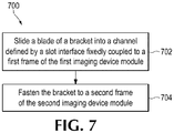
- Figures 7-9 are flow diagrams depicting example methods 700, 800, and 900 of connecting a first imaging device module to a second imaging device module.
- example method 700 of connecting a first imaging device module to a second imaging device module may generally comprise sliding a bracket into a slot interface fixedly coupled to the first imaging device module and fastening the bracket to the second imaging device module.
- a blade of a bracket is slid into a channel defined by a slot interface that is fixedly coupled to the frame of the first imaging device module.
- the blade of the bracket may be slid into the channel while a cosmetic cover is installed on the first imaging device module. In that example, assembly time may be saved by not having to take off the cover of the first imaging device module.
- the bracket is fastened to the frame of the second imaging device module. Though the bracket may not be directly fastened to the first frame, the bracket is able to transfer moment from the first frame via the slot interface and to the second frame via the direct fastening to the second frame.
- the cover of the second imaging device module may be removed (e.g., an installation door on the cosmetic cover of the device module is opened) to slide in and fasten the bracket and then reapplied (e.g., the installation door is closed) after the assembly is completed. In this manner, only the cover of the second imaging device module is manipulated and not the cover of the first imaging device module to perform the assembly of the first and second imaging device modules.
- Figure 8 includes blocks similar to blocks of Figure 7 and provides additional blocks and details.
- Figure 8 depicts additional blocks and details generally regarding aligning the bracket and fastening the bracket to the slot interface.
- Blocks 802 and 808 of method 800 are similar to blocks 702 and 704 of Figure 7 and, for brevity, their respective descriptions are not repeated.
- the bracket is aligned using a first plurality of alignment features on the bracket corresponding to a second plurality of alignment features on the frame of the second imaging device module.
- the bracket is fastened to the slot interface.
- the fastening of blocks 806 and 808 may be performed using the same fastener, such as depicted with regards to Figure 5 , so that the second frame, the slot interface, and the bracket are secured together using a fastener.
- Figure 9 is an example method 900 of connecting a first imaging device module to a second imaging device module that generally includes aligning the slot interface on the first imaging device module and securing the slot interface to the first imaging device module.
- the slot interface is aligned on a frame of the first imaging device module.
- the slot interface may be aligned using alignment features.
- the slot interface may be aligned so that a portion of the slot interface extends beyond the first frame (e.g., and extends onto a second frame with reference to the second frame of the second imaging device module when the modules are aligned and placed adjacent to the first imaging device module).
- the slot interface is securely joined to the frame of the first imaging device module.
- the slot interface may be securely joined to the frame of the first imaging device module using a rivet-less technique where force is applied to the surfaces of the slot interface and the frame of the first imaging device module so that they are modified to having mating contours that are secured together due to the shape of the contours.
- the methods 700 or 800 may follow the method 900 to complete the assembly operations of an imaging device, such as a multifunction printer.
Landscapes
- Studio Devices (AREA)
- Casings For Electric Apparatus (AREA)
Claims (15)
- Module de dispositif d'imagerie (102) comprenant :un cadre (142) ;une interface de fente (106) accouplée de manière ferme au cadre (142), l'interface de fente (106) comprenant :un premier élément de guidage (116) destiné à faire partie d'un canal, le premier élément de guidage (116) comprenant :une première paroi de guidage (120) ;une première partie de panneau (122) sensiblement parallèle au cadre (142) et en contact avec celui-ci ; etune deuxième partie de panneau (124) définissant une première ouverture (126), la deuxième partie de panneau (124) n'étant pas en contact avec le cadre (142).
- Module de dispositif d'imagerie selon la revendication 1, l'interface de fente (106) comprenant un second élément de guidage (118) faisant partie du canal et comprenant :une seconde paroi de guidage (130) ;une troisième partie de panneau (132) sensiblement parallèle au cadre (142) et en contact avec celui-ci ; etune quatrième partie de panneau (134) accouplée à la troisième partie de panneau (132), la quatrième partie de panneau (134) n'étant pas en contact avec le cadre (142) et définissant une deuxième ouverture (126).
- Module de dispositif d'imagerie selon la revendication 2 :le premier élément de guidage (116) comprenant en outre une cinquième partie de panneau (128) opposée à la première partie de panneau (122) ;le second élément de guidage (118) comprenant en outre une sixième partie de panneau (138) opposée à la troisième partie de panneau (132) ;la première partie de panneau (122), la deuxième partie de panneau (124), la troisième partie de panneau (132) et la quatrième partie de panneau (134) définissant un côté faisant face au cadre du canal défini par le premier élément de guidage (116) et le second élément de guidage (118) ; etle premier élément de guidage (116) et le second élément de guidage (118) formant une entrée du canal au niveau d'une première extrémité de l'interface de fente (106).
- Module de dispositif d'imagerie selon la revendication 3, comprenant :une butée d'extrémité (152) au niveau d'une seconde extrémité de l'interface de fente (106) ; etun élément de recouvrement (112) attaché au cadre (142), l'élément de recouvrement (112) dissimulant la première partie de panneau (122) du premier élément de guidage (116) et la troisième partie de panneau (132) du second élément de guidage (118) et exposant l'entrée au niveau de la première extrémité de l'interface de fente (106).
- Module de dispositif d'imagerie selon la revendication 3 ou 4 :
la première partie de panneau (122) et la troisième partie de panneau (132) étant fixées de manière sûre au cadre (142) sur la base de profils homologues. - Module de dispositif d'imagerie selon la revendication 3, 4 ou 5 :le cadre (142) comprenant en outre une première caractéristique d'alignement (164) sur la surface du cadre (142) et une deuxième caractéristique d'alignement (164) sur la surface du cadre (142) ;la première partie de panneau (122) du premier élément de guidage (116) définissant une troisième caractéristique d'alignement (162) correspondant à la première caractéristique d'alignement (164) du cadre (142) ; etla troisième partie de panneau (132) du second élément de guidage (118) définissant une quatrième caractéristique d'alignement (162) correspondant à la deuxième caractéristique d'alignement (164) du cadre (142).
- Système comprenant :un premier module de dispositif d'imagerie selon la revendication 2 ;un second module de dispositif (104) comprenant :un second cadre (144) ayant une partie de cadre définissant une deuxième ouverture (146) correspondant à la première ouverture (126) ;un support (108) comprenant :une première partie au niveau d'une première extrémité du support, la première partie devant rentrer de manière coulissante dans le canal ; etune deuxième partie qui définit une troisième ouverture (150) correspondant à la deuxième ouverture (146) ; etune première fixation (110) accouplant le support (108), l'interface de fente (106) et le second cadre (144) au niveau de la première ouverture (126), de la deuxième ouverture (146) et de la troisième ouverture (150).
- Système selon la revendication 7 :le premier cadre (142) ayant une première pluralité de caractéristiques d'alignement (164) correspondant à une deuxième pluralité de caractéristiques d'alignement (162) sur l'interface de fente (106) ; etle second cadre (144) ayant une troisième pluralité de caractéristiques d'alignement (148) correspondant à une quatrième pluralité de caractéristiques d'alignement (158) du support (108).
- Système selon la revendication 7 ou 8 :le support (108) étant fixé au second cadre (144) au niveau d'une troisième partie au niveau d'une seconde extrémité (174) du support (108) à l'aide d'une seconde fixation (110) ; etl'interface de fente (106) étant attachée au premier cadre (142) à l'aide d'une technique sans rivet.
- Système selon la revendication 9 :la première partie du support (108) comprenant une lame (172), la lame (172) ayant des coins effilés (160) au niveau de la première extrémité du support (108) pour aider à l'insertion dans le canal ;la première partie du support (108) et la troisième partie du support (108) étant décalées d'une largeur d'une surface de l'interface de fente (106) ; etla troisième ouverture (150) du support (108) étant située à peu près au milieu du support (108).
- Système selon l'une quelconque des revendications 7 à 10, comprenant en outre :une butée d'extrémité (152) pour limiter la distance du support (108) le long du canal ; etune languette (154) définissant une première surface qui entre en contact avec une seconde surface de la première partie du support (108), la première surface étant effilée.
- Système selon la revendication 11 :la première partie du support (108) étant uniquement liée au premier cadre (142) par l'intermédiaire de l'interface de fente (106) par la pluralité d'éléments de guidage (116, 118), la butée d'extrémité (152) et la languette (154) ; etla seconde partie du support (108) chevauchant uniquement le second cadre (144).
- Procédé de liaison d'un premier module de dispositif d'imagerie (102) et d'un second module de dispositif d'imagerie (104) comprenant :le coulissement d'une lame (172) d'un support (108) dans un canal défini par une interface de fente (106) accouplée de manière ferme à un premier cadre (142) du premier module de dispositif d'imagerie (102) ; etla fixation du support (108) à un second cadre (144) du second module de dispositif d'imagerie (108).
- Procédé selon la revendication 13, comprenant en outre :l'alignement du support (108) à l'aide d'une première pluralité de caractéristiques d'alignement (158) sur le support (108) correspondant à une seconde pluralité de caractéristiques d'alignement (148) sur le second cadre (144) ; etla fixation du support (108) à l'interface de fente (106).
- Procédé selon la revendication 14, comprenant en outre :l'alignement de l'interface de fente (106) sur le premier cadre (142) du premier module de dispositif d'imagerie (102), l'interface de fente (106) comprenant une première partie qui s'étend au-delà du premier cadre (142) ;l'assemblage sécurisé de l'interface de fente (106) au premier cadre (142) à l'aide d'une technique sans rivet :le coulissement de la lame (172) du support (108) dans le canal se produisant tandis qu'un recouvrement (112) du premier module de dispositif d'imagerie (102) est installé ; etla fixation du support (108) au second cadre (144) et la fixation du support (108) à l'interface de fente (106) étant effectuées à l'aide de la même fixation (110).
Applications Claiming Priority (1)
| Application Number | Priority Date | Filing Date | Title |
|---|---|---|---|
| PCT/US2016/027731 WO2017180146A1 (fr) | 2016-04-15 | 2016-04-15 | Interface de fente couplée de façon fixe à un cadre |
Publications (3)
| Publication Number | Publication Date |
|---|---|
| EP3442809A1 EP3442809A1 (fr) | 2019-02-20 |
| EP3442809A4 EP3442809A4 (fr) | 2019-12-11 |
| EP3442809B1 true EP3442809B1 (fr) | 2021-09-15 |
Family
ID=60042872
Family Applications (1)
| Application Number | Title | Priority Date | Filing Date |
|---|---|---|---|
| EP16898831.9A Not-in-force EP3442809B1 (fr) | 2016-04-15 | 2016-04-15 | Interface de fente couplée de façon fixe à un cadre |
Country Status (4)
| Country | Link |
|---|---|
| US (1) | US20190009587A1 (fr) |
| EP (1) | EP3442809B1 (fr) |
| CN (1) | CN109070615B (fr) |
| WO (1) | WO2017180146A1 (fr) |
Family Cites Families (9)
| Publication number | Priority date | Publication date | Assignee | Title |
|---|---|---|---|---|
| US4363459A (en) * | 1980-12-05 | 1982-12-14 | Joanna Western Mills Company | Adjustable wall mounted bracket |
| JPH08123579A (ja) * | 1994-10-27 | 1996-05-17 | Seiko Epson Corp | 情報処理装置およびプリンター |
| SE505883C2 (sv) * | 1996-09-12 | 1997-10-20 | Perstorp Ab | Väggbeklädnad för bland annat våtrum |
| US6758450B2 (en) * | 1999-11-05 | 2004-07-06 | Alfred G. Niederman | Modular furniture including interchangeable upholstery |
| KR20080041516A (ko) * | 2006-11-07 | 2008-05-13 | 삼성전자주식회사 | 화상형성장치 |
| CN201665917U (zh) * | 2010-03-08 | 2010-12-08 | 浙江桔乡建设有限公司 | 预制构件紧固件 |
| JP5002688B2 (ja) * | 2010-07-12 | 2012-08-15 | 本田技研工業株式会社 | 筐体取付構造 |
| CN104669801A (zh) * | 2013-11-27 | 2015-06-03 | 威海新北洋数码科技股份有限公司 | 便于维护打印机的自助服务设备 |
| CN104006275B (zh) * | 2014-06-16 | 2016-03-09 | 深圳市华星光电技术有限公司 | 一种壁挂装置 |
-
2016
- 2016-04-15 US US16/064,206 patent/US20190009587A1/en not_active Abandoned
- 2016-04-15 EP EP16898831.9A patent/EP3442809B1/fr not_active Not-in-force
- 2016-04-15 WO PCT/US2016/027731 patent/WO2017180146A1/fr not_active Ceased
- 2016-04-15 CN CN201680084014.3A patent/CN109070615B/zh not_active Expired - Fee Related
Also Published As
| Publication number | Publication date |
|---|---|
| CN109070615B (zh) | 2021-02-12 |
| EP3442809A4 (fr) | 2019-12-11 |
| EP3442809A1 (fr) | 2019-02-20 |
| CN109070615A (zh) | 2018-12-21 |
| US20190009587A1 (en) | 2019-01-10 |
| WO2017180146A1 (fr) | 2017-10-19 |
Similar Documents
| Publication | Publication Date | Title |
|---|---|---|
| US10813478B2 (en) | System for retaining an image within a frame | |
| US8938182B2 (en) | Stand of image forming apparatus and image forming apparatus having the same | |
| CN103167813B (zh) | 家具抽拉部件 | |
| CA3147025A1 (fr) | Systeme de suspension de plafond ayant un support de couplage a pattes de retenue elastiques | |
| JP7677060B2 (ja) | 筐体構造及びこれを用いた処理装置 | |
| EP2998951B1 (fr) | Dispositif d'affichage d'image et de montage | |
| US20190009587A1 (en) | Slot interface fixedly coupled to frame | |
| EP2675628B1 (fr) | Reliure de supports | |
| US20180044973A1 (en) | Garage door re-facing system | |
| EP3204931B1 (fr) | Repère de bornes à monture souple | |
| US20160318463A1 (en) | License plate mounting system | |
| JP7608258B2 (ja) | 画像形成装置 | |
| US12239249B2 (en) | Graphics display apparatus | |
| US7240447B2 (en) | Mix and match framing system | |
| KR200485470Y1 (ko) | 가구용 코너 마감재 | |
| CN107517545B (zh) | 电控箱 | |
| CN209331706U (zh) | 一种组合式安装支架 | |
| CN103365141A (zh) | 图像形成装置 | |
| KR101792179B1 (ko) | 스크린 설치용 클립 | |
| CN110043168B (zh) | 一种方便安装和拆卸的回卷纱窗或三滑纱窗及窗框连接件 | |
| US8582284B2 (en) | Media display fixture for an electronic kiosk | |
| NL2014591A (en) | Tray Locking Device for Reproduction System. | |
| EP3549479B1 (fr) | Fixation de cadre à une valise | |
| CA2984314C (fr) | Assemblages de canal modulaire destines a des portes | |
| JP3065012U (ja) | クロ―ゼットドアの背面板の取付構造 |
Legal Events
| Date | Code | Title | Description |
|---|---|---|---|
| STAA | Information on the status of an ep patent application or granted ep patent |
Free format text: STATUS: THE INTERNATIONAL PUBLICATION HAS BEEN MADE |
|
| PUAI | Public reference made under article 153(3) epc to a published international application that has entered the european phase |
Free format text: ORIGINAL CODE: 0009012 |
|
| STAA | Information on the status of an ep patent application or granted ep patent |
Free format text: STATUS: REQUEST FOR EXAMINATION WAS MADE |
|
| 17P | Request for examination filed |
Effective date: 20180723 |
|
| AK | Designated contracting states |
Kind code of ref document: A1 Designated state(s): AL AT BE BG CH CY CZ DE DK EE ES FI FR GB GR HR HU IE IS IT LI LT LU LV MC MK MT NL NO PL PT RO RS SE SI SK SM TR |
|
| AX | Request for extension of the european patent |
Extension state: BA ME |
|
| RAP1 | Party data changed (applicant data changed or rights of an application transferred) |
Owner name: HEWLETT-PACKARD DEVELOPMENT COMPANY, L.P. |
|
| DAV | Request for validation of the european patent (deleted) | ||
| DAX | Request for extension of the european patent (deleted) | ||
| A4 | Supplementary search report drawn up and despatched |
Effective date: 20191113 |
|
| RIC1 | Information provided on ipc code assigned before grant |
Ipc: B41J 29/54 20060101ALI20191107BHEP Ipc: B41J 29/02 20060101AFI20191107BHEP Ipc: B41J 29/13 20060101ALI20191107BHEP |
|
| STAA | Information on the status of an ep patent application or granted ep patent |
Free format text: STATUS: EXAMINATION IS IN PROGRESS |
|
| 17Q | First examination report despatched |
Effective date: 20201118 |
|
| GRAP | Despatch of communication of intention to grant a patent |
Free format text: ORIGINAL CODE: EPIDOSNIGR1 |
|
| STAA | Information on the status of an ep patent application or granted ep patent |
Free format text: STATUS: GRANT OF PATENT IS INTENDED |
|
| INTG | Intention to grant announced |
Effective date: 20210514 |
|
| GRAS | Grant fee paid |
Free format text: ORIGINAL CODE: EPIDOSNIGR3 |
|
| GRAA | (expected) grant |
Free format text: ORIGINAL CODE: 0009210 |
|
| STAA | Information on the status of an ep patent application or granted ep patent |
Free format text: STATUS: THE PATENT HAS BEEN GRANTED |
|
| AK | Designated contracting states |
Kind code of ref document: B1 Designated state(s): AL AT BE BG CH CY CZ DE DK EE ES FI FR GB GR HR HU IE IS IT LI LT LU LV MC MK MT NL NO PL PT RO RS SE SI SK SM TR |
|
| REG | Reference to a national code |
Ref country code: CH Ref legal event code: EP |
|
| REG | Reference to a national code |
Ref country code: DE Ref legal event code: R096 Ref document number: 602016063879 Country of ref document: DE |
|
| REG | Reference to a national code |
Ref country code: IE Ref legal event code: FG4D |
|
| REG | Reference to a national code |
Ref country code: AT Ref legal event code: REF Ref document number: 1430233 Country of ref document: AT Kind code of ref document: T Effective date: 20211015 |
|
| REG | Reference to a national code |
Ref country code: LT Ref legal event code: MG9D |
|
| REG | Reference to a national code |
Ref country code: NL Ref legal event code: MP Effective date: 20210915 |
|
| PG25 | Lapsed in a contracting state [announced via postgrant information from national office to epo] |
Ref country code: RS Free format text: LAPSE BECAUSE OF FAILURE TO SUBMIT A TRANSLATION OF THE DESCRIPTION OR TO PAY THE FEE WITHIN THE PRESCRIBED TIME-LIMIT Effective date: 20210915 Ref country code: SE Free format text: LAPSE BECAUSE OF FAILURE TO SUBMIT A TRANSLATION OF THE DESCRIPTION OR TO PAY THE FEE WITHIN THE PRESCRIBED TIME-LIMIT Effective date: 20210915 Ref country code: BG Free format text: LAPSE BECAUSE OF FAILURE TO SUBMIT A TRANSLATION OF THE DESCRIPTION OR TO PAY THE FEE WITHIN THE PRESCRIBED TIME-LIMIT Effective date: 20211215 Ref country code: LT Free format text: LAPSE BECAUSE OF FAILURE TO SUBMIT A TRANSLATION OF THE DESCRIPTION OR TO PAY THE FEE WITHIN THE PRESCRIBED TIME-LIMIT Effective date: 20210915 Ref country code: NO Free format text: LAPSE BECAUSE OF FAILURE TO SUBMIT A TRANSLATION OF THE DESCRIPTION OR TO PAY THE FEE WITHIN THE PRESCRIBED TIME-LIMIT Effective date: 20211215 Ref country code: HR Free format text: LAPSE BECAUSE OF FAILURE TO SUBMIT A TRANSLATION OF THE DESCRIPTION OR TO PAY THE FEE WITHIN THE PRESCRIBED TIME-LIMIT Effective date: 20210915 Ref country code: FI Free format text: LAPSE BECAUSE OF FAILURE TO SUBMIT A TRANSLATION OF THE DESCRIPTION OR TO PAY THE FEE WITHIN THE PRESCRIBED TIME-LIMIT Effective date: 20210915 |
|
| REG | Reference to a national code |
Ref country code: AT Ref legal event code: MK05 Ref document number: 1430233 Country of ref document: AT Kind code of ref document: T Effective date: 20210915 |
|
| PG25 | Lapsed in a contracting state [announced via postgrant information from national office to epo] |
Ref country code: LV Free format text: LAPSE BECAUSE OF FAILURE TO SUBMIT A TRANSLATION OF THE DESCRIPTION OR TO PAY THE FEE WITHIN THE PRESCRIBED TIME-LIMIT Effective date: 20210915 Ref country code: GR Free format text: LAPSE BECAUSE OF FAILURE TO SUBMIT A TRANSLATION OF THE DESCRIPTION OR TO PAY THE FEE WITHIN THE PRESCRIBED TIME-LIMIT Effective date: 20211216 |
|
| PG25 | Lapsed in a contracting state [announced via postgrant information from national office to epo] |
Ref country code: AT Free format text: LAPSE BECAUSE OF FAILURE TO SUBMIT A TRANSLATION OF THE DESCRIPTION OR TO PAY THE FEE WITHIN THE PRESCRIBED TIME-LIMIT Effective date: 20210915 |
|
| PGFP | Annual fee paid to national office [announced via postgrant information from national office to epo] |
Ref country code: GB Payment date: 20220323 Year of fee payment: 7 |
|
| PG25 | Lapsed in a contracting state [announced via postgrant information from national office to epo] |
Ref country code: IS Free format text: LAPSE BECAUSE OF FAILURE TO SUBMIT A TRANSLATION OF THE DESCRIPTION OR TO PAY THE FEE WITHIN THE PRESCRIBED TIME-LIMIT Effective date: 20220115 Ref country code: SM Free format text: LAPSE BECAUSE OF FAILURE TO SUBMIT A TRANSLATION OF THE DESCRIPTION OR TO PAY THE FEE WITHIN THE PRESCRIBED TIME-LIMIT Effective date: 20210915 Ref country code: SK Free format text: LAPSE BECAUSE OF FAILURE TO SUBMIT A TRANSLATION OF THE DESCRIPTION OR TO PAY THE FEE WITHIN THE PRESCRIBED TIME-LIMIT Effective date: 20210915 Ref country code: RO Free format text: LAPSE BECAUSE OF FAILURE TO SUBMIT A TRANSLATION OF THE DESCRIPTION OR TO PAY THE FEE WITHIN THE PRESCRIBED TIME-LIMIT Effective date: 20210915 Ref country code: PT Free format text: LAPSE BECAUSE OF FAILURE TO SUBMIT A TRANSLATION OF THE DESCRIPTION OR TO PAY THE FEE WITHIN THE PRESCRIBED TIME-LIMIT Effective date: 20220117 Ref country code: PL Free format text: LAPSE BECAUSE OF FAILURE TO SUBMIT A TRANSLATION OF THE DESCRIPTION OR TO PAY THE FEE WITHIN THE PRESCRIBED TIME-LIMIT Effective date: 20210915 Ref country code: NL Free format text: LAPSE BECAUSE OF FAILURE TO SUBMIT A TRANSLATION OF THE DESCRIPTION OR TO PAY THE FEE WITHIN THE PRESCRIBED TIME-LIMIT Effective date: 20210915 Ref country code: ES Free format text: LAPSE BECAUSE OF FAILURE TO SUBMIT A TRANSLATION OF THE DESCRIPTION OR TO PAY THE FEE WITHIN THE PRESCRIBED TIME-LIMIT Effective date: 20210915 Ref country code: EE Free format text: LAPSE BECAUSE OF FAILURE TO SUBMIT A TRANSLATION OF THE DESCRIPTION OR TO PAY THE FEE WITHIN THE PRESCRIBED TIME-LIMIT Effective date: 20210915 Ref country code: CZ Free format text: LAPSE BECAUSE OF FAILURE TO SUBMIT A TRANSLATION OF THE DESCRIPTION OR TO PAY THE FEE WITHIN THE PRESCRIBED TIME-LIMIT Effective date: 20210915 Ref country code: AL Free format text: LAPSE BECAUSE OF FAILURE TO SUBMIT A TRANSLATION OF THE DESCRIPTION OR TO PAY THE FEE WITHIN THE PRESCRIBED TIME-LIMIT Effective date: 20210915 |
|
| PGFP | Annual fee paid to national office [announced via postgrant information from national office to epo] |
Ref country code: FR Payment date: 20220322 Year of fee payment: 7 |
|
| REG | Reference to a national code |
Ref country code: DE Ref legal event code: R097 Ref document number: 602016063879 Country of ref document: DE |
|
| PLBE | No opposition filed within time limit |
Free format text: ORIGINAL CODE: 0009261 |
|
| STAA | Information on the status of an ep patent application or granted ep patent |
Free format text: STATUS: NO OPPOSITION FILED WITHIN TIME LIMIT |
|
| PG25 | Lapsed in a contracting state [announced via postgrant information from national office to epo] |
Ref country code: DK Free format text: LAPSE BECAUSE OF FAILURE TO SUBMIT A TRANSLATION OF THE DESCRIPTION OR TO PAY THE FEE WITHIN THE PRESCRIBED TIME-LIMIT Effective date: 20210915 |
|
| PGFP | Annual fee paid to national office [announced via postgrant information from national office to epo] |
Ref country code: DE Payment date: 20220322 Year of fee payment: 7 |
|
| 26N | No opposition filed |
Effective date: 20220616 |
|
| PG25 | Lapsed in a contracting state [announced via postgrant information from national office to epo] |
Ref country code: SI Free format text: LAPSE BECAUSE OF FAILURE TO SUBMIT A TRANSLATION OF THE DESCRIPTION OR TO PAY THE FEE WITHIN THE PRESCRIBED TIME-LIMIT Effective date: 20210915 |
|
| REG | Reference to a national code |
Ref country code: CH Ref legal event code: PL |
|
| REG | Reference to a national code |
Ref country code: BE Ref legal event code: MM Effective date: 20220430 |
|
| PG25 | Lapsed in a contracting state [announced via postgrant information from national office to epo] |
Ref country code: MC Free format text: LAPSE BECAUSE OF FAILURE TO SUBMIT A TRANSLATION OF THE DESCRIPTION OR TO PAY THE FEE WITHIN THE PRESCRIBED TIME-LIMIT Effective date: 20210915 Ref country code: LU Free format text: LAPSE BECAUSE OF NON-PAYMENT OF DUE FEES Effective date: 20220415 Ref country code: LI Free format text: LAPSE BECAUSE OF NON-PAYMENT OF DUE FEES Effective date: 20220430 Ref country code: IT Free format text: LAPSE BECAUSE OF FAILURE TO SUBMIT A TRANSLATION OF THE DESCRIPTION OR TO PAY THE FEE WITHIN THE PRESCRIBED TIME-LIMIT Effective date: 20210915 Ref country code: CH Free format text: LAPSE BECAUSE OF NON-PAYMENT OF DUE FEES Effective date: 20220430 |
|
| PG25 | Lapsed in a contracting state [announced via postgrant information from national office to epo] |
Ref country code: BE Free format text: LAPSE BECAUSE OF NON-PAYMENT OF DUE FEES Effective date: 20220430 |
|
| PG25 | Lapsed in a contracting state [announced via postgrant information from national office to epo] |
Ref country code: IE Free format text: LAPSE BECAUSE OF NON-PAYMENT OF DUE FEES Effective date: 20220415 |
|
| REG | Reference to a national code |
Ref country code: DE Ref legal event code: R119 Ref document number: 602016063879 Country of ref document: DE |
|
| GBPC | Gb: european patent ceased through non-payment of renewal fee |
Effective date: 20230415 |
|
| PG25 | Lapsed in a contracting state [announced via postgrant information from national office to epo] |
Ref country code: GB Free format text: LAPSE BECAUSE OF NON-PAYMENT OF DUE FEES Effective date: 20230415 |
|
| PG25 | Lapsed in a contracting state [announced via postgrant information from national office to epo] |
Ref country code: GB Free format text: LAPSE BECAUSE OF NON-PAYMENT OF DUE FEES Effective date: 20230415 Ref country code: FR Free format text: LAPSE BECAUSE OF NON-PAYMENT OF DUE FEES Effective date: 20230430 Ref country code: DE Free format text: LAPSE BECAUSE OF NON-PAYMENT OF DUE FEES Effective date: 20231103 |
|
| PG25 | Lapsed in a contracting state [announced via postgrant information from national office to epo] |
Ref country code: HU Free format text: LAPSE BECAUSE OF FAILURE TO SUBMIT A TRANSLATION OF THE DESCRIPTION OR TO PAY THE FEE WITHIN THE PRESCRIBED TIME-LIMIT; INVALID AB INITIO Effective date: 20160415 |
|
| PG25 | Lapsed in a contracting state [announced via postgrant information from national office to epo] |
Ref country code: MK Free format text: LAPSE BECAUSE OF FAILURE TO SUBMIT A TRANSLATION OF THE DESCRIPTION OR TO PAY THE FEE WITHIN THE PRESCRIBED TIME-LIMIT Effective date: 20210915 Ref country code: CY Free format text: LAPSE BECAUSE OF FAILURE TO SUBMIT A TRANSLATION OF THE DESCRIPTION OR TO PAY THE FEE WITHIN THE PRESCRIBED TIME-LIMIT Effective date: 20210915 |
|
| PG25 | Lapsed in a contracting state [announced via postgrant information from national office to epo] |
Ref country code: TR Free format text: LAPSE BECAUSE OF FAILURE TO SUBMIT A TRANSLATION OF THE DESCRIPTION OR TO PAY THE FEE WITHIN THE PRESCRIBED TIME-LIMIT Effective date: 20210915 |
|
| PG25 | Lapsed in a contracting state [announced via postgrant information from national office to epo] |
Ref country code: MT Free format text: LAPSE BECAUSE OF FAILURE TO SUBMIT A TRANSLATION OF THE DESCRIPTION OR TO PAY THE FEE WITHIN THE PRESCRIBED TIME-LIMIT Effective date: 20210915 |