EP3443157B1 - Bodenmodul für ein haushaltsgerät zum trocknen von wäsche sowie haushaltsgerät - Google Patents
Bodenmodul für ein haushaltsgerät zum trocknen von wäsche sowie haushaltsgerät Download PDFInfo
- Publication number
- EP3443157B1 EP3443157B1 EP17707521.5A EP17707521A EP3443157B1 EP 3443157 B1 EP3443157 B1 EP 3443157B1 EP 17707521 A EP17707521 A EP 17707521A EP 3443157 B1 EP3443157 B1 EP 3443157B1
- Authority
- EP
- European Patent Office
- Prior art keywords
- component
- adapter
- heat
- pipe
- base module
- Prior art date
- Legal status (The legal status is an assumption and is not a legal conclusion. Google has not performed a legal analysis and makes no representation as to the accuracy of the status listed.)
- Active
Links
Images


Classifications
-
- D—TEXTILES; PAPER
- D06—TREATMENT OF TEXTILES OR THE LIKE; LAUNDERING; FLEXIBLE MATERIALS NOT OTHERWISE PROVIDED FOR
- D06F—LAUNDERING, DRYING, IRONING, PRESSING OR FOLDING TEXTILE ARTICLES
- D06F58/00—Domestic laundry dryers
- D06F58/20—General details of domestic laundry dryers
-
- D—TEXTILES; PAPER
- D06—TREATMENT OF TEXTILES OR THE LIKE; LAUNDERING; FLEXIBLE MATERIALS NOT OTHERWISE PROVIDED FOR
- D06F—LAUNDERING, DRYING, IRONING, PRESSING OR FOLDING TEXTILE ARTICLES
- D06F58/00—Domestic laundry dryers
- D06F58/20—General details of domestic laundry dryers
- D06F58/206—Heat pump arrangements
Definitions
- the invention relates to a floor module for holding a heat pump of a household appliance for drying laundry, comprising at least one heat exchanger receiving area for at least partially receiving at least one heat exchanger of the heat pump, at least one component receiving area for at least partially receiving a compressor and / or a throttle of the heat pump and at least one of the Heat exchanger receiving area at least partially separating from the component receiving area, on which at least one pipe lead-through for leading a pipeline of a refrigerant circuit of the heat pump is arranged, the partition being formed at least partially by at least one adapter component having the pipe lead-through, the adapter component having a pipe lead-through Feedthrough section made of flexible plastic in the form of a foam or an elastomer or one with a foil having llten assembly foam, and wherein the adapter member is formed of two superimposed adapter parts, wherein the tube guide is formed of two adapter parts.
- the invention relates to a household appliance for drying laundry, comprising at least one heat pump.
- Heat pumps are installed in household appliances for drying laundry to improve energy efficiency.
- differently designed heat pumps are used, which are held by a floor module of the household appliance in their respective intended use positions.
- the heat exchangers (evaporator, condenser) of heat pumps with regard to their size and / or the arrangement of the inlet connections and the outlet connections of the heat exchangers, on the pipes of the refrigerant circuit the heat pump can be connected, be designed differently.
- the heat exchangers can be arranged in different positions.
- a floor module usually comprises a module housing with a heat exchanger receiving area for receiving the heat exchangers of the heat pump.
- the heat exchanger receiving area is connected to a process air circuit of the household appliance and sealed from the environment.
- the heat exchanger receiving area is separated by a partition from a component receiving area of the base module, which is used to receive a compressor and / or a throttle of the heat pump.
- pipes of the refrigerant circuit are guided through the partition wall, on which pipe ducts are formed for this purpose.
- the dimensioning and positioning of the pipe bushings is adapted to the dimensioning and positioning of the pipe sections led through the partition.
- a floor module is known in which the partition is at least partially formed by at least one separately formed adapter component having at least one pipe bushing.
- the floor module can be adapted to the configuration of the heat pump with significantly less effort.
- This adaptation of the floor module to the respective design of the heat pump can be carried out shortly before the installation of a floor module or a household appliance equipped with it by using an adapter component which is adapted to the design of the heat pump.
- the floor module can thus be easily combined with existing designs of heat pumps as well as future designs of heat pumps.
- the floor module can be easily adapted to wider and / or higher heat exchangers or to the design of the refrigerant circuit required in each case by the choice of a suitable adapter component.
- transport, administration and storage of complete floor modules can be omitted. It is only necessary to manufacture, store and transport the much smaller adapter components in different versions.
- the use of such floor modules also makes it possible for a manufacturer of floor modules to react quickly to different market requirements.
- EP 2 881 514 A1 discloses a clothes dryer with a heat pump device, the heat exchanger of which has a pipe loop system guided by fins, the heat exchanger being arranged for cooling and / or heating a process air flow in a flow channel with shields arranged at the side.
- the shields consist of molded body elements which essentially fill the free installation space located to the side in the flow channel or the lateral cavity of the heat exchanger.
- EP 2 915 916 A1 discloses a clothes dryer with a heat pump device, the heat exchanger of which is arranged in a flow channel, the heat exchanger being connected to a compressor via refrigerant pipes which are laid through openings arranged in the wall of the flow channel.
- the flow channel is formed from partial shells, with the refrigerant tubes being arranged in the partial shells in the connection region of the shells in the partial openings provided for this purpose.
- Profiles in the form of a support and an arch are formed on the partial openings of the partial shells and extend transversely to the plane of the wall of the flow channel.
- An object of the invention is to reduce the effort associated with the production of household appliances for drying laundry.
- a floor module for holding a heat pump of a household appliance for drying laundry comprises at least one heat exchanger receiving area for at least partially receiving at least one heat exchanger of the heat pump, at least one component receiving area for at least partially receiving a compressor and / or a throttle of the heat pump and at least one at least partially the heat exchanger receiving area Partition separating from the component receiving area, on which at least one pipe bushing for guiding a pipe through a refrigerant circuit of the heat pump is arranged.
- the partition is at least partially formed by at least one separately formed adapter component having the pipe leadthrough.
- the adapter component comprises a bushing section comprising the pipe bushing made of a resilient plastic in the form of a foam or an elastomer or an assembly foam encased in a film.
- the adapter component is formed from two adapter parts lying one on top of the other, the pipe bushing being formed by both adapter parts.
- the adapter parts are provided with slots on the pipe bushing.
- the lead-through section of the adapter component surrounding the pipe lead-through is designed to be flexible or elastically deformable, as a result of which variations in the positioning and dimensioning of the line section of the pipeline guided through the pipe lead-through can be absorbed with one and the same adapter component, without structural changes having to be made to the adapter component , Due to the flexibility of the lead-through section, an inclination of the line section can also be compensated for with one and the same adapter component. In order to be able to accommodate these variations, it is not necessary, as is customary, to either produce and use entire module housings or adapter components specifically.
- the design of the partition wall is largely independent of the respective design of the heat pump to be installed.
- the term “resilience” means that the lead-through section of the adapter component deforms elastically due to physical contact with the at least one pipeline in order to be able to compensate for a positional tolerance between the adapter component and the pipeline.
- the lead-through section inevitably adapts optimally to the position and shape of the pipeline, which is particularly advantageous with regard to the required sealing of the heat exchanger receiving area from the surroundings.
- tolerance compensation cannot be realized with an adapter component that is not compliant or completely dimensionally stable. Instead, with such a conventional adapter component, there would be an undesired deformation of the pipeline if there were positional tolerances.
- the adapter component can also be formed entirely from the resilient plastic or through the lead-through section.
- the adapter component can be connectable to the rest of the partition via at least one non-destructively releasable connecting means.
- two or more pipe bushings can also be formed on the bushing section or the adapter component for bushing one pipe of the refrigerant circuit of the heat pump.
- the adapter parts each hold the pipe to be carried out between them.
- the partition can be partially or completely formed by the separately formed adapter component.
- the partition can also be formed, at least in part, by two or more adapter components which are combined with one another to form an adapter assembly.
- the heat exchanger receiving area can be designed to receive one or both heat exchangers of the heat pump.
- the component receiving area can extend along part of the length of the heat exchanger receiving area or over the entire length of the heat exchanger receiving area.
- the lead-through section or the entire adapter component can be formed by a resilient foam or a resilient molded foam component.
- the lead-through section or the entire adapter component can be designed as a one, two or more-part rubber molded component.
- a plastic composite is formed by the film and the mounting foam, which in the context of the invention is simply referred to as plastic.
- the slots on the pipe leadthroughs of the adapter parts facilitate the deformation of the adapter parts when the pipe is passed through and may make it unnecessary to preform the pipe leadthroughs - especially if a correspondingly flexible and deformable foam is used for the adapter parts. This may simplify the manufacture of the adapter parts and make the assembly of the pipes in the bushings between the adapter parts safer and easier.
- At least one flexible sealing element for sealing the heat exchanger receiving area from an environment is arranged on the adapter component.
- the flexible sealing element can be arranged all around on the adapter component.
- the sealing element can be made of an elastomer, for example.
- the sealing element can be produced separately or monolithically with a section of the adapter component.
- the base module is a module housing with a base-side receiving component on which the heat exchanger receiving area and the component receiving area are formed, and has a heat exchanger cover which closes the heat exchanger receiving area on the bottom side, a first frame element being arranged on a wall section of the partition wall connected to the receiving component and a second frame element being arranged on the heat exchanger cover, and the frame elements forming a frame for positively receiving the adapter component
- the entire adapter component can be made of the resilient plastic as a molded component.
- the adapter component comprises a dimensionally stable frame component that can be connected to the other partition and a pipe lead-through component encased in the frame component, the pipe lead-through component being made of the resilient plastic.
- the pipe bushing component forms the bushing section of the adapter component.
- the frame component can be used to fix the adapter component to the module housing.
- the frame component can be designed as a round or square frame.
- the adapter component or the pipe bushing component can in this case be flat and comparatively large, as a result of which a large area is available for carrying out the pipeline.
- the pipe bushing component can be made of a thermoplastic elastomer or a similar two-component material. Apart from the pipe bushings, the adapter component can be manufactured as the same part.
- the frame component is advantageously made of a thermoplastic.
- the pipe bushing component can then be arranged on the frame component thus produced from a hard plastic.
- an elastomeric material can be injected into it to form a flexible sealing element which is arranged between the frame component and the module housing in order to improve the sealing of the heat exchanger receiving area.
- the frame component is connected to the rest of the partition by at least one screw connection or at least one snap connection. This makes it easy to assemble and disassemble the adapter component.
- the pipe leadthrough is produced by a punching process.
- the punching can be done directly on the assembly line.
- the adapter component or the pipe lead-through component can then be pushed onto a pipe end of the pipeline. This pushing on can be carried out before the heat exchanger is installed on the module housing.
- the punching is designed in such a way that a circumferential encirclement of the line section guided through the pipe bushing is ensured.
- the line section penetrates the pre-punched pipe bushing like a membrane.
- the pipe lead-through component lies radially around the circumference of the line section.
- a household appliance according to the invention for drying laundry comprises at least one heat pump and at least one floor module according to the aforementioned configuration according to the invention.
- the advantages mentioned above with regard to the floor module are correspondingly associated with the household appliance.
- the household appliance can be designed, for example, as a clothes dryer or washer dryer.
- Fig. 1 shows a schematic and perspective view of an embodiment of a floor module 1 for holding a heat pump, not shown, of a household appliance 15 for drying laundry.
- the floor module 1 comprises a heat exchanger receiving area 2 for receiving heat exchangers (not shown) of the heat pump and a component receiving area 3 for at least partially receiving a compressor (not shown) and / or a throttle (not shown) of the heat pump.
- the base module 1 comprises a module housing 4 with a base-side receiving component 5, on which the heat exchanger receiving region 2 and the component receiving region 3 are formed, and a heat exchanger cover 6, which closes the heat exchanger receiving region 2 on the bottom side, the construction of which Fig. 2 becomes clearer.
- the floor module 1 further comprises a partition 7 separating the heat exchanger receiving area 2 from the component receiving area 3, on which are arranged four pipe bushings 8 for the passage of a pipe, not shown, of a refrigerant circuit of the heat pump.
- the pipe bushings 8 can be produced, for example, by a punching process.
- the partition 7 is partially formed by a separately formed adapter component 9 having the pipe bushings 8.
- the adapter component 9 consists entirely of a resilient plastic, that is to say it comprises a bushing section having the pipe bushings 8 made of a resilient plastic.
- the resilient plastic can be a foam, an elastomer or an assembly foam encased in a film.
- the adapter component 9 is designed as a two-part molded body, the two adapter parts 10 and 11 being separated along an essentially horizontal parting plane 12.
- a first frame element 13 is arranged on a wall section of the partition 7 connected to the receiving component 5 and a second frame element 14 is arranged on the heat exchanger cover 6, the frame elements 13 and 14 forming a frame for the form-fitting reception of the adapter component 9.
- the wall section of the partition 7 connected to the adapter component 9 is formed by a separate wall component 16 which is positively connected to the rest of the partition 17.
- the wall component 16 can be formed separately or can be injection molded onto the receiving component 5.
- Fig. 2 shows a schematic and perspective detailed view of the in Fig. 1 shown floor module 1. Only the heat exchanger cover 6, the adapter component 9 and the wall component 16 are shown.
- Fig. 3 shows a further schematic and perspective detailed representation of the in Fig. 1 Floor module 1 shown. Only the adapter component 9 and the wall component 16 are shown.
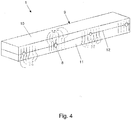
- Fig. 4 shows a further schematic and perspective detailed representation of the in Fig. 1 shown floor module 1. Only the cuboid adapter 9 is shown.
- the adapter component 9 is formed from two adapter parts 10 and 11 lying one on top of the other, the pipe bushings 8 being formed by both adapter parts 10 and 11 - here in each case half.
- Each adapter part 10 or 11 is provided with slots 38 on each pipe bushing 8. As a result, each adapter part 10 or 11 can better nestle against the pipe guided through the pipe bushing 8. If necessary, it can be refrained from preforming the pipe bushing 8 in addition to the slots, in particular if the adapter parts 10 and 11 consist of a correspondingly flexible and deformable foam.
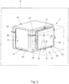
- Fig. 5 shows a schematic and perspective view of a further embodiment of a floor module 1 for holding a heat pump 18 of a household appliance 15 for drying laundry, this embodiment not being part of the claimed invention.
- the floor module 1 comprises a heat exchanger receiving area 19 for receiving heat exchangers 20 of the heat pump 18, of which in Fig. 5 only one heat exchanger 20 is shown, and a component receiving area 21 for at least partially receiving a compressor (not shown) and / or a throttle (not shown) of the heat pump 18.
- the base module 1 comprises a module housing 22 with a base-side receiving component 23 on which the heat exchanger receiving area 19 and the component receiving area 21 are formed, and a heat exchanger cover 24 which closes the heat exchanger receiving area 19 on the bottom side.
- the floor module 1 further comprises a partition wall 25 separating the heat exchanger receiving area 19 from the component receiving area 21, on which four pipe lead-throughs 26 for carrying out a respective pipe 27 of a refrigerant circuit Heat pump 18 are arranged.
- the pipe bushings 26 can be produced, for example, by a stamping process.
- the partition wall 25 is partially formed by a separately formed adapter component 28 having the pipe bushings 26.
- the adapter component 28 comprises a dimensionally stable frame component 29 made of a thermoplastic plastic and connected to the remaining partition 37 and a pipe lead-through component 30 encased in the frame component 29, the tube lead-through component 30 being made of a resilient plastic. Consequently, the adapter component 28 comprises a bushing section having the pipe bushings 26 made of a flexible plastic.
- the frame component 29 can be connected to the remaining partition 37 via at least one screw connection, not shown, or at least one snap connection, not shown, for which purpose four outward-facing fastening tabs 31 are arranged on the frame component 29.
- the compliant plastic can be a foam or an elastomer.
- Fig. 6 shows a schematic and perspective exploded view of the in Fig. 5 shown bottom module 1.
- both heat exchangers 20 and 32 of the heat pump 18 can be seen.
- a flange section 33 or 34 is arranged on the heat exchanger cover 24 and on the bottom receiving component 23, to which the adapter component 28 or its frame component 29 can be fastened.
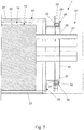
- Fig. 7 shows a schematic sectional view of the in Fig. 5 shown floor module 1. It can be seen that a flexible sealing element 35 made of an elastomer for sealing the heat exchanger receiving area 19 from the environment is arranged on the adapter component 28 or on the frame component 29 thereof. The sealing element 35 forming a sealing lip is partially received in a receptacle 36 on the frame component 29. Is the adapter component 28, as in Fig. 7 shown, attached to the flange sections 33 and 34, the sealing element 35 contacts the flange sections 33 and 34 for said sealing.
- Fig. 8 shows a schematic sectional view of the in Fig. 5 shown adapter component 28. In particular, the circumferential arrangement of the sealing element 35 can be seen.
- Fig. 9 shows a schematic and perspective view of the in Fig. 5 shown adapter component 28 before punching, through which the pipe bushings can be formed on the pipe bushing component 30.
- Fig. 10 shows a schematic and perspective view of the in Fig. 5 shown adapter component 28 after punching, whereby circular tube feedthroughs 26 have been formed on the stirring leadthrough component 30.
- Fig. 11 shows a further schematic and perspective representation of the in Fig. 5 shown adapter component 28 after punching, whereby 30-shaped pipe lead-throughs 26 have been formed on the stirring leadthrough component.
Landscapes
- Engineering & Computer Science (AREA)
- Textile Engineering (AREA)
- Detail Structures Of Washing Machines And Dryers (AREA)
- Drying Of Solid Materials (AREA)
- Heat-Exchange Devices With Radiators And Conduit Assemblies (AREA)
Description
- Die Erfindung betrifft ein Bodenmodul zum Halten einer Wärmepumpe eines Haushaltsgeräts zum Trocknen von Wäsche, aufweisend wenigstens einen Wärmetauscheraufnahmebereich zum zumindest teilweisen Aufnehmen wenigstens eines Wärmetauschers der Wärmepumpe, wenigstens einen Bauteilaufnahmebereich zum zumindest teilweisen Aufnehmen eines Verdichters und/oder einer Drossel der Wärmepumpe und wenigstens eine den Wärmetauscheraufnahmebereich zumindest teilweise von dem Bauteilaufnahmebereich trennende Trennwand, an der wenigstens eine Rohrdurchführung zum Durchführen einer Rohrleitung eines Kältemittelkreislaufs der Wärmepumpe angeordnet ist, wobei die Trennwand zumindest teilweise durch wenigstens ein die Rohrdurchführung aufweisendes, separat ausgebildetes Adapterbauteil gebildet ist, wobei das Adapterbauteil einen die Rohrdurchführung aufweisenden Durchführungsabschnitt aus nachgiebigen Kunststoff in Form eines Schaumstoffs oder eines Elastomers oder eines mit einer Folie umhüllten Montageschaums aufweist, und wobei das Adapterbauteil aus zwei aufeinanderliegenden Adapterteilen gebildet ist, wobei die Rohrdurchführung von beiden Adapterteilen gebildet ist.
- Des Weiteren betrifft die Erfindung ein Haushaltsgerät zum Trocknen von Wäsche, aufweisend wenigstens eine Wärmepumpe.
- Ein gattungsgemäßes Bodenmodul und ein gattungsgemäßes Haushaltsgerät gehen hervor aus der
DE 10 2014 216 485 A1 und derWO 2016/026832 A1 . - In Haushaltsgeräten zum Trocknen von Wäsche werden zur Verbesserung der Energieeffizienz Wärmepumpen verbaut. Je nach Bauart eines solchen Haushaltsgeräts werden unterschiedlich ausgebildete Wärmepumpen eingesetzt, die von einem Bodenmodul des Haushaltsgeräts an ihren jeweiligen bestimmungsgemäßen Einsatzpositionen gehalten werden. Insbesondere können die Wärmetauscher (Evaporator, Kondensator) von Wärmepumpen hinsichtlich ihrer Baugröße und/oder der Anordnung der Zulaufanschlüsse und der Ablaufanschlüsse der Wärmetauscher, an denen Rohrleitungen des Kältemittelkreislaufs der Wärmepumpe anschließbar sind, unterschiedlich ausgebildet sein. Zudem können die Wärmetauscher je nach Bauart des Haushaltsgeräts an verschiedenen Einsatzpositionen angeordnet sein.
- Ein Bodenmodul umfasst üblicherweise ein Modulgehäuse mit einem Wärmetauscheraufnahmebereich zum Aufnehmen der Wärmetauscher der Wärmepumpe. Der Wärmetauscheraufnahmebereich ist an einen Prozessluftkreislauf des Haushaltsgeräts angeschlossen und gegenüber der Umgebung abgedichtet. Insbesondere ist der Wärmetauscheraufnahmebereich über eine Trennwand von einem Bauteilaufnahmebereich des Bodenmoduls getrennt, der zur Aufnahme eines Verdichters und/oder einer Drossel der Wärmepumpe dient. Um die Wärmetauscher und den Verdichter bzw. die Drossel in einen gemeinsamen Kältemittelkreislauf zu integrieren, sind Rohrleitungen des Kältemittelkreislaufs durch die Trennwand geführt, an der hierzu Rohrdurchführungen ausgebildet sind. Die Dimensionierung und Positionierung der Rohrdurchführungen ist an die Dimensionierung und Positionierung der durch die Trennwand geführten Rohrleitungsabschnitte angepasst. Bei einer monolithisch mit dem Modulgehäuse verbundenen Trennwand ist es daher erforderlich, für jede Ausgestaltung einer Wärmepumpe ein spezielles Modulgehäuse herzustellen, dessen Rohrdurchführungen an geeigneten Positionen angeordnet sind. Herkömmlich kann es zudem erforderlich sein, die Ausgestaltung einer Wärmepumpe bzw. von deren Kältemittelkreislauf an die jeweilig gegebenen Bodenmodule anzupassen, was den Gestaltungsspielraum beim Entwerfen einer Wärmepumpe stark einschränkt und darüber hinaus mit Effektivitätsnachteilen verbunden sein kann.
- Aus der
DE 10 2014 216 485 A1 und derWO 2016/026832 A1 ist ein Bodenmodul bekannt, bei dem die Trennwand zumindest teilweise durch wenigstens ein zumindest eine Rohrdurchführung aufweisendes, separat ausgebildetes Adapterbauteil gebildet ist. Durch die Wahl eines für die jeweilige Ausgestaltung der zu verbauenden Wärmepumpe geeigneten Adapterbauteils und die Verbindung dieses Adapterbauteil mit der übrigen Trennwand kann das Bodenmodul unter deutlich geringerem Aufwand an die Ausgestaltung der Wärmepumpe angepasst werden. Diese Anpassung des Bodenmoduls an die jeweilige Ausgestaltung der Wärmepumpe kann kurz vor der Montage eines Bodenmoduls bzw. eines damit ausgestatteten Haushaltsgeräts durch den Einsatz eines an die Ausgestaltung der Wärmepumpe angepassten Adapterbauteils erfolgen. Das Bodenmodul kann somit auf einfache Art und Weise sowohl an bereits vorhandene Ausgestaltungen von Wärmepumpen als auch an zukünftige Ausgestaltungen von Wärmepumpen angepasst werden. Insbesondere kann das Bodenmodul durch die Wahl eines geeigneten Adapterbauteils auf einfache Art und Weise an breiter und/oder höher ausgebildete Wärmetauscher bzw. an die Ausgestaltung des jeweilig erforderlichen Kältemittelkreislaufs angepasst werden. Bei Verwendung von solchen Bodenmodulen können ein Transport, eine Verwaltung und eine Lagerhaltung von kompletten Bodenmodulen entfallen. Es müssen lediglich die deutlich kleineren Adapterbauteile in verschiedenen Varianten hergestellt, gelagert und transportiert werden. Die Verwendung von solchen Bodenmodulen macht zudem ein schnelles Reagieren eines Herstellers von Bodenmodulen auf unterschiedliche Marktanforderungen möglich. -
EP 2 881 514 A1 offenbart einen Wäschetrockner mit einer Wärmepumpeneinrichtung, deren Wärmetauscher ein durch Lamellen geführtes Rohrschlaufensystem aufweist, wobei der Wärmetauscher zur Kühlung und/oder zur Erwärmung eines Prozessluftstromes in einem Strömungskanal mit seitlich angeordneten Abschirmungen angeordnet ist. Die Abschirmungen bestehen aus Formkörperelementen, die den im Strömungskanal seitlich liegenden freien Bauraum bzw. den seitlichen Hohlraum des Wärmetauschers im Wesentlichen ausfüllen. -
EP 2 915 916 A1 offenbart einen Wäschetrockner mit einer Wärmepumpeneinrichtung, deren Wärmetauscher in einem Strömungskanal angeordnet ist, wobei der Wärmetauscher mit einem Kompressor über Kältemittelrohre verbunden ist, die durch in der Wand des Strömungskanals angeordneter Öffnungen verlegt sind. Der Strömungskanal ist aus Teilschalen gebildet, wobei die Kältemittelrohre im Verbindungsbereich der Schalen in dafür vorgesehenen Teilöffnungen an den Teilschalen angeordnet sind. An den Teilöffnungen der Teilschalen sind Profilierungen in Form einer Auflage und eines Bogens angeformt, die sich quer zur Ebene der Wand des Strömungskanals erstrecken. - Eine Aufgabe der Erfindung ist es, den mit der Herstellung von Haushaltsgeräten zum Trocknen von Wäsche verbundenen Aufwand zu reduzieren.
- Diese Aufgabe wird durch die Gegenstände der unabhängigen Patentansprüche gelöst. Vorteilhafte fakultative Ausgestaltungen sind insbesondere in den abhängigen Patentansprüchen angegeben, die jeweils für sich genommen oder in verschiedener Kombination untereinander einen weiterbildenden, insbesondere auch bevorzugten oder vorteilhaften, Aspekt der Erfindung darstellen können.
- Ein erfindungsgemäßes Bodenmodul zum Halten einer Wärmepumpe eines Haushaltsgeräts zum Trocknen von Wäsche umfasst wenigstens einen Wärmetauscheraufnahmebereich zum zumindest teilweisen Aufnehmen wenigstens eines Wärmetauschers der Wärmepumpe, wenigstens einen Bauteilaufnahmebereich zum zumindest teilweisen Aufnehmen eines Verdichters und/oder einer Drossel der Wärmepumpe und wenigstens eine den Wärmetauscheraufnahmebereich zumindest teilweise von dem Bauteilaufnahmebereich trennende Trennwand, an der wenigstens eine Rohrdurchführung zum Durchführen einer Rohrleitung eines Kältemittelkreislaufs der Wärmepumpe angeordnet ist. Die Trennwand ist zumindest teilweise durch wenigstens ein die Rohrdurchführung aufweisendes, separat ausgebildetes Adapterbauteil gebildet. Das Adapterbauteil umfasst einen die Rohrdurchführung aufweisenden Durchführungsabschnitt aus einem nachgiebigen Kunststoff in Form eines Schaumstoffs oder eines Elastomers oder eines mit einer Folie umhüllten Montageschaums. Das Adapterbauteil ist aus zwei aufeinanderliegenden Adapterteilen gebildet, wobei die Rohrdurchführung von beiden Adapterteilen gebildet ist. Die Adapterteile sind an der Rohrdurchführung mit Schlitzen versehen.
- Erfindungsgemäß ist der die Rohrdurchführung umgebende Durchführungsabschnitt des Adapterbauteils nachgiebig bzw. elastisch verformbar ausgebildet, wodurch Variationen der Positionierung und der Dimensionierung des durch die Rohrdurchführung geführten Leitungsabschnitts der Rohrleitung mit ein und demselben Adapterbauteil aufgefangen werden können, ohne dass bauliche Veränderungen an dem Adapterbauteil vorgenommen werden müssen. Durch die Nachgiebigkeit des Durchführungsabschnitts kann auch eine Schiefstellung des Leitungsabschnitts mit ein und demselben Adapterbauteil aufgefangen werden. Um diese Variationen auffangen zu können, müssen nicht, wie herkömmlich, entweder ganze Modulgehäuse oder Adapterbauteile speziell hergestellt und eingesetzt werden. Die Ausgestaltung der Trennwand wird hierdurch weitestgehend unabhängig von der jeweiligen Ausgestaltung der zu verbauenden Wärmepumpe. Es müssen statt spezieller Modulgehäuse oder spezieller formsteifer Adapterbauteile lediglich die erfindungsgemäßen Adapterbauteile als Gleichteile hergestellt, gelagert und transportiert werden. Dies stellt einen erheblichen wirtschaftlichen Vorteil dar. Dies ist insbesondere dadurch möglich, da die äußeren Schnittstellen des Adapterbauteils zum Modulgehäuse immer gleich ausgebildet sein können.
- Durch die Nachgiebigkeit des die Rohrdurchführung umgebenden Durchführungsabschnitts kann sich dieser bei geeigneter Abstimmung zwischen der Querschnittsfläche der Rohrdurchführung und der Querschnittsfläche des dadurch geführten Leitungsabschnitts radial außen an den Leitungsabschnitt anschmiegen und hierdurch den Wärmetauscheraufnahmebereich gegenüber der Umgebung abdichten. Zu dieser Abdichtung sind somit kein zusätzliches separates Dichtmittel und keine aufzubringenden Montagekräfte erforderlich.
- Der Begriff "Nachgiebigkeit" bedeutet im Rahmen der Erfindung, dass sich der Durchführungsabschnitt des Adapterbauteils durch einen körperlichen Kontakt mit der wenigstens einen Rohrleitung elastisch verformt, um eine Lagetoleranz zwischen dem Adapterbauteil und der Rohrleitung ausgleichen zu können. Der Durchführungsabschnitt passt sich hierbei zwangsläufig optimal an die Lage und Formgebung der Rohrleitung an, was insbesondere hinsichtlich der erforderlichen Abdichtung des Wärmetauscheraufnahmebereichs gegenüber der Umgebung von Vorteil ist. Ein solcher Toleranzausgleich ist mit einem insgesamt nicht nachgiebigen bzw. vollständig formsteifen Adapterbauteil nicht realisierbar. Stattdessen käme es bei einem derartigen herkömmlichen Adapterbauteil bei einem Vorliegen von Lagetoleranzen eher zu einer ungewünschten Verformung der Rohrleitung.
- Das Adapterbauteil kann auch vollständig aus dem nachgiebigen Kunststoff bzw. durch den Durchführungsabschnitt ausgebildet sein. Das Adapterbauteil kann über wenigstens ein zerstörungsfrei lösbares Verbindungsmittel mit der übrigen Trennwand verbindbar sein. An dem Durchführungsabschnitt bzw. dem Adapterbauteil können entsprechend auch zwei oder mehrere Rohrdurchführungen zum Durchführen von jeweils einer Rohrleitung des Kältemittelkreislaufs der Wärmepumpe ausgebildet sein. Dabei fassen die Adapterteile das durchzuführende Rohr jeweils zwischen sich ein.
- Die Trennwand kann teilweise oder vollständig durch das separat ausgebildete Adapterbauteil gebildet sein. Die Trennwand kann zumindest teilweise auch durch zwei oder mehrere zu einer Adapterbaugruppe miteinander kombinierte Adapterbauteile gebildet sein.
- Der Wärmetauscheraufnahmebereich kann zur Aufnahme von einem oder beiden Wärmetauschern der Wärmepumpe ausgebildet sein. Der Bauteilaufnahmebereich kann sich entlang eines Teils der Länge des Wärmetauscheraufnahmebereichs oder über die gesamte Länge des Wärmetauscheraufnahmebereichs erstrecken.
- Der Durchführungsabschnitt oder das gesamte Adapterbauteil kann durch einen nachgiebigen Schaumstoff bzw. ein nachgiebiges Schaumstoffformbauteil gebildet sein.Es kann der Durchführungsabschnitt oder das gesamte Adapterbauteil als ein-, zwei- oder mehrteiliges Gummiformbauteil ausgebildet sein.
- Bei der Montage einer Wärmetauscherabdeckung an dem Wärmetauscheraufnahmebereich kann durch die Expansion des Montageschaums die Dichtwirkung des Durchführungsabschnitts erzeugt werden. Durch die Folie und den Montageschaum wird ein Kunststoffverbund ausgebildet, der im Rahmen der Erfindung vereinfacht als Kunststoff bezeichnet wird.
- Die Schlitze an den Rohrdurchführungen der Adapterteile erleichtern das Verformen der Adapterteile beim Durchführen des Rohrs und machen eventuell ein Vorformen der Rohrdurchführungen entbehrlich - insbesondere dann, wenn für die Adapterteile ein entsprechend nachgiebiger und verformbarer Schaumstoff verwendet wird. Dies mag die Herstellung der Adapterteile vereinfachen und die Montage der Rohre in den Durchführungen zwischen den Adapterteilen sicherer und auch einfacher machen.
- Nach einer weiteren vorteilhaften Ausgestaltung ist an dem Adapterbauteil wenigstens ein flexibles Dichtelement zum Abdichten des Wärmetauscheraufnahmebereichs gegenüber einer Umgebung angeordnet. Das flexible Dichtelement kann umlaufend an dem Adapterbauteil angeordnet sein. Das Dichtelement kann beispielsweise aus einem Elastomer hergestellt sein. Das Dichtelement kann separat oder monolithisch mit einem Abschnitt des Adapterbauteils hergestellt werden.
- Eine weitere vorteilhafte Ausgestaltung sieht vor, dass das Bodenmodul ein Modulgehäuse mit einem bodenseitigen Aufnahmebauteil, an dem der Wärmetauscheraufnahmebereich und der Bauteilaufnahmebereich ausgebildet sind, und einer den Wärmetauscheraufnahmebereich bodenabseitig verschließenden Wärmetauscherabdeckung aufweist, wobei an einem mit dem Aufnahmebauteil verbundenen Wandabschnitt der Trennwand ein erstes Rahmenelement und an der Wärmetauscherabdeckung ein zweites Rahmenelement angeordnet sind, und wobei die Rahmenelemente einen Rahmen zur formschlüssigen Aufnahme des Adapterbauteils bilden. Hierbei kann das gesamte Adapterbauteil aus dem nachgiebigen Kunststoff als Formbauteil hergestellt sein.
- Nach einer alternativen Ausgestaltung, welche jedoch nicht Teil der beanspruchten Erfindung ist, umfasst das Adapterbauteil ein mit der übrigen Trennwand verbindbares, formsteifes Rahmenbauteil und ein in das Rahmenbauteil eingefasstes Rohrdurchführungsbauteil, wobei das Rohrdurchführungsbauteil aus dem nachgiebigen Kunststoff hergestellt ist. Das Rohrdurchführungsbauteil bildet den Durchführungsabschnitt des Adapterbauteils aus. Das Rahmenbauteil kann zur Fixierung des Adapterbauteils an dem Modulgehäuse verwendet werden. Das Rahmenbauteil kann als runder oder eckiger Rahmen ausbildet sein. Das Adapterbauteil bzw. das Rohrdurchführungsbauteil kann hierbei flächig und vergleichsweise groß ausgebildet sein, wodurch eine große Fläche zur Durchführung der Rohrleitung zur Verfügung steht. Das Rohrdurchführungsbauteil kann aus einem thermoplastischen Elastomer oder einem ähnlichen 2K-Werkstoff hergestellt sein. Das Adapterbauteil kann, abgesehen von den Rohrdurchführungen, als Gleichteil hergestellt werden.
- Vorteilhafterweise ist das Rahmenbauteil aus einem thermoplastischen Kunststoff hergestellt. An dem somit aus einem Hartkunststoff hergestellten Rahmenbauteil kann anschließend das Rohrdurchführungsbauteil angeordnet werden. Bei der Herstellung des Rahmenbauteils kann in diesen ein elastomerer Werkstoff eingespritzt werden, um ein flexibles Dichtelement auszubilden, das zur Verbesserung der Abdichtung des Wärmetauscheraufnahmebereichs zwischen dem Rahmenbauteil und dem Modulgehäuse angeordnet ist.
- Es ist des Weiteren von Vorteil, wenn das Rahmenbauteil über wenigstens eine Schraubverbindung oder wenigstens eine Schnappverbindung mit der übrigen Trennwand verbunden ist. Dies macht eine einfache Montage und Demontage des Adapterbauteils möglich.
- Gemäß einer weiteren vorteilhaften Ausgestaltung ist die Rohrdurchführung durch einen Stanzvorgang hergestellt. Hierdurch kann das Adapterbauteil unmittelbar vor seiner Montage an dem Modulgehäuse vorgestanzt und hierdurch auf einfache Art und Weise an die jeweilige Ausgestaltung der Wärmepumpe angepasst werden, was den Logistikaufwand reduziert. Die Stanzung kann direkt an der Montagelinie vorgenommen werden. Anschließend kann das Adapterbauteil bzw. das Rohrdurchführungsbauteil auf ein Rohrende der Rohrleitung geschoben werden. Dieses Aufschieben kann vor der Montage der Wärmetauscher an dem Modulgehäuse vorgenommen werden. Die Stanzung ist so gestaltet, dass eine umlaufende Umschließung des durch die Rohrdurchführung geführten Leitungsabschnitts gewährleistet ist. Der Leitungsabschnitt durchstößt die vorgestanzte Rohrdurchführung ähnlich einer Membran. Das Rohrdurchführungsbauteil legt sich radial außen umlaufend an dem Leitungsabschnitt an.
- Ein erfindungsgemäßes Haushaltsgerät zum Trocknen von Wäsche umfasst wenigstens eine Wärmepumpe und wenigstens ein Bodenmodul nach der vorgenannten erfindungsgemäßen Ausgestaltung.
- Mit dem Haushaltsgerät sind die oben mit Bezug auf das Bodenmodul genannten Vorteile entsprechend verbunden. Das Hausgerät kann beispielsweise als Wäschetrockner oder Waschtrockner ausgebildet sein.
- Im Folgenden wird die Erfindung unter Bezugnahme auf die Figuren der beigefügten Zeichnung anhand bevorzugter Ausführungsformen exemplarisch erläutert. Es zeigen:
- Fig. 1
- eine schematische und perspektivische Darstellung eines Ausführungsbeispiels für ein Bodenmodul;
- Fig. 2
- eine schematische und perspektivische Detaildarstellung des in
Fig. 1 gezeigten Bodenmoduls; - Fig. 3
- eine weitere schematische und perspektivische Detaildarstellung des in
Fig. 1 gezeigten Bodenmoduls; - Fig. 4
- eine weitere schematische und perspektivische Detaildarstellung des in
Fig. 1 gezeigten Bodenmoduls; - Fig. 5
- eine schematische und perspektivische Darstellung eines weiteren Ausführungsbeispiels für ein Bodenmodul, wobei dieses Ausführungsbeispiel nicht Teil der beanspruchten Erfindung ist.
- Fig. 6
- eine schematische und perspektivische Explosionsdarstellung des in
Fig. 5 gezeigten Bodenmoduls; - Fig. 7
- eine schematische Schnittdarstellung des in
Fig. 5 gezeigten Bodenmoduls; - Fig. 8
- eine schematische Schnittdarstellung des in
Fig. 5 gezeigten Adapterbauteils; - Fig. 9
- eine schematische und perspektivische Darstellung des in
Fig. 5 gezeigten Adapterbauteils vor einer Stanzung; - Fig. 10
- eine schematische und perspektivische Darstellung des in
Fig. 5 gezeigten Adapterbauteils nach einer Stanzung; und - Fig. 11
- eine weitere schematische und perspektivische Darstellung des in
Fig. 5 gezeigten Adapterbauteils nach einer Stanzung. - In den Figuren sind gleiche bzw. funktionsgleiche Bauteile mit denselben Bezugszeichen versehen.
-
Fig. 1 zeigt eine schematische und perspektivische Darstellung eines Ausführungsbeispiels für ein Bodenmodul 1 zum Halten einer nicht gezeigten Wärmepumpe eines Haushaltsgeräts 15 zum Trocknen von Wäsche. - Das Bodenmodul 1 umfasst einen Wärmetauscheraufnahmebereich 2 zum Aufnehmen von nicht gezeigten Wärmetauschern der Wärmepumpe und einen Bauteilaufnahmebereich 3 zum zumindest teilweisen Aufnehmen eines nicht gezeigten Verdichters und/oder einer nicht gezeigten Drossel der Wärmepumpe. Das Bodenmodul 1 umfasst hierzu ein Modulgehäuse 4 mit einem bodenseitigen Aufnahmebauteil 5, an dem der Wärmetauscheraufnahmebereich 2 und der Bauteilaufnahmebereich 3 ausgebildet sind, und einer den Wärmetauscheraufnahmebereich 2 bodenabseitig verschließenden Wärmetauscherabdeckung 6, deren Aufbau aus
Fig. 2 deutlicher wird. Das Bodenmodul 1 umfasst des Weiteren eine den Wärmetauscheraufnahmebereich 2 von dem Bauteilaufnahmebereich 3 trennende Trennwand 7, an der vier Rohrdurchführungen 8 zum Durchführen von jeweils einer nicht gezeigten Rohrleitung eines Kältemittelkreislaufs der Wärmepumpe angeordnet sind. Die Rohrdurchführungen 8 können beispielsweise durch einen Stanzvorgang hergestellt werden. - Die Trennwand 7 ist teilweise durch ein die Rohrdurchführungen 8 aufweisendes, separat ausgebildetes Adapterbauteil 9 gebildet. Das Adapterbauteil 9 besteht vollständig aus einem nachgiebigen Kunststoff, umfasst also einen die Rohrdurchführungen 8 aufweisenden Durchführungsabschnitt aus einem nachgiebigen Kunststoff. Der nachgiebige Kunststoff kann ein Schaumstoff, ein Elastomer oder ein mit einer Folie umhüllter Montageschaum sein. Das Adapterbauteil 9 ist als zweiteiliger Formkörper ausgebildet, wobei die beiden Adapterteile 10 und 11 entlang einer im Wesentlichen horizontal verlaufenden Trennebene 12 getrennt sind. An einem mit dem Aufnahmebauteil 5 verbundenen Wandabschnitt der Trennwand 7 ist ein erstes Rahmenelement 13 und an der Wärmetauscherabdeckung 6 ist ein zweites Rahmenelement 14 angeordnet, wobei die Rahmenelemente 13 und 14 einen Rahmen zur formschlüssigen Aufnahme des Adapterbauteils 9 bilden. Der mit dem Adapterbauteil 9 verbundene Wandabschnitt der Trennwand 7 wird durch ein separates Wandbauteil 16 gebildet, das formschlüssig mit der übrigen Trennwand 17 verbunden ist. Das Wandbauteil 16 kann separat ausgebildet oder an das Aufnahmebauteil 5 angespritzt sein.
-
Fig. 2 zeigt eine schematische und perspektivische Detaildarstellung des inFig. 1 gezeigten Bodenmoduls 1. Es sind lediglich die Wärmetauscherabdeckung 6, das Adapterbauteil 9 und das Wandbauteil 16 gezeigt. -
Fig. 3 zeigt eine weitere schematische und perspektivische Detaildarstellung des inFig. 1 gezeigten Bodenmoduls 1. Es sind lediglich das Adapterbauteil 9 und das Wandbauteil 16 gezeigt. -
Fig. 4 zeigt eine weitere schematische und perspektivische Detaildarstellung des inFig. 1 gezeigten Bodenmoduls 1. Es ist lediglich das quaderförmige Adapterbauteil 9 gezeigt. Das Adapterbauteil 9 ist aus zwei aufeinanderliegenden Adapterteilen 10 und 11 gebildet, wobei die Rohrdurchführungen 8 von beiden Adapterteilen 10 und 11 - hier jeweils hälftig - gebildet sind. An jeder Rohrdurchführung 8 ist jedes Adapterteil 10 oder 11 mit Schlitzen 38 versehen. Dadurch kann sich jedes Adapterteil 10 oder 11 besser an das durch die Rohrdurchführung 8 geführte Rohr anschmiegen. Gegebenenfalls kann davon abgesehen werden, zusätzlich zu den Schlitzen die Rohrdurchführung 8 vorzuformen, insbesondere dann, wenn die Adapterteile 10 und 11 aus einem entsprechend nachgiebigen und verformbaren Schaumstoff bestehen. -
Fig. 5 zeigt eine schematische und perspektivische Darstellung eines weiteren Ausführungsbeispiels für ein Bodenmodul 1 zum Halten einer Wärmepumpe 18 eines Haushaltsgeräts 15 zum Trocknen von Wäsche, wobei dieses Ausführungsbeispiel nicht Teil der beanspruchten Erfindung ist. - Das Bodenmodul 1 umfasst einen Wärmetauscheraufnahmebereich 19 zum Aufnehmen von Wärmetauschern 20 der Wärmepumpe 18, von denen in
Fig. 5 nur ein Wärmetauscher 20 gezeigt ist, und einen Bauteilaufnahmebereich 21 zum zumindest teilweisen Aufnehmen eines nicht gezeigten Verdichters und/oder einer nicht gezeigten Drossel der Wärmepumpe 18. Das Bodenmodul 1 umfasst hierzu ein Modulgehäuse 22 mit einem bodenseitigen Aufnahmebauteil 23, an dem der Wärmetauscheraufnahmebereich 19 und der Bauteilaufnahmebereich 21 ausgebildet sind, und einer den Wärmetauscheraufnahmebereich 19 bodenabseitig verschließenden Wärmetauscherabdeckung 24. Das Bodenmodul 1 umfasst des Weiteren eine den Wärmetauscheraufnahmebereich 19 von dem Bauteilaufnahmebereich 21 trennende Trennwand 25, an der vier Rohrdurchführungen 26 zum Durchführen von jeweils einer Rohrleitung 27 eines Kältemittelkreislaufs der Wärmepumpe 18 angeordnet sind. Die Rohrdurchführungen 26 können beispielsweise durch einen Stanzvorgang hergestellt werden. - Die Trennwand 25 ist teilweise durch ein die Rohrdurchführungen 26 aufweisendes, separat ausgebildetes Adapterbauteil 28 gebildet. Das Adapterbauteil 28 umfasst ein mit der übrigen Trennwand 37 verbundenes, formsteifes Rahmenbauteil 29 aus einem thermoplastischen Kunststoff und ein in das Rahmenbauteil 29 eingefasstes Rohrdurchführungsbauteil 30, wobei das Rohrdurchführungsbauteil 30 aus einem nachgiebigen Kunststoff hergestellt ist. Folglich umfasst das Adapterbauteil 28 einen die Rohrdurchführungen 26 aufweisenden Durchführungsabschnitt aus einem nachgiebigen Kunststoff. Das Rahmenbauteil 29 kann über wenigstens eine nicht gezeigte Schraubverbindung oder wenigstens eine nicht gezeigte Schnappverbindung mit der übrigen Trennwand 37 verbunden sein, wozu an dem Rahmenbauteil 29 vier nach außen weisende Befestigungslaschen 31 angeordnet sind. Der nachgiebige Kunststoff kann ein Schaumstoff oder ein Elastomer sein.
-
Fig. 6 zeigt eine schematische und perspektivische Explosionsdarstellung des inFig. 5 gezeigten Bodenmoduls 1. Es sind insbesondere beide Wärmetauscher 20 und 32 der Wärmepumpe 18 zu sehen. Zudem ist zu sehen, dass an der Wärmetauscherabdeckung 24 und dem bodenseitigen Aufnahmebauteil 23 jeweils ein Flanschabschnitt 33 bzw. 34 angeordnet ist, an denen das Adapterbauteil 28 bzw. dessen Rahmenbauteil 29 befestigbar ist. -
Fig. 7 zeigt eine schematische Schnittdarstellung des inFig. 5 gezeigten Bodenmoduls 1. Es ist zu sehen, dass an dem Adapterbauteil 28 bzw. an dessen Rahmenbauteil 29 ein flexibles Dichtelement 35 aus einem Elastomer zum Abdichten des Wärmetauscheraufnahmebereichs 19 gegenüber der Umgebung angeordnet ist. Das eine Dichtlippe ausbildende Dichtelement 35 ist teilweise in einer Aufnahme 36 an dem Rahmenbauteil 29 aufgenommen. Ist das Adapterbauteil 28, wie inFig. 7 gezeigt, an den Flanschabschnitten 33 und 34 befestigt, kontaktiert das Dichtelement 35 zur genannten Abdichtung die Flanschabschnitte 33 und 34. -
Fig. 8 zeigt eine schematische Schnittdarstellung des inFig. 5 gezeigten Adapterbauteils 28. Es ist insbesondere die umlaufende Anordnung des Dichtelements 35 zu sehen. -
Fig. 9 zeigt eine schematische und perspektivische Darstellung des inFig. 5 gezeigten Adapterbauteils 28 vor einer Stanzung, durch welche die Rohrdurchführungen an dem Rohrdurchführungsbauteil 30 ausgebildet werden können. -
Fig. 10 zeigt eine schematische und perspektivische Darstellung des inFig. 5 gezeigten Adapterbauteils 28 nach einer Stanzung, wodurch an dem Rührdurchführungsbauteil 30 kreisförmige Rohrdurchführungen 26 ausgebildet worden sind. -
Fig. 11 zeigt eine weitere schematische und perspektivische Darstellung des inFig. 5 gezeigten Adapterbauteils 28 nach einer Stanzung, wodurch an dem Rührdurchführungsbauteil 30 sternförmige Rohrdurchführungen 26 ausgebildet worden sind. -
- 1
- Bodenmodul
- 2
- Wärmetauscheraufnahmebereich
- 3
- Bauteilaufnahmebereich
- 4
- Modulgehäuse
- 5
- bodenseitiges Aufnahmebauteil
- 6
- Wärmetauscherabdeckung
- 7
- Trennwand
- 8
- Rohrdurchführung
- 9
- Adapterbauteil
- 10
- Adapterteil
- 11
- Adapterteil
- 12
- Trennebene
- 13
- Rahmenelement
- 14
- Rahmenelement
- 15
- Haushaltsgerät
- 16
- Wandbauteil
- 17
- übrige Trennwand
- 18
- Wärmepumpe
- 19
- Wärmetauscheraufnahmebereich
- 20
- Wärmetauscher
- 21
- Bauteilaufnahmebereich
- 22
- Modulgehäuse
- 23
- bodenseitiges Aufnahmebauteil
- 24
- Wärmetauscherabdeckung
- 25
- Trennwand
- 26
- Rohrdurchführung
- 27
- Rohrleitung
- 28
- Adapterbauteil
- 29
- Rahmenbauteil
- 30
- Rohrdurchführungsbauteil
- 31
- Befestigungslasche
- 32
- Wärmetauscher
- 33
- Flanschabschnitt von 24
- 34
- Flanschabschnitt von 23
- 35
- Dichtelement
- 36
- Aufnahme von 29
- 37
- übrige Trennwand
- 38
- Schlitze im Adapterteil
Claims (8)
- Bodenmodul (1) zum Halten einer Wärmepumpe (18) eines Haushaltsgeräts (15) zum Trocknen von Wäsche, aufweisend- wenigstens einen Wärmetauscheraufnahmebereich (2, 19) zum zumindest teilweisen Aufnehmen wenigstens eines Wärmetauschers (20, 32) der Wärmepumpe (18),- wenigstens einen Bauteilaufnahmebereich (3, 21) zum zumindest teilweisen Aufnehmen eines Verdichters und/oder einer Drossel der Wärmepumpe (18) und- wenigstens eine den Wärmetauscheraufnahmebereich (2, 19) zumindest teilweise von dem Bauteilaufnahmebereich (3, 21) trennende Trennwand (7, 25), an der wenigstens eine Rohrdurchführung (8, 26) zum Durchführen einer Rohrleitung (27) eines Kältemittelkreislaufs der Wärmepumpe (18) angeordnet ist,- wobei die Trennwand (7, 25) zumindest teilweise durch wenigstens ein die Rohrdurchführung (8, 26) aufweisendes, separat ausgebildetes Adapterbauteil (9, 28) gebildet ist,- wobei das Adapterbauteil (9, 28) einen die Rohrdurchführung (8, 26) aufweisenden Durchführungsabschnitt aus nachgiebigen Kunststoff in Form eines Schaumstoffs oder eines Elastomers oder eines mit einer Folie umhüllten Montageschaums aufweist,dadurch gekennzeichnet, dass
das Adapterbauteil (9, 28) aus zwei aufeinanderliegenden Adapterteilen (10, 11) gebildet ist, wobei die Rohrdurchführung (8, 26) von beiden Adapterteilen (10, 11) gebildet ist,- wobei die Adapterteile (10,11) an der Rohrdurchführung (8, 26) mit Schlitzen (38) versehen sind. - Bodenmodul (1) nach Anspruch 1, dadurch gekennzeichnet, dass an dem Adapterbauteil (28) wenigstens ein flexibles Dichtelement (35) zum Abdichten des Wärmetauscheraufnahmebereichs (19) gegenüber der Umgebung angeordnet ist.
- Bodenmodul (1) nach Anspruch 1 oder 2, gekennzeichnet durch ein Modulgehäuse (4, 22) mit einem bodenseitigen Aufnahmebauteil (5, 23), an dem der Wärmetauscheraufnahmebereich (2, 19) und der Bauteilaufnahmebereich (3, 21) ausgebildet sind, und einer den Wärmetauscheraufnahmebereich (2, 19) bodenabseitig verschließenden Wärmetauscherabdeckung (6, 24), wobei an einem mit dem Aufnahmebauteil (5) verbundenen Wandabschnitt der Trennwand (7) ein erstes Rahmenelement (13) und an der Wärmetauscherabdeckung (6) ein zweites Rahmenelement (14) angeordnet sind, und wobei die Rahmenelemente (13, 14) einen Rahmen zur formschlüssigen Aufnahme des Adapterbauteils (9) bilden.
- Bodenmodul (1) nach Anspruch 1 oder 2, dadurch gekennzeichnet, dass das Adapterbauteil (28) ein mit der übrigen Trennwand (37) verbindbares, formsteifes Rahmenbauteil (29) und ein in das Rahmenbauteil (29) eingefasstes Rohrdurchführungsbauteil (30) aufweist, wobei das Rohrdurchführungsbauteil (30) aus dem nachgiebige Kunststoff hergestellt ist.
- Bodenmodul (1) nach Anspruch 4, dadurch gekennzeichnet, dass das Rahmenbauteil (29) aus einem thermoplastischen Kunststoff hergestellt ist.
- Bodenmodul (1) nach Anspruch 4 oder 5, dadurch gekennzeichnet, dass das Rahmenbauteil (29) über wenigstens eine Schraubverbindung oder wenigstens eine Schnappverbindung mit der übrigen Trennwand (37) verbunden ist.
- Bodenmodul (1) nach einem der Ansprüche 1 bis 6, dadurch gekennzeichnet, dass die Rohrdurchführung (8, 26) durch einen Stanzvorgang hergestellt ist.
- Haushaltsgerät (15) zum Trocknen von Wäsche, aufweisend wenigstens eine Wärmepumpe (18), gekennzeichnet durch wenigstens ein Bodenmodul (1) nach einem der Ansprüche 1 bis 7.
Priority Applications (1)
| Application Number | Priority Date | Filing Date | Title |
|---|---|---|---|
| PL17707521T PL3443157T3 (pl) | 2016-04-14 | 2017-02-24 | Moduł podstawy do urządzenia gospodarstwa domowego do suszenia prania i urządzenie gospodarstwa domowego |
Applications Claiming Priority (2)
| Application Number | Priority Date | Filing Date | Title |
|---|---|---|---|
| DE102016206229.8A DE102016206229A1 (de) | 2016-04-14 | 2016-04-14 | Bodenmodul für ein Haushaltsgerät zum Trocknen von Wäsche sowie Haushaltsgerät |
| PCT/EP2017/054267 WO2017178143A1 (de) | 2016-04-14 | 2017-02-24 | Bodenmodul für ein haushaltsgerät zum trocknen von wäsche sowie haushaltsgerät |
Publications (2)
| Publication Number | Publication Date |
|---|---|
| EP3443157A1 EP3443157A1 (de) | 2019-02-20 |
| EP3443157B1 true EP3443157B1 (de) | 2020-01-29 |
Family
ID=58185516
Family Applications (1)
| Application Number | Title | Priority Date | Filing Date |
|---|---|---|---|
| EP17707521.5A Active EP3443157B1 (de) | 2016-04-14 | 2017-02-24 | Bodenmodul für ein haushaltsgerät zum trocknen von wäsche sowie haushaltsgerät |
Country Status (5)
| Country | Link |
|---|---|
| EP (1) | EP3443157B1 (de) |
| CN (1) | CN108884624B (de) |
| DE (1) | DE102016206229A1 (de) |
| PL (1) | PL3443157T3 (de) |
| WO (1) | WO2017178143A1 (de) |
Families Citing this family (2)
| Publication number | Priority date | Publication date | Assignee | Title |
|---|---|---|---|---|
| TR201721751A2 (tr) * | 2017-12-26 | 2019-07-22 | Arcelik As | Isi pompali ürünlerde farkli ti̇p eşanjör kullanilmasina olanak sağlayan bi̇r si̇stem |
| CN112095280B (zh) * | 2020-08-31 | 2024-10-29 | 天津海尔洗涤电器有限公司 | 滚筒洗衣机及其管路固定部件 |
Family Cites Families (11)
| Publication number | Priority date | Publication date | Assignee | Title |
|---|---|---|---|---|
| DE102008009782A1 (de) * | 2008-02-19 | 2009-08-27 | BSH Bosch und Siemens Hausgeräte GmbH | Hausgerät zum Trocknen eines feuchten Gutes mit einer Kühlanordnung und einer Heizanordnung |
| DE102008009784A1 (de) * | 2008-02-19 | 2009-08-27 | BSH Bosch und Siemens Hausgeräte GmbH | Hausgerät zum Trocknen eines feuchten Gutes mit einer Kühlanordnung und einer Heizanordnung |
| EP2423376B1 (de) * | 2010-08-25 | 2013-04-24 | Electrolux Home Products Corporation N.V. | Wäschebehandlungsmaschine |
| EP2458072A1 (de) * | 2010-11-29 | 2012-05-30 | Electrolux Home Products Corporation N.V. | Wäschetrockner |
| PL2471994T3 (pl) * | 2011-01-04 | 2019-12-31 | Electrolux Home Products Corporation N.V. | Urządzenie do suszenia materiałów pranych |
| EP2527526B1 (de) * | 2011-05-27 | 2014-07-23 | Electrolux Home Products Corporation N.V. | Wäschetrockner mit Drehtrommel |
| EP2708638A1 (de) * | 2012-09-13 | 2014-03-19 | Electrolux Home Products Corporation N.V. | Wäschetrockner mit Drehtrommel |
| DE102013113506B4 (de) * | 2013-12-05 | 2018-12-20 | Miele & Cie. Kg | Haushaltsgeräte wie beispielsweise ein Wäschetrockner, ein Geschirrspüler oder ein Waschtrockner mit einer Wärmepumpeneinheit, sowie Verpackungsmaterial für einen Wärmetauscher einerWärmepumpeneinrichtung |
| DE102014102811A1 (de) * | 2014-03-04 | 2015-09-10 | Miele & Cie. Kg | Haushaltsgerät wie beispielsweise ein Wäschetrockner, ein Geschirrspüler oder ein Waschtrockner mit einer Wärmepumpeneinrichtung |
| DE102014216485A1 (de) | 2014-08-20 | 2016-02-25 | BSH Hausgeräte GmbH | Bodenmodul für ein Haushaltsgerät |
| EP2990519B1 (de) * | 2014-08-29 | 2019-10-30 | Electrolux Appliances Aktiebolag | Wäschetrockner |
-
2016
- 2016-04-14 DE DE102016206229.8A patent/DE102016206229A1/de not_active Withdrawn
-
2017
- 2017-02-24 WO PCT/EP2017/054267 patent/WO2017178143A1/de not_active Ceased
- 2017-02-24 PL PL17707521T patent/PL3443157T3/pl unknown
- 2017-02-24 CN CN201780021960.8A patent/CN108884624B/zh active Active
- 2017-02-24 EP EP17707521.5A patent/EP3443157B1/de active Active
Non-Patent Citations (1)
| Title |
|---|
| None * |
Also Published As
| Publication number | Publication date |
|---|---|
| DE102016206229A1 (de) | 2017-10-19 |
| PL3443157T3 (pl) | 2020-07-13 |
| WO2017178143A1 (de) | 2017-10-19 |
| CN108884624A (zh) | 2018-11-23 |
| EP3443157A1 (de) | 2019-02-20 |
| CN108884624B (zh) | 2020-11-10 |
Similar Documents
| Publication | Publication Date | Title |
|---|---|---|
| EP1931904B1 (de) | Verbindungs- und anschlussstück für wellrohre | |
| EP3292604A1 (de) | Anordnung mit einer wanddurchführung für mehrere kabel sowie verfahren zum herstellen und bausatz | |
| EP3093172B1 (de) | Zusammenbauanordnung eines wärmetauschers | |
| DE102009056043A1 (de) | Dichtungsanordnung für die Kraftfahrzeugstirnwand | |
| WO2020221537A1 (de) | Befestigungsanordnung mit dämpfungswirkung und bauteilverbindung mit der befestigungsanordnung | |
| EP3443157B1 (de) | Bodenmodul für ein haushaltsgerät zum trocknen von wäsche sowie haushaltsgerät | |
| WO2012104013A1 (de) | Antennengehäuse, insbesondere mit halterung | |
| EP3529538A1 (de) | Bogenelement für ein lüftungssystem | |
| DE102012014695B4 (de) | Wechselrichter mit mehreren Wanddurchführungen | |
| DE19828362B4 (de) | Lüfterhaube für eine Wärmeübertrageranordnung eines Kraftfahrzeugs | |
| DE102014113924A1 (de) | Fahrzeugklimaanlagenmoduldichtung und Baugruppe mit einer Fahrzeugklimaanlagenmoduldichtung | |
| EP3483996B1 (de) | Anordnung für eine kabeldurchführung | |
| DE2527132A1 (de) | Anschlussvorrichtung fuer einen heizkoerper | |
| DE102012218089A1 (de) | Wärmeübertrager und Halterungselement | |
| DE112013002850B4 (de) | Schwingungselementanbringstruktur | |
| DE102016209317B4 (de) | Elektrisches Antriebsmodul und Hybridsystem | |
| DE102010048510A1 (de) | Hydraulikzylinder | |
| DE102015105651B4 (de) | Dichtungselement für einen Lüftungskanal, Lüftungssystem mit Dichtung und Verfahren zur Herstellung eines Lüftungssystems | |
| DE102008016794B3 (de) | Rohreinheit aus wenigstens zwei miteinander verbundenen Rohrabschnitten | |
| WO2017182149A1 (de) | Pneumatische mehrventilvorrichtung sowie herstellungsverfahren | |
| EP1970614B1 (de) | Schlaucharmatur für einen Schlauch mit mehreren Schlauchkammern | |
| EP4623253A1 (de) | Verbindungssystem für bauteile zur temperaturkonditionierung eines gebäudes | |
| EP3034337B1 (de) | Luftführungssystem für ein kraftfahrzeug | |
| DE112008000643B4 (de) | System und Verfahren zum Erleichtern der fachgerechten Montage einer Abgasanlage | |
| DE102013216417A1 (de) | Dichtungsanordnung |
Legal Events
| Date | Code | Title | Description |
|---|---|---|---|
| STAA | Information on the status of an ep patent application or granted ep patent |
Free format text: STATUS: UNKNOWN |
|
| STAA | Information on the status of an ep patent application or granted ep patent |
Free format text: STATUS: THE INTERNATIONAL PUBLICATION HAS BEEN MADE |
|
| PUAI | Public reference made under article 153(3) epc to a published international application that has entered the european phase |
Free format text: ORIGINAL CODE: 0009012 |
|
| STAA | Information on the status of an ep patent application or granted ep patent |
Free format text: STATUS: REQUEST FOR EXAMINATION WAS MADE |
|
| 17P | Request for examination filed |
Effective date: 20181114 |
|
| AK | Designated contracting states |
Kind code of ref document: A1 Designated state(s): AL AT BE BG CH CY CZ DE DK EE ES FI FR GB GR HR HU IE IS IT LI LT LU LV MC MK MT NL NO PL PT RO RS SE SI SK SM TR |
|
| AX | Request for extension of the european patent |
Extension state: BA ME |
|
| RIN1 | Information on inventor provided before grant (corrected) |
Inventor name: EDIGER, RAINER Inventor name: SCHOLZE, TOBIAS Inventor name: HENTSCHEL, FELIX Inventor name: KOHLRUSCH, FRANK Inventor name: DREBANT, ALEXANDER Inventor name: WEGENER, DIRK Inventor name: BAURMANN, MARTIN Inventor name: KORTE, MARTIN Inventor name: SCHUBERT, MARTIN |
|
| DAV | Request for validation of the european patent (deleted) | ||
| DAX | Request for extension of the european patent (deleted) | ||
| GRAP | Despatch of communication of intention to grant a patent |
Free format text: ORIGINAL CODE: EPIDOSNIGR1 |
|
| STAA | Information on the status of an ep patent application or granted ep patent |
Free format text: STATUS: GRANT OF PATENT IS INTENDED |
|
| INTG | Intention to grant announced |
Effective date: 20190912 |
|
| GRAS | Grant fee paid |
Free format text: ORIGINAL CODE: EPIDOSNIGR3 |
|
| GRAA | (expected) grant |
Free format text: ORIGINAL CODE: 0009210 |
|
| STAA | Information on the status of an ep patent application or granted ep patent |
Free format text: STATUS: THE PATENT HAS BEEN GRANTED |
|
| AK | Designated contracting states |
Kind code of ref document: B1 Designated state(s): AL AT BE BG CH CY CZ DE DK EE ES FI FR GB GR HR HU IE IS IT LI LT LU LV MC MK MT NL NO PL PT RO RS SE SI SK SM TR |
|
| REG | Reference to a national code |
Ref country code: GB Ref legal event code: FG4D Free format text: NOT ENGLISH |
|
| REG | Reference to a national code |
Ref country code: CH Ref legal event code: EP |
|
| REG | Reference to a national code |
Ref country code: AT Ref legal event code: REF Ref document number: 1228565 Country of ref document: AT Kind code of ref document: T Effective date: 20200215 |
|
| REG | Reference to a national code |
Ref country code: IE Ref legal event code: FG4D Free format text: LANGUAGE OF EP DOCUMENT: GERMAN |
|
| REG | Reference to a national code |
Ref country code: DE Ref legal event code: R096 Ref document number: 502017003630 Country of ref document: DE |
|
| REG | Reference to a national code |
Ref country code: NL Ref legal event code: MP Effective date: 20200129 |
|
| PG25 | Lapsed in a contracting state [announced via postgrant information from national office to epo] |
Ref country code: PT Free format text: LAPSE BECAUSE OF FAILURE TO SUBMIT A TRANSLATION OF THE DESCRIPTION OR TO PAY THE FEE WITHIN THE PRESCRIBED TIME-LIMIT Effective date: 20200621 Ref country code: FI Free format text: LAPSE BECAUSE OF FAILURE TO SUBMIT A TRANSLATION OF THE DESCRIPTION OR TO PAY THE FEE WITHIN THE PRESCRIBED TIME-LIMIT Effective date: 20200129 Ref country code: NO Free format text: LAPSE BECAUSE OF FAILURE TO SUBMIT A TRANSLATION OF THE DESCRIPTION OR TO PAY THE FEE WITHIN THE PRESCRIBED TIME-LIMIT Effective date: 20200429 Ref country code: RS Free format text: LAPSE BECAUSE OF FAILURE TO SUBMIT A TRANSLATION OF THE DESCRIPTION OR TO PAY THE FEE WITHIN THE PRESCRIBED TIME-LIMIT Effective date: 20200129 |
|
| REG | Reference to a national code |
Ref country code: LT Ref legal event code: MG4D |
|
| PG25 | Lapsed in a contracting state [announced via postgrant information from national office to epo] |
Ref country code: IS Free format text: LAPSE BECAUSE OF FAILURE TO SUBMIT A TRANSLATION OF THE DESCRIPTION OR TO PAY THE FEE WITHIN THE PRESCRIBED TIME-LIMIT Effective date: 20200529 Ref country code: HR Free format text: LAPSE BECAUSE OF FAILURE TO SUBMIT A TRANSLATION OF THE DESCRIPTION OR TO PAY THE FEE WITHIN THE PRESCRIBED TIME-LIMIT Effective date: 20200129 Ref country code: SE Free format text: LAPSE BECAUSE OF FAILURE TO SUBMIT A TRANSLATION OF THE DESCRIPTION OR TO PAY THE FEE WITHIN THE PRESCRIBED TIME-LIMIT Effective date: 20200129 Ref country code: LV Free format text: LAPSE BECAUSE OF FAILURE TO SUBMIT A TRANSLATION OF THE DESCRIPTION OR TO PAY THE FEE WITHIN THE PRESCRIBED TIME-LIMIT Effective date: 20200129 Ref country code: BG Free format text: LAPSE BECAUSE OF FAILURE TO SUBMIT A TRANSLATION OF THE DESCRIPTION OR TO PAY THE FEE WITHIN THE PRESCRIBED TIME-LIMIT Effective date: 20200429 Ref country code: GR Free format text: LAPSE BECAUSE OF FAILURE TO SUBMIT A TRANSLATION OF THE DESCRIPTION OR TO PAY THE FEE WITHIN THE PRESCRIBED TIME-LIMIT Effective date: 20200430 |
|
| PG25 | Lapsed in a contracting state [announced via postgrant information from national office to epo] |
Ref country code: NL Free format text: LAPSE BECAUSE OF FAILURE TO SUBMIT A TRANSLATION OF THE DESCRIPTION OR TO PAY THE FEE WITHIN THE PRESCRIBED TIME-LIMIT Effective date: 20200129 |
|
| REG | Reference to a national code |
Ref country code: CH Ref legal event code: PL |
|
| REG | Reference to a national code |
Ref country code: BE Ref legal event code: MM Effective date: 20200229 |
|
| PG25 | Lapsed in a contracting state [announced via postgrant information from national office to epo] |
Ref country code: DK Free format text: LAPSE BECAUSE OF FAILURE TO SUBMIT A TRANSLATION OF THE DESCRIPTION OR TO PAY THE FEE WITHIN THE PRESCRIBED TIME-LIMIT Effective date: 20200129 Ref country code: LT Free format text: LAPSE BECAUSE OF FAILURE TO SUBMIT A TRANSLATION OF THE DESCRIPTION OR TO PAY THE FEE WITHIN THE PRESCRIBED TIME-LIMIT Effective date: 20200129 Ref country code: SM Free format text: LAPSE BECAUSE OF FAILURE TO SUBMIT A TRANSLATION OF THE DESCRIPTION OR TO PAY THE FEE WITHIN THE PRESCRIBED TIME-LIMIT Effective date: 20200129 Ref country code: EE Free format text: LAPSE BECAUSE OF FAILURE TO SUBMIT A TRANSLATION OF THE DESCRIPTION OR TO PAY THE FEE WITHIN THE PRESCRIBED TIME-LIMIT Effective date: 20200129 Ref country code: ES Free format text: LAPSE BECAUSE OF FAILURE TO SUBMIT A TRANSLATION OF THE DESCRIPTION OR TO PAY THE FEE WITHIN THE PRESCRIBED TIME-LIMIT Effective date: 20200129 Ref country code: RO Free format text: LAPSE BECAUSE OF FAILURE TO SUBMIT A TRANSLATION OF THE DESCRIPTION OR TO PAY THE FEE WITHIN THE PRESCRIBED TIME-LIMIT Effective date: 20200129 Ref country code: CZ Free format text: LAPSE BECAUSE OF FAILURE TO SUBMIT A TRANSLATION OF THE DESCRIPTION OR TO PAY THE FEE WITHIN THE PRESCRIBED TIME-LIMIT Effective date: 20200129 Ref country code: LU Free format text: LAPSE BECAUSE OF NON-PAYMENT OF DUE FEES Effective date: 20200224 Ref country code: MC Free format text: LAPSE BECAUSE OF FAILURE TO SUBMIT A TRANSLATION OF THE DESCRIPTION OR TO PAY THE FEE WITHIN THE PRESCRIBED TIME-LIMIT Effective date: 20200129 Ref country code: SK Free format text: LAPSE BECAUSE OF FAILURE TO SUBMIT A TRANSLATION OF THE DESCRIPTION OR TO PAY THE FEE WITHIN THE PRESCRIBED TIME-LIMIT Effective date: 20200129 |
|
| REG | Reference to a national code |
Ref country code: DE Ref legal event code: R097 Ref document number: 502017003630 Country of ref document: DE |
|
| PG25 | Lapsed in a contracting state [announced via postgrant information from national office to epo] |
Ref country code: LI Free format text: LAPSE BECAUSE OF NON-PAYMENT OF DUE FEES Effective date: 20200229 Ref country code: CH Free format text: LAPSE BECAUSE OF NON-PAYMENT OF DUE FEES Effective date: 20200229 |
|
| PLBE | No opposition filed within time limit |
Free format text: ORIGINAL CODE: 0009261 |
|
| STAA | Information on the status of an ep patent application or granted ep patent |
Free format text: STATUS: NO OPPOSITION FILED WITHIN TIME LIMIT |
|
| 26N | No opposition filed |
Effective date: 20201030 |
|
| PG25 | Lapsed in a contracting state [announced via postgrant information from national office to epo] |
Ref country code: IT Free format text: LAPSE BECAUSE OF FAILURE TO SUBMIT A TRANSLATION OF THE DESCRIPTION OR TO PAY THE FEE WITHIN THE PRESCRIBED TIME-LIMIT Effective date: 20200129 Ref country code: FR Free format text: LAPSE BECAUSE OF NON-PAYMENT OF DUE FEES Effective date: 20200329 Ref country code: IE Free format text: LAPSE BECAUSE OF NON-PAYMENT OF DUE FEES Effective date: 20200224 |
|
| PG25 | Lapsed in a contracting state [announced via postgrant information from national office to epo] |
Ref country code: BE Free format text: LAPSE BECAUSE OF NON-PAYMENT OF DUE FEES Effective date: 20200229 Ref country code: SI Free format text: LAPSE BECAUSE OF FAILURE TO SUBMIT A TRANSLATION OF THE DESCRIPTION OR TO PAY THE FEE WITHIN THE PRESCRIBED TIME-LIMIT Effective date: 20200129 |
|
| GBPC | Gb: european patent ceased through non-payment of renewal fee |
Effective date: 20210224 |
|
| PG25 | Lapsed in a contracting state [announced via postgrant information from national office to epo] |
Ref country code: GB Free format text: LAPSE BECAUSE OF NON-PAYMENT OF DUE FEES Effective date: 20210224 |
|
| PG25 | Lapsed in a contracting state [announced via postgrant information from national office to epo] |
Ref country code: TR Free format text: LAPSE BECAUSE OF FAILURE TO SUBMIT A TRANSLATION OF THE DESCRIPTION OR TO PAY THE FEE WITHIN THE PRESCRIBED TIME-LIMIT Effective date: 20200129 Ref country code: MT Free format text: LAPSE BECAUSE OF FAILURE TO SUBMIT A TRANSLATION OF THE DESCRIPTION OR TO PAY THE FEE WITHIN THE PRESCRIBED TIME-LIMIT Effective date: 20200129 Ref country code: CY Free format text: LAPSE BECAUSE OF FAILURE TO SUBMIT A TRANSLATION OF THE DESCRIPTION OR TO PAY THE FEE WITHIN THE PRESCRIBED TIME-LIMIT Effective date: 20200129 |
|
| PG25 | Lapsed in a contracting state [announced via postgrant information from national office to epo] |
Ref country code: MK Free format text: LAPSE BECAUSE OF FAILURE TO SUBMIT A TRANSLATION OF THE DESCRIPTION OR TO PAY THE FEE WITHIN THE PRESCRIBED TIME-LIMIT Effective date: 20200129 Ref country code: AL Free format text: LAPSE BECAUSE OF FAILURE TO SUBMIT A TRANSLATION OF THE DESCRIPTION OR TO PAY THE FEE WITHIN THE PRESCRIBED TIME-LIMIT Effective date: 20200129 |
|
| REG | Reference to a national code |
Ref country code: DE Ref legal event code: R084 Ref document number: 502017003630 Country of ref document: DE |
|
| REG | Reference to a national code |
Ref country code: AT Ref legal event code: MM01 Ref document number: 1228565 Country of ref document: AT Kind code of ref document: T Effective date: 20220224 |
|
| PG25 | Lapsed in a contracting state [announced via postgrant information from national office to epo] |
Ref country code: AT Free format text: LAPSE BECAUSE OF NON-PAYMENT OF DUE FEES Effective date: 20220224 |
|
| PGFP | Annual fee paid to national office [announced via postgrant information from national office to epo] |
Ref country code: PL Payment date: 20250213 Year of fee payment: 9 |
|
| PGFP | Annual fee paid to national office [announced via postgrant information from national office to epo] |
Ref country code: DE Payment date: 20260228 Year of fee payment: 10 |