EP3443157B1 - Module au sol pour appareil ménager pour sécher le linge et appareil ménager - Google Patents
Module au sol pour appareil ménager pour sécher le linge et appareil ménager Download PDFInfo
- Publication number
- EP3443157B1 EP3443157B1 EP17707521.5A EP17707521A EP3443157B1 EP 3443157 B1 EP3443157 B1 EP 3443157B1 EP 17707521 A EP17707521 A EP 17707521A EP 3443157 B1 EP3443157 B1 EP 3443157B1
- Authority
- EP
- European Patent Office
- Prior art keywords
- component
- adapter
- heat
- pipe
- base module
- Prior art date
- Legal status (The legal status is an assumption and is not a legal conclusion. Google has not performed a legal analysis and makes no representation as to the accuracy of the status listed.)
- Active
Links
Images


Classifications
-
- D—TEXTILES; PAPER
- D06—TREATMENT OF TEXTILES OR THE LIKE; LAUNDERING; FLEXIBLE MATERIALS NOT OTHERWISE PROVIDED FOR
- D06F—LAUNDERING, DRYING, IRONING, PRESSING OR FOLDING TEXTILE ARTICLES
- D06F58/00—Domestic laundry dryers
- D06F58/20—General details of domestic laundry dryers
-
- D—TEXTILES; PAPER
- D06—TREATMENT OF TEXTILES OR THE LIKE; LAUNDERING; FLEXIBLE MATERIALS NOT OTHERWISE PROVIDED FOR
- D06F—LAUNDERING, DRYING, IRONING, PRESSING OR FOLDING TEXTILE ARTICLES
- D06F58/00—Domestic laundry dryers
- D06F58/20—General details of domestic laundry dryers
- D06F58/206—Heat pump arrangements
Definitions
- the invention relates to a floor module for holding a heat pump of a household appliance for drying laundry, comprising at least one heat exchanger receiving area for at least partially receiving at least one heat exchanger of the heat pump, at least one component receiving area for at least partially receiving a compressor and / or a throttle of the heat pump and at least one of the Heat exchanger receiving area at least partially separating from the component receiving area, on which at least one pipe lead-through for leading a pipeline of a refrigerant circuit of the heat pump is arranged, the partition being formed at least partially by at least one adapter component having the pipe lead-through, the adapter component having a pipe lead-through Feedthrough section made of flexible plastic in the form of a foam or an elastomer or one with a foil having llten assembly foam, and wherein the adapter member is formed of two superimposed adapter parts, wherein the tube guide is formed of two adapter parts.
- the invention relates to a household appliance for drying laundry, comprising at least one heat pump.
- Heat pumps are installed in household appliances for drying laundry to improve energy efficiency.
- differently designed heat pumps are used, which are held by a floor module of the household appliance in their respective intended use positions.
- the heat exchangers (evaporator, condenser) of heat pumps with regard to their size and / or the arrangement of the inlet connections and the outlet connections of the heat exchangers, on the pipes of the refrigerant circuit the heat pump can be connected, be designed differently.
- the heat exchangers can be arranged in different positions.
- a floor module usually comprises a module housing with a heat exchanger receiving area for receiving the heat exchangers of the heat pump.
- the heat exchanger receiving area is connected to a process air circuit of the household appliance and sealed from the environment.
- the heat exchanger receiving area is separated by a partition from a component receiving area of the base module, which is used to receive a compressor and / or a throttle of the heat pump.
- pipes of the refrigerant circuit are guided through the partition wall, on which pipe ducts are formed for this purpose.
- the dimensioning and positioning of the pipe bushings is adapted to the dimensioning and positioning of the pipe sections led through the partition.
- a floor module is known in which the partition is at least partially formed by at least one separately formed adapter component having at least one pipe bushing.
- the floor module can be adapted to the configuration of the heat pump with significantly less effort.
- This adaptation of the floor module to the respective design of the heat pump can be carried out shortly before the installation of a floor module or a household appliance equipped with it by using an adapter component which is adapted to the design of the heat pump.
- the floor module can thus be easily combined with existing designs of heat pumps as well as future designs of heat pumps.
- the floor module can be easily adapted to wider and / or higher heat exchangers or to the design of the refrigerant circuit required in each case by the choice of a suitable adapter component.
- transport, administration and storage of complete floor modules can be omitted. It is only necessary to manufacture, store and transport the much smaller adapter components in different versions.
- the use of such floor modules also makes it possible for a manufacturer of floor modules to react quickly to different market requirements.
- EP 2 881 514 A1 discloses a clothes dryer with a heat pump device, the heat exchanger of which has a pipe loop system guided by fins, the heat exchanger being arranged for cooling and / or heating a process air flow in a flow channel with shields arranged at the side.
- the shields consist of molded body elements which essentially fill the free installation space located to the side in the flow channel or the lateral cavity of the heat exchanger.
- EP 2 915 916 A1 discloses a clothes dryer with a heat pump device, the heat exchanger of which is arranged in a flow channel, the heat exchanger being connected to a compressor via refrigerant pipes which are laid through openings arranged in the wall of the flow channel.
- the flow channel is formed from partial shells, with the refrigerant tubes being arranged in the partial shells in the connection region of the shells in the partial openings provided for this purpose.
- Profiles in the form of a support and an arch are formed on the partial openings of the partial shells and extend transversely to the plane of the wall of the flow channel.
- An object of the invention is to reduce the effort associated with the production of household appliances for drying laundry.
- a floor module for holding a heat pump of a household appliance for drying laundry comprises at least one heat exchanger receiving area for at least partially receiving at least one heat exchanger of the heat pump, at least one component receiving area for at least partially receiving a compressor and / or a throttle of the heat pump and at least one at least partially the heat exchanger receiving area Partition separating from the component receiving area, on which at least one pipe bushing for guiding a pipe through a refrigerant circuit of the heat pump is arranged.
- the partition is at least partially formed by at least one separately formed adapter component having the pipe leadthrough.
- the adapter component comprises a bushing section comprising the pipe bushing made of a resilient plastic in the form of a foam or an elastomer or an assembly foam encased in a film.
- the adapter component is formed from two adapter parts lying one on top of the other, the pipe bushing being formed by both adapter parts.
- the adapter parts are provided with slots on the pipe bushing.
- the lead-through section of the adapter component surrounding the pipe lead-through is designed to be flexible or elastically deformable, as a result of which variations in the positioning and dimensioning of the line section of the pipeline guided through the pipe lead-through can be absorbed with one and the same adapter component, without structural changes having to be made to the adapter component , Due to the flexibility of the lead-through section, an inclination of the line section can also be compensated for with one and the same adapter component. In order to be able to accommodate these variations, it is not necessary, as is customary, to either produce and use entire module housings or adapter components specifically.
- the design of the partition wall is largely independent of the respective design of the heat pump to be installed.
- the term “resilience” means that the lead-through section of the adapter component deforms elastically due to physical contact with the at least one pipeline in order to be able to compensate for a positional tolerance between the adapter component and the pipeline.
- the lead-through section inevitably adapts optimally to the position and shape of the pipeline, which is particularly advantageous with regard to the required sealing of the heat exchanger receiving area from the surroundings.
- tolerance compensation cannot be realized with an adapter component that is not compliant or completely dimensionally stable. Instead, with such a conventional adapter component, there would be an undesired deformation of the pipeline if there were positional tolerances.
- the adapter component can also be formed entirely from the resilient plastic or through the lead-through section.
- the adapter component can be connectable to the rest of the partition via at least one non-destructively releasable connecting means.
- two or more pipe bushings can also be formed on the bushing section or the adapter component for bushing one pipe of the refrigerant circuit of the heat pump.
- the adapter parts each hold the pipe to be carried out between them.
- the partition can be partially or completely formed by the separately formed adapter component.
- the partition can also be formed, at least in part, by two or more adapter components which are combined with one another to form an adapter assembly.
- the heat exchanger receiving area can be designed to receive one or both heat exchangers of the heat pump.
- the component receiving area can extend along part of the length of the heat exchanger receiving area or over the entire length of the heat exchanger receiving area.
- the lead-through section or the entire adapter component can be formed by a resilient foam or a resilient molded foam component.
- the lead-through section or the entire adapter component can be designed as a one, two or more-part rubber molded component.
- a plastic composite is formed by the film and the mounting foam, which in the context of the invention is simply referred to as plastic.
- the slots on the pipe leadthroughs of the adapter parts facilitate the deformation of the adapter parts when the pipe is passed through and may make it unnecessary to preform the pipe leadthroughs - especially if a correspondingly flexible and deformable foam is used for the adapter parts. This may simplify the manufacture of the adapter parts and make the assembly of the pipes in the bushings between the adapter parts safer and easier.
- At least one flexible sealing element for sealing the heat exchanger receiving area from an environment is arranged on the adapter component.
- the flexible sealing element can be arranged all around on the adapter component.
- the sealing element can be made of an elastomer, for example.
- the sealing element can be produced separately or monolithically with a section of the adapter component.
- the base module is a module housing with a base-side receiving component on which the heat exchanger receiving area and the component receiving area are formed, and has a heat exchanger cover which closes the heat exchanger receiving area on the bottom side, a first frame element being arranged on a wall section of the partition wall connected to the receiving component and a second frame element being arranged on the heat exchanger cover, and the frame elements forming a frame for positively receiving the adapter component
- the entire adapter component can be made of the resilient plastic as a molded component.
- the adapter component comprises a dimensionally stable frame component that can be connected to the other partition and a pipe lead-through component encased in the frame component, the pipe lead-through component being made of the resilient plastic.
- the pipe bushing component forms the bushing section of the adapter component.
- the frame component can be used to fix the adapter component to the module housing.
- the frame component can be designed as a round or square frame.
- the adapter component or the pipe bushing component can in this case be flat and comparatively large, as a result of which a large area is available for carrying out the pipeline.
- the pipe bushing component can be made of a thermoplastic elastomer or a similar two-component material. Apart from the pipe bushings, the adapter component can be manufactured as the same part.
- the frame component is advantageously made of a thermoplastic.
- the pipe bushing component can then be arranged on the frame component thus produced from a hard plastic.
- an elastomeric material can be injected into it to form a flexible sealing element which is arranged between the frame component and the module housing in order to improve the sealing of the heat exchanger receiving area.
- the frame component is connected to the rest of the partition by at least one screw connection or at least one snap connection. This makes it easy to assemble and disassemble the adapter component.
- the pipe leadthrough is produced by a punching process.
- the punching can be done directly on the assembly line.
- the adapter component or the pipe lead-through component can then be pushed onto a pipe end of the pipeline. This pushing on can be carried out before the heat exchanger is installed on the module housing.
- the punching is designed in such a way that a circumferential encirclement of the line section guided through the pipe bushing is ensured.
- the line section penetrates the pre-punched pipe bushing like a membrane.
- the pipe lead-through component lies radially around the circumference of the line section.
- a household appliance according to the invention for drying laundry comprises at least one heat pump and at least one floor module according to the aforementioned configuration according to the invention.
- the advantages mentioned above with regard to the floor module are correspondingly associated with the household appliance.
- the household appliance can be designed, for example, as a clothes dryer or washer dryer.
- Fig. 1 shows a schematic and perspective view of an embodiment of a floor module 1 for holding a heat pump, not shown, of a household appliance 15 for drying laundry.
- the floor module 1 comprises a heat exchanger receiving area 2 for receiving heat exchangers (not shown) of the heat pump and a component receiving area 3 for at least partially receiving a compressor (not shown) and / or a throttle (not shown) of the heat pump.
- the base module 1 comprises a module housing 4 with a base-side receiving component 5, on which the heat exchanger receiving region 2 and the component receiving region 3 are formed, and a heat exchanger cover 6, which closes the heat exchanger receiving region 2 on the bottom side, the construction of which Fig. 2 becomes clearer.
- the floor module 1 further comprises a partition 7 separating the heat exchanger receiving area 2 from the component receiving area 3, on which are arranged four pipe bushings 8 for the passage of a pipe, not shown, of a refrigerant circuit of the heat pump.
- the pipe bushings 8 can be produced, for example, by a punching process.
- the partition 7 is partially formed by a separately formed adapter component 9 having the pipe bushings 8.
- the adapter component 9 consists entirely of a resilient plastic, that is to say it comprises a bushing section having the pipe bushings 8 made of a resilient plastic.
- the resilient plastic can be a foam, an elastomer or an assembly foam encased in a film.
- the adapter component 9 is designed as a two-part molded body, the two adapter parts 10 and 11 being separated along an essentially horizontal parting plane 12.
- a first frame element 13 is arranged on a wall section of the partition 7 connected to the receiving component 5 and a second frame element 14 is arranged on the heat exchanger cover 6, the frame elements 13 and 14 forming a frame for the form-fitting reception of the adapter component 9.
- the wall section of the partition 7 connected to the adapter component 9 is formed by a separate wall component 16 which is positively connected to the rest of the partition 17.
- the wall component 16 can be formed separately or can be injection molded onto the receiving component 5.
- Fig. 2 shows a schematic and perspective detailed view of the in Fig. 1 shown floor module 1. Only the heat exchanger cover 6, the adapter component 9 and the wall component 16 are shown.
- Fig. 3 shows a further schematic and perspective detailed representation of the in Fig. 1 Floor module 1 shown. Only the adapter component 9 and the wall component 16 are shown.
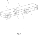
- Fig. 4 shows a further schematic and perspective detailed representation of the in Fig. 1 shown floor module 1. Only the cuboid adapter 9 is shown.
- the adapter component 9 is formed from two adapter parts 10 and 11 lying one on top of the other, the pipe bushings 8 being formed by both adapter parts 10 and 11 - here in each case half.
- Each adapter part 10 or 11 is provided with slots 38 on each pipe bushing 8. As a result, each adapter part 10 or 11 can better nestle against the pipe guided through the pipe bushing 8. If necessary, it can be refrained from preforming the pipe bushing 8 in addition to the slots, in particular if the adapter parts 10 and 11 consist of a correspondingly flexible and deformable foam.
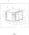
- Fig. 5 shows a schematic and perspective view of a further embodiment of a floor module 1 for holding a heat pump 18 of a household appliance 15 for drying laundry, this embodiment not being part of the claimed invention.
- the floor module 1 comprises a heat exchanger receiving area 19 for receiving heat exchangers 20 of the heat pump 18, of which in Fig. 5 only one heat exchanger 20 is shown, and a component receiving area 21 for at least partially receiving a compressor (not shown) and / or a throttle (not shown) of the heat pump 18.
- the base module 1 comprises a module housing 22 with a base-side receiving component 23 on which the heat exchanger receiving area 19 and the component receiving area 21 are formed, and a heat exchanger cover 24 which closes the heat exchanger receiving area 19 on the bottom side.
- the floor module 1 further comprises a partition wall 25 separating the heat exchanger receiving area 19 from the component receiving area 21, on which four pipe lead-throughs 26 for carrying out a respective pipe 27 of a refrigerant circuit Heat pump 18 are arranged.
- the pipe bushings 26 can be produced, for example, by a stamping process.
- the partition wall 25 is partially formed by a separately formed adapter component 28 having the pipe bushings 26.
- the adapter component 28 comprises a dimensionally stable frame component 29 made of a thermoplastic plastic and connected to the remaining partition 37 and a pipe lead-through component 30 encased in the frame component 29, the tube lead-through component 30 being made of a resilient plastic. Consequently, the adapter component 28 comprises a bushing section having the pipe bushings 26 made of a flexible plastic.
- the frame component 29 can be connected to the remaining partition 37 via at least one screw connection, not shown, or at least one snap connection, not shown, for which purpose four outward-facing fastening tabs 31 are arranged on the frame component 29.
- the compliant plastic can be a foam or an elastomer.
- Fig. 6 shows a schematic and perspective exploded view of the in Fig. 5 shown bottom module 1.
- both heat exchangers 20 and 32 of the heat pump 18 can be seen.
- a flange section 33 or 34 is arranged on the heat exchanger cover 24 and on the bottom receiving component 23, to which the adapter component 28 or its frame component 29 can be fastened.
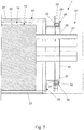
- Fig. 7 shows a schematic sectional view of the in Fig. 5 shown floor module 1. It can be seen that a flexible sealing element 35 made of an elastomer for sealing the heat exchanger receiving area 19 from the environment is arranged on the adapter component 28 or on the frame component 29 thereof. The sealing element 35 forming a sealing lip is partially received in a receptacle 36 on the frame component 29. Is the adapter component 28, as in Fig. 7 shown, attached to the flange sections 33 and 34, the sealing element 35 contacts the flange sections 33 and 34 for said sealing.
- Fig. 8 shows a schematic sectional view of the in Fig. 5 shown adapter component 28. In particular, the circumferential arrangement of the sealing element 35 can be seen.
- Fig. 9 shows a schematic and perspective view of the in Fig. 5 shown adapter component 28 before punching, through which the pipe bushings can be formed on the pipe bushing component 30.
- Fig. 10 shows a schematic and perspective view of the in Fig. 5 shown adapter component 28 after punching, whereby circular tube feedthroughs 26 have been formed on the stirring leadthrough component 30.
- Fig. 11 shows a further schematic and perspective representation of the in Fig. 5 shown adapter component 28 after punching, whereby 30-shaped pipe lead-throughs 26 have been formed on the stirring leadthrough component.
Landscapes
- Engineering & Computer Science (AREA)
- Textile Engineering (AREA)
- Detail Structures Of Washing Machines And Dryers (AREA)
- Drying Of Solid Materials (AREA)
- Heat-Exchange Devices With Radiators And Conduit Assemblies (AREA)
Claims (8)
- Module de sol (1) destiné à fixer une pompe de chaleur (18) d'un appareil ménager (15) destiné à sécher du linge, présentant :- au moins une zone de logement d'échangeur de chaleur (2, 19) pour le logement au moins partiel d'au moins un échangeur de chaleur (20, 32) de la pompe de chaleur (18),- au moins une zone de logement de composant (3, 21) pour le logement au moins partiel d'un condenseur et/ou d'un étrangleur de la pompe de chaleur (18), et- au moins une paroi de séparation (7, 25) séparant la zone de logement d'échangeur de chaleur (2, 19) au moins en partie de la zone de logement de composant (3, 21), sur laquelle paroi de séparation est disposé au moins un passage de tube (8, 26) pour le passage d'une conduite (27) d'un circuit de refroidissement de la pompe de chaleur (18),- la paroi de séparation (7, 25) étant formée au moins en partie par au moins un composant adaptateur (9, 28) réalisé de manière séparée, présentant le passage de tube (8, 26),- le composant adaptateur (9, 28) présentant une section de passage présentant le passage de tube (8, 26), constituée de matière plastique souple sous forme d'une mousse ou d'un élastomère ou d'une mousse de montage entourée par un film,caractérisé en ce que
le composant adaptateur (9, 28) est formé par deux pièces d'adaptateur (10, 11) posées l'une sur l'autre, le passage de tube (8, 26) étant formé par les deux pièces d'adaptateur (10, 11),- les pièces d'adaptateur (10, 11) étant munies de fentes (38) sur le passage de tube (8, 26). - Module de sol (1) selon la revendication 1, caractérisé en ce que sur le composant adaptateur (28), au moins un élément d'étanchéité (35) flexible destiné à étanchéifier la zone de logement d'échangeur de chaleur (19) est disposé vis-à-vis des environs.
- Module de sol (1) selon la revendication 1 ou 2, caractérisé par un boîtier de module (4, 22) comprenant un composant de logement (5, 23) côté sol, sur lequel sont réalisées la zone de logement d'échangeur de chaleur (2, 19) et la zone de logement de composant (3, 21), et comprenant un recouvrement (6, 24) d'échangeur de chaleur fermant la zone de logement d'échangeur de chaleur (2, 19) du côté détourné du sol, un premier élément de cadre (13) étant disposé sur une section de paroi, reliée au composant de logement (5), de la paroi de séparation (7) et un deuxième élément de cadre (14) étant disposé sur le recouvrement (6) d'échangeur de chaleur, les éléments de cadre (13, 14) formant un cadre pour le logement du composant adaptateur (9) par adhérence de forme.
- Module de sol (1) selon la revendication 1 ou 2, caractérisé en ce que le composant adaptateur (28) présente un élément de cadre (29) rigide raccordable au reste de la paroi de séparation (37) et un élément de passage de tube (30) encadré dans l'élément de cadre (29), l'élément de passage de tube (30) étant fabriqué dans la matière plastique souple.
- Module de sol (1) selon la revendication 4, caractérisé en ce que l'élément de cadre (29) est fabriqué dans une matière thermoplastique.
- Module de sol (1) selon la revendication 4 ou 5, caractérisé en ce que l'élément de cadre (29) est relié au reste de la paroi de séparation (37) par l'intermédiaire d'au moins une liaison à vis ou une liaison à encliquetage.
- Module de sol (1) selon l'une quelconque des revendications 1 à 6, caractérisé en ce que le passage de tube (8, 26) est fabriqué au moyen d'une opération d'estampage.
- Appareil ménager (15) destiné à sécher du linge, présentant au moins une pompe de chaleur (18), caractérisé par au moins un module de sol (1) selon l'une quelconque des revendications 1 à 7.
Priority Applications (1)
| Application Number | Priority Date | Filing Date | Title |
|---|---|---|---|
| PL17707521T PL3443157T3 (pl) | 2016-04-14 | 2017-02-24 | Moduł podstawy do urządzenia gospodarstwa domowego do suszenia prania i urządzenie gospodarstwa domowego |
Applications Claiming Priority (2)
| Application Number | Priority Date | Filing Date | Title |
|---|---|---|---|
| DE102016206229.8A DE102016206229A1 (de) | 2016-04-14 | 2016-04-14 | Bodenmodul für ein Haushaltsgerät zum Trocknen von Wäsche sowie Haushaltsgerät |
| PCT/EP2017/054267 WO2017178143A1 (fr) | 2016-04-14 | 2017-02-24 | Module au sol pour appareil ménager pour sécher le linge et appareil ménager |
Publications (2)
| Publication Number | Publication Date |
|---|---|
| EP3443157A1 EP3443157A1 (fr) | 2019-02-20 |
| EP3443157B1 true EP3443157B1 (fr) | 2020-01-29 |
Family
ID=58185516
Family Applications (1)
| Application Number | Title | Priority Date | Filing Date |
|---|---|---|---|
| EP17707521.5A Active EP3443157B1 (fr) | 2016-04-14 | 2017-02-24 | Module au sol pour appareil ménager pour sécher le linge et appareil ménager |
Country Status (5)
| Country | Link |
|---|---|
| EP (1) | EP3443157B1 (fr) |
| CN (1) | CN108884624B (fr) |
| DE (1) | DE102016206229A1 (fr) |
| PL (1) | PL3443157T3 (fr) |
| WO (1) | WO2017178143A1 (fr) |
Families Citing this family (2)
| Publication number | Priority date | Publication date | Assignee | Title |
|---|---|---|---|---|
| TR201721751A2 (tr) * | 2017-12-26 | 2019-07-22 | Arcelik As | Isi pompali ürünlerde farkli ti̇p eşanjör kullanilmasina olanak sağlayan bi̇r si̇stem |
| CN112095280B (zh) * | 2020-08-31 | 2024-10-29 | 天津海尔洗涤电器有限公司 | 滚筒洗衣机及其管路固定部件 |
Family Cites Families (11)
| Publication number | Priority date | Publication date | Assignee | Title |
|---|---|---|---|---|
| DE102008009782A1 (de) * | 2008-02-19 | 2009-08-27 | BSH Bosch und Siemens Hausgeräte GmbH | Hausgerät zum Trocknen eines feuchten Gutes mit einer Kühlanordnung und einer Heizanordnung |
| DE102008009784A1 (de) * | 2008-02-19 | 2009-08-27 | BSH Bosch und Siemens Hausgeräte GmbH | Hausgerät zum Trocknen eines feuchten Gutes mit einer Kühlanordnung und einer Heizanordnung |
| EP2423376B1 (fr) * | 2010-08-25 | 2013-04-24 | Electrolux Home Products Corporation N.V. | Machine de traitement du linge |
| EP2458072A1 (fr) * | 2010-11-29 | 2012-05-30 | Electrolux Home Products Corporation N.V. | Sèche-linge |
| PL2471994T3 (pl) * | 2011-01-04 | 2019-12-31 | Electrolux Home Products Corporation N.V. | Urządzenie do suszenia materiałów pranych |
| EP2527526B1 (fr) * | 2011-05-27 | 2014-07-23 | Electrolux Home Products Corporation N.V. | Sèche-linge à tambour rotatif |
| EP2708638A1 (fr) * | 2012-09-13 | 2014-03-19 | Electrolux Home Products Corporation N.V. | Sèche-linge à tambour rotatif |
| DE102013113506B4 (de) * | 2013-12-05 | 2018-12-20 | Miele & Cie. Kg | Haushaltsgeräte wie beispielsweise ein Wäschetrockner, ein Geschirrspüler oder ein Waschtrockner mit einer Wärmepumpeneinheit, sowie Verpackungsmaterial für einen Wärmetauscher einerWärmepumpeneinrichtung |
| DE102014102811A1 (de) * | 2014-03-04 | 2015-09-10 | Miele & Cie. Kg | Haushaltsgerät wie beispielsweise ein Wäschetrockner, ein Geschirrspüler oder ein Waschtrockner mit einer Wärmepumpeneinrichtung |
| DE102014216485A1 (de) | 2014-08-20 | 2016-02-25 | BSH Hausgeräte GmbH | Bodenmodul für ein Haushaltsgerät |
| EP2990519B1 (fr) * | 2014-08-29 | 2019-10-30 | Electrolux Appliances Aktiebolag | Sèche-linge |
-
2016
- 2016-04-14 DE DE102016206229.8A patent/DE102016206229A1/de not_active Withdrawn
-
2017
- 2017-02-24 WO PCT/EP2017/054267 patent/WO2017178143A1/fr not_active Ceased
- 2017-02-24 PL PL17707521T patent/PL3443157T3/pl unknown
- 2017-02-24 CN CN201780021960.8A patent/CN108884624B/zh active Active
- 2017-02-24 EP EP17707521.5A patent/EP3443157B1/fr active Active
Non-Patent Citations (1)
| Title |
|---|
| None * |
Also Published As
| Publication number | Publication date |
|---|---|
| DE102016206229A1 (de) | 2017-10-19 |
| PL3443157T3 (pl) | 2020-07-13 |
| WO2017178143A1 (fr) | 2017-10-19 |
| CN108884624A (zh) | 2018-11-23 |
| EP3443157A1 (fr) | 2019-02-20 |
| CN108884624B (zh) | 2020-11-10 |
Similar Documents
| Publication | Publication Date | Title |
|---|---|---|
| EP1931904B1 (fr) | Piece de liaison et de raccordement destinee a des tubes ondules | |
| EP3292604A1 (fr) | Ensemble comprenant une traversée murale pour plusieurs câbles ainsi que procédé de fabrication et kit | |
| EP3093172B1 (fr) | Systeme d'assemblage d'un echangeur thermique | |
| DE102009056043A1 (de) | Dichtungsanordnung für die Kraftfahrzeugstirnwand | |
| WO2020221537A1 (fr) | Ensemble de fixation ayant une action d'amortissement et raccordement de composant à l'ensemble de fixation | |
| EP3443157B1 (fr) | Module au sol pour appareil ménager pour sécher le linge et appareil ménager | |
| WO2012104013A1 (fr) | Boîtier d'antenne, doté en particulier d'un élément de retenue | |
| EP3529538A1 (fr) | Élément arqué pour système de ventilation | |
| DE102012014695B4 (de) | Wechselrichter mit mehreren Wanddurchführungen | |
| DE19828362B4 (de) | Lüfterhaube für eine Wärmeübertrageranordnung eines Kraftfahrzeugs | |
| DE102014113924A1 (de) | Fahrzeugklimaanlagenmoduldichtung und Baugruppe mit einer Fahrzeugklimaanlagenmoduldichtung | |
| EP3483996B1 (fr) | Dispositif pour un passe-câble | |
| DE2527132A1 (de) | Anschlussvorrichtung fuer einen heizkoerper | |
| DE102012218089A1 (de) | Wärmeübertrager und Halterungselement | |
| DE112013002850B4 (de) | Schwingungselementanbringstruktur | |
| DE102016209317B4 (de) | Elektrisches Antriebsmodul und Hybridsystem | |
| DE102010048510A1 (de) | Hydraulikzylinder | |
| DE102015105651B4 (de) | Dichtungselement für einen Lüftungskanal, Lüftungssystem mit Dichtung und Verfahren zur Herstellung eines Lüftungssystems | |
| DE102008016794B3 (de) | Rohreinheit aus wenigstens zwei miteinander verbundenen Rohrabschnitten | |
| WO2017182149A1 (fr) | Dispositif pneumatique à plusieurs soupapes ainsi que procédé de fabrication | |
| EP1970614B1 (fr) | Armature de tuyau souple pour un tuyau souple doté de plusieurs chambres | |
| EP4623253A1 (fr) | Système de raccordement pour composants pour le conditionnement thermique d'un bâtiment | |
| EP3034337B1 (fr) | Systeme de conduite d'air pour un vehicule automobile | |
| DE112008000643B4 (de) | System und Verfahren zum Erleichtern der fachgerechten Montage einer Abgasanlage | |
| DE102013216417A1 (de) | Dichtungsanordnung |
Legal Events
| Date | Code | Title | Description |
|---|---|---|---|
| STAA | Information on the status of an ep patent application or granted ep patent |
Free format text: STATUS: UNKNOWN |
|
| STAA | Information on the status of an ep patent application or granted ep patent |
Free format text: STATUS: THE INTERNATIONAL PUBLICATION HAS BEEN MADE |
|
| PUAI | Public reference made under article 153(3) epc to a published international application that has entered the european phase |
Free format text: ORIGINAL CODE: 0009012 |
|
| STAA | Information on the status of an ep patent application or granted ep patent |
Free format text: STATUS: REQUEST FOR EXAMINATION WAS MADE |
|
| 17P | Request for examination filed |
Effective date: 20181114 |
|
| AK | Designated contracting states |
Kind code of ref document: A1 Designated state(s): AL AT BE BG CH CY CZ DE DK EE ES FI FR GB GR HR HU IE IS IT LI LT LU LV MC MK MT NL NO PL PT RO RS SE SI SK SM TR |
|
| AX | Request for extension of the european patent |
Extension state: BA ME |
|
| RIN1 | Information on inventor provided before grant (corrected) |
Inventor name: EDIGER, RAINER Inventor name: SCHOLZE, TOBIAS Inventor name: HENTSCHEL, FELIX Inventor name: KOHLRUSCH, FRANK Inventor name: DREBANT, ALEXANDER Inventor name: WEGENER, DIRK Inventor name: BAURMANN, MARTIN Inventor name: KORTE, MARTIN Inventor name: SCHUBERT, MARTIN |
|
| DAV | Request for validation of the european patent (deleted) | ||
| DAX | Request for extension of the european patent (deleted) | ||
| GRAP | Despatch of communication of intention to grant a patent |
Free format text: ORIGINAL CODE: EPIDOSNIGR1 |
|
| STAA | Information on the status of an ep patent application or granted ep patent |
Free format text: STATUS: GRANT OF PATENT IS INTENDED |
|
| INTG | Intention to grant announced |
Effective date: 20190912 |
|
| GRAS | Grant fee paid |
Free format text: ORIGINAL CODE: EPIDOSNIGR3 |
|
| GRAA | (expected) grant |
Free format text: ORIGINAL CODE: 0009210 |
|
| STAA | Information on the status of an ep patent application or granted ep patent |
Free format text: STATUS: THE PATENT HAS BEEN GRANTED |
|
| AK | Designated contracting states |
Kind code of ref document: B1 Designated state(s): AL AT BE BG CH CY CZ DE DK EE ES FI FR GB GR HR HU IE IS IT LI LT LU LV MC MK MT NL NO PL PT RO RS SE SI SK SM TR |
|
| REG | Reference to a national code |
Ref country code: GB Ref legal event code: FG4D Free format text: NOT ENGLISH |
|
| REG | Reference to a national code |
Ref country code: CH Ref legal event code: EP |
|
| REG | Reference to a national code |
Ref country code: AT Ref legal event code: REF Ref document number: 1228565 Country of ref document: AT Kind code of ref document: T Effective date: 20200215 |
|
| REG | Reference to a national code |
Ref country code: IE Ref legal event code: FG4D Free format text: LANGUAGE OF EP DOCUMENT: GERMAN |
|
| REG | Reference to a national code |
Ref country code: DE Ref legal event code: R096 Ref document number: 502017003630 Country of ref document: DE |
|
| REG | Reference to a national code |
Ref country code: NL Ref legal event code: MP Effective date: 20200129 |
|
| PG25 | Lapsed in a contracting state [announced via postgrant information from national office to epo] |
Ref country code: PT Free format text: LAPSE BECAUSE OF FAILURE TO SUBMIT A TRANSLATION OF THE DESCRIPTION OR TO PAY THE FEE WITHIN THE PRESCRIBED TIME-LIMIT Effective date: 20200621 Ref country code: FI Free format text: LAPSE BECAUSE OF FAILURE TO SUBMIT A TRANSLATION OF THE DESCRIPTION OR TO PAY THE FEE WITHIN THE PRESCRIBED TIME-LIMIT Effective date: 20200129 Ref country code: NO Free format text: LAPSE BECAUSE OF FAILURE TO SUBMIT A TRANSLATION OF THE DESCRIPTION OR TO PAY THE FEE WITHIN THE PRESCRIBED TIME-LIMIT Effective date: 20200429 Ref country code: RS Free format text: LAPSE BECAUSE OF FAILURE TO SUBMIT A TRANSLATION OF THE DESCRIPTION OR TO PAY THE FEE WITHIN THE PRESCRIBED TIME-LIMIT Effective date: 20200129 |
|
| REG | Reference to a national code |
Ref country code: LT Ref legal event code: MG4D |
|
| PG25 | Lapsed in a contracting state [announced via postgrant information from national office to epo] |
Ref country code: IS Free format text: LAPSE BECAUSE OF FAILURE TO SUBMIT A TRANSLATION OF THE DESCRIPTION OR TO PAY THE FEE WITHIN THE PRESCRIBED TIME-LIMIT Effective date: 20200529 Ref country code: HR Free format text: LAPSE BECAUSE OF FAILURE TO SUBMIT A TRANSLATION OF THE DESCRIPTION OR TO PAY THE FEE WITHIN THE PRESCRIBED TIME-LIMIT Effective date: 20200129 Ref country code: SE Free format text: LAPSE BECAUSE OF FAILURE TO SUBMIT A TRANSLATION OF THE DESCRIPTION OR TO PAY THE FEE WITHIN THE PRESCRIBED TIME-LIMIT Effective date: 20200129 Ref country code: LV Free format text: LAPSE BECAUSE OF FAILURE TO SUBMIT A TRANSLATION OF THE DESCRIPTION OR TO PAY THE FEE WITHIN THE PRESCRIBED TIME-LIMIT Effective date: 20200129 Ref country code: BG Free format text: LAPSE BECAUSE OF FAILURE TO SUBMIT A TRANSLATION OF THE DESCRIPTION OR TO PAY THE FEE WITHIN THE PRESCRIBED TIME-LIMIT Effective date: 20200429 Ref country code: GR Free format text: LAPSE BECAUSE OF FAILURE TO SUBMIT A TRANSLATION OF THE DESCRIPTION OR TO PAY THE FEE WITHIN THE PRESCRIBED TIME-LIMIT Effective date: 20200430 |
|
| PG25 | Lapsed in a contracting state [announced via postgrant information from national office to epo] |
Ref country code: NL Free format text: LAPSE BECAUSE OF FAILURE TO SUBMIT A TRANSLATION OF THE DESCRIPTION OR TO PAY THE FEE WITHIN THE PRESCRIBED TIME-LIMIT Effective date: 20200129 |
|
| REG | Reference to a national code |
Ref country code: CH Ref legal event code: PL |
|
| REG | Reference to a national code |
Ref country code: BE Ref legal event code: MM Effective date: 20200229 |
|
| PG25 | Lapsed in a contracting state [announced via postgrant information from national office to epo] |
Ref country code: DK Free format text: LAPSE BECAUSE OF FAILURE TO SUBMIT A TRANSLATION OF THE DESCRIPTION OR TO PAY THE FEE WITHIN THE PRESCRIBED TIME-LIMIT Effective date: 20200129 Ref country code: LT Free format text: LAPSE BECAUSE OF FAILURE TO SUBMIT A TRANSLATION OF THE DESCRIPTION OR TO PAY THE FEE WITHIN THE PRESCRIBED TIME-LIMIT Effective date: 20200129 Ref country code: SM Free format text: LAPSE BECAUSE OF FAILURE TO SUBMIT A TRANSLATION OF THE DESCRIPTION OR TO PAY THE FEE WITHIN THE PRESCRIBED TIME-LIMIT Effective date: 20200129 Ref country code: EE Free format text: LAPSE BECAUSE OF FAILURE TO SUBMIT A TRANSLATION OF THE DESCRIPTION OR TO PAY THE FEE WITHIN THE PRESCRIBED TIME-LIMIT Effective date: 20200129 Ref country code: ES Free format text: LAPSE BECAUSE OF FAILURE TO SUBMIT A TRANSLATION OF THE DESCRIPTION OR TO PAY THE FEE WITHIN THE PRESCRIBED TIME-LIMIT Effective date: 20200129 Ref country code: RO Free format text: LAPSE BECAUSE OF FAILURE TO SUBMIT A TRANSLATION OF THE DESCRIPTION OR TO PAY THE FEE WITHIN THE PRESCRIBED TIME-LIMIT Effective date: 20200129 Ref country code: CZ Free format text: LAPSE BECAUSE OF FAILURE TO SUBMIT A TRANSLATION OF THE DESCRIPTION OR TO PAY THE FEE WITHIN THE PRESCRIBED TIME-LIMIT Effective date: 20200129 Ref country code: LU Free format text: LAPSE BECAUSE OF NON-PAYMENT OF DUE FEES Effective date: 20200224 Ref country code: MC Free format text: LAPSE BECAUSE OF FAILURE TO SUBMIT A TRANSLATION OF THE DESCRIPTION OR TO PAY THE FEE WITHIN THE PRESCRIBED TIME-LIMIT Effective date: 20200129 Ref country code: SK Free format text: LAPSE BECAUSE OF FAILURE TO SUBMIT A TRANSLATION OF THE DESCRIPTION OR TO PAY THE FEE WITHIN THE PRESCRIBED TIME-LIMIT Effective date: 20200129 |
|
| REG | Reference to a national code |
Ref country code: DE Ref legal event code: R097 Ref document number: 502017003630 Country of ref document: DE |
|
| PG25 | Lapsed in a contracting state [announced via postgrant information from national office to epo] |
Ref country code: LI Free format text: LAPSE BECAUSE OF NON-PAYMENT OF DUE FEES Effective date: 20200229 Ref country code: CH Free format text: LAPSE BECAUSE OF NON-PAYMENT OF DUE FEES Effective date: 20200229 |
|
| PLBE | No opposition filed within time limit |
Free format text: ORIGINAL CODE: 0009261 |
|
| STAA | Information on the status of an ep patent application or granted ep patent |
Free format text: STATUS: NO OPPOSITION FILED WITHIN TIME LIMIT |
|
| 26N | No opposition filed |
Effective date: 20201030 |
|
| PG25 | Lapsed in a contracting state [announced via postgrant information from national office to epo] |
Ref country code: IT Free format text: LAPSE BECAUSE OF FAILURE TO SUBMIT A TRANSLATION OF THE DESCRIPTION OR TO PAY THE FEE WITHIN THE PRESCRIBED TIME-LIMIT Effective date: 20200129 Ref country code: FR Free format text: LAPSE BECAUSE OF NON-PAYMENT OF DUE FEES Effective date: 20200329 Ref country code: IE Free format text: LAPSE BECAUSE OF NON-PAYMENT OF DUE FEES Effective date: 20200224 |
|
| PG25 | Lapsed in a contracting state [announced via postgrant information from national office to epo] |
Ref country code: BE Free format text: LAPSE BECAUSE OF NON-PAYMENT OF DUE FEES Effective date: 20200229 Ref country code: SI Free format text: LAPSE BECAUSE OF FAILURE TO SUBMIT A TRANSLATION OF THE DESCRIPTION OR TO PAY THE FEE WITHIN THE PRESCRIBED TIME-LIMIT Effective date: 20200129 |
|
| GBPC | Gb: european patent ceased through non-payment of renewal fee |
Effective date: 20210224 |
|
| PG25 | Lapsed in a contracting state [announced via postgrant information from national office to epo] |
Ref country code: GB Free format text: LAPSE BECAUSE OF NON-PAYMENT OF DUE FEES Effective date: 20210224 |
|
| PG25 | Lapsed in a contracting state [announced via postgrant information from national office to epo] |
Ref country code: TR Free format text: LAPSE BECAUSE OF FAILURE TO SUBMIT A TRANSLATION OF THE DESCRIPTION OR TO PAY THE FEE WITHIN THE PRESCRIBED TIME-LIMIT Effective date: 20200129 Ref country code: MT Free format text: LAPSE BECAUSE OF FAILURE TO SUBMIT A TRANSLATION OF THE DESCRIPTION OR TO PAY THE FEE WITHIN THE PRESCRIBED TIME-LIMIT Effective date: 20200129 Ref country code: CY Free format text: LAPSE BECAUSE OF FAILURE TO SUBMIT A TRANSLATION OF THE DESCRIPTION OR TO PAY THE FEE WITHIN THE PRESCRIBED TIME-LIMIT Effective date: 20200129 |
|
| PG25 | Lapsed in a contracting state [announced via postgrant information from national office to epo] |
Ref country code: MK Free format text: LAPSE BECAUSE OF FAILURE TO SUBMIT A TRANSLATION OF THE DESCRIPTION OR TO PAY THE FEE WITHIN THE PRESCRIBED TIME-LIMIT Effective date: 20200129 Ref country code: AL Free format text: LAPSE BECAUSE OF FAILURE TO SUBMIT A TRANSLATION OF THE DESCRIPTION OR TO PAY THE FEE WITHIN THE PRESCRIBED TIME-LIMIT Effective date: 20200129 |
|
| REG | Reference to a national code |
Ref country code: DE Ref legal event code: R084 Ref document number: 502017003630 Country of ref document: DE |
|
| REG | Reference to a national code |
Ref country code: AT Ref legal event code: MM01 Ref document number: 1228565 Country of ref document: AT Kind code of ref document: T Effective date: 20220224 |
|
| PG25 | Lapsed in a contracting state [announced via postgrant information from national office to epo] |
Ref country code: AT Free format text: LAPSE BECAUSE OF NON-PAYMENT OF DUE FEES Effective date: 20220224 |
|
| PGFP | Annual fee paid to national office [announced via postgrant information from national office to epo] |
Ref country code: PL Payment date: 20250213 Year of fee payment: 9 |
|
| PGFP | Annual fee paid to national office [announced via postgrant information from national office to epo] |
Ref country code: DE Payment date: 20260228 Year of fee payment: 10 |