EP3443234B1 - Beschlag zum lösbaren verbinden zweier möbelteile - Google Patents
Beschlag zum lösbaren verbinden zweier möbelteile Download PDFInfo
- Publication number
- EP3443234B1 EP3443234B1 EP17710167.2A EP17710167A EP3443234B1 EP 3443234 B1 EP3443234 B1 EP 3443234B1 EP 17710167 A EP17710167 A EP 17710167A EP 3443234 B1 EP3443234 B1 EP 3443234B1
- Authority
- EP
- European Patent Office
- Prior art keywords
- fitting
- latching
- latching tongue
- tongue
- fitting part
- Prior art date
- Legal status (The legal status is an assumption and is not a legal conclusion. Google has not performed a legal analysis and makes no representation as to the accuracy of the status listed.)
- Active
Links
Images


Classifications
-
- F—MECHANICAL ENGINEERING; LIGHTING; HEATING; WEAPONS; BLASTING
- F16—ENGINEERING ELEMENTS AND UNITS; GENERAL MEASURES FOR PRODUCING AND MAINTAINING EFFECTIVE FUNCTIONING OF MACHINES OR INSTALLATIONS; THERMAL INSULATION IN GENERAL
- F16B—DEVICES FOR FASTENING OR SECURING CONSTRUCTIONAL ELEMENTS OR MACHINE PARTS TOGETHER, e.g. NAILS, BOLTS, CIRCLIPS, CLAMPS, CLIPS OR WEDGES; JOINTS OR JOINTING
- F16B12/00—Jointing of furniture or the like, e.g. hidden from exterior
- F16B12/10—Jointing of furniture or the like, e.g. hidden from exterior using pegs, bolts, tenons, clamps, clips, or the like
- F16B12/12—Jointing of furniture or the like, e.g. hidden from exterior using pegs, bolts, tenons, clamps, clips, or the like for non-metal furniture parts, e.g. made of wood, of plastics
- F16B12/26—Jointing of furniture or the like, e.g. hidden from exterior using pegs, bolts, tenons, clamps, clips, or the like for non-metal furniture parts, e.g. made of wood, of plastics using snap-action elements
-
- A—HUMAN NECESSITIES
- A47—FURNITURE; DOMESTIC ARTICLES OR APPLIANCES; COFFEE MILLS; SPICE MILLS; SUCTION CLEANERS IN GENERAL
- A47B—TABLES; DESKS; OFFICE FURNITURE; CABINETS; DRAWERS; GENERAL DETAILS OF FURNITURE
- A47B96/00—Details of cabinets, racks or shelf units not covered by a single one of groups A47B43/00 - A47B95/00; General details of furniture
- A47B96/06—Brackets or similar supporting means for cabinets, racks or shelves
Definitions
- the invention relates to a fitting for releasably connecting two furniture parts, consisting of a first fitting part which can be fastened to a first furniture part and a second fitting part which can be fastened to a second furniture part, at least one rigid latching cam being arranged on the second fitting part, which is in the inserted state of the fitting parts is engaged by a locking lug which is attached to a deflectable locking tongue of the first fitting part, the locking tongue being movable out of its locking position engaging behind the locking cams into a release position which no longer engages behind the locking cams and can be fixed in this release position on the second fitting part is and this fixation can be canceled by separating the fitting parts, and wherein the latching tongue in turn has at least one latching spring.
- the invention also relates to an arrangement with two furniture parts which are connected to one another by such a fitting.
- Such a two-part fitting is for example by WO 98/22721 A1 become known in which a releasable connection between two housing parts is described.
- a two-piece fitting for releasably connecting two pieces of furniture is from the EP 0 681 109 A2 known in Fig. 7 shows a second fitting part with two molded, rigid locking cams. Behind these locking cams, the resilient locking tongue of the first fitting part can be locked in its release position, and when the two fitting parts are separated, the resilient locking tongue will snap back into its ready-to-connect basic position as soon as it has no contact with the locking cams. A renewed assembly of the two fitting parts will in turn cause the locking cams to engage behind through the corresponding locking lugs of the resilient locking tongue of the first fitting part.
- the resilient latching tongue must be designed to be elastically deformable to such an extent that it can be moved past the locking cams into its release position.
- the at least one latching spring on the counterbearing is deflected transversely to the deflection plane of the latching tongue and is thereby preloaded.
- the latching spring then snaps back and engages behind the counter bearing, as a result of which the deflected latching tongue is locked on the carrier part.
- the latching tongue preferably has such a latching spring on both sides, the free spring end of which can be deflected transversely to the deflection plane of the latching tongue when the fitting parts are inserted into one another by a counter bearing of the second fitting part.
- the second fitting part therefore preferably has a support base with an access opening through which a tool for deflecting the latching tongue can be inserted.
- This access opening can be a round hole or a slot or cross-slot opening. If the locking tongue extends into the access opening or even protrudes from it when the fitting parts are inserted into one another, the locking tongue can also be deflected into the release position with a finger.
- the invention also relates to an arrangement comprising a first furniture part with a bottom-side, open-edge hole, a second furniture part with a hole and a fitting designed as above, the first fitting part in the hole in the first furniture part and the second fitting part in the hole in the second furniture part are used and the two fitting parts are locked together in the inserted state by the latching tongue.
- the two furniture parts are preferably formed from wood or from a wood fiber material.
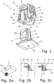
- the in Fig. 1 Fitting 1 shown serves for releasably connecting two furniture parts 2, 3 ( Fig. 2 ) and consists of a first fitting part 4 which can be fastened to the first furniture part 2 and a second fitting part 5 which can be fastened to the second furniture part 3.
- the fitting 1 serves as a shelf connector for fastening a shelf 2 to a body wall 3.
- the shelf 2 and the Body wall 3 are, for example, wood fiber boards.
- the first fitting part is designed as a one-piece drilling pot 4 with a pot base 6, with a pot opening 7 on the end face and with a longitudinal slot 8 provided in the peripheral wall, which is open towards the pot opening 7 and extends as far as the pot bottom 6.
- two pot wings 9 are cut free in the peripheral wall, which are connected to the peripheral wall only on their side facing the pot bottom 6 and are exposed to the outside beyond the peripheral wall.
- a ribbing in the form of a plurality of circumferential ribs 10 arranged axially one behind the other is integrally formed on the pot wings 9.
- a plurality of radially outwardly projecting edge sections 11 are provided at the pot opening 7 for depth limitation.
- the drilling pot 4 is made of plastic, for example.
- the second fitting part is designed as a one-piece support part 5, which has a support base 12 and a fastening leg 13 with a hole 14 which rises above the support base 12.
- the carrier part 5 is made of die-cast zinc, for example.
- the drilling-in pot 4 is pressed by hand to the depth limit into an underside, open-edge bore 15 of the tray 2. Due to the pot wings 9 on display, the drilling pot 4 automatically holds after being pressed in, but a twist-in pot 4 inserted into the bore 15 can still be aligned by hand.
- the carrier part 5 is fastened to the body wall 3 by means of a screw 16 which passes through the hole 14 and is screwed into a bore 17 in the body wall 3.
- the carrier part 5 can also be attached to the body wall 3 by means of a separate plug pin which passes through the hole 14 and is inserted into the bore 17, or by means of a plug pin which is formed on the carrier part 5 instead of the screw hole 14 and which is inserted into the bore 17 is to be attached.
- the molded pin can have wedge noses on its top.
- the tray 2 is suspended with its boring pot 4 from above onto the carrier part 5 fastened to the body wall 3, the boring pot 4 with its longitudinal slot 8 being plugged onto the fastening leg 13 of the carrier part 5.
- Inclined guide surfaces 18, 19 on the drilling-in pot 4 and on the fastening leg 13 have the effect during hanging that the drilling-in pot 4 is pulled in the direction of the body wall 3 and the tray 2 bears against the body wall 3 without gaps.
- plug end position is reached when the drilling pot 4 is seated on the support base 12. In this plug end position, on the one hand, as will be described in more detail below, the drilling-in pot 4 is locked (clipped) on the carrier part 5 against its plugging direction.
- the two pot wings 9 of the drill-in pot 4 are spread outwards by the fastening leg 13 and thereby the peripheral ribs 10 are pressed into the wall of the bore 15, that is to say into the wood material of the tray 2, so that the drill-in pot 4 is firmly anchored in the bore 15 .
- FIG. 3a-3c the locking of the drilling pot 4 on the carrier part 5 is shown in detail.
- a deflectable latching tongue 20 is attached in the drilling-in pot 4 and has a latching lug 21 with a bevel 22 on its free end directed towards the pot opening 7.
- a rigid locking cam 23 is arranged on the carrier part 5 and cooperates with the locking lug 21.
- a tool in the form of a thin pin 25 (diameter approx. 1.2 mm) is pushed up through a small round access opening 24 in the support base 12, which runs against the run-up bevel 22 of the locking lug 21 and thereby the locking tongue 20 from the locking position ( Fig. 3c ) deflects into a release position no longer engaging behind the locking cams 23 ( Fig. 4a ).
- the latching tongue 20 remains fixed even after removing the pin 25 ( Fig. 4b ) until the latching tongue 20 returns to its connection-ready basic position when the two fitting parts 4, 5 are separated ( Fig. 3a , 4c ) returns.
- the locking tongue 20 As in Fig. 1 and in detail in Fig. 5a is shown, on both sides of their locking lug 21, a locking spring 26 and the support part 5 on two above the support base 12 upright bearing 27 .
- the latching springs 26 on the counter bearings 27 are deflected transversely to the deflection plane 28 of the latching tongue 20 in the direction 29 towards the latching nose 21, that is to say towards one another, and thereby in opposite directions Biased towards ( Fig. 5b ) .
- the end faces 30, 31 of the detent springs 26 and the counterbearing 27 which meet when the fitting parts 4, 5 are inserted into one another run correspondingly obliquely to the plug-in direction in order to deflect the detent springs 26 in the direction of one another.
- the counter bearings 27 extend from the locking position to before the release position of the locking tongue 20, so that the locking springs 26 on the counter bearings 27 remain deflected and preloaded.
- the latching springs 26 then snap back, that is to say in the direction away from one another, and engage behind the counter bearings 27 ( Fig. 5c ), whereby the deflected latching tongue 20 is latched and prestressed on the carrier part 5 in the release position ( Fig.
- the latching tongue 20 is fixed until it no longer has any contact with the counter bearings 27 when the two fitting parts 4, 5 are separated and then returns to its basic position ready for connection ( Fig. 3a , 4c ) snaps back.
- the two side detent springs 26 shown alternatively only a single detent spring can be present.
- the access opening 24 in the support base 12 is designed as a slot or cross-slot opening in order to deflect the latching tongue 20 from the locking position into the shown release position with the aid of the tip of a screwdriver 25 inserted therein.
- Fig. 1 differs from in Fig. 7 Fitting 1 not shown according to the invention merely by a different fixation of the locking tongue 20 in the release position.
- Fig. 8a, 8b is shown, the outermost end of the latching tongue 20 is formed in the rear area facing away from the latching lug 21 as a latching head 32 with two outer sides 33 tapering towards the rear.
- the carrier part 5 has a slot 34 which is open at the top in its support base 12. While the locking head 32 in the in Fig. 8a Is shown locking position of the locking tongue 20 is spaced from the slot 34, it is in the in Fig.
- the latching head 32 can also be present at the rear region of the latching spring at another location; in particular, the entire rear side of the detent spring 20 can also have a detent cross section that tapers toward the rear.
- the access opening 24 in the support base 12 of the support part 5 is made so large that when the fitting parts 4, 5 are inserted into one another, the latching tongue 20 can be deflected with the finger from the locking position into the release position.
- the latching tongue 20 can be extended into the access opening 24 or protrude from the access opening 24.
Landscapes
- Engineering & Computer Science (AREA)
- General Engineering & Computer Science (AREA)
- Mechanical Engineering (AREA)
- Furniture Connections (AREA)
- Connection Of Plates (AREA)
- Clamps And Clips (AREA)
Priority Applications (2)
| Application Number | Priority Date | Filing Date | Title |
|---|---|---|---|
| PL17710167T PL3443234T3 (pl) | 2016-04-11 | 2017-03-07 | Okucie do rozłączalnego połączenia dwóch części mebla |
| SI201730325T SI3443234T1 (sl) | 2016-04-11 | 2017-03-07 | Fiting za razstavljivo povezavo dveh delov pohištva |
Applications Claiming Priority (2)
| Application Number | Priority Date | Filing Date | Title |
|---|---|---|---|
| DE202016101880.3U DE202016101880U1 (de) | 2016-04-11 | 2016-04-11 | Beschlag zum lösbaren Verbinden zweier Möbelteile |
| PCT/EP2017/055271 WO2017178152A1 (de) | 2016-04-11 | 2017-03-07 | Beschlag zum lösbaren verbinden zweier möbelteile |
Publications (2)
| Publication Number | Publication Date |
|---|---|
| EP3443234A1 EP3443234A1 (de) | 2019-02-20 |
| EP3443234B1 true EP3443234B1 (de) | 2020-04-29 |
Family
ID=55968220
Family Applications (1)
| Application Number | Title | Priority Date | Filing Date |
|---|---|---|---|
| EP17710167.2A Active EP3443234B1 (de) | 2016-04-11 | 2017-03-07 | Beschlag zum lösbaren verbinden zweier möbelteile |
Country Status (19)
| Country | Link |
|---|---|
| US (1) | US11085476B2 (pl) |
| EP (1) | EP3443234B1 (pl) |
| JP (1) | JP6732939B2 (pl) |
| KR (1) | KR102127065B1 (pl) |
| CN (1) | CN109642599B (pl) |
| AU (1) | AU2017249576B2 (pl) |
| BR (1) | BR112018070922A2 (pl) |
| CA (1) | CA3020627C (pl) |
| DE (1) | DE202016101880U1 (pl) |
| DK (1) | DK3443234T3 (pl) |
| ES (1) | ES2792084T3 (pl) |
| LT (1) | LT3443234T (pl) |
| MX (1) | MX2018012405A (pl) |
| MY (1) | MY196002A (pl) |
| PL (1) | PL3443234T3 (pl) |
| PT (1) | PT3443234T (pl) |
| RU (1) | RU2712343C1 (pl) |
| SI (1) | SI3443234T1 (pl) |
| WO (1) | WO2017178152A1 (pl) |
Families Citing this family (13)
| Publication number | Priority date | Publication date | Assignee | Title |
|---|---|---|---|---|
| EP3589846B1 (en) * | 2017-02-28 | 2022-06-15 | 3M Innovative Properties Company | Attachment device and related methods |
| DE202017006630U1 (de) * | 2017-12-27 | 2019-04-01 | Rehau Ag + Co | System zum Verbinden eines ersten Bauteils mit einem zweiten Bauteil |
| IT201800020011A1 (it) * | 2018-12-18 | 2020-06-18 | Bortoluzzi Sistemi Spa | sistema e metodo di bloccaggio per ripiani |
| IT201900009219A1 (it) * | 2019-06-17 | 2020-12-17 | Ferramenta Livenza Soc A Responsabilita Limitata | Elemento di supporto per ripiani di mobili |
| DE202019105741U1 (de) * | 2019-10-17 | 2019-10-31 | Häfele GmbH & Co KG | Möbel mit einem verdrehbaren, keilförmigen Bett |
| CN110762432B (zh) * | 2019-11-12 | 2021-08-20 | 南通市莱特电气科技发展有限公司 | 一种方便维修的隧道灯组件 |
| IT202000002677A1 (it) * | 2020-02-11 | 2021-08-11 | Bortoluzzi Sistemi Spa | “sistema di bloccaggio per ripiani di mobili” |
| KR102426335B1 (ko) * | 2020-11-05 | 2022-07-27 | 조정규 | 가구용 선반 받침구 및 이를 포함하는 가구 |
| CN113397301B (zh) * | 2021-06-28 | 2023-01-06 | 浙江捷昌线性驱动科技股份有限公司 | 一种速装桌架及桌子 |
| CN217539244U (zh) * | 2022-05-18 | 2022-10-04 | 广东精诺五金实业有限公司 | 一种第一连接件、连接组件及连接系统 |
| WO2023221967A1 (zh) * | 2022-05-18 | 2023-11-23 | 广东精诺五金实业有限公司 | 一种第一连接件、连接组件及连接系统 |
| CN117297279B (zh) * | 2023-09-19 | 2025-12-26 | 广东皮阿诺科学艺术家居股份有限公司 | 活动层板托 |
| CN223806398U (zh) * | 2024-04-23 | 2026-01-16 | 精诺科技研究(广东)有限公司 | 一种连接件、连接组件及连接系统 |
Family Cites Families (27)
| Publication number | Priority date | Publication date | Assignee | Title |
|---|---|---|---|---|
| US3545712A (en) * | 1968-09-26 | 1970-12-08 | Keystone Consolidated Ind Inc | Assembly bracket |
| US3675955A (en) * | 1970-03-23 | 1972-07-11 | Regis Mfg Co | Cabinet bracket |
| US4022352A (en) * | 1976-04-26 | 1977-05-10 | Pehr Harold T | Container cover and safety closure |
| US4127221A (en) * | 1978-03-20 | 1978-11-28 | Sterling Drug Inc. | Childproof device for containing and dispensing fluids |
| US4148454A (en) * | 1978-05-22 | 1979-04-10 | Keystone Consolidated Industries, Inc. | Bracket assembly |
| JPS56103236A (en) * | 1980-01-21 | 1981-08-18 | Teijin Ltd | Polyester composition |
| GB2088013A (en) * | 1980-11-18 | 1982-06-03 | Fletcher Frank | Fastening Means |
| DE3047642A1 (de) * | 1980-12-17 | 1982-10-28 | Arturo Salice S.p.A., 22060 Novedrate, Como | Verbindungsbeschlag |
| US4813808A (en) * | 1983-08-19 | 1989-03-21 | Gkn Automotive Components Inc. | Axial retaining member and method for interconnecting male and female splined members |
| CA1233311A (en) * | 1984-12-07 | 1988-03-01 | Robert M. St. Louis | Retainer clip |
| US5013073A (en) * | 1988-02-26 | 1991-05-07 | Pehr Harold T | Automatic reset window latch |
| JPH0650523U (ja) * | 1992-12-22 | 1994-07-12 | 吉田工業株式会社 | 袋物・鞄などの蓋の係止具 |
| DE9407537U1 (de) | 1994-05-06 | 1994-08-04 | Paul Hettich Gmbh & Co., 32278 Kirchlengern | Beschlag zum lösbaren Verbinden zweier Möbelteile |
| DE4419371C2 (de) * | 1994-06-03 | 1996-03-28 | Kautex Maschinenbau Gmbh | Verbindungsanordnung |
| JP3471430B2 (ja) * | 1994-07-18 | 2003-12-02 | 株式会社モルテン | クリップ |
| US5533237A (en) * | 1994-09-12 | 1996-07-09 | Emhart, Inc. | Grommet fastener assembly for automobiles |
| TW353263B (en) * | 1996-11-21 | 1999-02-21 | Koninkl Philips Electronics Nv | Detachable connection between two housing sections |
| ITBO20000288A1 (it) * | 2000-05-16 | 2001-11-16 | Gianfranco Destro | Giunto per il collegamento rapido e reversibile di due parti di un mobile poste tra loro a squadro . |
| JP4657419B2 (ja) * | 2000-05-22 | 2011-03-23 | 株式会社ニフコ | クリップ |
| DE10142508A1 (de) * | 2001-08-30 | 2003-03-27 | Bsh Bosch Siemens Hausgeraete | Rastvorrichtung und mit dieser ausgestattete Küchenmaschine |
| DE20302694U1 (de) * | 2003-02-19 | 2003-06-12 | Häfele GmbH & Co., 72202 Nagold | Beschlag |
| ITPN20030037U1 (it) * | 2003-11-14 | 2005-05-15 | Livenza Ferramenta Srl | Dispositivo reggi-piano perfezionato |
| EP1593862A1 (en) * | 2004-05-06 | 2005-11-09 | Euromid S.r.l. | Shelf adjustment device for intermediate shelves and bases of furniture |
| DE102007042484B3 (de) * | 2007-09-06 | 2009-01-08 | A. Raymond Et Cie | Vorrichtung zum Befestigen eines Anbauteiles an einem Trägerteil |
| US8045337B2 (en) * | 2008-04-03 | 2011-10-25 | Delphi Technologies, Inc. | Lock for a housing |
| JP5281534B2 (ja) * | 2009-10-05 | 2013-09-04 | ホシデン株式会社 | 端子ボックス |
| DE202012002741U1 (de) * | 2012-03-19 | 2012-04-25 | Siegenia-Aubi Kg | Beschlag für einen zumindest annähernd parallel abstellbaren und in dieser Parallelabstelllage horizontal verschiebbaren Flügel von Fenstern oder Türen |
-
2016
- 2016-04-11 DE DE202016101880.3U patent/DE202016101880U1/de not_active Expired - Lifetime
-
2017
- 2017-03-07 JP JP2018553194A patent/JP6732939B2/ja not_active Expired - Fee Related
- 2017-03-07 AU AU2017249576A patent/AU2017249576B2/en not_active Ceased
- 2017-03-07 PL PL17710167T patent/PL3443234T3/pl unknown
- 2017-03-07 LT LTEP17710167.2T patent/LT3443234T/lt unknown
- 2017-03-07 DK DK17710167.2T patent/DK3443234T3/da active
- 2017-03-07 MX MX2018012405A patent/MX2018012405A/es unknown
- 2017-03-07 BR BR112018070922A patent/BR112018070922A2/pt active Search and Examination
- 2017-03-07 CA CA3020627A patent/CA3020627C/en active Active
- 2017-03-07 KR KR1020187032212A patent/KR102127065B1/ko not_active Expired - Fee Related
- 2017-03-07 CN CN201780031974.8A patent/CN109642599B/zh not_active Expired - Fee Related
- 2017-03-07 PT PT177101672T patent/PT3443234T/pt unknown
- 2017-03-07 RU RU2018139310A patent/RU2712343C1/ru active
- 2017-03-07 MY MYPI2018703733A patent/MY196002A/en unknown
- 2017-03-07 ES ES17710167T patent/ES2792084T3/es active Active
- 2017-03-07 WO PCT/EP2017/055271 patent/WO2017178152A1/de not_active Ceased
- 2017-03-07 EP EP17710167.2A patent/EP3443234B1/de active Active
- 2017-03-07 SI SI201730325T patent/SI3443234T1/sl unknown
-
2018
- 2018-10-10 US US16/156,455 patent/US11085476B2/en active Active
Non-Patent Citations (1)
| Title |
|---|
| None * |
Also Published As
| Publication number | Publication date |
|---|---|
| RU2712343C1 (ru) | 2020-01-28 |
| PT3443234T (pt) | 2020-07-07 |
| CA3020627A1 (en) | 2017-10-19 |
| MX2018012405A (es) | 2019-02-21 |
| DE202016101880U1 (de) | 2016-04-27 |
| KR20190004712A (ko) | 2019-01-14 |
| PL3443234T3 (pl) | 2020-11-02 |
| US11085476B2 (en) | 2021-08-10 |
| LT3443234T (lt) | 2020-06-25 |
| SI3443234T1 (sl) | 2020-11-30 |
| AU2017249576B2 (en) | 2019-05-30 |
| EP3443234A1 (de) | 2019-02-20 |
| JP2019516044A (ja) | 2019-06-13 |
| CN109642599A (zh) | 2019-04-16 |
| WO2017178152A1 (de) | 2017-10-19 |
| JP6732939B2 (ja) | 2020-07-29 |
| CN109642599B (zh) | 2020-10-30 |
| AU2017249576A1 (en) | 2018-11-29 |
| CA3020627C (en) | 2020-04-28 |
| ES2792084T3 (es) | 2020-11-10 |
| KR102127065B1 (ko) | 2020-06-25 |
| US20190040892A1 (en) | 2019-02-07 |
| MY196002A (en) | 2023-02-27 |
| DK3443234T3 (da) | 2020-06-15 |
| BR112018070922A2 (pt) | 2019-01-29 |
Similar Documents
| Publication | Publication Date | Title |
|---|---|---|
| EP3443234A1 (de) | Beschlag zum lösbaren verbinden zweier möbelteile | |
| DE102014210254B3 (de) | Federkranz für eine Abschirmung von elektrischen Steckverbindern | |
| EP3381323A1 (de) | Rückwand-einsteckkeil | |
| DE102004036621B4 (de) | Spreizniet | |
| DE2332427A1 (de) | Verbinder | |
| DE3310391A1 (de) | Befestigungselement | |
| EP3348758A1 (de) | Kugelschnäpper | |
| DE202007005983U1 (de) | Schnappbefestigung | |
| DE1615644C3 (de) | Elektrischer Steckverbinder | |
| EP1742299A2 (de) | Anschlusseinrichtung für Litzenleiter | |
| WO2020069690A1 (de) | Kontaktträger mit stabiler rastvorrichtung | |
| EP3318368A1 (de) | Lösbare stielbefestigungskupplung für arbeitsgeräte | |
| DE102008034775A1 (de) | Vorrichtung zum Verbinden zweier Schränke für Schaltgeräte | |
| DE60200329T2 (de) | Regalbodenstütze für eine schnelle Montage, für Möbel und dergleichen | |
| DE20117303U1 (de) | Führungssystem für Kontaktstecker | |
| DE102012002525B4 (de) | Kondensator mit einem Gehäuse und einem am Gehäuseboden angeordneten Befestigungsbolzen | |
| EP3258121B1 (de) | Befestigungsvorrichtung zur befestigung zweier bauteile, insbesondere möbelteile oder möbelteilkomponenten, aneinander | |
| DE102011110441B4 (de) | Verbinder zur Konnektierung zweier Leiterplatten | |
| EP3153720A1 (de) | Tablarverbinder mit aufspreizbarem einbohrtopf | |
| DE10237666A1 (de) | Steckverbinderelement | |
| DE2326286A1 (de) | Werkzeug | |
| DE3246042A1 (de) | Verbindungsvorrichtung zum herstellen einer loesbaren steckverbindung | |
| DE202013100175U1 (de) | Möbelsystem | |
| AT515568B1 (de) | Topflocheinsatz, Blendenbefestigungselement und Topfscharnier | |
| DE8417746U1 (de) | Kontaktelement |
Legal Events
| Date | Code | Title | Description |
|---|---|---|---|
| STAA | Information on the status of an ep patent application or granted ep patent |
Free format text: STATUS: UNKNOWN |
|
| STAA | Information on the status of an ep patent application or granted ep patent |
Free format text: STATUS: THE INTERNATIONAL PUBLICATION HAS BEEN MADE |
|
| PUAI | Public reference made under article 153(3) epc to a published international application that has entered the european phase |
Free format text: ORIGINAL CODE: 0009012 |
|
| STAA | Information on the status of an ep patent application or granted ep patent |
Free format text: STATUS: REQUEST FOR EXAMINATION WAS MADE |
|
| 17P | Request for examination filed |
Effective date: 20181112 |
|
| AK | Designated contracting states |
Kind code of ref document: A1 Designated state(s): AL AT BE BG CH CY CZ DE DK EE ES FI FR GB GR HR HU IE IS IT LI LT LU LV MC MK MT NL NO PL PT RO RS SE SI SK SM TR |
|
| AX | Request for extension of the european patent |
Extension state: BA ME |
|
| DAV | Request for validation of the european patent (deleted) | ||
| DAX | Request for extension of the european patent (deleted) | ||
| STAA | Information on the status of an ep patent application or granted ep patent |
Free format text: STATUS: EXAMINATION IS IN PROGRESS |
|
| 17Q | First examination report despatched |
Effective date: 20190821 |
|
| GRAP | Despatch of communication of intention to grant a patent |
Free format text: ORIGINAL CODE: EPIDOSNIGR1 |
|
| STAA | Information on the status of an ep patent application or granted ep patent |
Free format text: STATUS: GRANT OF PATENT IS INTENDED |
|
| INTG | Intention to grant announced |
Effective date: 20191119 |
|
| GRAS | Grant fee paid |
Free format text: ORIGINAL CODE: EPIDOSNIGR3 |
|
| GRAA | (expected) grant |
Free format text: ORIGINAL CODE: 0009210 |
|
| STAA | Information on the status of an ep patent application or granted ep patent |
Free format text: STATUS: THE PATENT HAS BEEN GRANTED |
|
| AK | Designated contracting states |
Kind code of ref document: B1 Designated state(s): AL AT BE BG CH CY CZ DE DK EE ES FI FR GB GR HR HU IE IS IT LI LT LU LV MC MK MT NL NO PL PT RO RS SE SI SK SM TR |
|
| REG | Reference to a national code |
Ref country code: GB Ref legal event code: FG4D Free format text: NOT ENGLISH |
|
| REG | Reference to a national code |
Ref country code: CH Ref legal event code: EP |
|
| REG | Reference to a national code |
Ref country code: AT Ref legal event code: REF Ref document number: 1263746 Country of ref document: AT Kind code of ref document: T Effective date: 20200515 |
|
| REG | Reference to a national code |
Ref country code: IE Ref legal event code: FG4D Free format text: LANGUAGE OF EP DOCUMENT: GERMAN |
|
| REG | Reference to a national code |
Ref country code: DE Ref legal event code: R096 Ref document number: 502017005001 Country of ref document: DE |
|
| REG | Reference to a national code |
Ref country code: CH Ref legal event code: NV Representative=s name: RIEDERER HASLER AND PARTNER PATENTANWAELTE AG, LI |
|
| REG | Reference to a national code |
Ref country code: DK Ref legal event code: T3 Effective date: 20200610 |
|
| REG | Reference to a national code |
Ref country code: PT Ref legal event code: SC4A Ref document number: 3443234 Country of ref document: PT Date of ref document: 20200707 Kind code of ref document: T Free format text: AVAILABILITY OF NATIONAL TRANSLATION Effective date: 20200630 |
|
| REG | Reference to a national code |
Ref country code: SE Ref legal event code: TRGR |
|
| REG | Reference to a national code |
Ref country code: NL Ref legal event code: FP |
|
| PG25 | Lapsed in a contracting state [announced via postgrant information from national office to epo] |
Ref country code: GR Free format text: LAPSE BECAUSE OF FAILURE TO SUBMIT A TRANSLATION OF THE DESCRIPTION OR TO PAY THE FEE WITHIN THE PRESCRIBED TIME-LIMIT Effective date: 20200730 Ref country code: NO Free format text: LAPSE BECAUSE OF FAILURE TO SUBMIT A TRANSLATION OF THE DESCRIPTION OR TO PAY THE FEE WITHIN THE PRESCRIBED TIME-LIMIT Effective date: 20200729 Ref country code: FI Free format text: LAPSE BECAUSE OF FAILURE TO SUBMIT A TRANSLATION OF THE DESCRIPTION OR TO PAY THE FEE WITHIN THE PRESCRIBED TIME-LIMIT Effective date: 20200429 Ref country code: IS Free format text: LAPSE BECAUSE OF FAILURE TO SUBMIT A TRANSLATION OF THE DESCRIPTION OR TO PAY THE FEE WITHIN THE PRESCRIBED TIME-LIMIT Effective date: 20200829 |
|
| REG | Reference to a national code |
Ref country code: ES Ref legal event code: FG2A Ref document number: 2792084 Country of ref document: ES Kind code of ref document: T3 Effective date: 20201110 |
|
| PG25 | Lapsed in a contracting state [announced via postgrant information from national office to epo] |
Ref country code: BG Free format text: LAPSE BECAUSE OF FAILURE TO SUBMIT A TRANSLATION OF THE DESCRIPTION OR TO PAY THE FEE WITHIN THE PRESCRIBED TIME-LIMIT Effective date: 20200729 Ref country code: LV Free format text: LAPSE BECAUSE OF FAILURE TO SUBMIT A TRANSLATION OF THE DESCRIPTION OR TO PAY THE FEE WITHIN THE PRESCRIBED TIME-LIMIT Effective date: 20200429 Ref country code: RS Free format text: LAPSE BECAUSE OF FAILURE TO SUBMIT A TRANSLATION OF THE DESCRIPTION OR TO PAY THE FEE WITHIN THE PRESCRIBED TIME-LIMIT Effective date: 20200429 Ref country code: HR Free format text: LAPSE BECAUSE OF FAILURE TO SUBMIT A TRANSLATION OF THE DESCRIPTION OR TO PAY THE FEE WITHIN THE PRESCRIBED TIME-LIMIT Effective date: 20200429 |
|
| PG25 | Lapsed in a contracting state [announced via postgrant information from national office to epo] |
Ref country code: AL Free format text: LAPSE BECAUSE OF FAILURE TO SUBMIT A TRANSLATION OF THE DESCRIPTION OR TO PAY THE FEE WITHIN THE PRESCRIBED TIME-LIMIT Effective date: 20200429 |
|
| PG25 | Lapsed in a contracting state [announced via postgrant information from national office to epo] |
Ref country code: EE Free format text: LAPSE BECAUSE OF FAILURE TO SUBMIT A TRANSLATION OF THE DESCRIPTION OR TO PAY THE FEE WITHIN THE PRESCRIBED TIME-LIMIT Effective date: 20200429 Ref country code: SM Free format text: LAPSE BECAUSE OF FAILURE TO SUBMIT A TRANSLATION OF THE DESCRIPTION OR TO PAY THE FEE WITHIN THE PRESCRIBED TIME-LIMIT Effective date: 20200429 Ref country code: RO Free format text: LAPSE BECAUSE OF FAILURE TO SUBMIT A TRANSLATION OF THE DESCRIPTION OR TO PAY THE FEE WITHIN THE PRESCRIBED TIME-LIMIT Effective date: 20200429 Ref country code: CZ Free format text: LAPSE BECAUSE OF FAILURE TO SUBMIT A TRANSLATION OF THE DESCRIPTION OR TO PAY THE FEE WITHIN THE PRESCRIBED TIME-LIMIT Effective date: 20200429 |
|
| REG | Reference to a national code |
Ref country code: DE Ref legal event code: R097 Ref document number: 502017005001 Country of ref document: DE |
|
| PG25 | Lapsed in a contracting state [announced via postgrant information from national office to epo] |
Ref country code: SK Free format text: LAPSE BECAUSE OF FAILURE TO SUBMIT A TRANSLATION OF THE DESCRIPTION OR TO PAY THE FEE WITHIN THE PRESCRIBED TIME-LIMIT Effective date: 20200429 |
|
| PLBE | No opposition filed within time limit |
Free format text: ORIGINAL CODE: 0009261 |
|
| STAA | Information on the status of an ep patent application or granted ep patent |
Free format text: STATUS: NO OPPOSITION FILED WITHIN TIME LIMIT |
|
| 26N | No opposition filed |
Effective date: 20210201 |
|
| PG25 | Lapsed in a contracting state [announced via postgrant information from national office to epo] |
Ref country code: MC Free format text: LAPSE BECAUSE OF FAILURE TO SUBMIT A TRANSLATION OF THE DESCRIPTION OR TO PAY THE FEE WITHIN THE PRESCRIBED TIME-LIMIT Effective date: 20200429 |
|
| PG25 | Lapsed in a contracting state [announced via postgrant information from national office to epo] |
Ref country code: LU Free format text: LAPSE BECAUSE OF NON-PAYMENT OF DUE FEES Effective date: 20210307 Ref country code: IE Free format text: LAPSE BECAUSE OF NON-PAYMENT OF DUE FEES Effective date: 20210307 |
|
| PGFP | Annual fee paid to national office [announced via postgrant information from national office to epo] |
Ref country code: LT Payment date: 20230222 Year of fee payment: 7 Ref country code: FR Payment date: 20230320 Year of fee payment: 7 Ref country code: DK Payment date: 20230323 Year of fee payment: 7 Ref country code: AT Payment date: 20230317 Year of fee payment: 7 |
|
| PGFP | Annual fee paid to national office [announced via postgrant information from national office to epo] |
Ref country code: TR Payment date: 20230306 Year of fee payment: 7 Ref country code: SI Payment date: 20230224 Year of fee payment: 7 Ref country code: SE Payment date: 20230315 Year of fee payment: 7 Ref country code: PT Payment date: 20230224 Year of fee payment: 7 Ref country code: PL Payment date: 20230217 Year of fee payment: 7 Ref country code: GB Payment date: 20230323 Year of fee payment: 7 Ref country code: BE Payment date: 20230321 Year of fee payment: 7 |
|
| PG25 | Lapsed in a contracting state [announced via postgrant information from national office to epo] |
Ref country code: CY Free format text: LAPSE BECAUSE OF FAILURE TO SUBMIT A TRANSLATION OF THE DESCRIPTION OR TO PAY THE FEE WITHIN THE PRESCRIBED TIME-LIMIT Effective date: 20200429 |
|
| PGFP | Annual fee paid to national office [announced via postgrant information from national office to epo] |
Ref country code: NL Payment date: 20230322 Year of fee payment: 7 |
|
| PG25 | Lapsed in a contracting state [announced via postgrant information from national office to epo] |
Ref country code: HU Free format text: LAPSE BECAUSE OF FAILURE TO SUBMIT A TRANSLATION OF THE DESCRIPTION OR TO PAY THE FEE WITHIN THE PRESCRIBED TIME-LIMIT; INVALID AB INITIO Effective date: 20170307 |
|
| PGFP | Annual fee paid to national office [announced via postgrant information from national office to epo] |
Ref country code: IT Payment date: 20230331 Year of fee payment: 7 Ref country code: ES Payment date: 20230414 Year of fee payment: 7 Ref country code: CH Payment date: 20230402 Year of fee payment: 7 |
|
| P01 | Opt-out of the competence of the unified patent court (upc) registered |
Effective date: 20230630 |
|
| PG25 | Lapsed in a contracting state [announced via postgrant information from national office to epo] |
Ref country code: MK Free format text: LAPSE BECAUSE OF FAILURE TO SUBMIT A TRANSLATION OF THE DESCRIPTION OR TO PAY THE FEE WITHIN THE PRESCRIBED TIME-LIMIT Effective date: 20200429 |
|
| PG25 | Lapsed in a contracting state [announced via postgrant information from national office to epo] |
Ref country code: MT Free format text: LAPSE BECAUSE OF FAILURE TO SUBMIT A TRANSLATION OF THE DESCRIPTION OR TO PAY THE FEE WITHIN THE PRESCRIBED TIME-LIMIT Effective date: 20200429 |
|
| REG | Reference to a national code |
Ref country code: LT Ref legal event code: MM4D Effective date: 20240307 |
|
| PG25 | Lapsed in a contracting state [announced via postgrant information from national office to epo] |
Ref country code: PT Free format text: LAPSE BECAUSE OF NON-PAYMENT OF DUE FEES Effective date: 20240909 |
|
| REG | Reference to a national code |
Ref country code: DK Ref legal event code: EBP Effective date: 20240331 |
|
| REG | Reference to a national code |
Ref country code: SE Ref legal event code: EUG |
|
| PG25 | Lapsed in a contracting state [announced via postgrant information from national office to epo] |
Ref country code: PT Free format text: LAPSE BECAUSE OF NON-PAYMENT OF DUE FEES Effective date: 20240909 |
|
| REG | Reference to a national code |
Ref country code: CH Ref legal event code: PL |
|
| REG | Reference to a national code |
Ref country code: NL Ref legal event code: MM Effective date: 20240401 |
|
| REG | Reference to a national code |
Ref country code: AT Ref legal event code: MM01 Ref document number: 1263746 Country of ref document: AT Kind code of ref document: T Effective date: 20240307 |
|
| GBPC | Gb: european patent ceased through non-payment of renewal fee |
Effective date: 20240307 |
|
| PG25 | Lapsed in a contracting state [announced via postgrant information from national office to epo] |
Ref country code: NL Free format text: LAPSE BECAUSE OF NON-PAYMENT OF DUE FEES Effective date: 20240401 |
|
| REG | Reference to a national code |
Ref country code: BE Ref legal event code: MM Effective date: 20240331 |
|
| PG25 | Lapsed in a contracting state [announced via postgrant information from national office to epo] |
Ref country code: NL Free format text: LAPSE BECAUSE OF NON-PAYMENT OF DUE FEES Effective date: 20240401 |
|
| PG25 | Lapsed in a contracting state [announced via postgrant information from national office to epo] |
Ref country code: LT Free format text: LAPSE BECAUSE OF NON-PAYMENT OF DUE FEES Effective date: 20240307 |
|
| PG25 | Lapsed in a contracting state [announced via postgrant information from national office to epo] |
Ref country code: BE Free format text: LAPSE BECAUSE OF NON-PAYMENT OF DUE FEES Effective date: 20240331 |
|
| PG25 | Lapsed in a contracting state [announced via postgrant information from national office to epo] |
Ref country code: GB Free format text: LAPSE BECAUSE OF NON-PAYMENT OF DUE FEES Effective date: 20240307 |
|
| PG25 | Lapsed in a contracting state [announced via postgrant information from national office to epo] |
Ref country code: FR Free format text: LAPSE BECAUSE OF NON-PAYMENT OF DUE FEES Effective date: 20240331 |
|
| PG25 | Lapsed in a contracting state [announced via postgrant information from national office to epo] |
Ref country code: AT Free format text: LAPSE BECAUSE OF NON-PAYMENT OF DUE FEES Effective date: 20240307 |
|
| PG25 | Lapsed in a contracting state [announced via postgrant information from national office to epo] |
Ref country code: LT Free format text: LAPSE BECAUSE OF NON-PAYMENT OF DUE FEES Effective date: 20240307 Ref country code: GB Free format text: LAPSE BECAUSE OF NON-PAYMENT OF DUE FEES Effective date: 20240307 Ref country code: FR Free format text: LAPSE BECAUSE OF NON-PAYMENT OF DUE FEES Effective date: 20240331 Ref country code: BE Free format text: LAPSE BECAUSE OF NON-PAYMENT OF DUE FEES Effective date: 20240331 Ref country code: AT Free format text: LAPSE BECAUSE OF NON-PAYMENT OF DUE FEES Effective date: 20240307 Ref country code: CH Free format text: LAPSE BECAUSE OF NON-PAYMENT OF DUE FEES Effective date: 20240331 |
|
| PG25 | Lapsed in a contracting state [announced via postgrant information from national office to epo] |
Ref country code: DK Free format text: LAPSE BECAUSE OF NON-PAYMENT OF DUE FEES Effective date: 20240331 |
|
| PG25 | Lapsed in a contracting state [announced via postgrant information from national office to epo] |
Ref country code: PL Free format text: LAPSE BECAUSE OF NON-PAYMENT OF DUE FEES Effective date: 20240307 |
|
| PG25 | Lapsed in a contracting state [announced via postgrant information from national office to epo] |
Ref country code: IT Free format text: LAPSE BECAUSE OF NON-PAYMENT OF DUE FEES Effective date: 20240307 |
|
| PG25 | Lapsed in a contracting state [announced via postgrant information from national office to epo] |
Ref country code: ES Free format text: LAPSE BECAUSE OF NON-PAYMENT OF DUE FEES Effective date: 20240308 |
|
| REG | Reference to a national code |
Ref country code: SI Ref legal event code: KO00 Effective date: 20240308 |
|
| PG25 | Lapsed in a contracting state [announced via postgrant information from national office to epo] |
Ref country code: SE Free format text: LAPSE BECAUSE OF NON-PAYMENT OF DUE FEES Effective date: 20240308 |
|
| PGFP | Annual fee paid to national office [announced via postgrant information from national office to epo] |
Ref country code: DE Payment date: 20260327 Year of fee payment: 10 |