EP3443287B1 - Gewickelter wärmeübertrager - Google Patents
Gewickelter wärmeübertrager Download PDFInfo
- Publication number
- EP3443287B1 EP3443287B1 EP17717327.5A EP17717327A EP3443287B1 EP 3443287 B1 EP3443287 B1 EP 3443287B1 EP 17717327 A EP17717327 A EP 17717327A EP 3443287 B1 EP3443287 B1 EP 3443287B1
- Authority
- EP
- European Patent Office
- Prior art keywords
- tube
- spacer
- heat exchanger
- medium
- layer
- Prior art date
- Legal status (The legal status is an assumption and is not a legal conclusion. Google has not performed a legal analysis and makes no representation as to the accuracy of the status listed.)
- Not-in-force
Links
Images



Classifications
-
- F—MECHANICAL ENGINEERING; LIGHTING; HEATING; WEAPONS; BLASTING
- F28—HEAT EXCHANGE IN GENERAL
- F28D—HEAT-EXCHANGE APPARATUS, NOT PROVIDED FOR IN ANOTHER SUBCLASS, IN WHICH THE HEAT-EXCHANGE MEDIA DO NOT COME INTO DIRECT CONTACT
- F28D7/00—Heat-exchange apparatus having stationary tubular conduit assemblies for both heat-exchange media, the media being in contact with different sides of a conduit wall
- F28D7/02—Heat-exchange apparatus having stationary tubular conduit assemblies for both heat-exchange media, the media being in contact with different sides of a conduit wall the conduits being helically coiled
- F28D7/024—Heat-exchange apparatus having stationary tubular conduit assemblies for both heat-exchange media, the media being in contact with different sides of a conduit wall the conduits being helically coiled the conduits of only one medium being helically coiled tubes, the coils having a cylindrical configuration
-
- F—MECHANICAL ENGINEERING; LIGHTING; HEATING; WEAPONS; BLASTING
- F28—HEAT EXCHANGE IN GENERAL
- F28D—HEAT-EXCHANGE APPARATUS, NOT PROVIDED FOR IN ANOTHER SUBCLASS, IN WHICH THE HEAT-EXCHANGE MEDIA DO NOT COME INTO DIRECT CONTACT
- F28D7/00—Heat-exchange apparatus having stationary tubular conduit assemblies for both heat-exchange media, the media being in contact with different sides of a conduit wall
- F28D7/02—Heat-exchange apparatus having stationary tubular conduit assemblies for both heat-exchange media, the media being in contact with different sides of a conduit wall the conduits being helically coiled
- F28D7/022—Heat-exchange apparatus having stationary tubular conduit assemblies for both heat-exchange media, the media being in contact with different sides of a conduit wall the conduits being helically coiled the conduits of two or more media in heat-exchange relationship being helically coiled, the coils having a cylindrical configuration
-
- F—MECHANICAL ENGINEERING; LIGHTING; HEATING; WEAPONS; BLASTING
- F28—HEAT EXCHANGE IN GENERAL
- F28F—DETAILS OF HEAT-EXCHANGE AND HEAT-TRANSFER APPARATUS, OF GENERAL APPLICATION
- F28F13/00—Arrangements for modifying heat-transfer, e.g. increasing, decreasing
- F28F13/06—Arrangements for modifying heat-transfer, e.g. increasing, decreasing by affecting the pattern of flow of the heat-exchange media
-
- F—MECHANICAL ENGINEERING; LIGHTING; HEATING; WEAPONS; BLASTING
- F28—HEAT EXCHANGE IN GENERAL
- F28F—DETAILS OF HEAT-EXCHANGE AND HEAT-TRANSFER APPARATUS, OF GENERAL APPLICATION
- F28F9/00—Casings; Header boxes; Auxiliary supports for elements; Auxiliary members within casings
- F28F9/007—Auxiliary supports for elements
- F28F9/013—Auxiliary supports for elements for tubes or tube-assemblies
- F28F9/0132—Auxiliary supports for elements for tubes or tube-assemblies formed by slats, tie-rods, articulated or expandable rods
-
- F—MECHANICAL ENGINEERING; LIGHTING; HEATING; WEAPONS; BLASTING
- F28—HEAT EXCHANGE IN GENERAL
- F28F—DETAILS OF HEAT-EXCHANGE AND HEAT-TRANSFER APPARATUS, OF GENERAL APPLICATION
- F28F9/00—Casings; Header boxes; Auxiliary supports for elements; Auxiliary members within casings
- F28F9/22—Arrangements for directing heat-exchange media into successive compartments, e.g. arrangements of guide plates
Definitions
- the invention relates to a wound heat exchanger.
- Such a heat exchanger is used for indirect heat transfer between at least a first and a second medium and has a shell space for receiving the first medium, as well as a tube bundle arranged in the shell space with a plurality of tubes for receiving the second medium, those tubes being helical in several tube layers are wound on a core tube of the heat exchanger.
- DE-A-1939564 discloses such a heat exchanger and furthermore a heat exchanger according to the preamble of claim 1.
- Spacers are preferably provided between the pipe layers, via which the respective pipe layer is supported on the pipe layers below.
- the first medium guided in the shell space over the tube bundle it is of particular importance that the first medium is distributed as evenly as possible over the tube bundle in order to be able to ensure efficient heat transfer.
- the fluid first medium guided on the jacket side is passed outward to the outer pipe layers (in the radial direction of the pipe bundle) due to various effects in the jacket space.
- One of the reasons for this is the centrifugal force which, due to the helical winding of the individual tubes of the tube bundle of the heat exchanger, acts on the parts of the first medium flowing along the surfaces of the tubes.
- these parts of the first medium are forced outward in the radial direction of the tube bundle towards the outer tube layers.
- an uneven distribution of the first medium is generated in favor of the outer tube layers.
- the present invention is therefore based on the object of creating a heat exchanger of the type mentioned at the beginning which counteracts the aforementioned problems.
- a heat exchanger for indirect heat transfer between a first and a second medium is provided with a shell space for receiving the first medium, a tube bundle arranged in the shell space with a plurality of tubes for receiving the second medium, the respective tube being helically wound onto a core tube , so that the tube bundle has several tube layers arranged on top of one another, and at least one spacer via which a first tube layer of the tube bundle located further out in the radial direction of the tube bundle is supported on an adjacent second tube layer further inside in the radial direction of the tube bundle.
- the at least one spacer has a flow-guiding means. This has the effect that a part of the first medium flowing in the jacket space along the first (outer) and / or the second (inner) pipe layer is deflected in the direction of the pipe layer located radially further inward.
- the flow-guiding means has an end face of the spacer which connects a front side of the spacer facing away from the core tube with a rear side of the spacer facing the core tube, the end face having an inclination towards the second pipe layer, so that a front side of the spacer facing away from the core tube first pipe layer against the end face of the flowing part of the first medium is deflected by the end face in the direction of the second pipe layer.
- the flow-guiding means has at least one guiding element which is fixed on a base of the spacer that extends along the longitudinal axis and over which the first pipe layer extends on the second Supports pipe layer, wherein the at least one guide element forms an impact surface which has an inclination towards the second pipe layer.
- the pipe layer further out does not necessarily have to be the outermost pipe layer.
- a large number of pipe layers can of course be provided in the heat exchanger according to the invention (see also below), in which case one or more spacers with said flow-guiding means can be provided between each two (in the radial direction) adjacent pipe layers, with the flow of the respective Part of the first medium is always directed from the (first) pipe layer located radially further outside to the adjacent (second) pipe layer located radially further inside.
- the spacer elements with said flow-guiding means are provided in such a way that the first medium is distributed as evenly as possible over the tube bundle (based on the entire length of the tube bundle along the longitudinal axis of the shell / core tube of the heat exchanger).
- spacers are not provided between all pipe layers, but only between certain pipe layers (depending on the expected uneven distribution of the first medium).
- Conventional spacers for example, or spacers which do not show the flow-deflecting effect according to the invention or show the flow-deflecting effect to a much lesser extent, can then be provided between the remaining pipe layers.
- the invention advantageously counteracts the uneven distribution in favor of the outer pipe layers, so that as a result the jacket-side coolant or the first medium is better distributed and the performance of the wound heat exchanger is improved accordingly.
- the flow-guiding means has an end face of the at least one spacer.
- This end face is preferably an integral component of the at least one spacer or a side of the spacer formed in one piece with the spacer.
- the front side connects a front side of the spacer facing away from the core tube with a rear side of the spacer facing the core tube.
- the front side extends thus essentially along the radial direction of the tube bundle and in particular has an inclination with respect to the radial direction.
- said end face can also extend in sections between two adjacent pipe sections of the first pipe layer, these sections of the end face each being part of a projection of the spacer element, these projections each being between two adjacent pipe sections or pipe coils of the first pipe layer and each from an edge portion of a base of the at least one spacer protrude in the radial direction of the tube bundle).
- the vertical spacing of the pipe windings in the respective pipe layer is thus fixed by these projections.
- the said end face of the at least one spacer for influencing or deflecting the flow of the first medium has an inclination towards the second pipe layer or an inclination with respect to a tangential direction of the pipe sections of the second pipe layer resting on the spacer so that the part of the first medium flowing along the pipe of the first pipe layer against the end face of the at least one spacer is deflected by the end face in the direction of the second pipe layer.
- the core tube extends along a longitudinal axis which is preferably oriented parallel to the vertical, in relation to a heat exchanger arranged as intended.
- the heat exchanger preferably also has a jacket surrounding the jacket space, which extends coaxially to the core tube along the said longitudinal axis.
- the at least one spacer or the said flow-influencing end face of the spacer extends along the longitudinal axis.
- the flow-guiding means has at least one guide element, for example in the form of at least one guide plate, which is fixed to a base of the spacer extending along the longitudinal axis, via which the first pipe layer is supported on the second pipe layer.
- the basis takes over the production of the distance between the individual pipe layers or the transfer of the load of the respective outer pipe layer to the pipe layer underneath, while the at least one guide element preferably only takes on a flow-guiding function.
- the at least one guide element forms an impact surface on which the said deflecting part of the first medium impinges, with that impact surface again having an inclination towards the second pipe layer (or an inclination in relation to a tangential direction of the the spacer adjacent pipe sections of the second pipe layer).
- the guide element extends in sections between adjacent pipe sections of the second pipe layer or the pipe layer located radially further inward.
- the at least one spacer can also have a plurality of guide elements which are fixed to the base along the longitudinal axis, so that there is a gap between every two guide elements adjacent in the direction of the longitudinal axis.
- the individual guide elements then extend in sections between each two associated pipe sections of the second pipe layer or protrude into a space between the two pipe sections.
- the at least one guide element (or the plurality of guide elements) is arranged on an upstream or downstream section of the base of the at least one spacer in relation to the flow direction of the first medium, in particular on an end face of the base which connects a front of the base to a rear of the base, the rear facing the core tube.
- said means is formed by a plurality of grooves formed in the spacer or has such grooves.
- the channels each extend inwards along the radial direction, sloping inwards so that a part of the first medium flowing along the first pipe layer, in particular from top to bottom, can get into the channels and inwards to the second pipe layer is distracted.
- the grooves are formed, for example, on an end face of the respective spacer against which that along the first pipe layer or the first medium flowing along the pipe of the first pipe layer flows or on which the first medium flows down from top to bottom.
- a spacer can thus have one, two or three of the aforementioned components for directing the flow.
- the heat exchanger has a plurality of spacer elements between the first and the second pipe layer, the spacer elements each having a flow-guiding means which is designed according to one of the embodiments described or claimed herein.
- the heat exchanger has spacer elements between several or between all adjacent pipe layers, the respective spacer element preferably having a flow-guiding means which is designed according to one of the embodiments described or claimed herein.
- the number of spacers arranged between the adjacent pipe layers is constant, with a plurality of spacers each being arranged one above the other to support the pipe layers in a radial direction of the pipe bundle. In this way, the weight of all pipe layers can be supported by the spacers without damaging the pipes of individual pipe layers.
- Fig. 1 shows a wound heat exchanger 1.
- This has a jacket 10 which encloses a jacket space M of the heat exchanger 1.
- the jacket 10 extends along a vertical longitudinal or cylinder axis L and surrounds a tube bundle 2, which is arranged in the jacket space M and is to be acted upon from above with a fluid first medium S in relation to the longitudinal axis L, so that this is in indirect heat transfer with at least a second medium S 'guided in the tube bundle 2.
- the tube bundle 2 is formed from several tubes 20, each of which is helically wound around a core tube 21, so that the tube bundle has several tube layers 201, 202, ... arranged one above the other in the radial direction R of the tube bundle 2 (cf. Figures 2 to 4 ).
- the core tube 21 extends coaxially to the jacket 10, the radial direction R of the tube bundle 2 being perpendicular to the longitudinal axis L or the core tube 21 and pointing outwards to the jacket 10.
- the pipe layers 201, 202,. 202, ... are introduced into the core tube 21 via the spacers 6.
- the tube bundle 2 can furthermore be surrounded by a so-called shirt 3 in order to prevent the first medium S from flowing past the tube bundle 2 on the outside.
- the first medium S can enter the jacket space M via a connector 101 provided laterally on the jacket 10, for example fed in and withdrawn from the jacket space M via a further connector 102 provided laterally on the jacket 10.
- a distribution device not shown here, eg of a known type, can be provided in the shell space M above the tube bundle 2.
- the second medium S ′ carried in the tube bundle 2 can furthermore be introduced into the tube bundle 2 via a connection 103 provided on the jacket 10 and withdrawn from the tube bundle 2 via a further connection 105 provided on the jacket 10.
- the tubes 20 can be combined into corresponding groups 104, which then each carry one of the media.
- the heat exchanger 1 has at least one spacer 6, via which a first pipe layer 201 located further outside in the radial direction R of the tube bundle 2 extends to a second pipe layer 201 located further inside in the radial direction R.
- Pipe layer 202, the spacer 6 having a flow-guiding means 6a which is configured to deflect a part of the first medium S flowing in the jacket space M along a pipe 20 of the first pipe layer 201 in the direction of the second pipe layer 202 further inside.
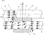
- This means 6a is, for example, an end face 6a of the spacer 6 which connects a front side 6b of the spacer 6 facing away from the core tube 21 with a rear side 6c of the spacer 6 facing the core tube 21, said end face 6a being inclined to the second pipe layer 202, so that the part of the first medium S flowing along the pipe 20 of the first pipe layer 201 against the end face 6a is deflected by the end face 6a in the direction of the second pipe layer 202.
- the inclination of the end face 6a with respect to the first pipe layer 201 is characterized here by an acute angle W which the second end face 6a has of the second pipe layer 202 or the pipe sections of the second pipe layer 202 adjoining the spacer 6.
- a plurality of spacers 6 of the type described above is preferably provided between each two adjacent pipe layers 201, 202, ..., the number of spacers 6 arranged between two pipe layers 201, 202, different pipe layers are preferably arranged one above the other in the radial direction R so that the load of the pipe layers 201, 202,.
- the tubes 20 in the tube layers 201, 202,... can have different winding directions.
- the first medium S in the adjacent pipe layers 201, 202 can flow in a different direction along the respective pipe 20.
- the end face 6a of the respective spacer 6 is then aligned in such a way that the respective inwardly directed portion of the first medium S flows against the respective end face 6a.
- the at least one or the respective spacer 6 can have projections 61 which protrude outward in the radial direction R from an edge portion of a base 60 of the respective spacer 6. These projections 61 serve to produce a desired vertical spacing between the pipe windings in the respective pipe layer. Furthermore, the projections 61 can form part of the end face 6 a of the respective spacer 6. The end face 6a of the respective spacer 6 can thus be arranged at least in sections between the adjacent pipe sections of the pipe layer 201 located further out.
- the Figure 3 shows a further embodiment of the invention, in which the at least one spacer 6 has at least one guide element 62, for example in the form of a guide plate, which is fixed to a (e.g. bar-shaped) base 60 of the at least one spacer 6 that extends along the longitudinal axis L.
- the at least one spacer 6 has at least one guide element 62, for example in the form of a guide plate, which is fixed to a (e.g. bar-shaped) base 60 of the at least one spacer 6 that extends along the longitudinal axis L.
- the base 60 takes on the load-bearing function, that is, the (first) pipe layer 201 arranged further out is supported on the (second) pipe layer 202 below it via this base 60, while the guide element 62 preferably has the flow-guiding or deflecting function takes over and said means 6a of the spacer 6, which is designed here as an impact surface 6a of the guide element 62, which has an inclination towards the (second) pipe layer 202 located further inward in the radial direction R (or an inclination towards the adjacent pipe sections of the second pipe layer 202) . Due to the inclination, the impact surface 6a of the guide element 62 forms an acute angle W with the (second) pipe layer 202 located radially further inward.
- the guide element 62 can be a separate element that is fixed to the base 60 of the respective spacer 6, preferably on an end face 60a of the base 60, the rear side facing the core tube 21, on which the further inward (second) tube layer 202 rests, connects to a front side of the base 60, on which the further outward (first pipe layer) 201 rests.
- the guide element 62 can, however, also be embodied integrally with the base 60 (in one piece).
- Analogous to Figure 2 can also according to Figure 3
- a plurality of spacers 6 can be provided, the spacers 6 from different pipe layers preferably being arranged one above the other in the radial direction R (see above).
- FIG 3 a situation is shown in which the flow direction of that part of the first medium S which flows along the pipe 20 of the respective pipe layer 201, 202
- the respective guide element 62 is provided or fixed on a downstream end face 60a of the base 60 of the respective spacer 6 in relation to the flow direction of the part of the first medium S to be deflected.
- Said baffle surface 6a is in particular facing the respective base 60 and in particular ensures a deflection of a part of the first medium S after this part has passed the respective base 60 on the rear side of the respective base 60.
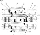
- Figure 4 shows a modification of the guide elements 62, here in contrast to Figure 3 the guide elements 62 are each provided on an upstream end face 60a of the base 60 of the respective spacer 6, and here the impact surface 6a of the respective guide element 62 from the associated base 60 is turned away and has an inclination with respect to the (second) pipe layer 202 located further inward, so that it encloses an acute angle W with it.
- the guide element 62 of the respective spacer 6 extends in sections between adjacent pipe sections of the pipe layer 202 located further inside.
- the respective spacer 6 can be used in both embodiments ( Fig. 3 and Fig. 4 ) also have a corresponding plurality of guide elements 62, which then each protrude into the space between two adjacent pipe sections of the pipe layer 202,.
- FIG. 5 shows Figure 5 an embodiment of spacers 6 according to the invention which, as before, are arranged between adjacent pipe layers 201, 202, ... of the heat exchanger 1 (see above), the flow-guiding means 6a being formed here by channels 6a (or having such channels), each of which are designed to direct a portion of the first medium S flowing from top to bottom along the first or outer pipe layer 201 in the direction of the second or radially further inward pipe layer 202.
- the said channels preferably slope towards the (second) pipe layer 202 located further inside.
- the grooves 6a can be provided, for example, on an end face 60a of the respective spacer 6 or a base of the respective spacer 6.
- the spacers 6 can furthermore in turn have projections 61 protruding from the respective base 60 in the radial direction R, which define a vertical distance between adjacent pipe windings or adjacent pipe sections of the pipes 20 in the direction of the longitudinal axis L of the jacket.
- the spacers 60 can only have the said grooves 6a as flow-guiding means. Said grooves 6a, however, can also be used in the spacers 6 of the Figures 1 to 4 be available as additional flow-guiding components.
Landscapes
- Engineering & Computer Science (AREA)
- Physics & Mathematics (AREA)
- Thermal Sciences (AREA)
- Mechanical Engineering (AREA)
- General Engineering & Computer Science (AREA)
- Heat-Exchange Devices With Radiators And Conduit Assemblies (AREA)
Description
- Die Erfindung betrifft einen gewickelten Wärmeübertrager.
- Ein derartiger Wärmeübertrager dient zur indirekten Wärmeübertragung zwischen zumindest einem ersten und einem zweiten Medium und weist einen Mantelraum zur Aufnahme des ersten Mediums auf, sowie ein im Mantelraum angeordnetes Rohrbündel mit einer Mehrzahl an Rohren zur Aufnahme des zweiten Mediums, wobei jene Rohre in mehreren Rohrlagen helikal auf ein Kernrohr des Wärmeübertragers gewickelt sind.
DE-A-1939564 offenbart einen solchen Wärmeübertrager und weiterhin einen Wärmeübertrager gemäß dem Oberbegriff des Anspruchs 1. - Zwischen den Rohrlagen sind bevorzugt Abstandshalter vorgesehen, über die sich die jeweilige Rohrlage auf der darunterliegenden Rohrlagen abstützt.
- Im Hinblick auf die Verteilung des im Mantelraum geführten ersten Mediums auf das Rohrbündel ist von besonderer Wichtigkeit, dass das erste Medium möglichst gleichmäßig auf das Rohrbündel verteilt wird, um eine effiziente Wärmeübertragung gewährleisten zu können.
- Diesbezüglich hat sich herausgestellt, dass das mantelseitig geführte fluide erste Medium aufgrund verschiedener Effekte im Mantelraum nach außen zu den (in radialer Richtung des Rohrbündels) äußeren Rohrlagen geleitet wird. Eine der Ursachen hierfür ist die Zentrifugalkraft, die aufgrund der helikalen Wicklung der einzelnen Rohre des Rohrbündels des Wärmeübertragers auf die entlang der Oberflächen der Rohre strömenden Teile des ersten Mediums wirkt. Hierdurch werden diese Teile des ersten Mediums in radialer Richtung des Rohrbündels nach außen hin zu den äußeren Rohrlagen gedrängt. Dies hat zur Folge, dass auch bei einer perfekten Verteilung des ersten Mediums auf die Oberseite des Rohrbündels eine Ungleichverteilung des ersten Mediums zu Gunsten der äußeren Rohrlagen erzeugt wird.
- Hiervon ausgehend liegt daher der vorliegenden Erfindung die Aufgabe zugrunde, einen Wärmeübertrager der eingangs genannten Art zu schaffen, der der vorgenannten Problematik entgegenwirkt.
- Dieses Problem wird durch einen Wärmeübertrager mit den Merkmalen des Anspruchs 1 gelöst. Vorteilhafte Ausgestaltungen des erfindungsgemäßen gewickelten Wärmeübertragers sind in den Unteransprüchen angegeben und werden nachfolgend beschrieben.
- Demnach wird ein Wärmeübertrager zur indirekten Wärmeübertragung zwischen einem ersten und einem zweiten Medium bereitgestellt mit einem Mantelraum zur Aufnahme des ersten Mediums, einem im Mantelraum angeordneten Rohrbündel mit einer Mehrzahl an Rohren zur Aufnahme des zweiten Mediums, wobei das jeweilige Rohr helikal auf ein Kernrohr gewickelt ist, so dass das Rohrbündel mehrere aufeinander angeordnete Rohrlagen aufweist, und zumindest einem Abstandshalter, über den sich eine in radialer Richtung des Rohrbündels weiter außen gelegene erste Rohrlage des Rohrbündels an einer benachbarten, in radialer Richtung des Rohrbündels weiter innen gelegenen zweiten Rohrlage abstützt.
- Erfindungsgemäß weist der mindestens eine Abstandshalter ein strömungsleitendes Mittel auf. Mit diesem wird bewirkt, dass ein im Mantelraum entlang der ersten (äußeren) und/oder der zweiten (inneren) Rohrlage strömender Teil des ersten Mediums in Richtung auf die radial weiter innen gelegene Rohrlage abgelenkt wird.
- Gemäß einer ersten Alternative weist das strömungsleitende Mittel eine Stirnseite des Abstandshalters auf, die eine dem Kernrohr abgewandte Vorderseite des Abstandshalters mit einer dem Kernrohr zugewandten Rückseite des Abstandshalters verbindet, wobei die Stirnseite eine Neigung hin zur zweiten Rohrlage aufweist, so dass ein entlang des Rohres der ersten Rohrlage gegen die Stirnseite strömender Teil des ersten Mediums durch die Stirnseite in Richtung auf die zweite Rohrlage abgelenkt wird.
- Gemäß einer zweiten Alternative weist das strömungsleitende Mittel zumindest ein Leitelement auf, das an einer entlang der Längsachse erstreckten Basis des Abstandshalters festgelegt ist, über die sich die erste Rohrlage an der zweiten Rohrlage abstützt, wobei das mindestens eine Leitelement eine Prallfläche ausbildet, die eine Neigung hin zur zweiten Rohrlage aufweist.
- Bei der weiter außen gelegenen Rohrlage muss es sich nicht zwangsläufig um die äußerste Rohrlage handeln. Es können natürlich eine Vielzahl an Rohrlagen bei dem erfindungsgemäßen Wärmeübertrager vorgesehen sein (siehe auch unten), wobei dann zwischen je zwei (in radialer Richtung) benachbarten Rohrlagen jeweils einer oder mehrere Abstandshalter mit dem besagten strömungsleitenden Mittel vorgesehen sein können, wobei die Strömung des betreffenden Teils des ersten Mediums immer von der jeweils radial weiter außen gelegenen (ersten) Rohrlage zur radial weiter innen gelegenen, benachbarten (zweiten) Rohrlage gelenkt wird. Die Abstandselemente mit dem besagten strömungsleitenden Mittel werden dabei so vorgesehen, dass eine möglichst gleichmäßige Verteilung des ersten Mediums auf das Rohrbündel erreicht wird (bezogen auf die gesamte Länge des Rohrbündels entlang der Längsachse des Mantels/Kernrohres des Wärmeübertragers). Das kann unter Umständen auch bedeuteten, dass nicht zwischen allen Rohrlagen derartige Abstandshalter vorgesehen werden, sondern nur zwischen bestimmten Rohrlagen (je nach zu erwartender Ungleichverteilung des ersten Mediums). Zwischen den übrigen Rohrlagen können dann z.B. herkömmliche Abstandshalter vorgesehen werden bzw. Abstandshalter, die den erfindungsgemäßen strömungsablenkenden Effekt nicht oder in einem wesentlich geringeren Ausmaß zeigen.
- Durch die Erfindung wird mit Vorteil der Ungleichverteilung zugunsten der äußeren Rohrlagen entgegengewirkt, sodass im Ergebnis das mantelseitige Kühlmittel bzw. das erste Medium besser verteilt wird und entsprechend die Leistung des gewickelten Wärmeübertragers verbessert wird.
- Erfindungsgemäß ist gemäß der ersten Alternative, wie vorstehend bereits beschrieben vorgesehen, dass das strömungsleitende Mittel eine Stirnseite des mindestens einen Abstandshalters aufweist. Bei dieser Stirnseite handelt es sich vorzugsweise um einen integralen Bestandteil des mindestens einen Abstandshalters bzw. eine einstückig mit dem Abstandshalter geformte Seite des Abstandshalters. Hierbei verbindet die Stirnseite eine dem Kernrohr abgewandte Vorderseite des Abstandshalters mit einer dem Kernrohr zugewandten Rückseite des Abstandshalters. Die Stirnseite erstreckt sich also im Wesentlichen entlang der radialen Richtung des Rohrbündels und weist dabei insbesondere eine Neigung gegenüber der radialen Richtung auf.
- Weiterhin kann sich die besagte Stirnseite auch abschnittsweise zwischen je zwei benachbarten Rohrabschnitten der ersten Rohrlage erstrecken, wobei diese Abschnitte der Stirnseite jeweils zu einem Vorsprung des Abstandselementes gehören können, wobei diese Vorsprünge jeweils zwischen zwei benachbarten Rohrabschnitten bzw. Rohrwicklungen der ersten Rohrlage liegen und jeweils von einem Randabschnitt einer Basis des mindestens einen Abstandshalters in radialer Richtung des Rohrbündels abstehen). Durch diese Vorsprünge wird somit der vertikale Abstand der Rohrwicklungen in der jeweiligen Rohrlage fixiert.
- Erfindungsgemäß ist gemäß der ersten Alternative vorgesehen, dass die besagte Stirnseite des mindestens einen Abstandshalters zum Beeinflussen bzw. Ablenken der Strömung des ersten Mediums eine Neigung hin zur zweiten Rohrlage aufweist bzw. eine Neigung gegenüber einer tangentialen Richtung der an den Abstandshalter anliegenden Rohrabschnitte der zweiten Rohrlage, so dass der entlang des Rohres der ersten Rohrlage gegen die Stirnseite des mindestens einen Abstandshalters strömende Teil des ersten Mediums durch die Stirnseite in Richtung auf die zweite Rohrlage abgelenkt wird.
- Vorzugsweise ist vorgesehen, dass sich das Kernrohr entlang einer Längsachse erstreckt, die vorzugsweise - bezogen auf einen bestimmungsgemäß angeordneten Wärmeübertrager - parallel zur Vertikalen orientiert ist.
- Bevorzugt weist der Wärmeübertrager weiterhin einen den Mantelraum umgebenden Mantel auf, der sich koaxial zum Kernrohr entlang der besagten Längsachse erstreckt.
- Vorzugsweise ist weiterhin vorgesehen, dass sich der mindestens eine Abstandshalter bzw. die besagte, strömungsbeeinflussende Stirnseite des Abstandshalters entlang der Längsachse erstreckt.
- Gemäß der zweiten Alternative weist das strömungsleitende Mittel zumindest ein Leitelement auf, zum Beispiel in Form zumindest eines Leitblechs, das an einer entlang der Längsachse erstreckten Basis des Abstandshalters festgelegt ist, über die sich die erste Rohrlage an der zweiten Rohrlage abstützt. Hierbei übernimmt also jene Basis die Herstellung des Abstandes zwischen den einzelnen Rohrlagen bzw. das Abtragen der Last der jeweils äußeren Rohrlage auf die darunterliegende Rohrlage, während das mindestens eine Leitelement bevorzugt lediglich eine strömungsleitende Funktion übernimmt.
- Weiterhin ist gemäß der zweiten Alternative vorgesehen, dass das mindestens eine Leitelement eine Prallfläche ausbildet, auf die der besagte abzulenkende Teil des ersten Mediums auftrifft, wobei jene Prallfläche wiederum eine Neigung hin zur zweiten Rohrlage aufweist (bzw. eine Neigung gegenüber einer tangentialen Richtung der an den Abstandshalter anliegenden Rohrabschnitte der zweiten Rohrlage).
- Vorzugsweise ist vorgesehen, dass sich das Leitelement abschnittsweise zwischen benachbarten Rohrabschnitten der zweiten Rohrlage bzw. der radial weiter innen gelegenen Rohrlage erstreckt.
- Anstelle eines Leitelementes kann der mindestens eine Abstandshalter auch mehrere Leitelemente aufweisen, die entlang der Längsachse an der Basis festgelegt sind, so dass zwischen je zwei in Richtung der Längsachse benachbarten Leitelementen eine Lücke vorhanden ist. Die einzelnen Leitelemente erstrecken sich dann abschnittsweise zwischen je zwei zugeordneten Rohrabschnitten der zweiten Rohrlage bzw. ragen in einen Zwischenraum zwischen den beiden Rohrabschnitten hinein.
- Weiterhin ist gemäß einer bevorzugten Ausführungsform vorgesehen, dass das mindestens eine Leitelement (oder die mehreren Leitelemente) bezogen auf die Strömungsrichtung des ersten Mediums an einem stromauf oder stromab gelegenen Abschnitt der Basis des mindestens einen Abstandshalters angeordnet ist, insbesondere an einer Stirnseite der Basis, die eine Vorderseite der Basis mit einer Rückseite der Basis verbindet, wobei die Rückseite dem Kernrohr zugewandt ist.
- Weiterhin ist gemäß einer bevorzugten Ausführungsform vorgesehen, dass das besagte Mittel durch eine Mehrzahl an im Abstandshalter ausgebildeten Rinnen gebildet ist oder solche Rinnen aufweist. Die Rinnen erstrecken sich dabei jeweils entlang der radialen Richtung nach innen, wobei Sie nach innen hin abfallen, so dass ein entlang der ersten Rohrlage insbesondere von oben nach unten strömenden Teil des ersten Mediums in die Rinnen gelangen kann und in diesen nach innen zur zweiten Rohrlage hin abgelenkt wird. Die Rinnen sind dabei z.B. an einer Stirnseite des jeweiligen Abstandshalters ausgebildet, gegen die das entlang der ersten Rohrlage bzw. entlang des Rohres der ersten Rohrlage strömende erste Medium strömt bzw. an der das erste Medium von oben nach unten herabströmt.
- Die oben genannten möglichen strömungsleitenden Komponenten (z.B. Stirnseiten, Leitelemente, Rinnen) können in einzelnen Ausführungsformen auch in beliebiger Weise miteinander kombiniert werden. Ein Abstandshalter kann also eine, zwei oder drei der besagten Komponenten zur Strömungslenkung aufweisen.
- Weiterhin ist gemäß einer bevorzugten Ausführungsform vorgesehen, dass der Wärmeübertrager eine Mehrzahl an Abstandselementen zwischen der ersten und der zweiten Rohrlage aufweist, wobei die Abstandselemente jeweils ein strömungsleitendes Mittel aufweisen, das gemäß einer der hierin beschriebenen bzw. beanspruchten Ausführungsformen ausgebildet ist.
- Weiterhin ist gemäß einer bevorzugten Ausführungsform vorgesehen, dass der Wärmeübertrager Abstandselemente zwischen mehreren oder zwischen allen benachbarten Rohrlagen aufweist, wobei das jeweilige Abstandselement bevorzugt ein strömungsleitendes Mittel aufweist, das gemäß einer der hierein beschriebenen bzw. beanspruchten Ausführungsformen ausgebildet ist.
- Weiterhin ist gemäß einer bevorzugten Ausführungsform vorgesehen, dass die Anzahl der zwischen den benachbarten Rohrlagen angeordneten Abstandshalter konstant ist, wobei jeweils mehrere Abstandshalter zum Abstützen der Rohrlagen in einer radialen Richtung des Rohrbündels übereinander angeordnet sind. Auf diese Weise kann das Gewicht aller Rohrlagen über die Abstandshalter abgestützt werden, ohne die Rohre einzelner Rohrlagen zu beschädigen.
- Weitere Einzelheiten und Vorzüge der Erfindung sollen durch die nachfolgenden Figurenbeschreibungen von Ausführungsbeispielen anhand der Figuren erläutert werden.
- Es zeigen:
- Fig. 1
- eine teilweise geschnittene Ansicht eines erfindungsgemäßen gewickelten Wärmeübertragers mit strömungsbeeinflussenden Abstandshaltern;
- Fig. 2
- eine Ausführungsform der erfindungsgemäßen Abstandshalter, wobei der jeweilige Abstandshalter eine geneigte Stirnseite zum Ablenken des ersten Mediums aufweist;
- Fig. 3
- eine weitere Ausführungsform der erfindungsgemäßen Abstandshalter, wobei der jeweilige Abstandshalter ein Leitelement zum Ablenken des ersten Mediums aufweist;
- Fig. 4
- eine Abwandlung der in der
Figur 3 gezeigten Ausführungsform; und - Fig. 5
- eine weitere Ausführungsform von erfindungsgemäßen Abstandshaltern, die Rinnen zum Ablenken des ersten Mediums aufweisen.
-
Fig. 1 zeigt einen gewickelten Wärmeübertrager 1. Dieser weist einen Mantel 10 auf, der einen Mantelraum M des Wärmeübertragers 1 umschließt. Der Mantel 10 erstreckt sich entlang einer vertikalen Längs- bzw. Zylinderachse L und umgibt ein im Mantelraum M angeordnetes Rohrbündel 2, das bezogen auf die Längsachse L von oben mit einem fluiden ersten Medium S zu beaufschlagen ist, so dass dieses in indirekte Wärmeübertragung mit zumindest einem in dem Rohrbündel 2 geführten zweiten Medium S' zu treten. Das Rohrbündel 2 wird dabei aus mehreren Rohren 20 gebildet, die jeweils helikal um ein Kernrohr 21 gewickelt sind, so dass das Rohrbündel mehrere in radialer Richtung R des Rohrbündels 2 übereinander angeordnete Rohrlagen 201, 202,... aufweist (vgl.Figuren 2 bis 4 ). Hierbei erstreckt sich das Kernrohr 21 koaxial zum Mantel 10, wobei die radiale Richtung R des Rohrbündels 2 senkrecht auf der Längsachse L bzw. dem Kernrohr 21 steht und nach außen zum Mantel 10 weist. - Die solchermaßen gebildeten und in radialer Richtung R des Rohrbündels 2 übereinander angeordneten Rohrlagen 201, 202,... stützen sich über entlang der Längsachse L erstreckte Abstandshalter 6, die vorzugsweise als Stege ausgebildet sind, aneinander ab, so dass die Lasten der Rohrlagen 201, 202,... über die Abstandshalter 6 in das Kernrohr 21 eingeleitet werden. Das Rohrbündel 2 kann des Weiteren von einem sogenannten Hemd 3 umgeben sein, um zu verhindern, dass das erste Medium S außen am Rohrbündel 2 vorbeifließen kann. Das erste Medium S kann z.B. über einen lateral am Mantel 10 vorgesehenen Stutzen 101 in den Mantelraum M eingespeist sowie über einen weiteren lateral am Mantel 10 vorgesehenen Stutzen 102 aus dem Mantelraum M abgezogen werden. Zum möglichst gleichmäßigen Verteilen des ersten Mediums S auf eine quer zur Längsachse L erstreckte Oberseite O des Rohrbündels 2 kann im Mantelraum M oberhalb des Rohrbündels 2 eine hier nicht näher gezeigte Verteileinrichtung, z.B. von bekannter Art, vorgesehen sein. Das im Rohrbündel 2 geführte zweite Medium S' kann des Weiteren über einen am Mantel 10 vorgesehen Stutzen 103 in das Rohrbündel 2 eingeleitet sowie über einen weiteren am Mantel 10 vorgesehenen Stutzen 105 aus dem Rohrbündel 2 abgezogen werden. Für den Fall, dass mehrere Medien im Rohrbündel 2 geführt werden sollen, können die Rohre 20 zu entsprechenden Gruppen 104 zusammengefasst sein, die dann jeweils eines der Medien führen.
- Aufgrund der oben genannten Effekte kann auch bei gleichmäßiger Verteilung des ersten Mediums S auf die Oberseite O des Rohrbündels 2 eine Ungleichverteilung des ersten Mediums S in der radialen Richtung R des Rohrbündels 2 erfolgen.
- Um dieser Ungleichverteilung entgegen zu wirken, ist erfindungsgemäß vorgesehen, dass der Wärmeübertrager 1 zumindest einen Abstandshalter 6 aufweist, über den sich eine in der radialen Richtung R des Rohrbündels 2 weiter außen gelegene erste Rohrlage 201 an einer in der radialen Richtung R weiter innen gelegenen zweiten Rohrlage 202 abstützt, wobei der Abstandshalter 6 ein strömungsleitendes Mittel 6a aufweist, das dazu konfiguriert ist, einen im Mantelraum M entlang eines Rohres 20 der ersten Rohrlage 201 strömenden Teil des ersten Mediums S in Richtung auf die weiter innen gelegene zweite Rohrlage 202 abzulenken.
- Gemäß dem in der
Figur 2 gezeigten Ausführungsbeispiel handelt es sich bei diesem Mittel 6a z.B. um eine Stirnseite 6a des Abstandshalters 6, die eine dem Kernrohr 21 abgewandte Vorderseite 6b des Abstandshalters 6 mit einer dem Kernrohr 21 zugewandten Rückseite 6c des Abstandshalters 6 verbindet, wobei die besagte Stirnseite 6a eine Neigung hin zur zweiten Rohrlage 202 aufweist, so dass der entlang des Rohres 20 der ersten Rohrlage 201 gegen die Stirnseite 6a strömende Teil des ersten Mediums S durch die Stirnseite 6a in Richtung auf die zweite Rohrlage 202 abgelenkt wird. Die Neigung der Stirnseite 6a gegenüber der ersten Rohrlage 201 ist hierbei durch einen spitzen Winkel W charakterisiert, den die zweite Stirnseite 6a mit der zweiten Rohrlage 202 bzw. den an den Abstandshalter 6 angrenzenden Rohrabschnitten der zweiten Rohrlage 202 einschließt. - Bevorzugt ist zwischen je zwei benachbarten Rohrlagen 201, 202,... eine Mehrzahl an Abstandshaltern 6 der vorstehend beschriebenen Art vorgesehen, wobei die Anzahl der zwischen zwei Rohrlagen 201, 202,... angeordneten Abstandshalter 6 vorzugsweise konstant ist und die Abstandshalter 6 aus verschiedenen Rohrlagen vorzugsweise in der radialen Richtung R übereinander angeordnet sind, damit die Last der übereinander angeordneten Rohrlagen 201, 202,... sicher über die Abstandshalter 6 zum Kernrohr 21 abgetragen werden kann.
- Wie in der
Figur 2 weiterhin gezeigt ist, können die Rohre 20 in den Rohrlagen 201, 202,... einen unterschiedlichen Wicklungssinn aufweisen. Dies hat zur Folge, dass das erste Medium S in den benachbarten Rohrlagen 201, 202 entlang des jeweiligen Rohres 20 in eine unterschiedliche Richtung fließen kann. Die Stirnseite 6a des jeweiligen Abstandshalters 6 ist dann so ausgerichtet, dass der jeweilige nach innen zu lenkende Anteil des ersten Mediums S gegen die jeweilige Stirnseite 6a strömt. - Wie weiterhin in
Figur 2 gezeigt ist, kann der mindestens eine bzw. der jeweilige Abstandshalter 6 Vorsprünge 61 aufweisen, die von einem Randabschnitt einer Basis 60 des jeweiligen Abstandshalters 6 in der radialen Richtung R nach außen abstehen. Diese Vorsprünge 61 dienen zur Herstellung eines gewünschten vertikalen Abstandes der Rohrwicklungen in der jeweiligen Rohrlage. Weiterhin können die Vorsprünge 61 einen Teil der Stirnseite 6a des jeweiligen Abstandshalters 6 bilden. Die Stirnseite 6a des jeweiligen Abstandshalters 6 kann also zumindest abschnittsweise zwischen den benachbarten Rohrabschnitten der jeweils weiter außen gelegenen Rohrlage 201 angeordnet sein. - Die
Figur 3 zeigt eine weitere Ausführungsform der Erfindung, bei der der mindestens eine Abstandshalter 6 zumindest ein Leitelement 62, z.B. in Form eines Leitbleches aufweist, das an einer entlang der Längsachse L erstreckten (z.B. stegförmigen) Basis 60 des mindestens einen Abstandshalters 6 festgelegt ist, wobei hier bevorzugt die Basis 60 die lastabtragende Funktion übernimmt, d.h., die jeweils weiter außen angeordnete (erste) Rohrlage 201 stützt sich über diese Basis 60 an der darunter liegenden (zweiten) Rohrlage 202 ab, während das Leitelement 62 bevorzugt die strömungsleitende bzw. -ablenkende Funktion übernimmt und das besagte Mittel 6a des Abstandshalters 6 ausbildet, das hier als eine Prallfläche 6a des Leitelements 62 ausgeführt ist, die eine Neigung hin zu der in radialer Richtung R weiter innen liegenden (zweiten) Rohrlage 202 aufweist (bzw. eine Neigung gegenüber den angrenzenden Rohrabschnitten der zweiten Rohrlage 202). Aufgrund der Neigung schließt die Prallfläche 6a des Leitelementes 62 einen spitzen Winkel W mit der jeweils radial weiter innen liegenden (zweiten) Rohrlage 202 ein. - Das Leitelement 62 kann ein separates Element sein, das an der Basis 60 des jeweiligen Abstandshalters 6 festgelegt ist, und zwar vorzugsweise an einer Stirnseite 60a der Basis 60, die eine dem Kernrohr 21 zugewandte Rückseite, an der die weiter innen gelegene (zweite) Rohrlage 202 anliegt, mit einer Vorderseite der Basis 60 verbindet, an der die weiter außen gelegene (erste Rohrlage) 201 anliegt. Das Leitelement 62 kann jedoch auch integral mit der Basis 60 (aus einem Stück) ausgeführt sein.
- Analog zur
Figur 2 kann auch gemäßFigur 3 wiederum eine Mehrzahl an Abstandshaltern 6 vorgesehen sein, wobei die Abstandshalter 6 aus verschiedenen Rohrlagen bevorzugt in der radialen Richtung R übereinander angeordnet sind (siehe oben). - Des Weiteren ist auch in
Figur 3 eine Situation gezeigt, bei der die Strömungsrichtung desjenigen Teils des ersten Mediums S, der entlang des Rohres 20 der jeweiligen Rohrlage 201, 202,... fließt, aufgrund des Wicklungssinns des jeweiligen Rohres 20 von Rohrlage zu Rohrlage unterschiedlich ist, wobei gemäßFigur 3 bevorzugt vorgesehen ist, dass das jeweilige Leitelement 62 bezogen auf die Strömungsrichtung des abzulenkenden Teils des ersten Mediums S an einer stromab gelegenen Stirnseite 60a der Basis 60 des jeweiligen Abstandhalters 6 vorgesehen bzw. festgelegt ist. Die besagte Prallfläche 6a ist hierbei der jeweiligen Basis 60 insbesondere zugewandt und besorgt insbesondere eine Ablenkung eines Teils des ersten Mediums S nach dem dieser Teil die jeweilige Basis 60 an der Rückseite der jeweiligen Basis 60 passiert hat. -
Figur 4 zeigt eine Abwandlung der Leitelemente 62, wobei hier im Unterschied zurFigur 3 die Leitelemente 62 jeweils an einer stromauf gelegenen Stirnseite 60a der Basis 60 des jeweiligen Abstandshalters 6 vorgesehen sind, und wobei hier die Prallfläche 6a des jeweiligen Leitelementes 62 von der zugeordneten Basis 60 abgewandt ist und gegenüber der jeweils weiter innen gelegenen (zweiten) Rohrlage 202 eine Neigung aufweist, so dass sie mit dieser einen spitzen Winkel W einschließt. - Sowohl bei der Ausführungsform gemäß
Figur 3 als auch bei der Ausführungsform gemäßFigur 4 ist bevorzugt vorgesehen, dass sich das Leitelement 62 des jeweiligen Abstandshalters 6 abschnittsweise zwischen benachbarten Rohrabschnitten der jeweils weiter innen gelegenen Rohrlage 202 erstreckt. Anstelle eines Leitelementes 62 kann der jeweilige Abstandshalter 6 in beiden Ausführungsformen (Fig. 3 undFig. 4 ) auch eine entsprechende Mehrzahl an Leitelementen 62 aufweisen, die dann jeweils in den Zwischenraum zwischen zwei benachbarten Rohrabschnitten der jeweils weiter innen angeordneten Rohrlage 202,... hineinstehen. - Schließlich zeigt
Figur 5 eine Ausführungsform von erfindungsgemäßen Abstandshaltern 6, die wie zuvor zwischen benachbarten Rohrlagen 201, 202,... des Wärmeübertragers 1 (siehe oben) angeordnet sind, wobei das strömungsleitende Mittel 6a hier durch Rinnen 6a gebildet ist (oder solche Rinnen aufweist), die jeweils dazu ausgebildet sind, einen entlang der ersten bzw. äußeren Rohrlage 201 von oben nach unten strömenden Teil des ersten Mediums S in Richtung auf die zweite bzw. radial weiter innen gelegene Rohrlage 202 zu lenken. Hierzu fallen die besagten Rinnen vorzugsweise zur weiter innen gelegenen (zweiten) Rohrlage 202 ab. Die Rinnen 6a können z.B. an einer Stirnseite 60a des jeweiligen Abstandshalters 6 bzw. einer Basis des jeweiligen Abstandshalters 6 vorgesehen sein. Die Abstandshalter 6 können des Weiteren wiederum von der jeweiligen Basis 60 in der radialen Richtung R abragende Vorsprünge 61 aufweisen, die einen vertikalen Abstand benachbarter Rohrwicklungen bzw. benachbarter Rohrabschnitte der Rohre 20 in Richtung der Längsachse L des Mantels definieren. - Die Abstandshalter 60 können lediglich die besagten Rinnen 6a als strömungsleitendes Mittel aufweisen. Die besagten Rinnen 6a können jedoch auch bei den Abstandshaltern 6 der
Figuren 1 bis 4 als zusätzliche strömungsleitende Komponenten vorhanden sein. -
1 Gewickelter Wärmeübertrager 2 Rohrbündel 3 Hemd 6 Abstandshalter 6a Mittel (z.B. Stirnseite, Prallfläche, Rinne) 6b Vorderseite 6c Rückseite 10 Mantel 20 Rohre 21 Kernrohr 60 Basis 61 Vorsprung 62 Leitelement 60a Stirnseite Basis 101, 102, 103, 105 Stutzen 104 Rohrgruppe 201,202 Benachbarte Rohrlagen M Mantelraum O Oberseite S Erstes Medium S' Zweites Medium R Radiale Richtung L Längsachse (Vertikale) W Winkel
Claims (10)
- Wärmeübertrager (1) zur indirekten Wärmeübertragung zwischen einem ersten und einem zweiten Medium (S, S'), mit- einem Mantelraum (M) zur Aufnahme des ersten Mediums (S),- einem im Mantelraum (M) angeordneten Rohrbündel (2) mit einer Mehrzahl an Rohren (20) zur Aufnahme des zweiten Mediums (S'), wobei das jeweilige Rohr (20) helikal auf ein Kernrohr gewickelt ist, so dass das Rohrbündel (2) mehrere aufeinander angeordnete Rohrlagen (201, 202, 203) aufweist, und- zumindest einem Abstandshalter (6), über den sich eine in radialer Richtung (R) des Rohrbündels (2) weiter außen gelegene erste Rohrlage (201) des Rohrbündels (2) an einer benachbarten, in radialer Richtung (R) des Rohrbündels (2) weiter innen gelegenen zweiten Rohrlage (202) abstützt, und wobei der mindestens eine Abstandshalter (6) ein strömungsleitendes Mittel (6a) aufweist,dadurch gekennzeichnet, dass
das Mittel (6a) eine Stirnseite (6a) des Abstandshalters (6) aufweist, die eine dem Kernrohr (21) abgewandte Vorderseite (6b) des Abstandshalters (6) mit einer dem Kernrohr (21) zugewandten Rückseite (6c) des Abstandshalters (6) verbindet, wobei die Stirnseite (6a) eine Neigung hin zur zweiten Rohrlage (202) aufweist, so dass ein entlang des Rohres (20) der ersten Rohrlage (201) gegen die Stirnseite (6a) strömender Teil des ersten Mediums (S) durch die Stirnseite (6a) in Richtung auf die zweite Rohrlage (202) abgelenkt wird,
oder dass,
das Mittel (6a) zumindest ein Leitelement (62) aufweist, das an einer entlang der Längsachse (L) erstreckten Basis (60) des Abstandshalters (6) festgelegt ist, über die sich die erste Rohrlage (201) an der zweiten Rohrlage (202) abstützt, wobei das mindestens eine Leitelement (62) eine Prallfläche (6a) ausbildet, die eine Neigung hin zur zweiten Rohrlage (202) aufweist. - Wärmeübertrager nach Anspruch 1, dadurch gekennzeichnet, dass sich das mindestens eine Leitelement (62) abschnittsweise zwischen benachbarten Rohrabschnitten der zweiten Rohrlage (202) erstreckt.
- Wärmeübertrager nach einem der Ansprüche 1 bis 2, dadurch gekennzeichnet, dass das mindestens eine Leitelement (62) bezogen auf die Strömungsrichtung des ersten Mediums (S) an einem stromauf oder stromab gelegenen Randabschnitt (60a) des Abstandshalters (6) angeordnet ist.
- Wärmeübertrager nach einem der vorhergehenden Ansprüche, dadurch gekennzeichnet, dass sich das Kernrohr (21) entlang einer Längsachse (L) erstreckt.
- Wärmeübertrager nach Anspruch 4, dadurch gekennzeichnet, dass der Wärmeübertrager (1) einen den Mantelraum (M) umgebenden Mantel (10) aufweist, der sich koaxial zum Kernrohr (21) entlang der Längsachse (L) erstreckt.
- Wärmeübertrager nach Anspruch 4 oder 5, dadurch gekennzeichnet, dass sich der mindestens eine Abstandshalter (6) und/oder das besagte Mittel (6a) entlang der Längsachse (L) erstreckt.
- Wärmeübertrager nach einem der vorhergehenden Ansprüche, dadurch gekennzeichnet, dass das Mittel eine Mehrzahl an in dem mindestens einen Abstandshalter (6) vorgesehenen Rinnen (6a) aufweist, die dazu ausgebildet sind, einen entlang der ersten Rohrlage (201) von oben nach unten strömenden Teil des ersten Mediums (S) in Richtung auf die zweite Rohrlage (202) zu lenken.
- Wärmeübertrager nach einem der vorhergehenden Ansprüche, dadurch gekennzeichnet, dass der Wärmeübertrager (1) eine Mehrzahl an Abstandselementen (6) zwischen der ersten und der zweiten Rohrlage (201, 202) aufweist, wobei die Abstandselemente (6) jeweils ein strömungsleitendes Mittel (6a) gemäß einem der vorhergehenden Ansprüche aufweisen.
- Wärmeübertrager nach einem der vorhergehenden Ansprüche, dadurch gekennzeichnet, dass der Wärmeübertrager (1) Abstandselemente (6) zwischen mehreren oder zwischen allen benachbarten Rohrlagen (201, 202, 203) des Wärmeübertragers (1) aufweist, wobei das jeweilige Abstandselement (6) ein strömungsleitendes Mittel (6a) nach einem der vorangehenden Ansprüche aufweist.
- Wärmeübertrager nach Anspruch 9, dadurch gekennzeichnet, dass die Anzahl der zwischen den benachbarten Rohrlagen (201, 202, 203) angeordneten Abstandshalter (6) konstant ist, wobei jeweils mehrere Abstandshalter (6) zum Abstützen der Rohrlagen (201, 202, 203) in einer radialen Richtung (R) des Rohrbündels (2) übereinander angeordnet sind.
Applications Claiming Priority (2)
| Application Number | Priority Date | Filing Date | Title |
|---|---|---|---|
| EP16000851 | 2016-04-14 | ||
| PCT/EP2017/025090 WO2017178120A1 (de) | 2016-04-14 | 2017-04-12 | Gewickelter wärmeübertrager |
Publications (2)
| Publication Number | Publication Date |
|---|---|
| EP3443287A1 EP3443287A1 (de) | 2019-02-20 |
| EP3443287B1 true EP3443287B1 (de) | 2021-12-08 |
Family
ID=55759435
Family Applications (1)
| Application Number | Title | Priority Date | Filing Date |
|---|---|---|---|
| EP17717327.5A Not-in-force EP3443287B1 (de) | 2016-04-14 | 2017-04-12 | Gewickelter wärmeübertrager |
Country Status (5)
| Country | Link |
|---|---|
| US (1) | US10823508B2 (de) |
| EP (1) | EP3443287B1 (de) |
| CN (1) | CN108885065B (de) |
| RU (1) | RU2727110C2 (de) |
| WO (1) | WO2017178120A1 (de) |
Families Citing this family (4)
| Publication number | Priority date | Publication date | Assignee | Title |
|---|---|---|---|---|
| WO2020083524A1 (de) * | 2018-10-23 | 2020-04-30 | Linde Aktiengesellschaft | Verfahren zur herstellung eines gewickelten wärmeübertragers |
| WO2020083523A1 (de) * | 2018-10-23 | 2020-04-30 | Linde Aktiengesellschaft | Verfahren zur herstellung eines gewickelten wärmeübertragers |
| EP3964372A1 (de) * | 2020-09-03 | 2022-03-09 | TI Automotive Technology Center GmbH | Rohranordnung für den transport von temperiermedien |
| WO2022117129A1 (en) * | 2020-12-01 | 2022-06-09 | Vysoké Učení Technické V Brně | Tubular shell heat exchanger with cross flow |
Family Cites Families (39)
| Publication number | Priority date | Publication date | Assignee | Title |
|---|---|---|---|---|
| BE599070A (de) * | 1960-01-22 | |||
| US3286767A (en) * | 1964-10-01 | 1966-11-22 | Babcock & Wilcox Co | Tube support arrangement |
| DE1939564A1 (de) * | 1968-08-06 | 1970-02-12 | Atomic Power Construction Ltd | Aufhaengesystem fuer Vielfach-Rohranordnungen,insbesondere in Waermetauschern von Kernreaktoren |
| US3677339A (en) * | 1970-01-15 | 1972-07-18 | Alfred J Perrin | Coiled tube banks |
| DE2613745A1 (de) * | 1976-03-31 | 1977-10-06 | Linde Ag | Waermetauscher |
| SU901795A1 (ru) * | 1980-04-04 | 1982-01-30 | Предприятие П/Я Г-4882 | Спиральный теплообменник |
| DE3403429A1 (de) * | 1984-02-01 | 1985-08-08 | Karl 7298 Loßburg Hehl | Kuehlereinheit fuer kunststoff-spritzgiessmaschine |
| CH665020A5 (de) * | 1984-08-15 | 1988-04-15 | Sulzer Ag | Waermeuebertrager. |
| US5088192A (en) * | 1986-02-21 | 1992-02-18 | Aqua Systems, Inc. | Method of forming a shell and coil heat exchanger |
| US5228505A (en) * | 1986-02-21 | 1993-07-20 | Aqua Systems Inc. | Shell and coil heat exchanger |
| US5379832A (en) * | 1992-02-18 | 1995-01-10 | Aqua Systems, Inc. | Shell and coil heat exchanger |
| US5578231A (en) * | 1992-06-06 | 1996-11-26 | Barmag Ag | Heater for an advancing yarn |
| RU2050525C1 (ru) * | 1993-11-11 | 1995-12-20 | Лариса Ростиславовна Комарова | Теплообменник |
| US6076597A (en) * | 1997-12-31 | 2000-06-20 | Flowserve Management Company | Helical coil heat exchanger with removable end plates |
| RU2262054C2 (ru) * | 1999-02-01 | 2005-10-10 | Олесевич Алексей Кириллович | Теплообменный аппарат |
| JP2002097946A (ja) * | 2000-09-25 | 2002-04-05 | Honda Motor Co Ltd | 内燃機関の廃熱回収装置 |
| DE10123219A1 (de) * | 2001-05-12 | 2003-01-16 | Bosch Gmbh Robert | Wärmetauscher zum Erwärmen eines Produktes, insbesondere einer Masse zur Herstellung von Süßwaren |
| JP3524083B2 (ja) * | 2001-11-16 | 2004-04-26 | 核燃料サイクル開発機構 | 中間熱媒体を有するヘリカル型熱交換器 |
| RU2192593C1 (ru) * | 2001-12-11 | 2002-11-10 | Закрытое акционерное общество "ОРМА" | Спиральный теплообменник |
| US6827138B1 (en) * | 2003-08-20 | 2004-12-07 | Abb Lummus Global Inc. | Heat exchanger |
| DE112005001061T5 (de) * | 2004-05-11 | 2008-11-06 | Noritz Corporation, Kobe | Wärmetauscher und Wasserheizvorrichtung |
| US20060108107A1 (en) * | 2004-11-19 | 2006-05-25 | Advanced Heat Transfer, Llc | Wound layered tube heat exchanger |
| US10495383B2 (en) * | 2004-11-19 | 2019-12-03 | Modine Grenada Llc | Wound layered tube heat exchanger |
| US20090301699A1 (en) * | 2008-06-05 | 2009-12-10 | Lummus Novolent Gmbh/Lummus Technology Inc. | Vertical combined feed/effluent heat exchanger with variable baffle angle |
| GB2463482B (en) * | 2008-09-12 | 2012-05-02 | Tanjung Citech Uk Ltd | A heat exchange unit |
| US20100096115A1 (en) | 2008-10-07 | 2010-04-22 | Donald Charles Erickson | Multiple concentric cylindrical co-coiled heat exchanger |
| AU2013284326B2 (en) * | 2012-06-29 | 2017-07-27 | Waterco Limited | Heat exchanger |
| DE102012014101A1 (de) * | 2012-07-17 | 2014-01-23 | Linde Aktiengesellschaft | Gewickelter Wärmeübertrager |
| US20140262172A1 (en) * | 2013-03-14 | 2014-09-18 | Koch Heat Transfer Company, Lp | Tube bundle for shell-and-tube heat exchanger and a method of use |
| WO2015007375A1 (de) * | 2013-07-16 | 2015-01-22 | Linde Aktiengesellschaft | Wärmeübertrager mit elastischem element |
| HK1189328A2 (en) * | 2013-09-30 | 2014-05-30 | 香港现代科技有限公司 | Fluid heat exchanger and energy recovery device |
| CN104596333B (zh) * | 2013-10-31 | 2017-09-15 | 台达电子工业股份有限公司 | 热交换机 |
| SE538978C2 (sv) * | 2014-04-14 | 2017-03-07 | Milton Mogens | Värmeväxlare |
| US20160018168A1 (en) * | 2014-07-21 | 2016-01-21 | Nicholas F. Urbanski | Angled Tube Fins to Support Shell Side Flow |
| CN204404855U (zh) * | 2014-11-26 | 2015-06-17 | 中国海洋石油总公司 | 一种腔体内设置竖直隔板的缠绕管式换热器 |
| CA2882516C (en) * | 2015-02-20 | 2016-02-23 | Robert M. Myerholtz | Helical coil heating apparatus and method of operation |
| EP3128278B1 (de) * | 2015-08-06 | 2018-06-20 | Linde Aktiengesellschaft | Zufuhr und entnahme von rohrströmen mit zwischentemperatur bei gewickelten wärmeübertragern |
| DE102016005838A1 (de) * | 2016-05-12 | 2017-11-16 | Linde Aktiengesellschaft | Gewickelter Wärmeübertrager mit Einbauten zwischen Hemd und letzter Rohrlage |
| ITUA20163433A1 (it) * | 2016-05-13 | 2017-11-13 | Stefani S P A | Aletta per un pacco alettato per scambiatori di calore, nonché scambiatore di calore |
-
2017
- 2017-04-12 EP EP17717327.5A patent/EP3443287B1/de not_active Not-in-force
- 2017-04-12 CN CN201780018712.8A patent/CN108885065B/zh not_active Expired - Fee Related
- 2017-04-12 US US16/093,182 patent/US10823508B2/en active Active
- 2017-04-12 WO PCT/EP2017/025090 patent/WO2017178120A1/de not_active Ceased
- 2017-04-12 RU RU2018134268A patent/RU2727110C2/ru active
Non-Patent Citations (1)
| Title |
|---|
| None * |
Also Published As
| Publication number | Publication date |
|---|---|
| WO2017178120A1 (de) | 2017-10-19 |
| US10823508B2 (en) | 2020-11-03 |
| CN108885065A (zh) | 2018-11-23 |
| RU2018134268A3 (de) | 2020-05-27 |
| CN108885065B (zh) | 2020-12-01 |
| RU2018134268A (ru) | 2020-05-14 |
| US20190120559A1 (en) | 2019-04-25 |
| RU2727110C2 (ru) | 2020-07-20 |
| EP3443287A1 (de) | 2019-02-20 |
Similar Documents
| Publication | Publication Date | Title |
|---|---|---|
| EP2511642B1 (de) | Wärmetauscher mit zusätzlicher Flüssigkeitsregelung im Mantelraum | |
| EP0517750B1 (de) | Siedewasserkernreaktor und kernreaktorbrennelement für diesen siedewasserkernreaktor | |
| DE69003404T3 (de) | Mehrrohrtypwärmetauscher. | |
| EP2818821B1 (de) | Gewickelter Wärmeübertrager mit Kernrohrzuspeisung | |
| EP3455573B1 (de) | Gewickelter wärmeübertrager mit einbauten zwischen hemd und letzter rohrlage | |
| WO2017178120A1 (de) | Gewickelter wärmeübertrager | |
| DE102008054899A1 (de) | Stoffauflauf für eine Maschine zur Herstellung einer Faserstoffbahn | |
| EP3430338B1 (de) | Trenneinrichtung für gewickelte wärmeübertrager zum trennen einer gasförmigen phase von einer flüssigen phase eines zweiphasigen mantelseitig geführten mediums | |
| EP3128278B1 (de) | Zufuhr und entnahme von rohrströmen mit zwischentemperatur bei gewickelten wärmeübertragern | |
| EP3447425A1 (de) | Einbauten in einem gewickelten wärmeübertrager zur unterdrückung von gaswirbeln | |
| DE102005001952A1 (de) | Rohrbündelreaktor zur Durchführung exothermer oder endothermer Gasphasenreaktionen | |
| EP0027984A2 (de) | Siedewasserreaktor | |
| DE3406682C2 (de) | ||
| WO2017167458A1 (de) | Gewickelter wärmeübertrager | |
| EP1958756A1 (de) | Axial- oder Konuswendelverteiler für eine Blasfolienanlage sowie Herstellverfahren einer mehrlagigen Folie | |
| DE19513681A1 (de) | Untere Gitterplatte mit Auffangeinrichtung für Bruchstücke für einen Kernreaktor | |
| DE3219297C2 (de) | Wärmetauscher, insbesondere Heissgaskühler für Helium | |
| DE102019220059A1 (de) | Gehäuse eines fluidgekühlten PKW-Elektromotors | |
| EP3953654B1 (de) | Stegdesign - und anordnung zur verringerung einer radialen fehlverteilung in einem gewickelten wärmeübertrager | |
| DE102012014101A1 (de) | Gewickelter Wärmeübertrager | |
| WO2021052628A1 (de) | Entkoppelung der bündellagen bei gewickelten wärmeübertragern | |
| DE102018209441A1 (de) | Brennstoffzellenplatte | |
| EP3830510B1 (de) | Abstützung von rohren gewickelter wärmeübertrager | |
| DE102012005569A1 (de) | Wärmetauscher mit Sektionen | |
| DE102016103719B4 (de) | Vorrichtung zur Fluidführung |
Legal Events
| Date | Code | Title | Description |
|---|---|---|---|
| STAA | Information on the status of an ep patent application or granted ep patent |
Free format text: STATUS: UNKNOWN |
|
| STAA | Information on the status of an ep patent application or granted ep patent |
Free format text: STATUS: THE INTERNATIONAL PUBLICATION HAS BEEN MADE |
|
| PUAI | Public reference made under article 153(3) epc to a published international application that has entered the european phase |
Free format text: ORIGINAL CODE: 0009012 |
|
| STAA | Information on the status of an ep patent application or granted ep patent |
Free format text: STATUS: REQUEST FOR EXAMINATION WAS MADE |
|
| 17P | Request for examination filed |
Effective date: 20180910 |
|
| AK | Designated contracting states |
Kind code of ref document: A1 Designated state(s): AL AT BE BG CH CY CZ DE DK EE ES FI FR GB GR HR HU IE IS IT LI LT LU LV MC MK MT NL NO PL PT RO RS SE SI SK SM TR |
|
| AX | Request for extension of the european patent |
Extension state: BA ME |
|
| DAV | Request for validation of the european patent (deleted) | ||
| DAX | Request for extension of the european patent (deleted) | ||
| STAA | Information on the status of an ep patent application or granted ep patent |
Free format text: STATUS: EXAMINATION IS IN PROGRESS |
|
| 17Q | First examination report despatched |
Effective date: 20200401 |
|
| RAP1 | Party data changed (applicant data changed or rights of an application transferred) |
Owner name: LINDE GMBH |
|
| GRAP | Despatch of communication of intention to grant a patent |
Free format text: ORIGINAL CODE: EPIDOSNIGR1 |
|
| STAA | Information on the status of an ep patent application or granted ep patent |
Free format text: STATUS: GRANT OF PATENT IS INTENDED |
|
| INTG | Intention to grant announced |
Effective date: 20210322 |
|
| GRAJ | Information related to disapproval of communication of intention to grant by the applicant or resumption of examination proceedings by the epo deleted |
Free format text: ORIGINAL CODE: EPIDOSDIGR1 |
|
| STAA | Information on the status of an ep patent application or granted ep patent |
Free format text: STATUS: EXAMINATION IS IN PROGRESS |
|
| INTC | Intention to grant announced (deleted) | ||
| GRAP | Despatch of communication of intention to grant a patent |
Free format text: ORIGINAL CODE: EPIDOSNIGR1 |
|
| STAA | Information on the status of an ep patent application or granted ep patent |
Free format text: STATUS: GRANT OF PATENT IS INTENDED |
|
| INTG | Intention to grant announced |
Effective date: 20210923 |
|
| GRAS | Grant fee paid |
Free format text: ORIGINAL CODE: EPIDOSNIGR3 |
|
| GRAA | (expected) grant |
Free format text: ORIGINAL CODE: 0009210 |
|
| STAA | Information on the status of an ep patent application or granted ep patent |
Free format text: STATUS: THE PATENT HAS BEEN GRANTED |
|
| AK | Designated contracting states |
Kind code of ref document: B1 Designated state(s): AL AT BE BG CH CY CZ DE DK EE ES FI FR GB GR HR HU IE IS IT LI LT LU LV MC MK MT NL NO PL PT RO RS SE SI SK SM TR |
|
| REG | Reference to a national code |
Ref country code: GB Ref legal event code: FG4D Free format text: NOT ENGLISH |
|
| REG | Reference to a national code |
Ref country code: AT Ref legal event code: REF Ref document number: 1454084 Country of ref document: AT Kind code of ref document: T Effective date: 20211215 Ref country code: CH Ref legal event code: EP |
|
| REG | Reference to a national code |
Ref country code: DE Ref legal event code: R096 Ref document number: 502017012199 Country of ref document: DE |
|
| REG | Reference to a national code |
Ref country code: IE Ref legal event code: FG4D Free format text: LANGUAGE OF EP DOCUMENT: GERMAN |
|
| REG | Reference to a national code |
Ref country code: LT Ref legal event code: MG9D |
|
| REG | Reference to a national code |
Ref country code: NL Ref legal event code: MP Effective date: 20211208 |
|
| PG25 | Lapsed in a contracting state [announced via postgrant information from national office to epo] |
Ref country code: RS Free format text: LAPSE BECAUSE OF FAILURE TO SUBMIT A TRANSLATION OF THE DESCRIPTION OR TO PAY THE FEE WITHIN THE PRESCRIBED TIME-LIMIT Effective date: 20211208 Ref country code: LT Free format text: LAPSE BECAUSE OF FAILURE TO SUBMIT A TRANSLATION OF THE DESCRIPTION OR TO PAY THE FEE WITHIN THE PRESCRIBED TIME-LIMIT Effective date: 20211208 Ref country code: FI Free format text: LAPSE BECAUSE OF FAILURE TO SUBMIT A TRANSLATION OF THE DESCRIPTION OR TO PAY THE FEE WITHIN THE PRESCRIBED TIME-LIMIT Effective date: 20211208 Ref country code: BG Free format text: LAPSE BECAUSE OF FAILURE TO SUBMIT A TRANSLATION OF THE DESCRIPTION OR TO PAY THE FEE WITHIN THE PRESCRIBED TIME-LIMIT Effective date: 20220308 |
|
| PG25 | Lapsed in a contracting state [announced via postgrant information from national office to epo] |
Ref country code: SE Free format text: LAPSE BECAUSE OF FAILURE TO SUBMIT A TRANSLATION OF THE DESCRIPTION OR TO PAY THE FEE WITHIN THE PRESCRIBED TIME-LIMIT Effective date: 20211208 Ref country code: NO Free format text: LAPSE BECAUSE OF FAILURE TO SUBMIT A TRANSLATION OF THE DESCRIPTION OR TO PAY THE FEE WITHIN THE PRESCRIBED TIME-LIMIT Effective date: 20220308 Ref country code: LV Free format text: LAPSE BECAUSE OF FAILURE TO SUBMIT A TRANSLATION OF THE DESCRIPTION OR TO PAY THE FEE WITHIN THE PRESCRIBED TIME-LIMIT Effective date: 20211208 Ref country code: HR Free format text: LAPSE BECAUSE OF FAILURE TO SUBMIT A TRANSLATION OF THE DESCRIPTION OR TO PAY THE FEE WITHIN THE PRESCRIBED TIME-LIMIT Effective date: 20211208 Ref country code: GR Free format text: LAPSE BECAUSE OF FAILURE TO SUBMIT A TRANSLATION OF THE DESCRIPTION OR TO PAY THE FEE WITHIN THE PRESCRIBED TIME-LIMIT Effective date: 20220309 Ref country code: ES Free format text: LAPSE BECAUSE OF FAILURE TO SUBMIT A TRANSLATION OF THE DESCRIPTION OR TO PAY THE FEE WITHIN THE PRESCRIBED TIME-LIMIT Effective date: 20211208 |
|
| PG25 | Lapsed in a contracting state [announced via postgrant information from national office to epo] |
Ref country code: NL Free format text: LAPSE BECAUSE OF FAILURE TO SUBMIT A TRANSLATION OF THE DESCRIPTION OR TO PAY THE FEE WITHIN THE PRESCRIBED TIME-LIMIT Effective date: 20211208 |
|
| PG25 | Lapsed in a contracting state [announced via postgrant information from national office to epo] |
Ref country code: SM Free format text: LAPSE BECAUSE OF FAILURE TO SUBMIT A TRANSLATION OF THE DESCRIPTION OR TO PAY THE FEE WITHIN THE PRESCRIBED TIME-LIMIT Effective date: 20211208 Ref country code: SK Free format text: LAPSE BECAUSE OF FAILURE TO SUBMIT A TRANSLATION OF THE DESCRIPTION OR TO PAY THE FEE WITHIN THE PRESCRIBED TIME-LIMIT Effective date: 20211208 Ref country code: RO Free format text: LAPSE BECAUSE OF FAILURE TO SUBMIT A TRANSLATION OF THE DESCRIPTION OR TO PAY THE FEE WITHIN THE PRESCRIBED TIME-LIMIT Effective date: 20211208 Ref country code: PT Free format text: LAPSE BECAUSE OF FAILURE TO SUBMIT A TRANSLATION OF THE DESCRIPTION OR TO PAY THE FEE WITHIN THE PRESCRIBED TIME-LIMIT Effective date: 20220408 Ref country code: EE Free format text: LAPSE BECAUSE OF FAILURE TO SUBMIT A TRANSLATION OF THE DESCRIPTION OR TO PAY THE FEE WITHIN THE PRESCRIBED TIME-LIMIT Effective date: 20211208 Ref country code: CZ Free format text: LAPSE BECAUSE OF FAILURE TO SUBMIT A TRANSLATION OF THE DESCRIPTION OR TO PAY THE FEE WITHIN THE PRESCRIBED TIME-LIMIT Effective date: 20211208 |
|
| PG25 | Lapsed in a contracting state [announced via postgrant information from national office to epo] |
Ref country code: PL Free format text: LAPSE BECAUSE OF FAILURE TO SUBMIT A TRANSLATION OF THE DESCRIPTION OR TO PAY THE FEE WITHIN THE PRESCRIBED TIME-LIMIT Effective date: 20211208 |
|
| REG | Reference to a national code |
Ref country code: DE Ref legal event code: R097 Ref document number: 502017012199 Country of ref document: DE |
|
| PG25 | Lapsed in a contracting state [announced via postgrant information from national office to epo] |
Ref country code: IS Free format text: LAPSE BECAUSE OF FAILURE TO SUBMIT A TRANSLATION OF THE DESCRIPTION OR TO PAY THE FEE WITHIN THE PRESCRIBED TIME-LIMIT Effective date: 20220408 |
|
| PLBE | No opposition filed within time limit |
Free format text: ORIGINAL CODE: 0009261 |
|
| STAA | Information on the status of an ep patent application or granted ep patent |
Free format text: STATUS: NO OPPOSITION FILED WITHIN TIME LIMIT |
|
| PG25 | Lapsed in a contracting state [announced via postgrant information from national office to epo] |
Ref country code: DK Free format text: LAPSE BECAUSE OF FAILURE TO SUBMIT A TRANSLATION OF THE DESCRIPTION OR TO PAY THE FEE WITHIN THE PRESCRIBED TIME-LIMIT Effective date: 20211208 Ref country code: AL Free format text: LAPSE BECAUSE OF FAILURE TO SUBMIT A TRANSLATION OF THE DESCRIPTION OR TO PAY THE FEE WITHIN THE PRESCRIBED TIME-LIMIT Effective date: 20211208 |
|
| REG | Reference to a national code |
Ref country code: DE Ref legal event code: R119 Ref document number: 502017012199 Country of ref document: DE |
|
| 26N | No opposition filed |
Effective date: 20220909 |
|
| PG25 | Lapsed in a contracting state [announced via postgrant information from national office to epo] |
Ref country code: SI Free format text: LAPSE BECAUSE OF FAILURE TO SUBMIT A TRANSLATION OF THE DESCRIPTION OR TO PAY THE FEE WITHIN THE PRESCRIBED TIME-LIMIT Effective date: 20211208 |
|
| REG | Reference to a national code |
Ref country code: CH Ref legal event code: PL |
|
| GBPC | Gb: european patent ceased through non-payment of renewal fee |
Effective date: 20220412 |
|
| REG | Reference to a national code |
Ref country code: BE Ref legal event code: MM Effective date: 20220430 |
|
| PG25 | Lapsed in a contracting state [announced via postgrant information from national office to epo] |
Ref country code: MC Free format text: LAPSE BECAUSE OF FAILURE TO SUBMIT A TRANSLATION OF THE DESCRIPTION OR TO PAY THE FEE WITHIN THE PRESCRIBED TIME-LIMIT Effective date: 20211208 Ref country code: LU Free format text: LAPSE BECAUSE OF NON-PAYMENT OF DUE FEES Effective date: 20220412 Ref country code: LI Free format text: LAPSE BECAUSE OF NON-PAYMENT OF DUE FEES Effective date: 20220430 Ref country code: GB Free format text: LAPSE BECAUSE OF NON-PAYMENT OF DUE FEES Effective date: 20220412 Ref country code: DE Free format text: LAPSE BECAUSE OF NON-PAYMENT OF DUE FEES Effective date: 20221103 Ref country code: CH Free format text: LAPSE BECAUSE OF NON-PAYMENT OF DUE FEES Effective date: 20220430 |
|
| PG25 | Lapsed in a contracting state [announced via postgrant information from national office to epo] |
Ref country code: BE Free format text: LAPSE BECAUSE OF NON-PAYMENT OF DUE FEES Effective date: 20220430 |
|
| PG25 | Lapsed in a contracting state [announced via postgrant information from national office to epo] |
Ref country code: IE Free format text: LAPSE BECAUSE OF NON-PAYMENT OF DUE FEES Effective date: 20220412 |
|
| PG25 | Lapsed in a contracting state [announced via postgrant information from national office to epo] |
Ref country code: IT Free format text: LAPSE BECAUSE OF FAILURE TO SUBMIT A TRANSLATION OF THE DESCRIPTION OR TO PAY THE FEE WITHIN THE PRESCRIBED TIME-LIMIT Effective date: 20211208 |
|
| REG | Reference to a national code |
Ref country code: AT Ref legal event code: MM01 Ref document number: 1454084 Country of ref document: AT Kind code of ref document: T Effective date: 20220412 |
|
| PG25 | Lapsed in a contracting state [announced via postgrant information from national office to epo] |
Ref country code: AT Free format text: LAPSE BECAUSE OF NON-PAYMENT OF DUE FEES Effective date: 20220412 |
|
| PG25 | Lapsed in a contracting state [announced via postgrant information from national office to epo] |
Ref country code: HU Free format text: LAPSE BECAUSE OF FAILURE TO SUBMIT A TRANSLATION OF THE DESCRIPTION OR TO PAY THE FEE WITHIN THE PRESCRIBED TIME-LIMIT; INVALID AB INITIO Effective date: 20170412 |
|
| PG25 | Lapsed in a contracting state [announced via postgrant information from national office to epo] |
Ref country code: MK Free format text: LAPSE BECAUSE OF FAILURE TO SUBMIT A TRANSLATION OF THE DESCRIPTION OR TO PAY THE FEE WITHIN THE PRESCRIBED TIME-LIMIT Effective date: 20211208 Ref country code: CY Free format text: LAPSE BECAUSE OF FAILURE TO SUBMIT A TRANSLATION OF THE DESCRIPTION OR TO PAY THE FEE WITHIN THE PRESCRIBED TIME-LIMIT Effective date: 20211208 |
|
| PG25 | Lapsed in a contracting state [announced via postgrant information from national office to epo] |
Ref country code: TR Free format text: LAPSE BECAUSE OF FAILURE TO SUBMIT A TRANSLATION OF THE DESCRIPTION OR TO PAY THE FEE WITHIN THE PRESCRIBED TIME-LIMIT Effective date: 20211208 |
|
| PGFP | Annual fee paid to national office [announced via postgrant information from national office to epo] |
Ref country code: FR Payment date: 20240423 Year of fee payment: 8 |
|
| PG25 | Lapsed in a contracting state [announced via postgrant information from national office to epo] |
Ref country code: MT Free format text: LAPSE BECAUSE OF FAILURE TO SUBMIT A TRANSLATION OF THE DESCRIPTION OR TO PAY THE FEE WITHIN THE PRESCRIBED TIME-LIMIT Effective date: 20211208 |
|
| PG25 | Lapsed in a contracting state [announced via postgrant information from national office to epo] |
Ref country code: FR Free format text: LAPSE BECAUSE OF NON-PAYMENT OF DUE FEES Effective date: 20250430 |