EP3443653B1 - Architecture de microcontroleur de commande pour un convertisseur de correction de facteur de puissance - Google Patents
Architecture de microcontroleur de commande pour un convertisseur de correction de facteur de puissance Download PDFInfo
- Publication number
- EP3443653B1 EP3443653B1 EP17783267.2A EP17783267A EP3443653B1 EP 3443653 B1 EP3443653 B1 EP 3443653B1 EP 17783267 A EP17783267 A EP 17783267A EP 3443653 B1 EP3443653 B1 EP 3443653B1
- Authority
- EP
- European Patent Office
- Prior art keywords
- control
- delay
- microcontroller
- value
- turn
- Prior art date
- Legal status (The legal status is an assumption and is not a legal conclusion. Google has not performed a legal analysis and makes no representation as to the accuracy of the status listed.)
- Active
Links
Images



Classifications
-
- H—ELECTRICITY
- H02—GENERATION; CONVERSION OR DISTRIBUTION OF ELECTRIC POWER
- H02M—APPARATUS FOR CONVERSION BETWEEN AC AND AC, BETWEEN AC AND DC, OR BETWEEN DC AND DC, AND FOR USE WITH MAINS OR SIMILAR POWER SUPPLY SYSTEMS; CONVERSION OF DC OR AC INPUT POWER INTO SURGE OUTPUT POWER; CONTROL OR REGULATION THEREOF
- H02M1/00—Details of apparatus for conversion
- H02M1/42—Circuits or arrangements for compensating for or adjusting power factor in converters or inverters
- H02M1/4208—Arrangements for improving power factor of AC input
- H02M1/4225—Arrangements for improving power factor of AC input using a non-isolated boost converter
-
- G—PHYSICS
- G06—COMPUTING OR CALCULATING; COUNTING
- G06F—ELECTRIC DIGITAL DATA PROCESSING
- G06F1/00—Details not covered by groups G06F3/00 - G06F13/00 and G06F21/00
- G06F1/26—Power supply means, e.g. regulation thereof
- G06F1/32—Means for saving power
- G06F1/3203—Power management, i.e. event-based initiation of a power-saving mode
- G06F1/3234—Power saving characterised by the action undertaken
- G06F1/3287—Power saving characterised by the action undertaken by switching off individual functional units in the computer system
-
- G—PHYSICS
- G06—COMPUTING OR CALCULATING; COUNTING
- G06F—ELECTRIC DIGITAL DATA PROCESSING
- G06F13/00—Interconnection of, or transfer of information or other signals between, memories, input/output devices or central processing units
- G06F13/38—Information transfer, e.g. on bus
- G06F13/40—Bus structure
- G06F13/4004—Coupling between buses
- G06F13/4022—Coupling between buses using switching circuits, e.g. switching matrix, connection or expansion network
-
- G—PHYSICS
- G06—COMPUTING OR CALCULATING; COUNTING
- G06F—ELECTRIC DIGITAL DATA PROCESSING
- G06F13/00—Interconnection of, or transfer of information or other signals between, memories, input/output devices or central processing units
- G06F13/38—Information transfer, e.g. on bus
- G06F13/42—Bus transfer protocol, e.g. handshake; Synchronisation
- G06F13/4282—Bus transfer protocol, e.g. handshake; Synchronisation on a serial bus, e.g. I2C bus, SPI bus
-
- G—PHYSICS
- G06—COMPUTING OR CALCULATING; COUNTING
- G06F—ELECTRIC DIGITAL DATA PROCESSING
- G06F8/00—Arrangements for software engineering
- G06F8/60—Software deployment
- G06F8/61—Installation
-
- G—PHYSICS
- G06—COMPUTING OR CALCULATING; COUNTING
- G06F—ELECTRIC DIGITAL DATA PROCESSING
- G06F8/00—Arrangements for software engineering
- G06F8/60—Software deployment
- G06F8/65—Updates
- G06F8/654—Updates using techniques specially adapted for alterable solid state memories, e.g. for EEPROM or flash memories
-
- H—ELECTRICITY
- H02—GENERATION; CONVERSION OR DISTRIBUTION OF ELECTRIC POWER
- H02M—APPARATUS FOR CONVERSION BETWEEN AC AND AC, BETWEEN AC AND DC, OR BETWEEN DC AND DC, AND FOR USE WITH MAINS OR SIMILAR POWER SUPPLY SYSTEMS; CONVERSION OF DC OR AC INPUT POWER INTO SURGE OUTPUT POWER; CONTROL OR REGULATION THEREOF
- H02M1/00—Details of apparatus for conversion
- H02M1/32—Means for protecting converters other than automatic disconnection
-
- H—ELECTRICITY
- H02—GENERATION; CONVERSION OR DISTRIBUTION OF ELECTRIC POWER
- H02M—APPARATUS FOR CONVERSION BETWEEN AC AND AC, BETWEEN AC AND DC, OR BETWEEN DC AND DC, AND FOR USE WITH MAINS OR SIMILAR POWER SUPPLY SYSTEMS; CONVERSION OF DC OR AC INPUT POWER INTO SURGE OUTPUT POWER; CONTROL OR REGULATION THEREOF
- H02M1/00—Details of apparatus for conversion
- H02M1/42—Circuits or arrangements for compensating for or adjusting power factor in converters or inverters
-
- H—ELECTRICITY
- H02—GENERATION; CONVERSION OR DISTRIBUTION OF ELECTRIC POWER
- H02P—CONTROL OR REGULATION OF ELECTRIC MOTORS, ELECTRIC GENERATORS OR DYNAMO-ELECTRIC CONVERTERS; CONTROLLING TRANSFORMERS, REACTORS OR CHOKE COILS
- H02P23/00—Arrangements or methods for the control of AC motors characterised by a control method other than vector control
- H02P23/26—Power factor control [PFC]
-
- H—ELECTRICITY
- H02—GENERATION; CONVERSION OR DISTRIBUTION OF ELECTRIC POWER
- H02P—CONTROL OR REGULATION OF ELECTRIC MOTORS, ELECTRIC GENERATORS OR DYNAMO-ELECTRIC CONVERTERS; CONTROLLING TRANSFORMERS, REACTORS OR CHOKE COILS
- H02P29/00—Arrangements for regulating or controlling electric motors, appropriate for both AC and DC motors
- H02P29/02—Providing protection against overload without automatic interruption of supply
-
- G—PHYSICS
- G05—CONTROLLING; REGULATING
- G05B—CONTROL OR REGULATING SYSTEMS IN GENERAL; FUNCTIONAL ELEMENTS OF SUCH SYSTEMS; MONITORING OR TESTING ARRANGEMENTS FOR SUCH SYSTEMS OR ELEMENTS
- G05B19/00—Program-control systems
- G05B19/02—Program-control systems electric
- G05B19/04—Program control other than numerical control, i.e. in sequence controllers or logic controllers
- G05B19/042—Program control other than numerical control, i.e. in sequence controllers or logic controllers using digital processors
-
- G—PHYSICS
- G05—CONTROLLING; REGULATING
- G05B—CONTROL OR REGULATING SYSTEMS IN GENERAL; FUNCTIONAL ELEMENTS OF SUCH SYSTEMS; MONITORING OR TESTING ARRANGEMENTS FOR SUCH SYSTEMS OR ELEMENTS
- G05B2219/00—Program-control systems
- G05B2219/20—Pc systems
- G05B2219/26—Pc applications
- G05B2219/2614—HVAC, heating, ventillation, climate control
-
- G—PHYSICS
- G06—COMPUTING OR CALCULATING; COUNTING
- G06F—ELECTRIC DIGITAL DATA PROCESSING
- G06F12/00—Accessing, addressing or allocating within memory systems or architectures
- G06F12/02—Addressing or allocation; Relocation
- G06F12/0223—User address space allocation, e.g. contiguous or non contiguous base addressing
- G06F12/023—Free address space management
- G06F12/0238—Memory management in non-volatile memory, e.g. resistive RAM or ferroelectric memory
- G06F12/0246—Memory management in non-volatile memory, e.g. resistive RAM or ferroelectric memory in block erasable memory, e.g. flash memory
-
- G—PHYSICS
- G06—COMPUTING OR CALCULATING; COUNTING
- G06F—ELECTRIC DIGITAL DATA PROCESSING
- G06F2212/00—Indexing scheme relating to accessing, addressing or allocation within memory systems or architectures
- G06F2212/72—Details relating to flash memory management
- G06F2212/7201—Logical to physical mapping or translation of blocks or pages
-
- G—PHYSICS
- G06—COMPUTING OR CALCULATING; COUNTING
- G06F—ELECTRIC DIGITAL DATA PROCESSING
- G06F9/00—Arrangements for program control, e.g. control units
- G06F9/06—Arrangements for program control, e.g. control units using stored programs, i.e. using an internal store of processing equipment to receive or retain programs
- G06F9/22—Microcontrol or microprogram arrangements
- G06F9/223—Execution means for microinstructions irrespective of the microinstruction function, e.g. decoding of microinstructions and nanoinstructions; timing of microinstructions; programmable logic arrays; delays and fan-out problems
-
- H—ELECTRICITY
- H02—GENERATION; CONVERSION OR DISTRIBUTION OF ELECTRIC POWER
- H02M—APPARATUS FOR CONVERSION BETWEEN AC AND AC, BETWEEN AC AND DC, OR BETWEEN DC AND DC, AND FOR USE WITH MAINS OR SIMILAR POWER SUPPLY SYSTEMS; CONVERSION OF DC OR AC INPUT POWER INTO SURGE OUTPUT POWER; CONTROL OR REGULATION THEREOF
- H02M1/00—Details of apparatus for conversion
- H02M1/0003—Details of control, feedback or regulation circuits
- H02M1/0012—Control circuits using digital or numerical techniques
-
- H—ELECTRICITY
- H02—GENERATION; CONVERSION OR DISTRIBUTION OF ELECTRIC POWER
- H02M—APPARATUS FOR CONVERSION BETWEEN AC AND AC, BETWEEN AC AND DC, OR BETWEEN DC AND DC, AND FOR USE WITH MAINS OR SIMILAR POWER SUPPLY SYSTEMS; CONVERSION OF DC OR AC INPUT POWER INTO SURGE OUTPUT POWER; CONTROL OR REGULATION THEREOF
- H02M1/00—Details of apparatus for conversion
- H02M1/32—Means for protecting converters other than automatic disconnection
- H02M1/327—Means for protecting converters other than automatic disconnection against abnormal temperatures
-
- H—ELECTRICITY
- H02—GENERATION; CONVERSION OR DISTRIBUTION OF ELECTRIC POWER
- H02M—APPARATUS FOR CONVERSION BETWEEN AC AND AC, BETWEEN AC AND DC, OR BETWEEN DC AND DC, AND FOR USE WITH MAINS OR SIMILAR POWER SUPPLY SYSTEMS; CONVERSION OF DC OR AC INPUT POWER INTO SURGE OUTPUT POWER; CONTROL OR REGULATION THEREOF
- H02M1/00—Details of apparatus for conversion
- H02M1/36—Means for starting or stopping converters
-
- H—ELECTRICITY
- H02—GENERATION; CONVERSION OR DISTRIBUTION OF ELECTRIC POWER
- H02M—APPARATUS FOR CONVERSION BETWEEN AC AND AC, BETWEEN AC AND DC, OR BETWEEN DC AND DC, AND FOR USE WITH MAINS OR SIMILAR POWER SUPPLY SYSTEMS; CONVERSION OF DC OR AC INPUT POWER INTO SURGE OUTPUT POWER; CONTROL OR REGULATION THEREOF
- H02M1/00—Details of apparatus for conversion
- H02M1/42—Circuits or arrangements for compensating for or adjusting power factor in converters or inverters
- H02M1/4208—Arrangements for improving power factor of AC input
- H02M1/4291—Arrangements for improving power factor of AC input by using a Buck converter to switch the input current
-
- Y—GENERAL TAGGING OF NEW TECHNOLOGICAL DEVELOPMENTS; GENERAL TAGGING OF CROSS-SECTIONAL TECHNOLOGIES SPANNING OVER SEVERAL SECTIONS OF THE IPC; TECHNICAL SUBJECTS COVERED BY FORMER USPC CROSS-REFERENCE ART COLLECTIONS [XRACs] AND DIGESTS
- Y02—TECHNOLOGIES OR APPLICATIONS FOR MITIGATION OR ADAPTATION AGAINST CLIMATE CHANGE
- Y02B—CLIMATE CHANGE MITIGATION TECHNOLOGIES RELATED TO BUILDINGS, e.g. HOUSING, HOUSE APPLIANCES OR RELATED END-USER APPLICATIONS
- Y02B70/00—Technologies for an efficient end-user side electric power management and consumption
- Y02B70/10—Technologies improving the efficiency by using switched-mode power supplies [SMPS], i.e. efficient power electronics conversion e.g. power factor correction or reduction of losses in power supplies or efficient standby modes
-
- Y—GENERAL TAGGING OF NEW TECHNOLOGICAL DEVELOPMENTS; GENERAL TAGGING OF CROSS-SECTIONAL TECHNOLOGIES SPANNING OVER SEVERAL SECTIONS OF THE IPC; TECHNICAL SUBJECTS COVERED BY FORMER USPC CROSS-REFERENCE ART COLLECTIONS [XRACs] AND DIGESTS
- Y02—TECHNOLOGIES OR APPLICATIONS FOR MITIGATION OR ADAPTATION AGAINST CLIMATE CHANGE
- Y02D—CLIMATE CHANGE MITIGATION TECHNOLOGIES IN INFORMATION AND COMMUNICATION TECHNOLOGIES [ICT], I.E. INFORMATION AND COMMUNICATION TECHNOLOGIES AIMING AT THE REDUCTION OF THEIR OWN ENERGY USE
- Y02D10/00—Energy efficient computing, e.g. low power processors, power management or thermal management
Definitions
- the present disclosure relates to electric motor control systems and methods and more particularly to power factor correction systems and methods.
- Electric motors are used in a wide variety of industrial and residential applications including, but not limited to, heating, ventilating, and air conditioning (HVAC) systems.
- HVAC heating, ventilating, and air conditioning
- an electric motor may drive a compressor in an HVAC system.
- One or more additional electric motors may also be implemented in the HVAC system.
- the HVAC system may include another electric motor that drives a fan associated with a condenser.
- Another electric motor may be included in the HVAC system to drive a fan associated with an evaporator.
- US 2012/0043900 A1 discloses a method and apparatus for measuring operating characteristics in a load control device.
- US 2015/0303790 A1 and US 2015/0138856 A1 disclose power factor correction circuits.
- the programmable logic device is configured to, in response to receiving a second control message from the microcontroller, transmit the measured turn-on delay to the microcontroller. In other features, the programmable logic device is configured to measure a turn-off delay of the power switch. In other features, the programmable logic device is configured to, in response to receiving a third control message from the microcontroller, transmit the measured turn-off delay to the microcontroller. In other features, the circuit includes a second comparator configured to compare a signal related to a voltage across the power switch to a threshold. The programmable logic device is configured to measure the turn-on delay of the power switch as a delay between controlling the power switch to turn on and receiving an output from the second comparator.
- the programmable logic device is configured to receive a second control message including a plurality of bits and drive the values of the plurality of bits onto a plurality of pins that corresponds one-to-one to the plurality of bits.
- the microcontroller is configured to receive new firmware via a serial port connected to the microcontroller via the programmable logic device and write the new firmware to flash memory that is connected to the microcontroller via the programmable logic device.
- the microcontroller is configured to program the programmable logic device using a programming file encoded in a compressed file format.
- the compressed file format includes serialized instructions that the microcontroller can execute without performing a decompression operation on the programming file.
- the programmable logic device includes first and second output pins. The programmable logic device is configured to toggle the first and second output pins to energize an isolated power supply. In other features, the programmable logic device is configured to directly connect flash programming pins of the microcontroller to flash programming pins of an external flash memory chip.
- the method includes generating a clamp control signal while the control signal is not being generated.
- the clamp control signal prevents the discrete switching device from being energized.
- the method includes halting generation of the clamp control signal while the control signal is being generated.
- the method includes receiving a switch state signal that indicates whether the discrete switching device is energized; in response to a transition in the switch state signal indicating that the discrete switching device has been energized, recording the value of the counter as a turn-on delay; and storing the turn-on delay.
- the method includes reporting the turn-on delay to a controller external to the programmable logic device.
- the method includes receiving a delay request at the programmable logic device over a serial bus and transmitting the turn-on delay to a source of the delay request over the serial bus.
- the method includes receiving a switch state signal that indicates whether the discrete switching device is energized; comparing the value of the counter to an acceptable turn-on delay; and in response to the value of the counter exceeding the acceptable turn-on delay while the switch state signal indicates that the discrete switching device is not energized, generating a fault signal.
- the method includes halting generation of the control signal in response to generation of the fault signal.
- the method includes receiving a switch state signal that indicates whether the discrete switching device is energized; in response to a transition in the switch state signal indicating that the discrete switching device has been de-energized, recording the value of the counter as a turn-off delay; and storing the turn-off delay.
- a programmable logic device is programmed to implement the above methods.
- FIG. 1 is a functional block diagram of an example refrigeration system 100 including a compressor 102, a condenser 104, an expansion valve 106, and an evaporator 108.
- the refrigeration system 100 may include additional and/or alternative components, such as a reversing valve or a filter-drier.
- the present disclosure is applicable to other types of refrigeration systems including, but not limited to, heating, ventilating, and air conditioning (HVAC), heat pump, refrigeration, and chiller systems.
- HVAC heating, ventilating, and air conditioning
- the compressor 102 receives refrigerant in vapor form and compresses the refrigerant.
- the compressor 102 provides pressurized refrigerant in vapor form to the condenser 104.
- the compressor 102 includes an electric motor that drives a pump.
- the pump of the compressor 102 may include a scroll compressor and/or a reciprocating compressor.
- the condenser 104 transfers heat away from the refrigerant, thereby cooling the refrigerant.
- the refrigerant vapor is cooled to a temperature that is less than a saturation temperature, the refrigerant transforms into a liquid (or liquefied) refrigerant.
- the condenser 104 may include an electric fan that increases the rate of heat transfer away from the refrigerant.
- the condenser 104 provides the refrigerant to the evaporator 108 via the expansion valve 106.
- the expansion valve 106 controls the flow rate at which the refrigerant is supplied to the evaporator 108.
- the expansion valve 106 may include a thermostatic expansion valve or may be controlled electronically by, for example, a system controller 130. A pressure drop caused by the expansion valve 106 may cause a portion of the liquefied refrigerant to transform back into the vapor form. In this manner, the evaporator 108 may receive a mixture of refrigerant vapor and liquefied refrigerant.
- the refrigerant absorbs heat in the evaporator 108.
- Liquid refrigerant transitions into vapor form when warmed to a temperature that is greater than the saturation temperature of the refrigerant.
- the evaporator 108 may include an electric fan that increases the rate of heat transfer to the refrigerant.
- a utility 120 provides power to the refrigeration system 100.
- the utility 120 may provide single-phase alternating current (AC) power at approximately 230 Volts root mean squared (V RMS ).
- the utility 120 may provide three-phase AC power at approximately 400 V RMS , 480 V RMS , or 600 V RMS at a line frequency of, for example, 50 or 60 Hz.
- the three-phase AC power is nominally 600 V RMS , the actual available voltage of the power may be 575 V RMS .
- the utility 120 may provide the AC power to the system controller 130 via an AC line, which includes two or more conductors.
- the AC power may also be provided to a drive 132 via the AC line.
- the system controller 130 controls the refrigeration system 100.
- the system controller 130 may control the refrigeration system 100 based on user inputs and/or parameters measured by various sensors (not shown).
- the sensors may include pressure sensors, temperature sensors, current sensors, voltage sensors, etc.
- the sensors may also include feedback information from the drive control, such as motor currents or torque, over a serial data bus or other suitable data buses.
- a user interface 134 provides user inputs to the system controller 130.
- the user interface 134 may additionally or alternatively provide the user inputs directly to the drive 132.
- the user inputs may include, for example, a desired temperature, requests regarding operation of a fan (e.g., a request for continuous operation of the evaporator fan), and/or other suitable inputs.
- the user interface 134 may take the form of a thermostat, and some or all functions of the system controller (including, for example, actuating a heat source) may be incorporated into the thermostat.
- the system controller 130 may control operation of the fan of the condenser 104, the fan of the evaporator 108, and the expansion valve 106.
- the drive 132 may control the compressor 102 based on commands from the system controller 130. For example only, the system controller 130 may instruct the drive 132 to operate the motor of the compressor 102 at a certain speed or to operate the compressor 102 at a certain capacity. In various implementations, the drive 132 may also control the condenser fan.
- a thermistor 140 is thermally coupled to the refrigerant line exiting the compressor 102 that conveys refrigerant vapor to the condenser 104.
- the variable resistance of the thermistor 140 therefore varies with the discharge line temperature (DLT) of the compressor 102.
- the drive 132 monitors the resistance of the thermistor 140 to determine the temperature of the refrigerant exiting the compressor 102.
- the DLT may be used to control the compressor 102, such as by varying capacity of the compressor 102, and may also be used to detect a fault. For example, if the DLT exceeds the threshold, the drive 132 may power down the compressor 102 to prevent damage to the compressor 102.
- an example implementation of the drive 132 includes an electromagnetic interference (EMI) filter and protection circuit 204, which receives power from an AC line.
- the EMI filter and protection circuit 204 reduces EMI that might otherwise be injected back onto the AC line from the drive 132.
- the EMI filter and protection circuit 204 may also remove or reduce EMI arriving from the AC line. Further, the EMI filter and protection circuit 204 protects against power surges and sags, such as a surge caused by lightening.
- a charging circuit 208 controls power supplied from the EMI filter and protection circuit 204 to a power factor correction (PFC) circuit 212.
- PFC power factor correction
- the charging circuit 208 may place a resistance in series between the EMI filter and protection circuit 204 and the PFC circuit 212 to reduce the amount of current inrush. These current or power spikes may cause various components to prematurely fail.
- the charging circuit 208 may close a relay that bypasses the current-limiting resistor.
- a control module 220 may provide a relay control signal to the relay within the charging circuit 208.
- the control module 220 may assert the relay control signal to bypass the current-limiting resistor after a predetermined period of time following start up, or based on closed loop feedback indicating that charging is near completion.
- the PFC circuit 212 converts incoming AC power to DC power.
- the PFC circuit 212 may not be limited to PFC functionality - for example, the PFC circuit 212 may also perform voltage conversion functions, such as acting as a boost circuit and/or a buck circuit. In some implementations, the PFC circuit 212 may be replaced by a non-PFC voltage converter.
- the DC power may have voltage ripples, which are reduced by filter capacitance 224. Filter capacitance 224 may include one or more capacitors arranged in parallel and connected to the DC bus.
- the PFC circuit 212 may attempt to draw current from the AC line in a sinusoidal pattern that matches the sinusoidal pattern of the incoming voltage. As the sinusoids align, the power factor approaches one, which represents the greatest efficiency and the least demanding load on the AC line.
- the PFC circuit 212 includes one or more switches that are controlled by the control module 220 using one or more signals labeled as power switch control.
- the control module 220 determines the power switch control signals based on a measured voltage of the DC bus, measured current in the PFC circuit 212, AC line voltages, temperature or temperatures of the PFC circuit 212, and the measured state of a power switch in the PFC circuit 212. While the example of use of measured values is provided, the control module 220 may determine the power switch control signals based on an estimated voltage of the DC bus, estimated current in the PFC circuit 212, estimated AC line voltages, estimated temperature or temperatures of the PFC circuit 212, and/or the estimated or expected state of a power switch in the PFC circuit 212. In various implementations, the AC line voltages are measured or estimated subsequent to the EMI filter and protection circuit 204 but prior to the charging circuit 208.
- the control module 220 is powered by a DC-DC power supply 228, which provides a voltage suitable for logic of the control module 220, such as 3.3 Volts, 2.5 Volts, etc.
- the DC-DC power supply 228 may also provide DC power for operating switches of the PFC circuit 212 and an inverter power circuit 232.
- this voltage may be a higher voltage than for digital logic, with 15 Volts being one example.
- the inverter power circuit 232 also receives power switch control signals from the control module 220. In response to the power switch control signals, switches within the inverter power circuit 232 cause current to flow in respective windings of a motor 236 of the compressor 102.
- the control module 220 may receive a measurement or estimate of motor current for each winding of the motor 236 or each leg of the inverter power circuit 232.
- the control module 220 may also receive a temperature indication from the inverter power circuit 232.
- the temperature received from the inverter power circuit 232 and the temperature received from the PFC circuit 212 are used only for fault purposes.
- a fault is declared and the drive 132 is either powered down or operated at a reduced capacity.
- the drive 132 may be operated at a reduced capacity and if the temperature does not decrease at a predetermined rate, the drive 132 transitions to a shutdown state.
- the control module 220 may also receive an indication of the discharge line temperature from the compressor 102 using the thermistor 140.
- An isolation circuit 260 may provide a pulse-width-modulated representation of the resistance of the thermistor 140 to the control module 220.
- the isolation circuit 260 may include galvanic isolation so that there is no electrical connection between the thermistor 140 and the control module 220.
- the isolation circuit 260 may further receive protection inputs indicating faults, such as a high-pressure cutoff or a low-pressure cutoff, where pressure refers to refrigerant pressure. If any of the protection inputs indicate a fault and, in some implementations, if any of the protection inputs become disconnected from the isolation circuit 260, the isolation circuit 260 ceases sending the PWM temperature signal to the control module 220. Therefore, the control module 220 may infer that a protection input has been received from an absence of the PWM signal. The control module 220 may, in response, shut down the drive 132.
- protection inputs indicating faults such as a high-pressure cutoff or a low-pressure cutoff, where pressure refers to refrigerant pressure. If any of the protection inputs indicate a fault and, in some implementations, if any of the protection inputs become disconnected from the isolation circuit 260, the isolation circuit 260 ceases sending the PWM temperature signal to the control module 220. Therefore, the control module 220 may infer that a protection input has been
- the control module 220 controls an integrated display 264, which may include a grid of LEDs and/or a single LED package, which may be a tri-color LED.
- the control module 220 can provide status information, such as firmware versions, as well as error information using the integrated display 264.
- the control module 220 communicates with external devices, such as the system controller 130 in FIG. 1 , using a communications transceiver 268.
- the communications transceiver 268 may conform to the RS-485 or RS-232 serial bus standards or to the Controller Area Network (CAN) bus standard.
- a PFC circuit 300 is one implementation of the PFC circuit 212 of FIG. 2 .
- the PFC circuit 300 includes a rectifier 304 that converts incoming AC into pulsating DC.
- the rectifier 304 includes a full-wave diode bridge.
- the DC output of the rectifier 304 is across first and second terminals.
- the first terminal is connected to an inductor 308, while the second terminal is connected to a current sensor 312.
- An opposite end of the inductor 308 is connected to a node that is common to the inductor 308, an anode of a diode 316, and a first terminal of a switch 320.
- the PFC circuit 300 generates a DC bus, where a first terminal of the DC bus is connected to a cathode of the diode 316 while a second terminal of the DC bus is connected to the second output terminal of the rectifier 304 via the current sensor 312.
- the current sensor 312 can therefore sense the current within the switch 320 as well as the current in the DC bus and current in the inductor 308.
- the second terminal of the DC bus is also connected to a second terminal of the switch 320.
- a driver 324 receives the power switch control signal from the control module 220 of FIG. 2 and rapidly charges or discharges a control terminal of the switch 320.
- the switch 320 may be a field effect transistor with a gate terminal as the control terminal. More specifically, the switch 320 may be a power metal-oxide-semiconductor field-effect transistor (MOSFET), such as the STW38N65M5 power MOSFET from STMicroelectronics.
- MOSFET power metal-oxide-semiconductor field-effect transistor
- the driver 324 in response to the power switch control signal, charges or discharges the capacitance at the gate of the field effect transistor.
- a switch monitor circuit 328 measures whether the switch is on or off. This closed loop control enables the control module 220 to determine whether the switch 320 has reacted to a command provided by the power switch control signal and may also be used to determine how long it takes the switch 320 to respond to that control signal. The measured switch state is output from the switch monitor circuit 328 back to the control module 220. The control module 220 may update its control of the power switch control signal to compensate for delays in turning on and/or turning off the switch 320.
- the inductor, the switch 320, and the diode 316 are arranged in a boost configuration.
- the switch 320 closes, causing current through the inductor 308 to increase.
- the switch 320 is opened, but the current through the inductor 308 cannot change instantaneously because the voltage across an inductor is proportional to the derivative of the current.
- the voltage across the inductor 308 becomes negative, meaning that the end of the inductor 308 connected to the anode of the diode 316 experiences a voltage increase above the voltage output from the rectifier 304.
- the current through the inductor 308 can be fed through the diode 316 to the DC bus.
- the current through the inductor 308 decreases and then the switch 320 is closed once more, causing the current and the inductor 308 to increase.
- the switch 320 may be turned on until the current sensor 312 determines that a predetermined threshold of current has been exceeded. At that time, the switch 320 is turned off for a specified period of time. This specified period may be adaptive, changing along with the voltage of the DC bus as well as the voltage of the AC input change. However, the off time (when the switch 320 is open) is a specified value. Once a time equal to the specified value has elapsed, the switch 320 is turned back on again and the process repeats. The off time can be fixed or variable. In the case of the off time being variable, the off time can be limited to at least a predetermined minimum off time.
- the inductance of the inductor 308 (which may be the largest contributor to the physical size of the PFC circuit 300) may be lowered. However, with a lower inductance, the inductor 308 will saturate more quickly. Therefore, the switch 320 will have to operate more quickly. While more quickly and smaller are relative terms, present power switching control operates in the range of 10 kilohertz to 20 kilohertz switching frequencies. In the present application, the switching frequency of the switch 320 may be increased to more than 50 kilohertz, more than 100 kilohertz, or more than 200 kilohertz. For example, the switching frequency of the switch may be controlled to be approximately 200 kilohertz.
- the switch 320 is therefore chosen to allow for faster switching as well as to have low switching losses. With faster switching, the inductance of the inductor 308 can be smaller. In addition, the diode 316 may need to be faster. Silicon carbide diodes may have fast response times. For example, the diode 316 may be an STPSC2006CW Silicon Carbide dual diode package from STMicroelectronics.
- the control module 220 may include multiple devices, such as a microcontroller configured to perform more involved calculations and an FPGA (field programmable gate array) or PLD (programmable logic device) configured to monitor and respond to inputs in near real time.
- near real time means that the time resolution of measurement and time delay in responding to inputs of the FPGA or PLD is negligible compared to the physical time scale of interest.
- the near real time response of the FPGA/PLD may introduce non-negligible delays. In such cases, the delay of the FPGA/PLD and driving circuitry may be measured and compensated for. For example, if the turn-off of a switch occurs later than needed because of a delay, the turn-off can be instructed earlier to compensate for the delay.
- a bypass rectifier 340 is connected in parallel with the rectifier 304 at the AC line input.
- a second output terminal of the bypass rectifier 340 is connected to the second terminal rectifier 304.
- a first output terminal of the bypass rectifier 340 is connected to the cathode of the diode 316.
- the bypass rectifier 340 when the PFC circuit 300 is not operating to boost the DC bus voltage, the bypass rectifier 340 will be active when the line-to-line voltage of the AC input exceeds the voltage across the DC bus.
- the bypass rectifier 340 diverts current from passing through the diode 316. Because the inductor 308 is small, and the switch 320 switches rapidly, the diode 316 is also selected to exhibit fast switching times. The diode 316 may therefore be less tolerant to high currents, and so current is selectively shunted around the diode 316 by the bypass rectifier 340.
- the current path through the rectifier 304 and the diode 316 experiences three diode voltage drops, while the path through the bypass rectifier 340 experiences only two diode voltage drops.
- the single phase AC input in FIG. 3A is associated with a boost converter topology
- the present disclosure also encompasses a buck converter topology or a buck-boost converter topology.
- FIG. 3B a buck converter topology is shown with a three-phase AC input signal. Note that the principles of the present disclosure also apply to a boost converter or buck-boost converter topology used with a three-phase AC input.
- a PFC circuit 350 represents another implementation of the PFC circuit 212 of FIG. 2 .
- a three-phase rectifier 354 receives three-phase AC and generates pulsating DC across first and second terminals.
- a switch 358 is connected between the first terminal of the three-phase rectifier 354 and a common node.
- the common node is connected to an inductor 366 and a cathode of a power diode 370.
- An anode of the power diode 370 is connected to a second terminal of the three-phase rectifier 354.
- An opposite terminal of the inductor 366 establishes one terminal of the DC bus, while the second output of the three-phase rectifier 354 establishes the other terminal of the DC bus.
- the switch 358, the inductor 366, and the power diode 370 are configured in a buck topology.
- a current sensor 362 is connected in series between the anode of the power diode 370 and the DC bus. In other implementations, the current sensor 362 may be located in series with the inductor 366. In other implementations, the current sensor 362 may be located in series with the switch 358. In other implementations, the current sensor 362 may be located in series between the anode of the power diode 370 and the second output of the three-phase rectifier 354. The current sensor 362 measures current through the inductor 366 as well as current through the DC bus and provides a current signal indicative of the amount of the current.
- a driver 374 drives a control terminal of the switch 358 based on a power switch control signal from the control module 220 in FIG. 2 .
- a switch monitor circuit 378 detects whether the switch 358 has opened or closed and reports the switch state to the control module 220. With the location of the current sensor 362, the current sensor 362 will measure approximately zero current when the switch 358 is open.
- a PFC control module 404 is responsible for the power switch control signals sent to the PFC circuit 212, while a motor control module 408 is responsible for the power switch control signals sent to the inverter power circuit 232.
- the PFC control module 404 and the motor control module 408 may share data and parameters between each other. For example, this may communication may be as simple as one module calling a routine of the other or maintaining a shared variable between the two modules.
- the PFC control module 404 may be enabled by a supervisor module 412 and will attempt to control the measured bus voltage to be equal to a commanded bus voltage from the supervisor bus module.
- the supervisor module 412 may also control the motor control module 408 to cause the inverter power circuit 232 to drive the motor 236 (shown in FIG. 2 ) at a commanded speed.
- the supervisor module 412 may cooperate in error handling with the PFC control module 404 and the motor control module 408. For example, when one of the PFC control module 404 or the motor control module 408 detects a fault, the supervisor module 412 may instruct the other to either reduce capacity or power down all together.
- the supervisor module 412 communicates using serial communications with, for example, the system controller 130 of FIG. 1 .
- the supervisor module 412 may also be responsible for controlling the display, such as to display firmware versions, operating parameters, and present or historical faults.
- the supervisor module 412 may also receive a pulse-width-modulated temperature input. In response to the discharge line temperature of the compressor 102 increasing above a threshold, the supervisor module 412 may shut down the drive 132.
- the temperature input may also convey information about other faults. For example, if the temperature input disappears, a fault may be inferred, and the supervisor module 412 will shut down the drive 132.
- the functions associated with the supervisor module 412 may be partially or fully distributed to other modules, such as by being shared between the PFC control module 404 and the motor control module 408.
- fan control also may require another motor control module similar to the motor control module 408 and another inverter power circuit similar to the inverter power circuit 232.
- FIG. 5 a schematic representation of an implementation of the control module 220 of FIG. 4 is shown at 500.
- the control module 500 includes a microcontroller 504 and a PLD (programmable logic device) 508, which may be considered a CPLD (complex programmable logic device).
- the microcontroller 504 handles certain tasks to which it is suited and the PLD 508 handles other tasks to which the PLD 508 is suited.
- various tasks could be reapportioned between the microcontroller 504 and the PLD 508.
- the microcontroller 504 could subsume the tasks of the PLD 508.
- the PLD 508 could subsume the tasks of the microcontroller 504.
- the PLD 508 may perform low-latency measurements and low-latency control actions. For example, the PLD 508 may measure a delay between when a switch is turned on and when the voltage across the switch reflects that the switch has turned on. Without paying extra for speed, the microcontroller 504 may not be able to measure these delays with sufficient resolution.
- the isolation circuit 260 includes an isolated power supply 512, a temperature circuit 516 that converts a resistance of the thermistor 140 into a PWM (pulse-width modulation) signal, a disable circuit 520, and an optoisolator 524.
- the optoisolator 524 creates galvanic isolation between the 260 and the PLD 508.
- the PLD 508 is used to provide continuous switching signals to energize the isolated power supply 512, as will be discussed in more detail below.
- there is another galvanic isolator (which may be a transformer).
- the PLD 508 receives the PWM signal and may be programmed to stop the drive 132 if the PWM signal from the optoisolator 524 stops oscillating.
- the microcontroller 504 is used for calculations, such as to determine a desired off-time for a switch in a PFC.
- the microcontroller 504 may also be better suited for calculations involved in generating a reference sinusoid that tracks the incoming AC line in frequency and phase. Further, the microcontroller 504 may be used for performing mathematical control routines involving filtering.
- the microcontroller 504 may include routines for flashing new data into a flash memory array 528 and may include routines for programming the PLD 508.
- the microcontroller 504 may include one or more networking stacks to perform serial networking, such as using RS-232 or RS-485.
- the PLD 508 may also be used as a PIN expansion device for the microcontroller 504.
- the microcontroller 504 may communicate with the PLD 508 using a serial port (such as a 4-pin SPI port, or serial peripheral interface).
- the microcontroller 504 can transmit a command over the serial port and the PLD 508 can use multiple pins to enact that command.
- the PLD 508 may receive 12 bits of data via a serial port and then assert or de-assert, as each bit dictates, 12 pins connected to a grid display 532.
- the PLD 508 may maintain those 12 pins until the next command is received from the microcontroller.
- pins is used, the term is not limited to physical pins, but applies to other mounting technologies, such as the balls of a ball grid array package.
- An integrated display 536 includes the grid display 532 and may be mounted on a printed circuit board (PCB) along with the microcontroller 504 and the PLD 508.
- the integrated display 536 may further include a tri-color LED 540, which can generate a range of colors based on variable currents supplied to red, green, blue LEDs within the tri-color LED 540.
- the commands from the microcontroller 504 may be divided into read and write commands.
- each command may be 16 bits long and the first bit may define whether the command is to read or to write. The next 3 bits may define the address from where data will be read/written.
- a first 3-bit address may correspond to the grid display 532.
- the remaining 12 bits of the command are the data to be written to the grid display 532.
- the 12 bits map directly to output pins that drive the grid display 532.
- a write command may be the only relevant command.
- the commands may include an error detection mechanism, such as a cyclic redundancy check (CRC) code.
- CRC cyclic redundancy check
- the PLD 508 has sufficient available memory, available logic, and available pins, the PLD 508 is well-suited to iteratively scanning through the LEDs of the grid display 532. After receiving a pattern to display on the grid display 532, the PLD 508 can continue to scan through the LEDs of the grid display 532 to maintain the illumination of that pattern until a replacement pattern is received.
- resources of the PLD 508 are dedicated to other functions, such as operating a fan motor (such as a condenser fan motor), display tasks may be reassigned to the microcontroller 504.
- Another option is to select a PLD as the PLD 508 that has additional capabilities; however, this may increase the bill of materials of the control module 500.
- accommodating functionality such as driving the grid display 532) in the microcontroller 504 may be possible with the available resources of the microcontroller 504.
- increasing the capability of the microcontroller 504 to accommodate certain functionality may be less costly in terms of the bill of materials than increasing the capability of the PLD 508. This may be especially true when there is coarser granularity in the choices in the
- the microcontroller 504 connects directly to both the grid display 532 and the tri-color LED 540 of the integrated display 536.
- the microcontroller 504 may have sufficient memory and input/output capability to perform real-time control of two inverters (for example, to control both a compressor motor and a condenser fan), but not have sufficient processing throughput.
- two inverters for example, to control both a compressor motor and a condenser fan
- a more capable part, with greater processing throughput may be chosen as the microcontroller 504.
- a second 3-bit address may correspond to a minimum off-time for driving a PFC switch.
- a write command may be the only relevant command.
- the addresses may be multiplexed, in that writing to the first 3-bit address involves a different logic unit that reading from the first 3-bit address. For example, writing to the first 3-bit address (011, as an example) may write to the display section, while reading from the first 3-bit address (011) may retrieve the measured turn-on delay for the PFC switch.
- the PLD 508 may be configurable such that any one pin can be connected to any other pin. Therefore, by connecting many pins of the microcontroller 504 to the PLD 508, the PLD 508 can act as a massive multiplexer, increasing the flexibility for changing the roles of pins of the microcontroller 504 without requiring a new board layout.
- the microcontroller 504 may connect to the PLD 508 using a 4-pin JTAG (Joint Test Action Group) port by which the microcontroller 504 can program the PLD 508.
- the microcontroller 504 may further have another 24 pins connected to the PLD 508. Some of the 24 pins are reserved for the SPI interface, the RS-485 interface, RS-232 interface, and for flash programming.
- the PLD 508 may pass through RS-232 signals, such as to a Bluetooth transceiver 546 that can interface with a mobile computing device, which may be able to observe status of the control module 500 and reprogram the control module 500.
- the RS-485 port may include optosiolators 548, which galvanically isolate the RS-485 serial port.
- the PLD 508 may pass through the signals from 4 pins of the microcontroller 504 to the flash memory array 528 to allow for flash programming.
- three pins may be connected to both the PLD 508 and the flash memory array 528, while a fourth pin (such as chip select) is connected directly between the microcontroller 504 and the flash memory array 528.
- the three pins may be SCLK, MSO (or, MISO), and MSI (or, MOSI) of an SPI interface.
- the PLD 508 may also pass through inverter switch control signals from the microcontroller 504.
- the inverter power circuit 232 of FIG. 2 may include two switches for each of the three windings of the motor, meaning that six inverter switch signals may be received from the microcontroller 504 and passed through directly to the inverter power circuit 232 by the PLD 508.
- the 6 inverter switch control pins may be connected directly from the microcontroller 504 to the compressor inverter, while another 6 inverter switch control pins may be connected directly from the microcontroller 504 to an inverter that drives a condenser fan motor.
- timers of the microcontroller 504 may be used to generate the inverter switch control signals.
- the timers may monitor external pins or internal control signals that signal a hard shutdown for the timer. For example, a hard shutdown may be used in an overcurrent situation to prevent further switching of, and deactivate, the inverter power switches.
- the PLD 508 may receive an indication of switch state from the switch monitor circuit 328, where the switch of interest is the PFC power switch.
- the PLD 508 may be instructed, as described in more detail below, to control the PFC switch with a certain off-time.
- the PLD 508 may therefore selectively enable the switch using a switch_enable signal, may selectively close the switch with a switch_close signal and may clamp a control terminal of the switch to maintaining the switch in an off (or open) position using a switch_clamp signal.
- an Altera EPM570T100I5, having 570 logic elements may be used.
- the EPM240T100I5, having 240 logic elements may instead be used.
- the device with fewer logic elements is less expensive. For example, the greater number of logic gates is helpful for development, but the additional logic elements may no longer be necessary for production systems once development is complete. Therefore, production systems may employ a less-expensive part.
- a specific example of the microcontroller 504 is the ST microelectronics STM32F303RBT6.
- the microcontroller 504 is shown for simplicity with only a processing core 560, on-board flash 564, and RAM (Random Access Memory) 568.
- a PLD programming engine 572 while shown separately, may be stored in the on-board flash 564 and loaded into RAM 568 to program the PLD 508.
- the PLD programming engine 572 is invoked by a technician operating from a technician computer 576.
- a programmable logic developer prepares a new logic design for the PLD 508 using a PLD gate designer 580.
- the PLD gate designer 580 produces an SVF (serial vector format) file.
- the SVF file is human-readable and not designed to be space-efficient.
- a format translator 584 applies a transformation to the SVF file according to the principles of the present disclosure to arrive at a reduced format.
- the reduced format of the logic design is provided to the PLD programming engine 572.
- the technician computer 576 may access the microcontroller 504 via the Bluetooth bridge 544, which passes serial commands through the PLD 508 to the microcontroller 504. For this reason the line from the format translator 584 to the PLD programming engine 572 is shown dotted, as the actual path taken by the reduced format file may not be as direct.
- the PLD programming engine 572 is able to directly execute instructions from the reduced format file to reprogram the PLD 508.
- FIG. 6 an example implementation of a microcontroller 504 is shown with analog circuitry implemented in the microcontroller 504.
- analog circuitry implemented in the microcontroller 504.
- the principles of the present disclosure apply to innumerable other configurations, such as for implementations with microcontrollers that include less analog circuitry, but may have multiplexers to allow a limited set of analog circuitry to handle more inputs.
- the present disclosure also applies to implementations with microcontrollers that have no analog circuitry.
- the microcontroller may have analog circuitry that is not used, which may allow for future designs or may simply be integrated with the chosen microcontroller.
- analog circuitry on the microcontroller may be ignored in favor of external circuitry that may have a preferable metric, such as bandwidth, power consumption, or accuracy.
- the microcontroller 504 includes op-amps 604-1, 604-2, 604-3, and 604-4 (operational amplifiers).
- the op-amps 604 are connected with discrete circuitry 608-1, 608-2, 608-3, and 608-4, respectively.
- the discrete circuitry 608 conditions, filters, and provides feedback paths for the op-amps 604.
- the op-amps 604 are used to measure the PFC current, current in leg one of the inverter, current in leg two of the inverter, and current in leg three of the inverter, respectively.
- the outputs of the op-amps 604 are respectively connected to analog-to-digital converters 612-1, 612-2, 612-3, and 612-4.
- the microcontroller 504 then has digital representations of these four values.
- a comparator 616 receives the output of the op-amp 604-1 and outputs a current threshold signal. In other words, once the PFC current exceeds a threshold, the comparator 616 will set the current threshold signal to be active.
- a pair of comparators For each inverter leg current, a pair of comparators is provided. For the leg one current, a comparator 620-1 determines whether an undercurrent condition is present while a comparator 620-2 determines whether an overcurrent condition is present. In various implementations, these may be fault conditions, in other implementations, these may be control mechanisms to determine when to reverse the control line of a switch.
- ADCs 632-1, 632-2, and 632-3 supply the microcontroller 504 with digital values of the incoming AC line voltages and the DC bus.
- An ADC 636 receives an inverter temperature signal from a voltage divider 640 including a temperature-sensitive thermistor 644.
- comparators 616, 620, 624, and 628 are shown in this example as connecting to the discrete circuitry 608, respectively, external to the microcontroller 504, comparators, op-amps, and ADCs may be connected to each other in a variety of manners depending on the controller. In fact, even for a given controller part selection, the interconnections may depend on how other portions of the microcontroller are configured, based on available pins and the internal microarchitecture of the controller.
- a part selected as the microcontroller 504 may have sufficient processing throughput to allow control of two inverters, but does not include certain analog components.
- the selected part may include ADCs but not op-amps or comparators.
- external op-amps may be implemented to provide signals to ADCs on-board the microcontroller, while comparator outputs (overcurrent and/or undercurrent trips) may be fed directly to the PLD.
- An off-time calculation 652 calculates a desired off-time for the switch in a PFC circuit.
- the off-time may be based on the voltage of the incoming AC waveform, the voltage of the DC bus, and the desired switching frequency.
- a delay reader 656 receives information about switching delays from the PLD 508. For example, the delay reader 656 may receive a turn-on delay value and a turn-off delay value.
- a delay compensator 660 adjusts the off-time calculated by the off-time calculator 652 based on these delays. For example only, if the turn-on and turn-off delays are identical, they may offset each other and require no compensation. Therefore, the delay compensator 660 may compensate for the difference between the turn-on and turn-off delays. The compensated off-time command is outputted to the PLD 508.
- Off-time storage 704 receives the off-time command from the microcontroller 504.
- a counter 708 tracks the amount of time since the control of the switch has reversed.
- switch control 712 outputs a signal to close or open the switch.
- clamp control 716 controls the clamping circuit in opposition to the switch control 712. In other words, while the switch control 712 is attempting to close the switch, the clamp control 716 removes the clamping from the control terminal of the switch.
- the current threshold signal from the microcontroller 504 (generated by a comparator in the microcontroller 504 according to the amplified PFC current measurement) is used to provide a turn-off signal to the switch control 712. In other words, when the current threshold signal is asserted, this acts as a turn-off signal to the switch control 712.
- the counter 708 resets and a digital comparator 720 begins comparing the incrementing counter to the off-time storage 704. Once the counter 708 exceeds the off-time storage 704, the comparator 720 activates a signal going to an AND gate 724. The AND gate outputs a turn-on signal to the switch control 712 once the comparator 720 asserts its output and the current threshold signal is de-asserted. This prevents the switch from being turned on before the current threshold has been crossed in the downward direction.
- another comparator 728 monitors the value of the counter 708 with respect to an excessive delay value 732. In response to the counter 708 exceeding the excessive delay value 732, a fault is declared. This may occur if the counter 708 continues to increase but, because the current threshold signal reverses, the counter 708 is never reset.
- a switch state signal is received by delay storage 736.
- the delay storage 736 saves the value of the counter 708 when the switch state signal transitions. In other words, once the switch control signal 712 instructs the switch to turn on, the counter 708 resets and, after a period of time, the switch state indicates that turn-on of the switch has been observed.
- the delay storage 736 latches the value of the counter 708 at this time, which is a measurement of turn-on delay.
- the delay storage 736 may maintain a separate delay number for turn-off delay.
- FIG. 7B another implementation of switch-controlling logic in the PLD 508 is shown. Certain components having the same reference numerals as FIG. 7A may operate similarly, but are connected differently.
- the comparator 720 enables the switch control 712 to drive the power transistor.
- the counter 708 is reset to zero, thereby disabling the switch control 712, when the current threshold signal is received, which indicates that a predetermined current is exceeded through the power transistor.
- the current threshold signal acts as a momentary reset, resetting the counter 708 to zero at the moment the current threshold signal is asserted, but then allowing the counter 708 to begin incrementing. In other implementations, the current threshold signal maintains the counter 708 in a reset state until de-asserted (by the measured current falling below the same current threshold, or if hysteresis is implemented, a lower current threshold).
- the switch state signal arrives from the switch monitor circuit 328, which in some implementations is also referred to as a DSAT circuit.
- the switch state signal may be active-high or active-low, but in this example description will correspond to the value of the voltage measured by the switch monitor circuit 328.
- the voltage measured by the switch monitor circuit 328 is expected to reach a low voltage (below a predetermined threshold) relatively quickly (after a predetermined delay). The low voltage will be indicated by the switch state signal transitioning from, in this example, high to low.
- the maximum acceptable turn-on delay for the power switch may be stored in a register 750. If the value of the counter 708 exceeds the acceptable turn-on delay, the output of the comparator 728 goes high. An AND gate outputs a high signal, indicating a fault, if the acceptable turn-on delay is exceeded and the switch state indicates that the measured voltage has not yet fallen to a low level as expected.
- the fault signal in some implementations, may be fed to an inverting input of an AND gate 758. In other words, when asserted, the fault signal causes the output of the AND gate 758 to go low, disabling the switch control 712.
- the delay storage 736 latches the value of the counter 708 when the switch state signal transitions from high to low. This value from the delay storage 736 can then be read by the microcontroller 504 to adjust the off or on times based on how long it takes the switch to operate following a change in control input.
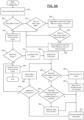
- control begins at 804 upon power-on of the microcontroller.
- the microcontroller loads boot code from internal flash into RAM and executes the boot code.
- the boot code may be stored in off-chip storage.
- Control executes the boot code and continues at 808.
- control determines whether new microcontroller code is present. If so, control transfers to 812; otherwise, control transfers to 816.
- New microcontroller code may have been programmed into the external flash via a serial connection to the microcontroller, which initiated a set of microcontroller flash programming instructions.
- the flash programming instructions perform flash programming to the external flash device.
- the serial connection to the microcontroller may be via the programmable logic device (PLD).
- the flash programming pins of the microcontroller may be connected to the external flash device via the PLD.
- the external flash may be large enough to accommodate two copies of the microcontroller code - the old microcontroller code and the new microcontroller code. In this way, if the new microcontroller code is loaded and has an error, the old microcontroller code will still be available.
- control checks whether the CRC (cyclic redundancy check) or other verification parameter is valid for the new code. If so, control transfers to 820; otherwise, control transfers to 816. At 820, control copies the new code from the external flash memory to internal flash storage. At 824, control determines whether the CRC or other verification measure is valid for the new code stored in internal flash. If so, control transfers to 816; otherwise, control transfers to 828.
- CRC cyclic redundancy check
- control copies the original (old) code from the external flash to internal flash.
- Control then continues at 816.
- control executes code from internal flash. While this process has been described in the context of the boot code loading new main microcontroller code, the reverse can also be performed, where the main microcontroller code verifies and then updates the boot code.
- the boot code is designed to be simple and concise to avoid the need to frequently update the boot code. In fact, in some implementations, updating the boot code may be disallowed.
- control determines whether new FPGA code is available. If so, control transfers to 844; otherwise, control transfers to 848. At 848, no new FPGA code is available and therefore control continues executing code from the internal flash storage. Once code execution is completed, such as upon a power down event, control ends.
- control loads the new FPGA code into memory.
- the new FPGA code may be stored in a reduced format compared to a standard SVF (serial vector format) file generally used by an in-circuit tester for programming a programmable logic device.
- SVF serial vector format
- the SVF file may include human-readable text, where data is repeated between instructions even when that data remains the same.
- significant compression may be achieved over the standard SVF file.
- an example SVF file is 503 kilobytes in size, while a compressed form is between 50 and 60 kilobytes, corresponding to between an 8:1 and a 10:1 reduction.
- the reduced form of the present disclosure is directly usable for programming the PLD.
- control can directly select the first instruction within the reduced form code without having to perform a decompression step.
- new code can be programmed into the FPGA while the FPGA is still operating under its previous programming.
- a final commit instruction or reset instruction then causes the FPGA to operate according to the new programming.
- Control continues at 856, where control determines whether the selected instruction includes data. If so, control transfers to 860; otherwise, control transfers to 864. At 860, control stores a pointer to the data.
- Control continues at 868, where control stores up to a predetermined unit of the data for the selected instruction.
- the predetermined unit may be 32 bits. Therefore, control stores up to 32 bits of the included data in the instruction. If the instruction includes more than 32 bits, the stored data may include only the beginning, the end, or the middle of the instructions data.
- control determines whether the selected instruction, which does not include data, requires data beyond the stored predetermined unit. If so, control transfers to 884; otherwise, control proceeds with 872.
- the selected instruction either does not require any data or requires only the data already stored within the predetermined unit. Meanwhile, at 884, control needs to retrieve additional data and therefore follows the pointer stored at 860. Control then continues at 872.
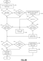
- control begins at 904 upon power-on of the microcontroller.
- the microcontroller loads boot code from internal flash into RAM and begins execution of the boot code.
- the boot code determines whether new main microcontroller code is present in the external flash memory array. If so, control transfers to 912; otherwise, control transfers to 816.
- control checks whether the CRC (cyclic redundancy check) or other verification parameter is valid for the new main code. If so, control transfers to 920; otherwise, control transfers to 916. At 920, control copies the new code from the external flash memory to internal flash storage. At 924, if a copy error occurred during the copy, control transfers to 928. Otherwise, control transfers to 932. At 932, control determines whether the CRC or other verification measure is valid for the code stored in internal flash. If so, control transfers to 936; otherwise, control transfers to 928. At 936, control erases the copied code from the external flash memory array so the boot code doesn't attempt to re-load the new code on the next boot. Control then continues at 940.
- CRC cyclic redundancy check
- control determines whether the CRC or other verification parameter is valid for the main code stored in the internal flash of the microcontroller. If so, control transfers to 940. Otherwise, control transfers to 928.
- control enters an indefinite freeze, awaiting the microcontroller to be reset. This reset may be performed manually by an operator interacting with the system in which the microcontroller is present, or may be performed automatically, such as by a watchdog timer.
- control determines whether new boot code is present in internal flash. For example, the main code of the microcontroller may write new boot code to internal flash. If new boot code is present in internal flash, control transfers to 944; otherwise, control transfers to 948. For example only, control may determine that new boot code is present by comparing a version number of the other boot code to the currently-executing boot code. Because of the relatively smaller size of the boot code, two copies of the boot code may reside in the internal flash at all times.
- the microcontroller may reset and attempt startup using the other set of boot code. For example, at the beginning of the boot code, the boot code may point the microcontroller to the alternate set of boot code, and upon successful operation of the boot code, before transferring to main code, the boot code may point the microcontroller back to the successfully-completing boot code.
- control determines whether the CRC of the new boot code is valid. If so, control transfers to 952. Otherwise, control transfers to 948.
- control updates a non-volatile indication of the microcontroller to start next time using the new boot code. For example, the microcontroller may have a non-volatile register pointing to a start address of the boot code. Control continues at 956, where the processor is reset. Control thereby ends upon processor reset.
- boot code transitions to execute main code from internal flash.
- Boot control depicted in FIG. 8B then ends.
- PLD updating such as is depicted in reference numerals 840-884 of FIG. 8A , may be a function of the main code.
- Control begins at 1004 upon power-on. If a display command is received, control transfers to 1008; otherwise, control transfers to 1012. At 1008, control retrieves data from the display command.
- control applies each bit of data to a respective output pin. For example, a grid of five rows and seven columns can be driven with twelve bits. Each time a twelve-bit data packet is received for the display, a new column can be selected based on the 7 column pins and between 0 and 5 LEDs in that column can be illuminated based on the five row pins. In various implementations, because the column selection is one-hot, a decoder can be used to turn a binary value into a bit field with a single binary one. Control then continues at 1012.
- the switch such as for a boost convertor in a PFC circuit, will be enabled and therefore any clamping is disabled.
- a clamp may prevent the control terminal (such as a gate) of the switch from moving to an enabled voltage.
- Control continues at 1020, where a timer is started.
- the switch is enabled.
- Control continues at 1028, where if a closed-loop reading of the switch state is on, control transfers to 1032; otherwise, control transfers 1036.
- control reports a fault and ends. Otherwise, control continues at 1028.
- the fault threshold may be based on a length of time in which the enabled switch should have been able to turn on. If the switch does not appear to have turned on, measurement of the switch may be faulty or the switch may be oscillating at a high frequency than the switch can maintain for an extended period of time. Therefore, the PFC may be shut down.
- Control continues at 1040, where control stores the timer value for later retrieval by the microcontroller.
- the microcontroller can send a read request to the PLD to retrieve the on delay.
- Control continues at 1044, where control remains until the PFC current (that is, the current through the inductor) exceeds a threshold. Once the PFC current exceeds the threshold, control transfer s to 1048, where control starts a timer from zero. At 1052, control disables the switch. At 1056, control enables the clamp, which drives the control terminal of the switch to the inactive state.
- PFC current that is, the current through the inductor
- control determines whether the switch state appears to be off. If so, control transfers to 1064; otherwise, control transfers 1068. At 1068, if the timer exceeds a fault threshold, control reports a fault and ends. Otherwise, control returns to 1060. At 1064, control stores the value of the timer, which now holds the length of time between disabling the switch and determining that the switch state is off. The microcontroller can retrieve this value.
- Control continues at 1072, where if a new off-time is received, control transfers to 1076; otherwise, control transfers to 1080.
- control determines whether the timer is greater than the stored off-time. If so, control transfers to 1084; otherwise, control remains in 1080.
- control determines whether the PFC current has fallen below the threshold. If so, control transfers to 1012, otherwise, control remains at 1084.
- the threshold in 1084 may be the same as the threshold in 1044; in other implementations, there may be some hysteresis.
- the tests in 1044 and 1084 may be implemented using a comparator.
- Spatial and functional relationships between elements are described using various terms, including “connected,” “engaged,” “coupled,” “adjacent,” “next to,” “on top of,” “above,” “below,” and “disposed.” Unless explicitly described as being “direct,” when a relationship between first and second elements is described in the above disclosure, that relationship can be a direct relationship where no other intervening elements are present between the first and second elements, but can also be an indirect relationship where one or more intervening elements are present (either spatially or functionally) between the first and second elements.
- the phrase at least one of A, B, and C should be construed to mean a logical (A OR B OR C), using a non-exclusive logical OR, and should not be construed to mean "at least one of A, at least one of B, and at least one of C.”
- the direction of an arrow generally demonstrates the flow of information (such as data or instructions) that is of interest to the illustration.
- information such as data or instructions
- the arrow may point from element A to element B. This unidirectional arrow does not imply that no other information is transmitted from element B to element A.
- element B may send requests for, or receipt acknowledgements of, the information to element A.
- module or the term “controller” may be replaced with the term “circuit.”
- the term “module” may refer to, be part of, or include: an Application Specific Integrated Circuit (ASIC); a digital, analog, or mixed analog/digital discrete circuit; a digital, analog, or mixed analog/digital integrated circuit; a combinational logic circuit; a field programmable gate array (FPGA); a processor circuit (shared, dedicated, or group) that executes code; a memory circuit (shared, dedicated, or group) that stores code executed by the processor circuit; other suitable hardware components that provide the described functionality; or a combination of some or all of the above, such as in a system-on-chip.
- ASIC Application Specific Integrated Circuit
- FPGA field programmable gate array
- the module may include one or more interface circuits.
- the interface circuits may include wired or wireless interfaces that are connected to a local area network (LAN), the Internet, a wide area network (WAN), or combinations thereof.
- LAN local area network
- WAN wide area network
- the functionality of any given module of the present disclosure may be distributed among multiple modules that are connected via interface circuits. For example, multiple modules may allow load balancing.
- a server (also known as remote, or cloud) module may accomplish some functionality on behalf of a client module.
- Some or all hardware features of a module may be defined using a language for hardware description, such as IEEE Standard 1364-2005 (commonly called “Verilog”) and IEEE Standard 1076-2008 (commonly called “VHDL”).
- the hardware description language may be used to manufacture and/or program a hardware circuit.
- some or all features of a module may be defined by a language, such as IEEE 1666-2005 (commonly called “SystemC”), that encompasses both code, as described below, and hardware description.
- code may include software, firmware, and/or microcode, and may refer to programs, routines, functions, classes, data structures, and/or objects.
- shared processor circuit encompasses a single processor circuit that executes some or all code from multiple modules.
- group processor circuit encompasses a processor circuit that, in combination with additional processor circuits, executes some or all code from one or more modules. References to multiple processor circuits encompass multiple processor circuits on discrete dies, multiple processor circuits on a single die, multiple cores of a single processor circuit, multiple threads of a single processor circuit, or a combination of the above.
- shared memory circuit encompasses a single memory circuit that stores some or all code from multiple modules.
- group memory circuit encompasses a memory circuit that, in combination with additional memories, stores some or all code from one or more modules.
- the term memory circuit is a subset of the term computer-readable medium.
- the term computer-readable medium does not encompass transitory electrical or electromagnetic signals propagating through a medium (such as on a carrier wave); the term computer-readable medium may therefore be considered tangible and non-transitory.
- Nonlimiting examples of a non-transitory computer-readable medium are nonvolatile memory circuits (such as a flash memory circuit, an erasable programmable read-only memory circuit, or a mask read-only memory circuit), volatile memory circuits (such as a static random access memory circuit or a dynamic random access memory circuit), magnetic storage media (such as an analog or digital magnetic tape or a hard disk drive), and optical storage media (such as a CD, a DVD, or a Blu-ray Disc).
- nonvolatile memory circuits such as a flash memory circuit, an erasable programmable read-only memory circuit, or a mask read-only memory circuit
- volatile memory circuits such as a static random access memory circuit or a dynamic random access memory circuit
- magnetic storage media such as an analog or digital magnetic tape or a hard disk drive
- optical storage media such as a CD, a DVD, or a Blu-ray Disc
- the apparatuses and methods described in this application may be partially or fully implemented by a special purpose computer created by configuring a general purpose computer to execute one or more particular functions embodied in computer programs.
- the functional blocks and flowchart elements described above serve as software specifications, which can be translated into the computer programs by the routine work of a skilled technician or programmer.
- the computer programs include processor-executable instructions that are stored on at least one non-transitory computer-readable medium.
- the computer programs may also include or rely on stored data.
- the computer programs may encompass a basic input/output system (BIOS) that interacts with hardware of the special purpose computer, device drivers that interact with particular devices of the special purpose computer, one or more operating systems, user applications, background services, background applications, etc.
- BIOS basic input/output system
- the computer programs may include: (i) descriptive text to be parsed, such as HTML (hypertext markup language), XML (extensible markup language), or JSON (JavaScript Object Notation), (ii) assembly code, (iii) object code generated from source code by a compiler, (iv) source code for execution by an interpreter, (v) source code for compilation and execution by a just-in-time compiler, etc.
- source code may be written using syntax from languages including C, C++, C#, Objective-C, Swift, Haskell, Go, SQL, R, Lisp, Java ® , Fortran, Perl, Pascal, Curl, OCaml, Javascript ® , HTML5 (Hypertext Markup Language 5th revision), Ada, ASP (Active Server Pages), PHP (PHP: Hypertext Preprocessor), Scala, Eiffel, Smalltalk, Erlang, Ruby, Flash ® , Visual Basic ® , Lua, MATLAB, SIMULINK, and Python ® .
- languages including C, C++, C#, Objective-C, Swift, Haskell, Go, SQL, R, Lisp, Java ® , Fortran, Perl, Pascal, Curl, OCaml, Javascript ® , HTML5 (Hypertext Markup Language 5th revision), Ada, ASP (Active Server Pages), PHP (PHP: Hypertext Preprocessor), Scala, Eiffel, Smalltalk, Erlang, Ruby, Flash
Landscapes
- Engineering & Computer Science (AREA)
- Theoretical Computer Science (AREA)
- General Engineering & Computer Science (AREA)
- Physics & Mathematics (AREA)
- General Physics & Mathematics (AREA)
- Power Engineering (AREA)
- Software Systems (AREA)
- Computer Hardware Design (AREA)
- Mathematical Physics (AREA)
- Computer Security & Cryptography (AREA)
- Computing Systems (AREA)
- Dc-Dc Converters (AREA)
- Control Of Ac Motors In General (AREA)
- Inverter Devices (AREA)
- Control Of Electric Motors In General (AREA)
Claims (15)
- Circuit (500) pour entraîner un moteur d'un compresseur, le circuit comprenant :
un microcontrôleur (504) comprenant un amplificateur opérationnel (604), un comparateur (616), une première interface série et une première broche dédiée, dans lequel :l'amplificateur opérationnel (604) est configuré pour amplifier une valeur représentative d'un courant dans un convertisseur de correction du facteur de puissance (PFC) configuré pour convertir le courant alternatif entrant en courant continu pour alimenter un circuit de puissance d'inverseur (232) configuré pour entraîner le moteur de compresseur (236) ;le comparateur est configuré pour comparer la valeur amplifiée à une valeur de référence et appliquer un signal de comparaison en réponse à la valeur amplifiée dépassant la valeur de référence ; etle signal de comparaison est émis sur la première broche dédiée ; etun dispositif logique programmable (508) comprenant :une deuxième interface série en communication avec la première interface série, dans lequel la deuxième interface série est configurée pour recevoir des messages de commande du microcontrôleur (504) ;une deuxième broche dédiée, dans lequel le signal de comparaison est reçu sur la deuxième broche dédiée ;un registre de temps d'arrêt (704), dans lequel, en réponse à la réception d'un premier message de commande du microcontrôleur (504), une valeur est définie dans le registre de temps d'arrêt (704) sur la base des données dans le premier message de commande ;une commande de commutateur (712) configurée pour générer un signal de commande pour commander un commutateur de puissance (320, 358) du convertisseur PFC ;un compteur (708) ; etun deuxième comparateur (728) configuré pour surveiller la valeur du compteur (708) par rapport à une valeur de retard excessif (732) ;dans lequel le dispositif logique programmable (508) est configuré pour :commander le commutateur d'alimentation du convertisseur PFC pour qu'il s'éteigne, et réinitialiser le compteur (708) en réponse à l'assertion du signal de comparaison ;à la suite de la commande du commutateur d'alimentation pour s'éteindre, attendre que le compteur (708) dépasse la valeur définie dans le registre de temps d'arrêt (704) puis commander le commutateur d'alimentation pour s'allumer ;mesurer un retard d'activation du commutateur d'alimentation et enregistrer la valeur du compteur en tant que retard d'activation, le retard d'activation étant un retard entre le moment où un commutateur est commandé pour s'activer et le moment où la tension aux bornes du commutateur reflète que le commutateur s'est allumé ;répéter la commande, l'attente et la mesure ; etdéclarer un défaut si le compteur (708) dépasse la valeur de retard excessif (732). - Circuit (500) selon la revendication 1, dans lequel le dispositif logique programmable (508) est configuré pour, en réponse à la réception d'un deuxième message de commande du microcontrôleur (504), transmettre le retard d'activation mesuré au microcontrôleur (504) ; éventuellement dans lequel le dispositif logique programmable (508) est configuré pour mesurer un retard de désactivation du commutateur d'alimentation.
- Circuit (500) selon la revendication 2, dans lequel le dispositif logique programmable (508) est configuré pour, en réponse à la réception d'un troisième message de commande du microcontrôleur (508), transmettre le retard de désactivation mesuré au microcontrôleur (508).
- Circuit (500) selon la revendication 1, comprenant en outre un deuxième comparateur configuré pour comparer un signal lié à une tension aux bornes du commutateur de puissance à un seuil, dans lequel le dispositif logique programmable (508) est configuré pour mesurer le retard d'activation du commutateur d'alimentation comme retard entre la commande du commutateur d'alimentation pour s'allumer et la réception d'une sortie du deuxième comparateur.
- Circuit (500) selon la revendication 1, dans lequel le dispositif logique programmable (508) est configuré pour :recevoir un deuxième message de commande comprenant une pluralité de bits ; etentraîner les valeurs de la pluralité de bits sur une pluralité de broches qui correspondent un à un à la pluralité de bits.
- Circuit (500) selon la revendication 1, dans lequel le microcontrôleur (504) est configuré pour :recevoir un nouveau micrologiciel via un port série connecté au microcontrôleur (504) via le dispositif logique programmable (508) ; etécrire le nouveau micrologiciel dans la mémoire flash qui est connectée au microcontrôleur (504) via le dispositif logique programmable (508).
- Circuit (500) selon la revendication 1, dans lequel le microcontrôleur (504) est configuré pour programmer le dispositif logique programmable (508) en utilisant un fichier de programmation codé dans un format de fichier compressé, dans lequel le format de fichier compressé comprend des instructions sérialisées que le microcontrôleur (504) peut s'exécuter sans effectuer d'opération de décompression sur le fichier de programmation.
- Circuit (500) selon la revendication 1, dans lequel le dispositif logique programmable (508) comprend des première et deuxième broches de sortie, et dans lequel le dispositif logique programmable (508) est configuré pour basculer les première et deuxième broches de sortie pour exciter une alimentation électrique isolée.
- Circuit selon la revendication 1, dans lequel le dispositif logique programmable (508) est configuré pour connecter directement des broches de programmation flash du microcontrôleur (504) à des broches de programmation flash d'une puce de mémoire flash externe.
- Procédé de fonctionnement d'un dispositif logique programmable (508), le procédé comprenant :l'incrémentation d'une valeur dans un compteur (708) ;la comparaison de la valeur à une valeur prédéterminée dans un registre de temps d'arrêt du dispositif logique programmable (508), dans lequel la valeur prédéterminée est indicative d'un temps d'arrêt souhaité d'un dispositif de commutation discret (320, 358) d'un convertisseur de correction de facteur de puissance (PFC) ;lorsque la valeur dépasse la valeur prédéterminée, la génération d'un signal de commande qui provoque l'excitation du dispositif de commutation discret ;la réception d'un signal d'état de commutation qui indique si le dispositif de commutation discret est alimenté ;en réponse à une transition dans le signal d'état de commutation indiquant que le dispositif de commutation discret a été excité, l'enregistrement de la valeur du compteur comme un retard d'activation ; etle stockage du retard d'activation ;en réponse à la réception d'un signal de comparaison, la réinitialisation de la valeur dans le compteur (704) et la commande de l'arrêt du dispositif de commutation discret, dans lequel le signal de comparaison indique qu'une valeur de courant mesurée correspondant au dispositif de commutation discret a dépassé une valeur de courant de référence ;la mise à jour de la valeur prédéterminée dans le registre de temps d'arrêt selon une commande reçue par le dispositif logique programmable (508) ;la surveillance de la valeur du compteur (708) par rapport à une valeur de retard excessif (732), et la déclaration d'un défaut si le compteur (708) dépasse la valeur de retard excessif (732) ;dans lequel le signal de comparaison est reçu par une deuxième broche dédiée du dispositif logique programmable (508) et la commande est reçue par une deuxième interface série du dispositif logique programmable (508).
- Procédé selon la revendication 10, comprenant en outre l'arrêt de la génération du signal de commande de verrouillage pendant que le signal de commande est généré, dans lequel le signal de commande de verrouillage empêche le dispositif de commutation discret d'être excité.
- Procédé selon la revendication 10, comprenant en outre la notification du retard d'activation à un contrôleur externe au dispositif logique programmable (508).
- Procédé selon la revendication 12, comprenant en outre :la réception d'une demande de retard au niveau du dispositif logique programmable (508) sur un bus série ; etla transmission du retard d'activation à une source de la demande de retard sur le bus série.
- Procédé selon la revendication 10, comprenant en outre :la réception d'un signal d'état de commutation qui indique si le dispositif de commutation discret est excité ; et
soitla comparaison de la valeur du compteur à un retard d'activation acceptable ; eten réponse à la valeur du compteur dépassant le retard d'activation acceptable alors que le signal d'état de commutateur indique que le dispositif de commutation discret n'est pas excité, la génération d'un signal de défaut ;le procédé comprenant éventuellement en outre l'arrêt de la génération du signal de commande en réponse à la génération du signal de défaut ; ouen réponse à une transition dans le signal d'état de commutation indiquant que le dispositif de commutation discret a été désexcité, l'enregistrement de la valeur du compteur en tant que retard de désactivation ; etl'enregistrement du retard de désactivation. - Dispositif logique programmable (508) programmé pour mettre en oeuvre le procédé de la revendication 10.
Applications Claiming Priority (26)
| Application Number | Priority Date | Filing Date | Title |
|---|---|---|---|
| US201662323498P | 2016-04-15 | 2016-04-15 | |
| US201662323607P | 2016-04-15 | 2016-04-15 | |
| US201662323563P | 2016-04-15 | 2016-04-15 | |
| US201662323519P | 2016-04-15 | 2016-04-15 | |
| US201662323505P | 2016-04-15 | 2016-04-15 | |
| US201662323532P | 2016-04-15 | 2016-04-15 | |
| US201662323538P | 2016-04-15 | 2016-04-15 | |
| US201662323527P | 2016-04-15 | 2016-04-15 | |
| US201662323517P | 2016-04-15 | 2016-04-15 | |
| US201662323588P | 2016-04-15 | 2016-04-15 | |
| US201662398658P | 2016-09-23 | 2016-09-23 | |
| US201662398641P | 2016-09-23 | 2016-09-23 | |
| US201662398668P | 2016-09-23 | 2016-09-23 | |
| US15/419,464 US10277115B2 (en) | 2016-04-15 | 2017-01-30 | Filtering systems and methods for voltage control |
| US15/419,349 US10656026B2 (en) | 2016-04-15 | 2017-01-30 | Temperature sensing circuit for transmitting data across isolation barrier |
| US15/419,423 US10763740B2 (en) | 2016-04-15 | 2017-01-30 | Switch off time control systems and methods |
| US15/419,394 US10305373B2 (en) | 2016-04-15 | 2017-01-30 | Input reference signal generation systems and methods |
| US15/430,978 US9965928B2 (en) | 2016-04-15 | 2017-02-13 | System and method for displaying messages in a column-by-column format via an array of LEDs connected to a circuit of a compressor |
| US15/487,426 US9933842B2 (en) | 2016-04-15 | 2017-04-13 | Microcontroller architecture for power factor correction converter |
| US15/487,226 US11387729B2 (en) | 2016-04-15 | 2017-04-13 | Buck-converter-based drive circuits for driving motors of compressors and condenser fans |
| US15/487,101 US10320322B2 (en) | 2016-04-15 | 2017-04-13 | Switch actuation measurement circuit for voltage converter |
| US15/487,175 US10770966B2 (en) | 2016-04-15 | 2017-04-13 | Power factor correction circuit and method including dual bridge rectifiers |
| US15/487,151 US10312798B2 (en) | 2016-04-15 | 2017-04-13 | Power factor correction circuits and methods including partial power factor correction operation for boost and buck power converters |
| US15/487,201 US10075065B2 (en) | 2016-04-15 | 2017-04-13 | Choke and EMI filter circuits for power factor correction circuits |
| US15/487,027 US10284132B2 (en) | 2016-04-15 | 2017-04-13 | Driver for high-frequency switching voltage converters |
| PCT/US2017/027691 WO2017181055A1 (fr) | 2016-04-15 | 2017-04-14 | Architecture de micro-dispositif de commande pour un convertisseur de correction de facteur de puissance |
Publications (3)
| Publication Number | Publication Date |
|---|---|
| EP3443653A1 EP3443653A1 (fr) | 2019-02-20 |
| EP3443653A4 EP3443653A4 (fr) | 2019-12-25 |
| EP3443653B1 true EP3443653B1 (fr) | 2023-05-31 |
Family
ID=60038832
Family Applications (1)
| Application Number | Title | Priority Date | Filing Date |
|---|---|---|---|
| EP17783267.2A Active EP3443653B1 (fr) | 2016-04-15 | 2017-04-14 | Architecture de microcontroleur de commande pour un convertisseur de correction de facteur de puissance |
Country Status (5)
| Country | Link |
|---|---|
| US (3) | US9933842B2 (fr) |
| EP (1) | EP3443653B1 (fr) |
| CN (1) | CN109155583B (fr) |
| MX (1) | MX2018012625A (fr) |
| WO (1) | WO2017181055A1 (fr) |
Families Citing this family (27)
| Publication number | Priority date | Publication date | Assignee | Title |
|---|---|---|---|---|
| US10277115B2 (en) | 2016-04-15 | 2019-04-30 | Emerson Climate Technologies, Inc. | Filtering systems and methods for voltage control |
| US10075065B2 (en) | 2016-04-15 | 2018-09-11 | Emerson Climate Technologies, Inc. | Choke and EMI filter circuits for power factor correction circuits |
| US9933842B2 (en) | 2016-04-15 | 2018-04-03 | Emerson Climate Technologies, Inc. | Microcontroller architecture for power factor correction converter |
| US10305373B2 (en) | 2016-04-15 | 2019-05-28 | Emerson Climate Technologies, Inc. | Input reference signal generation systems and methods |
| US9965928B2 (en) | 2016-04-15 | 2018-05-08 | Emerson Climate Technologies, Inc. | System and method for displaying messages in a column-by-column format via an array of LEDs connected to a circuit of a compressor |
| US10284132B2 (en) | 2016-04-15 | 2019-05-07 | Emerson Climate Technologies, Inc. | Driver for high-frequency switching voltage converters |
| US10312798B2 (en) | 2016-04-15 | 2019-06-04 | Emerson Electric Co. | Power factor correction circuits and methods including partial power factor correction operation for boost and buck power converters |
| US10763740B2 (en) | 2016-04-15 | 2020-09-01 | Emerson Climate Technologies, Inc. | Switch off time control systems and methods |
| US10656026B2 (en) | 2016-04-15 | 2020-05-19 | Emerson Climate Technologies, Inc. | Temperature sensing circuit for transmitting data across isolation barrier |
| CN107769640B (zh) * | 2017-10-30 | 2024-02-06 | 深圳市复兴伟业技术有限公司 | 一种直流有刷电机堵转检测及正反转驱动电路 |
| DE102017220098A1 (de) * | 2017-11-10 | 2019-05-16 | Robert Bosch Gmbh | Stromrichtervorrichtung, elektrisches Antriebssystem und Verfahren zum Betreiben einer elektrischen Maschine |
| US10343879B1 (en) * | 2018-01-05 | 2019-07-09 | MotoAlliance | Three speed electronic winch contactor |
| JP7154019B2 (ja) * | 2018-03-08 | 2022-10-17 | ナブテスコ株式会社 | Ac-ac電力変換装置 |
| EP3618213A1 (fr) | 2018-07-23 | 2020-03-04 | Hoffman Enclosures, Inc. | Unité de commande électronique triphasé pour climatiseurs d'enceinte |
| CN111726052B (zh) * | 2019-03-20 | 2024-06-25 | 广东美的制冷设备有限公司 | 驱动控制电路和空调器 |
| CN109870921B (zh) * | 2019-03-26 | 2022-04-01 | 广东美的制冷设备有限公司 | 驱动控制电路与家电设备 |
| US11601051B2 (en) * | 2019-06-18 | 2023-03-07 | Qualcomm Incorporated | Connection terminal pattern and layout for three-level buck regulator |
| US11362582B2 (en) * | 2019-07-26 | 2022-06-14 | Emerson Climate Technologies, Inc. | Multi-phase converter control system and method for interleaving multi-phase converters |
| US11016755B2 (en) * | 2019-07-31 | 2021-05-25 | Dell Products L.P. | System and method to secure embedded controller flashing process |
| TWI709839B (zh) * | 2019-09-09 | 2020-11-11 | 海韻電子工業股份有限公司 | 功因校正電路的校正控制模組 |
| US11566630B2 (en) * | 2020-05-13 | 2023-01-31 | Nidec Motor Corporation | Motor control system providing single output signal and high number of speed settings |
| CN114033689B (zh) * | 2021-10-27 | 2023-12-22 | 宁波德曼压缩机有限公司 | 一种变频螺杆空压机空滤堵塞程度的判断方法、系统、智能终端和介质 |
| TWI771233B (zh) * | 2021-11-24 | 2022-07-11 | 佳必琪國際股份有限公司 | 電路元件保護裝置及其方法 |
| US12122251B2 (en) * | 2022-09-28 | 2024-10-22 | BorgWarner US Technologies LLC | Systems and methods for bidirectional message architecture for inverter for electric vehicle |
| TWI862286B (zh) * | 2023-11-17 | 2024-11-11 | 亞源科技股份有限公司 | 多輸入電源系統 |
| US12584450B2 (en) * | 2024-06-04 | 2026-03-24 | Rv Mobile Power, Llc | Pre-excitation of genset based on one or more trigger signals |
| CN118739863B (zh) * | 2024-09-03 | 2024-11-19 | 秦皇岛市桑格电气控制设备有限公司 | 环保用双芯片控制的高频软稳电源、自适应方法及除尘器 |
Citations (1)
| Publication number | Priority date | Publication date | Assignee | Title |
|---|---|---|---|---|
| US5933344A (en) * | 1995-03-20 | 1999-08-03 | Hitachi, Ltd. | Microprocessor having timer circuit generating complementary non-overlapped PWM signals |
Family Cites Families (438)
| Publication number | Priority date | Publication date | Assignee | Title |
|---|---|---|---|---|
| US4388578A (en) * | 1980-07-07 | 1983-06-14 | Cynex Manufacturing Corporation | Power factor controller |
| US4437146A (en) | 1982-08-09 | 1984-03-13 | Pacific Electro Dynamics, Inc. | Boost power supply having power factor correction circuit |
| US4504922A (en) | 1982-10-28 | 1985-03-12 | At&T Bell Laboratories | Condition sensor |
| US4959606A (en) | 1989-01-06 | 1990-09-25 | Uniphase Corporation | Current mode switching regulator with programmed offtime |
| US4939473A (en) | 1989-03-20 | 1990-07-03 | The United States Of America As Represented By The Secretary Of The Navy | Tracking harmonic notch filter |
| CN1017748B (zh) | 1989-11-16 | 1992-08-05 | 清华大学 | 比较法热敏电阻测温变送器 |
| US5410360A (en) | 1991-06-14 | 1995-04-25 | Wavephore, Inc. | Timing control for injecting a burst and data into a video signal |
| US5367617A (en) | 1992-07-02 | 1994-11-22 | Microsoft Corporation | System and method of hybrid forward differencing to render Bezier splines |
| US5594635A (en) | 1993-03-30 | 1997-01-14 | Motorola, Inc. | Constant frequency, zero-voltage-switching converters with resonant switching bridge |
| US6188203B1 (en) | 1996-11-01 | 2001-02-13 | Lucas Aerospace Power Equipment Corporation | Ground fault detection circuit |
| US5583420A (en) | 1993-10-01 | 1996-12-10 | Lucas Aerospace Power Equipment Corporation | Microprocessor controller for starter/generator |
| US5493101A (en) | 1993-12-15 | 1996-02-20 | Eaton Corporation | Positive temperature coefficient transition sensor |
| US5506484A (en) | 1994-06-10 | 1996-04-09 | Westinghouse Electric Corp. | Digital pulse width modulator with integrated test and control |
| US6018200A (en) | 1994-09-14 | 2000-01-25 | Coleman Powermate, Inc. | Load demand throttle control for portable generator and other applications |
| ES2150072T3 (es) | 1995-05-26 | 2000-11-16 | At & T Corp | Control del factor de potencia en rectificadores conmutados. |
| US5600233A (en) | 1995-08-22 | 1997-02-04 | Chicago Stage Equipment Co. | Electronic power control circuit |
| US5754036A (en) | 1996-07-25 | 1998-05-19 | Lti International, Inc. | Energy saving power control system and method |
| US6115051A (en) | 1996-08-07 | 2000-09-05 | Adobe Systems Incorporated | Arc-length reparameterization |
| US5823004A (en) | 1996-11-12 | 1998-10-20 | American Standard Inc. | Outdoor fan control for part load efficiency |
| EP0992179B1 (fr) | 1997-06-16 | 2002-12-11 | Lightech Electronics Industries Ltd. | Alimentation electrique pour un systeme d'eclairage hybride |
| US6307759B1 (en) | 1997-10-31 | 2001-10-23 | Hitachi, Ltd. | Control device for electric power translating device |
| JP3328572B2 (ja) | 1998-02-23 | 2002-09-24 | リンナイ株式会社 | スイッチ状態検出装置 |
| EP0942271A1 (fr) | 1998-03-10 | 1999-09-15 | Oxford Instruments (Uk) Limited | Améliorations dans la thermométrie par résistance |
| EP0955721A1 (fr) | 1998-05-05 | 1999-11-10 | STMicroelectronics S.r.l. | Méthode de commande par MLI d'un moteur sans balais avec profils de tension mémorisés numériquement et pertes réduites |
| US6042580A (en) | 1998-05-05 | 2000-03-28 | Cardiac Pacemakers, Inc. | Electrode having composition-matched, common-lead thermocouple wire for providing multiple temperature-sensitive junctions |
| US6281658B1 (en) | 1999-01-08 | 2001-08-28 | Lg Electronics Inc. | Power factor compensation device for motor driving inverter system |
| US6031749A (en) | 1999-03-31 | 2000-02-29 | Vari-Lite, Inc. | Universal power module |
| US6169670B1 (en) | 1999-04-08 | 2001-01-02 | Hitachi, Ltd. | Inverter apparatus operatable over extended frequency range while suppressing output error |
| US6313602B1 (en) | 1999-04-30 | 2001-11-06 | Texas Instruments Incorporated | Modified space vector pulse width modulation technique to reduce DC bus ripple effect in voltage source inverters |
| JP3589086B2 (ja) | 1999-05-17 | 2004-11-17 | 松下電器産業株式会社 | 電源装置 |
| JP4618897B2 (ja) | 1999-05-21 | 2011-01-26 | エーベーエム−パプスト ザンクト ゲオルゲン ゲーエムベーハー ウント コー.カーゲー | 電気モータの少なくとも1つの駆動データ値を不揮発性に記憶するための方法、およびこの方法を実施するための電気モータ |
| US6239523B1 (en) | 1999-07-01 | 2001-05-29 | General Electric Company | Cutout start switch |
| US6249104B1 (en) | 1999-07-01 | 2001-06-19 | General Electric Company | Cutout start switch heating |
| JP2001147243A (ja) | 1999-11-24 | 2001-05-29 | Mitsubishi Electric Corp | アナログ信号検出回路及び半導体電力変換装置の交流側電流検出器 |
| US6433504B1 (en) | 1999-12-13 | 2002-08-13 | A. O. Smith Corporation | Method and apparatus of improving the efficiency of an induction motor |
| JP3584847B2 (ja) | 2000-04-03 | 2004-11-04 | ダイキン工業株式会社 | 空気調和機 |
| JP2001289549A (ja) | 2000-04-05 | 2001-10-19 | Hitachi Ltd | 冷蔵庫制御装置 |
| US6295215B1 (en) | 2000-04-06 | 2001-09-25 | Powerware Corporation | AC power supply apparatus with economy mode and methods of operation thereof |
| US6483265B1 (en) | 2000-05-23 | 2002-11-19 | General Electric Company | Methods and systems for minimizing vibration in electric machines |
| US6282910B1 (en) | 2000-06-21 | 2001-09-04 | American Standard International Inc. | Indoor blower variable speed drive for reduced airflow |
| US6384579B2 (en) | 2000-06-27 | 2002-05-07 | Origin Electric Company, Limited | Capacitor charging method and charging apparatus |
| US6498451B1 (en) | 2000-09-06 | 2002-12-24 | Delphi Technologies, Inc. | Torque ripple free electric power steering |
| JP4318015B2 (ja) | 2000-12-11 | 2009-08-19 | ソニー株式会社 | 光ディスク再生装置、光ディスク記録再生装置およびレーザノイズキャンセル回路 |
| US6593881B2 (en) | 2000-12-12 | 2003-07-15 | Harris Corporation | Phased array antenna including an antenna module temperature sensor and related methods |
| JP4001551B2 (ja) | 2000-12-12 | 2007-10-31 | ミニ−ミッター カンパニー,インコーポレイテッド | 温度計及び温度計の製造方法 |
| GB0105502D0 (en) | 2001-03-06 | 2001-04-25 | Switched Reluctance Drives Ltd | Compensation for variable voltage |
| US6892546B2 (en) | 2001-05-03 | 2005-05-17 | Emerson Retail Services, Inc. | System for remote refrigeration monitoring and diagnostics |
| DE10123789A1 (de) | 2001-05-16 | 2002-11-21 | Philips Corp Intellectual Pty | Stromversorgungssystem |
| JP3699663B2 (ja) | 2001-05-24 | 2005-09-28 | 勲 高橋 | インバータ制御方法およびその装置 |
| US6693407B2 (en) | 2001-06-26 | 2004-02-17 | The Boeing Company | Controller and associated system and method for pulse-width-modulation switching noise reduction by voltage control |
| EP2267859A3 (fr) | 2001-07-23 | 2014-08-13 | Northern Power Systems Utility Scale, Inc. | Système de commande pour convertisseur de puissance et procédé de contrôle du fonctionnement d'un convertisseur de puissance |
| DE50212540D1 (de) | 2001-08-01 | 2008-09-04 | Ebm Papst St Georgen Gmbh & Co | Ür die zeitliche dauer eines sich periodisch wiederholenden impulsförmigen signals, und vorrichtung zur durchführung eines solchen verfahrens |
| US7336514B2 (en) | 2001-08-10 | 2008-02-26 | Micropulse Technologies | Electrical power conservation apparatus and method |
| US6476663B1 (en) | 2001-08-14 | 2002-11-05 | Sun Microsystems, Inc. | Method for reducing supply noise near an on-die thermal sensor |
| US6900607B2 (en) | 2001-08-17 | 2005-05-31 | Delphi Technologies, Inc. | Combined feedforward and feedback parameter estimation for electric machines |
| JP4367130B2 (ja) | 2001-09-29 | 2009-11-18 | ダイキン工業株式会社 | 相電流検出方法、インバータ制御方法、モータ制御方法およびこれらの装置 |
| JP4236402B2 (ja) | 2001-10-09 | 2009-03-11 | 富士通マイクロエレクトロニクス株式会社 | 半導体装置 |
| JP3825678B2 (ja) | 2001-10-30 | 2006-09-27 | 三洋電機株式会社 | 圧縮機の制御装置 |
| DE10156216A1 (de) | 2001-11-15 | 2003-06-05 | Siemens Ag | Verfahren zur Minderung des Einflusses eines Gleichstromanteils im Laststrom eines Asynchronmotors |
| AU2002350428A1 (en) | 2001-11-23 | 2003-06-10 | Danfoss Drives A/S | Frequency converter for different mains voltages |
| DE10206191B4 (de) | 2001-11-27 | 2006-02-02 | Siemens Ag | Verfahren zur feldorientierten Regelung einer permanenterregten Synchronmaschine mit Reluktanzmoment |
| DE10257578A1 (de) | 2001-12-21 | 2003-07-03 | Fuji Electric Co Ltd | Schaltnetzteil |
| US6975098B2 (en) | 2002-01-31 | 2005-12-13 | Vlt, Inc. | Factorized power architecture with point of load sine amplitude converters |
| US6710573B2 (en) | 2002-03-06 | 2004-03-23 | Andrew S. Kadah | Method of controlling pulsed AC power |
| US6735968B2 (en) | 2002-03-29 | 2004-05-18 | Hitachi, Ltd. | Refrigerating apparatus and an inverter device used therein |
| US6650092B1 (en) | 2002-05-24 | 2003-11-18 | Motorola, Inc. | System and method for regulating a power system with feedback using current sensing |
| GB0213098D0 (en) | 2002-06-07 | 2002-07-17 | Trw Ltd | Motor control device |
| ES2197822B1 (es) | 2002-06-18 | 2005-09-16 | Fagor, S. Coop. | Dispositivo electronico para el control de un motor sincrono con rotor de iman permanente. |
| US6556462B1 (en) | 2002-06-28 | 2003-04-29 | General Electric Company | High power factor converter with a boost circuit having continuous/discontinuous modes |
| US7061195B2 (en) | 2002-07-25 | 2006-06-13 | International Rectifier Corporation | Global closed loop control system with dv/dt control and EMI/switching loss reduction |
| US7164590B2 (en) | 2002-07-29 | 2007-01-16 | International Rectifier Corporation | Power transfer system with reduced component ratings |
| US6737833B2 (en) | 2002-07-31 | 2004-05-18 | Honeywell International Inc. | Voltage control of an HR-PMG without a rotor position sensor |
| KR20040025420A (ko) | 2002-09-19 | 2004-03-24 | 삼성전자주식회사 | 냉장고의 자가진단시스템 및 그 제어방법 |
| US6979967B2 (en) | 2002-10-15 | 2005-12-27 | International Rectifier Corporation | Efficiency optimization control for permanent magnet motor drive |
| WO2004038900A2 (fr) | 2002-10-21 | 2004-05-06 | Advanced Power Technology, Inc. | Convertisseur de puissance, appareil a facteur de puissance en entree eleve et faible distorsion harmonique et procede afferent |
| US6906933B2 (en) | 2002-11-01 | 2005-06-14 | Powerware Corporation | Power supply apparatus and methods with power-factor correcting bypass mode |
| US7068016B2 (en) | 2002-11-01 | 2006-06-27 | International Rectifier Corporation | One cycle control PFC boost converter integrated circuit with inrush current limiting, fan motor speed control and housekeeping power supply controller |
| US6819011B2 (en) | 2002-11-14 | 2004-11-16 | Fyre Storm, Inc. | Switching power converter controller with watchdog timer |
| JP2004201487A (ja) | 2002-11-28 | 2004-07-15 | Nsk Ltd | モータ及びその駆動制御装置 |
| US6984948B2 (en) | 2002-12-12 | 2006-01-10 | Matsushita Electric Industrial Co., Ltd. | Motor control apparatus |
| GB2396441B (en) | 2002-12-20 | 2005-11-30 | Motorola Inc | Circuit and method for supplying an electrical a.c. load |
| JP4557616B2 (ja) | 2004-07-02 | 2010-10-06 | 株式会社日立産機システム | 電力変換装置 |
| US6902117B1 (en) | 2003-04-21 | 2005-06-07 | Howard Rosen | Wireless transmission of temperature determining signals to a programmable thermostat |
| CN100395954C (zh) | 2003-04-22 | 2008-06-18 | 松下电器产业株式会社 | 电动机控制装置、压缩机、空调机、和冷藏库 |
| CN100448158C (zh) | 2003-04-30 | 2008-12-31 | 松下电器产业株式会社 | 电动机驱动装置 |
| JP3878625B2 (ja) | 2003-06-20 | 2007-02-07 | 松下電器産業株式会社 | 振幅調整回路、モータ駆動制御装置、振幅調整方法、及びモータ駆動制御方法 |
| EP1501186B1 (fr) | 2003-07-18 | 2018-08-22 | III Holdings 10, LLC | Appareil de commande de moteur |
| AU2003903787A0 (en) | 2003-07-22 | 2003-08-07 | Sergio Adolfo Maiocchi | A system for operating a dc motor |
| CN100417004C (zh) | 2003-07-23 | 2008-09-03 | 松下电器产业株式会社 | 电动机控制设备及使用其的洗衣机和干燥机 |
| US7403400B2 (en) | 2003-07-24 | 2008-07-22 | Harman International Industries, Incorporated | Series interleaved boost converter power factor correcting power supply |
| US6949915B2 (en) | 2003-07-24 | 2005-09-27 | Harman International Industries, Incorporated | Opposed current converter power factor correcting power supply |
| CN100489419C (zh) | 2003-08-25 | 2009-05-20 | 计算机程序控制公司 | 制冷系统和方法 |
| US6952089B2 (en) | 2003-08-29 | 2005-10-04 | Rockwell Automation Technologies, Inc. | Motor drive with voltage-accurate inverter |
| US6859008B1 (en) | 2003-09-17 | 2005-02-22 | Rockwell Automation Technologies, Inc. | Method and apparatus for compensating for cable charging effects on control algorithms |
| US7636748B2 (en) | 2003-09-29 | 2009-12-22 | Microsoft Corporation | Display configurations for a data processing device |
| US7135830B2 (en) | 2003-09-30 | 2006-11-14 | Reliance Electric Technologies, Llc | System and method for identifying operational parameters of a motor |
| JP4477429B2 (ja) | 2003-11-05 | 2010-06-09 | 富士通マイクロエレクトロニクス株式会社 | 半導体集積回路 |
| KR100626444B1 (ko) | 2003-11-24 | 2006-09-20 | 엘지전자 주식회사 | 공기조화기의 실내기 |
| DE10356515A1 (de) | 2003-12-03 | 2005-07-14 | Siemens Ag | Antriebssystem |
| DK3589081T3 (da) | 2004-03-15 | 2024-03-18 | Signify North America Corp | Effektstyringfremgangsmåder og -apparat |
| US7425806B2 (en) | 2004-04-12 | 2008-09-16 | York International Corporation | System and method for controlling a variable speed drive |
| US7180273B2 (en) | 2004-06-07 | 2007-02-20 | International Rectifier Corporation | Low switching frequency power factor correction circuit |
| FI117409B (fi) | 2004-06-10 | 2006-09-29 | Abb Oy | Anturiresistanssin isoloitu mittauspiiri |
| US7148664B2 (en) | 2004-06-28 | 2006-12-12 | International Rectifier Corporation | High frequency partial boost power factor correction control circuit and method |
| US20060022648A1 (en) | 2004-08-02 | 2006-02-02 | Green Power Technologies Ltd. | Method and control circuitry for improved-performance switch-mode converters |
| JP3772898B2 (ja) | 2004-09-08 | 2006-05-10 | ダイキン工業株式会社 | 多相電流供給回路及び駆動装置 |
| KR100608692B1 (ko) | 2004-09-23 | 2006-08-09 | 엘지전자 주식회사 | 공기조화기의 팬모터 속도가변장치 |
| JP4475097B2 (ja) | 2004-11-02 | 2010-06-09 | オムロン株式会社 | スイッチの状態検出回路および自動車窓用開閉装置 |
| JP4760000B2 (ja) | 2004-12-09 | 2011-08-31 | ダイキン工業株式会社 | 多相電流供給回路、駆動装置、圧縮機、及び空気調和機 |
| US7723964B2 (en) | 2004-12-15 | 2010-05-25 | Fujitsu General Limited | Power supply device |
| US7466112B2 (en) | 2005-02-08 | 2008-12-16 | Linear Technology Corporation | Variable frequency current-mode control for switched step up-step down regulators |
| US8550368B2 (en) | 2005-02-23 | 2013-10-08 | Emerson Electric Co. | Interactive control system for an HVAC system |
| US7359224B2 (en) | 2005-04-28 | 2008-04-15 | International Rectifier Corporation | Digital implementation of power factor correction |
| US7456621B2 (en) | 2005-05-06 | 2008-11-25 | Silicon Laboratories Inc. | Digital controller based power factor correction circuit |
| US7208891B2 (en) | 2005-05-06 | 2007-04-24 | York International Corp. | Variable speed drive for a chiller system |
| US7202626B2 (en) | 2005-05-06 | 2007-04-10 | York International Corporation | Variable speed drive for a chiller system with a switched reluctance motor |
| US7193383B2 (en) | 2005-07-06 | 2007-03-20 | Honeywell International, Inc. | Enhanced floating reference frame controller for sensorless control of synchronous machines |
| US7495404B2 (en) | 2005-08-17 | 2009-02-24 | Honeywell International Inc. | Power factor control for floating frame controller for sensorless control of synchronous machines |
| US7573275B2 (en) | 2005-08-31 | 2009-08-11 | Ngk Spark Plug Co., Ltd. | Temperature sensor control apparatus |
| US7715698B2 (en) | 2005-08-31 | 2010-05-11 | Thor Power Corporation | Control electronics for brushless motors |
| US7413343B2 (en) | 2005-09-16 | 2008-08-19 | Kyocera Wireless Corp. | Apparatus for determining a temperature sensing element |
| US7256564B2 (en) | 2005-09-29 | 2007-08-14 | Agile Systems Inc. | System and method for attenuating noise associated with a back electromotive force signal in a motor |
| US7239257B1 (en) | 2005-10-03 | 2007-07-03 | Zilker Labs, Inc. | Hardware efficient digital control loop architecture for a power converter |
| US7309977B2 (en) | 2005-10-11 | 2007-12-18 | Active-Semi International, Inc. | System and method for an adaptive synchronous switch in switching regulators |
| EP1946014A4 (fr) | 2005-10-17 | 2012-04-25 | Carrier Corp | Systeme refrigerant a variateur de vitesse |
| EP1777530B1 (fr) | 2005-10-19 | 2008-11-26 | ABB Oy | Procédé et appareil pour mesurer des courants de sortie dans des circuits onduleurs |
| DE102005055832A1 (de) | 2005-11-23 | 2007-05-24 | Patent-Treuhand-Gesellschaft für elektrische Glühlampen mbH | Schaltungsanordnung und Verfahren zum Ansteuern eines elektronischen Bauelements mit einem Ausgangssignal eines Mikroprozessors |
| EP1977503B1 (fr) | 2005-12-12 | 2019-02-20 | Yaironit Ltd. | Appareil, procede et systeme pour la commande d'une conversion alternatif / alternatif |
| KR100764779B1 (ko) | 2006-03-14 | 2007-10-11 | 엘지전자 주식회사 | 직류 전원 공급 장치 |
| KR100823922B1 (ko) | 2006-03-14 | 2008-04-22 | 엘지전자 주식회사 | 직류 전원 공급 장치 및 그 방법 |
| JP4079178B2 (ja) | 2006-04-19 | 2008-04-23 | ダイキン工業株式会社 | 電力変換器及びその制御方法並びに空気調和機 |
| US20080000246A1 (en) | 2006-06-28 | 2008-01-03 | Computime, Ltd. | Conveying Temperature Information in a Controlled Variable Speed Heating, Ventilation, and Air Conditioning (HVAC) System |
| JP4956123B2 (ja) | 2006-09-28 | 2012-06-20 | 三洋電機株式会社 | モータ制御装置 |
| US7734379B2 (en) | 2006-10-23 | 2010-06-08 | Service Pro Monitoring, Llc | System, method, and apparatus for managing wastewater treatment installation |
| US7721564B2 (en) | 2006-11-21 | 2010-05-25 | B/E Aerospace, Inc. | Wild frequency avionic refrigeration system and controller therefor |
| US7902809B2 (en) | 2006-11-28 | 2011-03-08 | International Rectifier Corporation | DC/DC converter including a depletion mode power switch |
| US7667986B2 (en) | 2006-12-01 | 2010-02-23 | Flextronics International Usa, Inc. | Power system with power converters having an adaptive controller |
| US7675759B2 (en) | 2006-12-01 | 2010-03-09 | Flextronics International Usa, Inc. | Power system with power converters having an adaptive controller |
| US9197132B2 (en) | 2006-12-01 | 2015-11-24 | Flextronics International Usa, Inc. | Power converter with an adaptive controller and method of operating the same |
| ES2675185T3 (es) | 2007-01-09 | 2018-07-09 | Daikin Industries, Ltd. | Procedimiento de funcionamiento de compresor inversor y dispositivo de accionamiento de compresor |
| JP4320743B2 (ja) | 2007-03-02 | 2009-08-26 | 株式会社デンソー | 回転機の制御装置 |
| CA2677406A1 (fr) | 2007-03-20 | 2008-09-25 | Access Business Group International Llc | Alimentation |
| CN101647186B (zh) | 2007-04-27 | 2012-10-17 | 三菱电机株式会社 | 电力变换装置 |
| US7554473B2 (en) | 2007-05-02 | 2009-06-30 | Cirrus Logic, Inc. | Control system using a nonlinear delta-sigma modulator with nonlinear process modeling |
| GB0709200D0 (en) | 2007-05-12 | 2007-06-20 | Trw Ltd | Current measuring apparatus for use with electric motors |
| TW200847593A (en) * | 2007-05-18 | 2008-12-01 | Richtek Techohnology Corp | Digital voltage transformer and its control method |
| US7847507B2 (en) | 2007-05-31 | 2010-12-07 | General Electric Company | Zero-current notch waveform for control of a three-phase, wye-connected H-bridge converter for powering a high-speed electric motor |
| US8050063B2 (en) | 2007-05-31 | 2011-11-01 | General Electric Company | Systems and methods for controlling a converter for powering a load |
| US8130522B2 (en) | 2007-06-15 | 2012-03-06 | The Regents Of The University Of Colorado, A Body Corporate | Digital power factor correction |
| US8044623B2 (en) | 2007-07-03 | 2011-10-25 | Seiko Epson Corporation | Drive control circuit for electric motor |
| JP4959460B2 (ja) * | 2007-07-30 | 2012-06-20 | 株式会社リコー | モータ起動装置及びモータ起動方法 |
| US7960997B2 (en) | 2007-08-08 | 2011-06-14 | Advanced Analogic Technologies, Inc. | Cascode current sensor for discrete power semiconductor devices |
| US7771115B2 (en) | 2007-08-16 | 2010-08-10 | Micron Technology, Inc. | Temperature sensor circuit, device, system, and method |
| US9407093B2 (en) | 2007-08-22 | 2016-08-02 | Maxout Renewables, Inc. | Method for balancing circuit voltage |
| US7616466B2 (en) | 2007-09-12 | 2009-11-10 | Gm Global Technology Operations, Inc. | Three phase inverter with improved loss distribution |
| US7647125B2 (en) | 2007-09-28 | 2010-01-12 | Cirrus Logic, Inc. | Time-based control of a system having integration response |
| US20100207536A1 (en) | 2007-10-26 | 2010-08-19 | Lighting Science Group Corporation | High efficiency light source with integrated ballast |
| US8174853B2 (en) | 2007-10-30 | 2012-05-08 | Johnson Controls Technology Company | Variable speed drive |
| KR101395891B1 (ko) | 2007-11-20 | 2014-05-15 | 엘지전자 주식회사 | 공기조화기의 전동기 제어장치 |
| KR101372533B1 (ko) | 2007-11-20 | 2014-03-11 | 엘지전자 주식회사 | 전동기 제어장치 |
| KR101423682B1 (ko) | 2007-11-20 | 2014-07-25 | 엘지전자 주식회사 | 공기조화기의 전동기 제어장치 |
| JP4908386B2 (ja) | 2007-11-30 | 2012-04-04 | コーセル株式会社 | スイッチング電源装置及びその駆動方法 |
| KR101564727B1 (ko) | 2007-12-21 | 2015-10-30 | 엘지전자 주식회사 | 공기조화기 |
| KR101463159B1 (ko) | 2007-12-21 | 2014-11-20 | 엘지전자 주식회사 | 공기조화기의 전동기 제어장치 |
| JP5770412B2 (ja) | 2008-01-31 | 2015-08-26 | ダイキン工業株式会社 | 電力変換装置 |
| JP4561841B2 (ja) | 2008-02-12 | 2010-10-13 | 株式会社デンソー | 回転機の制御装置、及び回転機の制御システム |
| JP4349465B1 (ja) | 2008-03-28 | 2009-10-21 | ダイキン工業株式会社 | 電力変換装置 |
| US8432108B2 (en) | 2008-04-30 | 2013-04-30 | Lsi Industries, Inc. | Solid state lighting, driver circuits, and related software |
| US7952293B2 (en) | 2008-04-30 | 2011-05-31 | Lsi Industries, Inc. | Power factor correction and driver circuits |
| US8432713B2 (en) | 2008-06-02 | 2013-04-30 | Dell Products, Lp | System and method for reducing an input current ripple in a boost converter |
| US8092084B2 (en) | 2008-07-28 | 2012-01-10 | Finesse Solutions, Llc | System and method for temperature measurement |
| US8344638B2 (en) | 2008-07-29 | 2013-01-01 | Point Somee Limited Liability Company | Apparatus, system and method for cascaded power conversion |
| WO2010013344A1 (fr) | 2008-08-01 | 2010-02-04 | 三菱電機株式会社 | Convertisseur ca-cc, procédé de commande de convertisseur ca-cc, dispositif d'entraînement de moteur, dispositif d'entraînement de compresseur, climatisation, et dispositif d'alimentation en eau chaude du type pompe à chaleur |
| ES2526399T3 (es) | 2008-09-01 | 2015-01-12 | Mitsubishi Electric Corporation | Circuito convertidor y aparato de control de accionamiento de motor equipado con un circuito convertidor, acondicionador de aire, refrigerador, y cocina de calentamiento por inducción |
| US7923973B2 (en) | 2008-09-15 | 2011-04-12 | Power Integrations, Inc. | Method and apparatus to reduce line current harmonics from a power supply |
| GB2475634B (en) | 2008-09-18 | 2013-04-10 | Craftsmen Corp E | Configurable LED driver/dimmer for solid state lighting applications |
| US8957601B2 (en) | 2008-09-18 | 2015-02-17 | Lumastream Canada Ulc | Configurable LED driver/dimmer for solid state lighting applications |
| JP5171520B2 (ja) | 2008-09-30 | 2013-03-27 | 日立オートモティブシステムズ株式会社 | 電力変換装置 |
| US8336323B2 (en) | 2008-10-03 | 2012-12-25 | Johnson Controls Technology Company | Variable speed drive with pulse-width modulated speed control |
| US8054033B2 (en) | 2008-10-24 | 2011-11-08 | Standard Microsystems Corporation | Brushless, three phase motor drive |
| US9325517B2 (en) | 2008-10-27 | 2016-04-26 | Lennox Industries Inc. | Device abstraction system and method for a distributed-architecture heating, ventilation and air conditioning system |
| US8004262B2 (en) | 2008-11-07 | 2011-08-23 | Power Integrations, Inc. | Method and apparatus to control a power factor correction circuit |
| CN101404446B (zh) | 2008-11-11 | 2011-02-16 | 珠海格力电器股份有限公司 | 单周期功率因数校正方法 |
| US8520415B1 (en) | 2008-11-13 | 2013-08-27 | Marvell International Ltd. | Multi-function feedback using an optocoupler |
| US7903441B2 (en) | 2009-01-16 | 2011-03-08 | Chicony Power Technology Co., Ltd. | Power converter |
| US8693228B2 (en) | 2009-02-19 | 2014-04-08 | Stefan Matan | Power transfer management for local power sources of a grid-tied load |
| TWI381619B (zh) | 2009-04-01 | 2013-01-01 | Delta Electronics Inc | 單相與三相雙重升降壓功率因數校正電路及其控制方法 |
| GB2469129B (en) | 2009-04-04 | 2013-12-11 | Dyson Technology Ltd | Current controller for an electric machine |
| US8253376B2 (en) | 2009-04-14 | 2012-08-28 | Ford Global Technologies, Llc | Reactive power battery charging apparatus and method of operating same |
| US8477517B2 (en) | 2009-04-21 | 2013-07-02 | Schweitzer Engineering Laboratories Inc | Contact-input arrangement for power system devices |
| US8886206B2 (en) | 2009-05-01 | 2014-11-11 | Digimarc Corporation | Methods and systems for content processing |
| JP5600456B2 (ja) * | 2009-05-19 | 2014-10-01 | ローム株式会社 | 発光ダイオードの駆動回路およびそれを用いた発光装置およびディスプレイ装置、駆動回路の保護方法 |
| WO2010143239A1 (fr) | 2009-06-09 | 2010-12-16 | ニッタ株式会社 | Dispositif d'alimentation électrique en courant continu et dispositif d'éclairage à del |
| GB2471900B (en) | 2009-07-17 | 2015-01-07 | Dyson Technology Ltd | Control of an electric machine |
| US8278778B2 (en) | 2009-07-27 | 2012-10-02 | Rocky Research | HVAC/R battery back-up power supply system having a variable frequency drive (VFD) power supply |
| US8299653B2 (en) | 2009-07-27 | 2012-10-30 | Rocky Research | HVAC/R system with variable frequency drive power supply for three-phase and single-phase motors |
| JP4883151B2 (ja) | 2009-08-05 | 2012-02-22 | 株式会社デンソー | 回転機の制御装置 |
| US8493014B2 (en) | 2009-08-10 | 2013-07-23 | Emerson Climate Technologies, Inc. | Controller and method for estimating, managing, and diagnosing motor parameters |
| US8508166B2 (en) | 2009-08-10 | 2013-08-13 | Emerson Climate Technologies, Inc. | Power factor correction with variable bus voltage |
| US8698433B2 (en) | 2009-08-10 | 2014-04-15 | Emerson Climate Technologies, Inc. | Controller and method for minimizing phase advance current |
| US8344706B2 (en) * | 2009-08-10 | 2013-01-01 | Emerson Climate Technologies, Inc. | System and method for rejecting DC current in power factor correction systems |
| US8264192B2 (en) * | 2009-08-10 | 2012-09-11 | Emerson Climate Technologies, Inc. | Controller and method for transitioning between control angles |
| US8406021B2 (en) | 2009-08-10 | 2013-03-26 | Emerson Climate Technologies, Inc. | System and method for reducing line current distortion |
| US8264860B2 (en) | 2009-08-10 | 2012-09-11 | Emerson Climate Technologies, Inc. | System and method for power factor correction frequency tracking and reference generation |
| US8400090B2 (en) | 2009-08-10 | 2013-03-19 | Emerson Electric Co. | HVAC condenser assemblies having controllable input voltages |
| US8358098B2 (en) * | 2009-08-10 | 2013-01-22 | Emerson Climate Technologies, Inc. | System and method for power factor correction |
| US9250299B1 (en) | 2009-08-28 | 2016-02-02 | Cypress Semiconductor Corporation | Universal industrial analog input interface |
| EP2293446B1 (fr) | 2009-09-03 | 2011-11-09 | Austriamicrosystems AG | Circuit de couplage, circuit de commande et procédé de contrôle d'un circuit de couplage |
| EP2479507B1 (fr) | 2009-09-17 | 2022-04-27 | Mitsubishi Electric Corporation | Dispositif de commande d'un climatiseur, système de climatiseur et système d'installation et d'équipement |
| CN105207631B (zh) | 2009-10-20 | 2018-09-25 | 杜比实验室特许公司 | 数字控制式ac保护及衰减电路 |
| US8203277B2 (en) | 2009-10-26 | 2012-06-19 | Light-Based Technologies Incorporated | Efficient electrically isolated light sources |
| US8704409B2 (en) | 2009-10-28 | 2014-04-22 | Zhiwei Chen | High speed solid-state relay with controller |
| US8345454B1 (en) | 2009-11-21 | 2013-01-01 | The Boeing Company | Architecture and control method for dynamically conditioning multiple DC sources to driven an AC load |
| US8760089B2 (en) | 2009-11-30 | 2014-06-24 | Franklin Electric Company, Inc. | Variable speed drive system |
| NO332768B1 (no) | 2009-12-16 | 2013-01-14 | Smartmotor As | System for drift av langstrakte elektriske maskiner |
| US8520420B2 (en) | 2009-12-18 | 2013-08-27 | Power Systems Technologies, Ltd. | Controller for modifying dead time between switches in a power converter |
| CA2785715A1 (fr) | 2009-12-28 | 2011-07-28 | Paul M. Babcock | Alimentation electrique universelle pouvant etre regulee, avec gestion de puissance reactive |
| EP2360820B1 (fr) | 2009-12-31 | 2018-03-28 | Nxp B.V. | Circuit de protection de surtension |
| TW201125271A (en) | 2010-01-14 | 2011-07-16 | Novatek Microelectronics Corp | Power factor correction device |
| JP5154588B2 (ja) | 2010-01-29 | 2013-02-27 | Tdkラムダ株式会社 | スイッチング電源装置 |
| JP5471537B2 (ja) | 2010-02-05 | 2014-04-16 | 三菱電機株式会社 | 直流電源装置 |
| US8657585B2 (en) | 2010-02-08 | 2014-02-25 | Lg Electronics Inc. | Apparatus for driving compressor of air conditioner and method for driving the same |
| KR101694539B1 (ko) | 2010-02-08 | 2017-01-09 | 엘지전자 주식회사 | 공기 조화기의 압축기 구동장치 및 그 구동방법 |
| US9092056B2 (en) | 2010-02-22 | 2015-07-28 | Panasonic Corporation Of North America | Keyboard having selectively viewable glyphs |
| US8773111B2 (en) | 2010-02-25 | 2014-07-08 | Fuji Electric Co., Ltd. | Current estimation circuit |
| JP4724248B1 (ja) | 2010-03-15 | 2011-07-13 | 株式会社ナナオ | 電源装置 |
| WO2011116225A1 (fr) | 2010-03-17 | 2011-09-22 | Power Systems Technologies, Ltd. | Système de commande destiné à un convertisseur de puissance et son procédé de fonctionnement |
| DE102010003797A1 (de) | 2010-04-09 | 2011-10-13 | Tridonic Ag | Modulares LED-Beleuchtungssystem mit Notlichtfunktion |
| GB201006398D0 (en) | 2010-04-16 | 2010-06-02 | Dyson Technology Ltd | Control of a brushless motor |
| GB201006397D0 (en) | 2010-04-16 | 2010-06-02 | Dyson Technology Ltd | Control of a brushless motor |
| GB201006386D0 (en) | 2010-04-16 | 2010-06-02 | Dyson Technology Ltd | Control of a brushless motor |
| GB201006390D0 (en) | 2010-04-16 | 2010-06-02 | Dyson Technology Ltd | Control of a brushless motor |
| GB201006384D0 (en) | 2010-04-16 | 2010-06-02 | Dyson Technology Ltd | Control of a brushless motor |
| GB201006388D0 (en) | 2010-04-16 | 2010-06-02 | Dyson Technology Ltd | Control of brushless motor |
| US20110273118A1 (en) * | 2010-05-10 | 2011-11-10 | David Bonner | Power Factor Correction Circuit |
| CN102939708B (zh) | 2010-06-08 | 2015-12-16 | 松下电器产业株式会社 | 电动机驱动装置、无刷电动机以及电动机驱动方法 |
| US8274239B2 (en) | 2010-06-09 | 2012-09-25 | General Electric Company | Open circuit voltage clamp for electronic HID ballast |
| FR2961964B1 (fr) | 2010-06-25 | 2012-07-13 | Valeo Sys Controle Moteur Sas | Procede de charge de moyens d'accumulation et dispositif de charge correspondant |
| GB201011081D0 (en) | 2010-07-01 | 2010-08-18 | Macfarlane Alistair | Improved semi resonant switching regulator, power factor control and LED lighting |
| JP5190156B2 (ja) | 2010-07-28 | 2013-04-24 | 三菱電機株式会社 | 交流回転機の制御装置 |
| US8629624B2 (en) | 2010-08-18 | 2014-01-14 | Lutron Electronics Co., Inc. | Method and apparatus for measuring operating characteristics in a load control device |
| KR101510181B1 (ko) | 2010-09-06 | 2015-04-10 | 삼성전자 주식회사 | 전원공급회로 |
| US8847503B2 (en) | 2010-09-21 | 2014-09-30 | Avago Technologies General Ip (Singapore) Pte. Ltd. | Transmitting and receiving digital and analog signals across an isolator |
| JP5264849B2 (ja) | 2010-09-27 | 2013-08-14 | 三菱電機株式会社 | 電力変換装置及び冷凍空気調和装置 |
| US8624899B2 (en) | 2010-09-27 | 2014-01-07 | Microsoft Corporation | Arc spline GPU rasterization for cubic Bezier drawing |
| JP5201192B2 (ja) | 2010-10-15 | 2013-06-05 | 株式会社デンソー | 回転機の制御装置 |
| US8587962B2 (en) | 2010-11-08 | 2013-11-19 | GM Global Technology Operations LLC | Compensation for electrical converter nonlinearities |
| US8467197B2 (en) | 2010-11-08 | 2013-06-18 | GM Global Technology Operations LLC | Systems and methods for compensating for electrical converter nonlinearities |
| US8599577B2 (en) | 2010-11-08 | 2013-12-03 | GM Global Technology Operations LLC | Systems and methods for reducing harmonic distortion in electrical converters |
| JP5681210B2 (ja) | 2010-12-07 | 2015-03-04 | 日立オートモティブシステムズ株式会社 | 電力変換装置 |
| JP2012134317A (ja) | 2010-12-21 | 2012-07-12 | Toshiba Corp | 半導体装置 |
| JP5490260B2 (ja) | 2010-12-21 | 2014-05-14 | 三菱電機株式会社 | ヒートポンプ装置、ヒートポンプシステム及びインバータの制御方法 |
| US8362756B2 (en) | 2010-12-21 | 2013-01-29 | Exar Corporation | Digital boost feedback voltage controller for switch-mode power supplies using pulse-frequency modulation |
| US8736207B2 (en) | 2011-01-03 | 2014-05-27 | General Electric Company | Method and system for power conversion |
| JP5212491B2 (ja) | 2011-01-18 | 2013-06-19 | ダイキン工業株式会社 | 電力変換装置 |
| WO2012098875A1 (fr) | 2011-01-18 | 2012-07-26 | ダイキン工業株式会社 | Appareil de conversion d'électricité |
| GB2487385B (en) | 2011-01-19 | 2016-01-20 | Gm Global Tech Operations Inc | Circuit and method for measuring a resistance value of a resistive component |
| US9225258B2 (en) | 2011-01-31 | 2015-12-29 | Mitsubishi Electric Corporation | Backflow preventing means, power converting device, and refrigerating and air-conditioning apparatus |
| JP5652240B2 (ja) | 2011-02-18 | 2015-01-14 | 株式会社デンソー | 電動コンプレッサ |
| US8362735B2 (en) | 2011-03-07 | 2013-01-29 | Protective Energy Economizer Technology | Single phase motor energy economizer for regulating the use of electricity |
| US10033323B2 (en) | 2011-03-18 | 2018-07-24 | Hitachi Koki Co., Ltd. | Electric power tool |
| DE102011006516B4 (de) | 2011-03-31 | 2024-07-04 | Robert Bosch Gmbh | Verfahren und Vorrichtung zum Betreiben einer elektrischen Maschine in einem Kurzschlussbetrieb und Fahrzeug |
| US9020731B2 (en) | 2011-04-05 | 2015-04-28 | Toyota Jidosha Kabushiki Kaisha | Control apparatus for electric motor, electrically-powered vehicle including the control apparatus, and method for controlling electric motor |
| KR20120115863A (ko) | 2011-04-11 | 2012-10-19 | 에스케이하이닉스 주식회사 | 온도센서 |
| US20140091622A1 (en) | 2011-04-15 | 2014-04-03 | Deka Products Limited Partnership | Modular Power Conversion System |
| US9829226B2 (en) | 2011-04-28 | 2017-11-28 | Mitsubishi Electric Corporation | Heat pump device, heat pump system, and method for controlling inverter |
| EP2715379B1 (fr) | 2011-06-01 | 2018-09-05 | Commissariat A L'energie Atomique Et Aux Energies Alternatives | Detection d'un defaut d'isolement |
| US9059641B2 (en) | 2011-07-05 | 2015-06-16 | Atmel Corporation | Main supply zero crossing detection for PFC converter |
| WO2013004019A1 (fr) | 2011-07-07 | 2013-01-10 | City University Of Hong Kong | Module de liaison continue destiné à réduire la capacité d'une liaison continue |
| IL214189A0 (en) | 2011-07-19 | 2011-11-30 | Sasson Yuval Hacham | System and method for monitoring and controlling heating/cooling systems |
| US8896248B2 (en) | 2011-07-27 | 2014-11-25 | Regal Beloit America, Inc. | Methods and systems for controlling a motor |
| CA2844099C (fr) | 2011-08-05 | 2019-09-10 | Richard Geraint Element | Appareil et systeme de commande de couvre-fenetres permettant d'ajuster la quantite de lumiere du jour admise |
| US8941365B2 (en) | 2011-08-16 | 2015-01-27 | Texas Instruments Incorporated | Methods and apparatus to improve power factor at light-load |
| EP2748916B1 (fr) | 2011-08-22 | 2016-04-13 | Franklin Electric Company Inc. | Système de conversion de puissance |
| US20170205103A1 (en) | 2011-09-07 | 2017-07-20 | Eric William Newcomb | Thermal hydraulic heat pump for hvac |
| US9640617B2 (en) | 2011-09-11 | 2017-05-02 | Cree, Inc. | High performance power module |
| JP5257533B2 (ja) | 2011-09-26 | 2013-08-07 | ダイキン工業株式会社 | 電力変換装置 |
| WO2013046454A1 (fr) | 2011-09-30 | 2013-04-04 | 三菱電機株式会社 | Dispositif de pompe à chaleur, système de pompe à chaleur et procédé de commande d'onduleur |
| FR2982099B1 (fr) | 2011-10-27 | 2013-11-15 | St Microelectronics Tours Sas | Commande d'un interrupteur dans un convertisseur de puissance |
| US9030143B2 (en) | 2011-10-31 | 2015-05-12 | Regal Beloit America, Inc. | Method and system of limiting current to a motor |
| JP5731360B2 (ja) | 2011-11-18 | 2015-06-10 | 日立オートモティブシステムズ株式会社 | 電力変換装置 |
| JP5591213B2 (ja) | 2011-11-25 | 2014-09-17 | 三菱電機株式会社 | インバータ装置、およびそれを備えた空気調和機 |
| CN102412712A (zh) | 2011-11-29 | 2012-04-11 | 杭州矽力杰半导体技术有限公司 | 一种直流变换器的补偿控制电路及方法 |
| KR101331955B1 (ko) | 2011-12-14 | 2013-11-22 | 엘지전자 주식회사 | 공기 조화기, 이의 제어 장치 및 제어 방법 |
| JP5907409B2 (ja) | 2011-12-28 | 2016-04-26 | 東芝ライテック株式会社 | 力率改善回路及び電源装置 |
| US10122293B2 (en) | 2012-01-17 | 2018-11-06 | Infineon Technologies Americas Corp. | Power module package having a multi-phase inverter and power factor correction |
| CN104254957B (zh) | 2012-01-26 | 2018-04-10 | D·凯文·卡梅伦 | 用于直流电线与交流电线间进行功率转换的电路 |
| JP5316656B2 (ja) | 2012-01-27 | 2013-10-16 | ダイキン工業株式会社 | 電力変換回路 |
| JP5201276B1 (ja) | 2012-01-27 | 2013-06-05 | ダイキン工業株式会社 | 電力変換回路 |
| JP5454596B2 (ja) | 2012-02-08 | 2014-03-26 | ダイキン工業株式会社 | 電源制御装置 |
| JP5881477B2 (ja) | 2012-03-06 | 2016-03-09 | 三菱電機株式会社 | スイッチング素子駆動回路 |
| JP5959901B2 (ja) | 2012-04-05 | 2016-08-02 | 株式会社日立製作所 | 半導体駆動回路および電力変換装置 |
| US9322717B1 (en) | 2012-04-11 | 2016-04-26 | Marvell International Ltd. | Temperature sensor architecture |
| JP5765287B2 (ja) | 2012-04-12 | 2015-08-19 | 三菱電機株式会社 | コンバータ制御装置及びコンバータ制御装置を備えた空気調和機 |
| US9093941B2 (en) | 2012-05-25 | 2015-07-28 | Cirrus Logic, Inc. | Determining commutation position for a sensorless permanent magnet brushless motor at low or zero speed using an asymmetric drive pattern |
| US9088237B2 (en) | 2012-05-25 | 2015-07-21 | Cirrus Logic, Inc. | Circuit and method for calibration of sensorless control of a permanent magnet brushless motor during start-up |
| US9978553B2 (en) | 2012-06-20 | 2018-05-22 | Wendell E Tomimbang | Apparatus, system and method for total protection from electrical faults |
| WO2014010028A1 (fr) | 2012-07-10 | 2014-01-16 | トヨタ自動車株式会社 | Dispositif de commande de convertisseur élévateur |
| KR101995864B1 (ko) | 2012-07-25 | 2019-07-04 | 삼성전자주식회사 | 인버터 제어장치 및 그 제어방법 |
| GB2504361B (en) | 2012-07-27 | 2020-04-01 | Nidec Control Techniques Ltd | Control system and method |
| US8917042B2 (en) | 2012-09-11 | 2014-12-23 | Regal Beloit America, Inc. | Methods and systems for reducing conducted electromagnetic interference |
| JP5579810B2 (ja) | 2012-09-18 | 2014-08-27 | オムロンオートモーティブエレクトロニクス株式会社 | 力率改善回路の制御装置、充電装置 |
| US9070224B1 (en) | 2012-10-11 | 2015-06-30 | Google Inc. | Accurate upper bound for bezier arc approximation error |
| JP5751234B2 (ja) | 2012-10-16 | 2015-07-22 | 株式会社デンソー | 交流電動機の制御装置 |
| US9560718B2 (en) | 2012-11-02 | 2017-01-31 | Laurence P. Sadwick | Dimmer with motion and light sensing |
| JP5630494B2 (ja) | 2012-11-08 | 2014-11-26 | ダイキン工業株式会社 | 電力変換装置 |
| DE112012007127T5 (de) | 2012-11-13 | 2015-08-06 | Toyota Jidosha Kabushiki Kaisha | Aufwärtswandler-Steuerungsvorrichtung |
| US9581626B2 (en) | 2012-11-14 | 2017-02-28 | Diehl Ako Stiftung & Co. Kg | Circuit and method for detecting zero-crossings and brownout conditions on a single phase or multi-phase system |
| US9185768B2 (en) | 2012-11-16 | 2015-11-10 | Apple Inc. | Short circuit protection |
| KR101496810B1 (ko) | 2012-12-05 | 2015-02-27 | 삼성전기주식회사 | 역률 보정 장치, 전원 장치 및 모터 구동 장치 |
| US9160227B2 (en) | 2012-12-14 | 2015-10-13 | Chicony Power Technology Co., Ltd. | Power supply apparatus with low standby power consumption |
| CN104871421B (zh) | 2012-12-21 | 2018-07-13 | 陈威伦 | 单级开关电源 |
| CN103001463B (zh) | 2012-12-25 | 2016-05-25 | 杭州士兰微电子股份有限公司 | 开关电源控制器及包含该开关电源控制器的开关电源 |
| US9099916B2 (en) | 2013-01-02 | 2015-08-04 | Tci, Llc | Paralleling of active filters with independent controls |
| CN103078475B (zh) | 2013-01-08 | 2015-11-25 | 西南交通大学 | 开关变换器双缘恒定关断时间调制电压型控制方法及其装置 |
| US9654048B2 (en) | 2013-01-23 | 2017-05-16 | Trane International Inc. | Variable frequency drive self-check |
| JP5803950B2 (ja) | 2013-02-05 | 2015-11-04 | 株式会社デンソー | スイッチング素子の駆動装置 |
| US10049884B2 (en) | 2013-02-07 | 2018-08-14 | John Wood | Anodic etching of substrates |
| US9331614B2 (en) | 2013-02-08 | 2016-05-03 | Regal Beloit America, Inc. | Systems and methods for controlling electric machines |
| US9459634B2 (en) | 2013-02-08 | 2016-10-04 | Trane International Inc. | HVAC system with improved control switching |
| US9124095B1 (en) | 2013-02-15 | 2015-09-01 | Ideal Power Inc. | Islanding detection in power converters |
| US9595889B2 (en) | 2013-02-15 | 2017-03-14 | Eaton Corporation | System and method for single-phase and three-phase current determination in power converters and inverters |
| EP2770621A3 (fr) | 2013-02-24 | 2016-08-24 | Richard Landry Gray | Dispositif pour améliorer l'efficacité pour circuit de correction de facteur de puissance |
| US8928262B2 (en) | 2013-03-14 | 2015-01-06 | Regal Beloit America, Inc. | Methods and systems for controlling an electric motor |
| EP2978117B1 (fr) | 2013-03-19 | 2020-08-12 | Mitsubishi Electric Corporation | Dispositif de conversion d'énergie électrique et dispositif de climatisation de réfrigération |
| CN103151912B (zh) | 2013-03-21 | 2015-05-06 | 成都芯源系统有限公司 | 一种功率因数校正电路及其控制电路和控制方法 |
| US9071186B2 (en) | 2013-04-12 | 2015-06-30 | Deere & Company | Method and apparatus for controlling an alternating current machine |
| CN105209835B (zh) | 2013-05-23 | 2017-05-24 | 三菱电机株式会社 | 热泵装置及具有其的空调机、热泵式热水器、冰箱和制冷机 |
| DE102013105419B3 (de) | 2013-05-27 | 2014-07-17 | Ebm-Papst Mulfingen Gmbh & Co. Kg | EC-Motor mit dynamischer Bestimmung der Degradation der Optokoppler |
| US9344026B2 (en) | 2013-07-23 | 2016-05-17 | Atieva, Inc. | Induction motor flux and torque control |
| US9444331B2 (en) | 2013-07-29 | 2016-09-13 | Infineon Technologies Ag | System and method for a converter circuit |
| CN103401429B (zh) | 2013-08-09 | 2015-08-26 | 杭州茂力半导体技术有限公司 | 一种开关电源及其控制电路和控制方法 |
| US9225284B2 (en) | 2013-08-09 | 2015-12-29 | Woodward, Inc. | Controlling an electrically-driven actuator |
| JP5804167B2 (ja) | 2013-09-19 | 2015-11-04 | ダイキン工業株式会社 | 電力変換装置 |
| CN105453402B (zh) | 2013-09-26 | 2018-04-13 | 三菱电机株式会社 | 电力变换装置以及空气调节装置 |
| EP3054574B1 (fr) | 2013-09-30 | 2020-03-11 | Mitsubishi Electric Corporation | Convertisseur de puissance et conditionneur d'air utilisant celui-ci |
| JP6109324B2 (ja) | 2013-09-30 | 2017-04-05 | 三菱電機株式会社 | モータ駆動制御装置、圧縮機、送風機、及び、空気調和装置 |
| WO2015049427A1 (fr) | 2013-10-01 | 2015-04-09 | Valeo Systemes De Controle Moteur | Procédé de décharge d'au moins une unité de stockage d'énergie électrique, notamment un condensateur, d'un circuit électrique |
| CN105191104A (zh) | 2013-10-01 | 2015-12-23 | 富士电机株式会社 | 功率因数改善电路 |
| JP5825319B2 (ja) | 2013-10-16 | 2015-12-02 | ダイキン工業株式会社 | 電力変換装置ならびに空気調和装置 |
| JP5804019B2 (ja) | 2013-10-16 | 2015-11-04 | ダイキン工業株式会社 | 電力変換装置 |
| JP5997677B2 (ja) | 2013-10-16 | 2016-09-28 | ダイキン工業株式会社 | 電力変換装置及び空気調和装置 |
| EP3062846A1 (fr) | 2013-10-30 | 2016-09-07 | Sanofi-Aventis Deutschland GmbH | Appareil avec mesure de résistance d'enroulement de moteur et procédé de commande d'un tel appareil |
| US10277067B2 (en) | 2013-10-30 | 2019-04-30 | Schneider Electric It Corporation | Power supply control |
| US9247608B2 (en) | 2013-11-08 | 2016-01-26 | Lutron Electronics Co., Inc. | Load control device for a light-emitting diode light source |
| US9178413B2 (en) * | 2013-11-19 | 2015-11-03 | Active-Semi, Inc. | Power factor correction autodetect |
| CN103822334A (zh) | 2013-12-14 | 2014-05-28 | 傅先凤 | 一种空调变频驱动控制系统及其应用的空调 |
| DE102013021305B3 (de) | 2013-12-19 | 2014-10-30 | Krohne Messtechnik Gmbh | Schaltungsanordnung zur Temperaturüberwachung und kalorimetrisches Massedurchflussmessgerät |
| US9641115B2 (en) | 2013-12-23 | 2017-05-02 | Regal Beloit America, Inc. | Methods and systems for envelope and efficiency control in an electric motor |
| EP2908416B1 (fr) | 2013-12-24 | 2020-12-02 | LG Electronics Inc. | Dispositif d'entraînement par moteur et climatiseur comprenant celui-ci |
| JP6161730B2 (ja) | 2014-01-20 | 2017-07-12 | 三菱電機株式会社 | 電力変換装置 |
| US9641063B2 (en) | 2014-01-27 | 2017-05-02 | General Electric Company | System and method of compensating power factor for electrical loads |
| JP2015145823A (ja) | 2014-02-03 | 2015-08-13 | 株式会社リコー | 温度検出装置 |
| US9541456B2 (en) | 2014-02-07 | 2017-01-10 | Sandisk Technologies Llc | Reference voltage generator for temperature sensor with trimming capability at two temperatures |
| US9419513B2 (en) | 2014-02-13 | 2016-08-16 | Infineon Technologies Austria Ag | Power factor corrector timing control with efficient power factor and THD |
| US9214854B2 (en) | 2014-02-18 | 2015-12-15 | Voltronics Power Technology Corp. | Total harmonic current distortion control circuit and method thereof |
| CN105981277B (zh) | 2014-02-19 | 2019-04-23 | 三菱电机株式会社 | 直流电源装置、电动机驱动装置和制冷循环应用设备 |
| WO2015140867A1 (fr) | 2014-03-15 | 2015-09-24 | 三菱電機株式会社 | Dispositif de commande d'entraînement de moteur, compresseur, ventilateur, et machine de conditionnement d'air |
| JP5850073B2 (ja) | 2014-03-18 | 2016-02-03 | ダイキン工業株式会社 | 電力変換装置 |
| JP6060928B2 (ja) | 2014-03-26 | 2017-01-18 | 株式会社安川電機 | 電力変換装置、電力変換装置の制御装置および電力変換装置の制御方法 |
| BR112016021650B1 (pt) | 2014-03-27 | 2022-07-05 | Daikin Industries, Ltd | Dispositivo de conversão de energia |
| US10254176B2 (en) | 2014-04-07 | 2019-04-09 | Silicon Laboratories Inc. | Strain-insensitive temperature sensor |
| CN103916004B (zh) | 2014-04-22 | 2017-03-08 | 成都芯源系统有限公司 | 一种功率因数校正电路及其控制电路和控制方法 |
| CN203775025U (zh) | 2014-04-22 | 2014-08-13 | 成都芯源系统有限公司 | 一种功率因数校正电路及其控制电路 |
| US9502981B2 (en) | 2014-04-24 | 2016-11-22 | Infineon Technologies Austria Ag | Enhanced power factor correction |
| US9787212B2 (en) | 2014-05-05 | 2017-10-10 | Rockwell Automation Technologies, Inc. | Motor drive with silicon carbide MOSFET switches |
| US9502990B2 (en) | 2014-05-12 | 2016-11-22 | Chicony Power Technology Co., Ltd. | Electric power feedback apparatus with main power output-feedback and standby power output-feedback |
| MX364110B (es) | 2014-06-02 | 2019-04-12 | Schlage Lock Co Llc | Sistema y metodo para indicar intento de operacion de bloqueo. |
| US9504105B2 (en) | 2014-06-04 | 2016-11-22 | Cree, Inc. | On-time control for switched mode power supplies |
| US9893603B2 (en) | 2014-06-06 | 2018-02-13 | Hitachi Automotive Systems, Ltd. | Power converter |
| DE102014008615B3 (de) | 2014-06-07 | 2015-10-01 | Diehl Aerospace Gmbh | Beleuchtungsvorrichtung mit Steuereinrichtung sowie Verwendung der Beleuchtungsvorrichtung |
| KR102308028B1 (ko) | 2014-06-09 | 2021-09-30 | 엘지전자 주식회사 | 모터 구동장치 및 이를 구비하는 공기조화기 |
| KR102005568B1 (ko) | 2014-06-17 | 2019-07-30 | 에스케이하이닉스 주식회사 | 온도 전압 발생 장치 |
| EP3163741B1 (fr) | 2014-06-24 | 2020-10-14 | Panasonic Appliances Refrigeration Devices Singapore | Dispositif d'attaque de compresseur et appareil à cycle de congélation équipé du dispositif d'attaque de compresseur et du compresseur |
| JP6188941B2 (ja) | 2014-07-03 | 2017-08-30 | 三菱電機株式会社 | 電力変換装置及びこの電力変換装置を備えた空気調和装置 |
| US10063181B2 (en) | 2014-07-14 | 2018-08-28 | Nidec Motor Corporation | System and method for detecting loss of input phase by sensing after power rectifier |
| JP6290028B2 (ja) | 2014-07-30 | 2018-03-07 | 株式会社東芝 | モータ制御装置,空気調和機,洗濯機及び冷蔵庫 |
| JP5825410B1 (ja) | 2014-08-06 | 2015-12-02 | Tdk株式会社 | ブリッジレス力率改善コンバータ |
| US9787175B2 (en) | 2014-08-07 | 2017-10-10 | Astec International Limited | High voltage power converter with a configurable input |
| CN106208706B (zh) | 2014-08-08 | 2019-07-05 | 意法半导体股份有限公司 | 电源电路、相关发送电路、集成电路和发送信号的方法 |
| WO2016027357A1 (fr) | 2014-08-22 | 2016-02-25 | 三菱電機株式会社 | Dispositif d'entraînement de moteur électrique et appareil de conditionnement d'air utilisant le dispositif d'entraînement de moteur électrique ou appareil de conditionnement d'air de réfrigération utilisant le dispositif d'entraînement de moteur électrique |
| JP5850116B1 (ja) | 2014-09-26 | 2016-02-03 | ダイキン工業株式会社 | 電力変換装置 |
| US9741182B2 (en) | 2014-09-29 | 2017-08-22 | Zhongshan Broad-Ocean Motor Co., Ltd. | Method and circuit structure for displaying state parameters of central air-conditioning system |
| US10079493B2 (en) | 2014-09-30 | 2018-09-18 | The Boeing Company | Parallel modular converter architecture |
| US9772381B2 (en) | 2014-11-06 | 2017-09-26 | Rockwell Automation Technologies, Inc. | Synchronized reapplication of power for driving an electric motor |
| EP3220531B1 (fr) | 2014-11-11 | 2024-09-25 | Mitsubishi Electric Corporation | Dispositif de conversion de puissance |
| DE112015005117T8 (de) | 2014-11-11 | 2017-10-26 | Sumitomo Electric Industries, Ltd. | Temperaturdetektionsvorrichtung |
| US20160149527A1 (en) | 2014-11-26 | 2016-05-26 | Kohler Co. | Alternator Rotor Controller |
| KR102350484B1 (ko) | 2014-12-01 | 2022-01-17 | 삼성전자주식회사 | 모터 구동 장치, 이를 포함하는 공기조화기 및 그의 제어방법 |
| US9621101B2 (en) | 2014-12-09 | 2017-04-11 | Johnson Controls Technology Company | Electromagnetic compatibility filter |
| WO2016110833A2 (fr) | 2015-01-06 | 2016-07-14 | Cmoo Systems Itd. | Procédé et appareil d'extraction d'énergie dans une infrastructure de câblage ca préexistante |
| KR102480750B1 (ko) | 2015-01-08 | 2022-12-27 | 삼성전자주식회사 | 모터 구동 장치 및 그 제어 방법 |
| EP3252941B1 (fr) | 2015-01-28 | 2021-06-30 | Kabushiki Kaisha Toshiba | Appareil de commande d'onduleur et système d'entraînement de moteur |
| JP6485130B2 (ja) | 2015-03-10 | 2019-03-20 | 富士電機株式会社 | 三相インバータ装置及びその制御方法 |
| GB2536269A (en) | 2015-03-12 | 2016-09-14 | Hamilton Sundstrand Corp | Inrush limiter for motor drive AC/AC power converters |
| KR102437471B1 (ko) | 2015-03-13 | 2022-09-01 | 삼성전자주식회사 | 모터 구동 장치 |
| KR102431991B1 (ko) | 2015-03-13 | 2022-08-16 | 삼성전자주식회사 | 모터 구동 장치 |
| US9762119B2 (en) | 2015-03-27 | 2017-09-12 | Samsung Electronics Co., Ltd. | Switch driving circuit, and power factor correction circuit having the same |
| JP6509621B2 (ja) | 2015-04-22 | 2019-05-08 | ルネサスエレクトロニクス株式会社 | 半導体装置 |
| US9565731B2 (en) | 2015-05-01 | 2017-02-07 | Lutron Electronics Co., Inc. | Load control device for a light-emitting diode light source |
| JP6548745B2 (ja) | 2015-05-01 | 2019-07-24 | ワットロー,エレクトリック、マニュファクチュアリング,カンパニー | アクティブな接地された熱電対及び作動方法 |
| US9438101B1 (en) | 2015-05-07 | 2016-09-06 | Qm Power, Inc. | High speed switching solid state relay circuit |
| US9973129B2 (en) | 2015-06-12 | 2018-05-15 | Trane International Inc. | HVAC components having a variable speed drive with optimized power factor correction |
| US9841326B2 (en) | 2015-06-17 | 2017-12-12 | Taiwan Semiconductor Manufacturing Co., Ltd. | Thermal detection circuit |
| JP6488199B2 (ja) | 2015-06-23 | 2019-03-20 | 株式会社沖データ | 電源装置および画像形成装置 |
| FR3038053B1 (fr) | 2015-06-26 | 2019-04-05 | Continental Automotive France | Dispositif de mesure de temperature |
| JP6614825B2 (ja) | 2015-06-30 | 2019-12-04 | 日立ジョンソンコントロールズ空調株式会社 | 電力変換装置およびモータ駆動装置、冷凍装置 |
| CN204909403U (zh) | 2015-07-01 | 2015-12-30 | 深圳市谷玛鹤健康科技有限公司 | 一种电子体温计 |
| KR101691793B1 (ko) | 2015-07-10 | 2017-01-09 | 엘지전자 주식회사 | 모터 구동장치 및 이를 구비하는 홈 어플라이언스 |
| US9698768B2 (en) | 2015-07-14 | 2017-07-04 | Infineon Technologies Austria Ag | System and method for operating a switching transistor |
| US9715913B1 (en) | 2015-07-30 | 2017-07-25 | Sandisk Technologies Llc | Temperature code circuit with single ramp for calibration and determination |
| CN107735936B (zh) | 2015-08-04 | 2020-03-27 | 三菱电机株式会社 | 逆变器控制装置以及空气调和机 |
| WO2017038024A1 (fr) | 2015-08-28 | 2017-03-09 | パナソニックIpマネジメント株式会社 | Dispositif d'attaque de moteur, ainsi que réfrigérateur et dispositif d'actionnement de compresseur dans lesquels ledit dispositif d'attaque de moteur est utilisé |
| CN105207652B (zh) | 2015-10-13 | 2018-03-09 | 吴子乔 | 一种无触点电子继电器的安全保护电路 |
| KR102520720B1 (ko) | 2015-11-30 | 2023-05-02 | 삼성전자주식회사 | 브러시리스 직류 전동기의 센서리스 구동 장치 및 그 제어 방법 |
| US9742344B2 (en) | 2015-12-15 | 2017-08-22 | Eaton Corporation | Motor starter apparatus with start-up fault detection capability |
| US9813000B2 (en) | 2015-12-18 | 2017-11-07 | Sirius Instrumentation And Controls Inc. | Method and system for enhanced accuracy of chemical injection pumps |
| JP6672799B2 (ja) | 2016-01-06 | 2020-03-25 | 株式会社リコー | 電流検出装置、モータ制御システム、画像処理装置及びシート搬送装置 |
| JP6583000B2 (ja) | 2016-01-07 | 2019-10-02 | 株式会社デンソー | 回転電機の制御装置 |
| US10056852B2 (en) | 2016-01-22 | 2018-08-21 | Canarm Ltd. | Controller for EC motor and method thereof |
| US10218277B2 (en) | 2016-02-22 | 2019-02-26 | The Boeing Company | Adaptable high efficiency power inverter system |
| JP6430425B2 (ja) | 2016-03-10 | 2018-11-28 | ミネベアミツミ株式会社 | モータ駆動制御装置、モータ駆動制御方法及びチューブポンプ |
| CN108886327B (zh) | 2016-03-30 | 2020-12-18 | 理想能量有限公司 | 微电网电力架构 |
| US10284132B2 (en) | 2016-04-15 | 2019-05-07 | Emerson Climate Technologies, Inc. | Driver for high-frequency switching voltage converters |
| US10312798B2 (en) | 2016-04-15 | 2019-06-04 | Emerson Electric Co. | Power factor correction circuits and methods including partial power factor correction operation for boost and buck power converters |
| US9965928B2 (en) | 2016-04-15 | 2018-05-08 | Emerson Climate Technologies, Inc. | System and method for displaying messages in a column-by-column format via an array of LEDs connected to a circuit of a compressor |
| US10305373B2 (en) | 2016-04-15 | 2019-05-28 | Emerson Climate Technologies, Inc. | Input reference signal generation systems and methods |
| US10656026B2 (en) | 2016-04-15 | 2020-05-19 | Emerson Climate Technologies, Inc. | Temperature sensing circuit for transmitting data across isolation barrier |
| US10075065B2 (en) | 2016-04-15 | 2018-09-11 | Emerson Climate Technologies, Inc. | Choke and EMI filter circuits for power factor correction circuits |
| US9933842B2 (en) | 2016-04-15 | 2018-04-03 | Emerson Climate Technologies, Inc. | Microcontroller architecture for power factor correction converter |
| US10277115B2 (en) | 2016-04-15 | 2019-04-30 | Emerson Climate Technologies, Inc. | Filtering systems and methods for voltage control |
| US10763740B2 (en) | 2016-04-15 | 2020-09-01 | Emerson Climate Technologies, Inc. | Switch off time control systems and methods |
| US10050574B2 (en) | 2016-05-06 | 2018-08-14 | The Boeing Company | Management of motor regeneration |
| KR101858696B1 (ko) | 2016-08-31 | 2018-05-16 | 엘지전자 주식회사 | 모터 구동장치 및 이를 구비하는 홈 어플라이언스 |
| JP6667407B2 (ja) | 2016-09-12 | 2020-03-18 | ルネサスエレクトロニクス株式会社 | 制御装置 |
| EP3301806A1 (fr) | 2016-09-28 | 2018-04-04 | NXP USA, Inc. | Dispositif à entraînement par moteur électrique et procédé associé |
| US11359470B2 (en) | 2016-09-30 | 2022-06-14 | Baker Hughes Oilfield Operations, Llc | Systems and methods for optimizing an efficiency of a variable frequency drive |
| US9837952B1 (en) | 2016-12-16 | 2017-12-05 | Hamilton Sundstrand Corporation | Reducing resonant effects of reactive loads in electric motor systems |
-
2017
- 2017-04-13 US US15/487,426 patent/US9933842B2/en active Active
- 2017-04-14 EP EP17783267.2A patent/EP3443653B1/fr active Active
- 2017-04-14 MX MX2018012625A patent/MX2018012625A/es unknown
- 2017-04-14 WO PCT/US2017/027691 patent/WO2017181055A1/fr not_active Ceased
- 2017-04-14 CN CN201780030180.XA patent/CN109155583B/zh active Active
-
2018
- 2018-04-02 US US15/943,660 patent/US10437317B2/en active Active
-
2019
- 2019-10-07 US US16/595,277 patent/US10928884B2/en active Active
Patent Citations (1)
| Publication number | Priority date | Publication date | Assignee | Title |
|---|---|---|---|---|
| US5933344A (en) * | 1995-03-20 | 1999-08-03 | Hitachi, Ltd. | Microprocessor having timer circuit generating complementary non-overlapped PWM signals |
Also Published As
| Publication number | Publication date |
|---|---|
| US20170300107A1 (en) | 2017-10-19 |
| US9933842B2 (en) | 2018-04-03 |
| CN109155583A (zh) | 2019-01-04 |
| US20200033935A1 (en) | 2020-01-30 |
| CN109155583B (zh) | 2021-03-09 |
| US10928884B2 (en) | 2021-02-23 |
| EP3443653A4 (fr) | 2019-12-25 |
| WO2017181055A1 (fr) | 2017-10-19 |
| US10437317B2 (en) | 2019-10-08 |
| US20180224922A1 (en) | 2018-08-09 |
| MX2018012625A (es) | 2019-08-05 |
| EP3443653A1 (fr) | 2019-02-20 |
Similar Documents
| Publication | Publication Date | Title |
|---|---|---|
| US10928884B2 (en) | Microcontroller architecture for power factor correction converter | |
| US10320322B2 (en) | Switch actuation measurement circuit for voltage converter | |
| US20220320997A1 (en) | Buck-Converter-Based Drive Circuits For Driving Motors Of Compressors And Condenser Fans | |
| US9804622B2 (en) | Calibration of current sensors in parallel power converters | |
| US7675758B2 (en) | Power converter with an adaptive controller and method of operating the same | |
| US9197132B2 (en) | Power converter with an adaptive controller and method of operating the same | |
| US10656026B2 (en) | Temperature sensing circuit for transmitting data across isolation barrier | |
| US11921527B2 (en) | High-speed optocoupler circuits | |
| US9831782B2 (en) | Switched mode power supply with secondary-side power regulation | |
| CN103151910A (zh) | 一种欠压保护电路、欠压保护方法及开关电源 | |
| WO2022000250A1 (fr) | Appareil de régulation de tension et procédé de protection contre les surintensités | |
| US11182143B2 (en) | Adjustment of voltage regulator firmware settings based upon an efficiency score | |
| JP7836807B2 (ja) | 電源の主電源電圧を決定するシステム及び方法 | |
| CN102969909B (zh) | 具有可开关pfc的ac/dc转换器及其控制器和操作控制器的方法 | |
| KR102630314B1 (ko) | 단상 교류발전기를 장착한 특수차량의 고효율 부하공유 병렬구조 ac-dc 컨버터 | |
| RU2551112C2 (ru) | Схема электроснабжения и блок теплового насоса | |
| CN106899195A (zh) | 电压变换电路及其控制方法和电压转换设备 | |
| KR20160062834A (ko) | 경부하에서의 전력 변환 장치 및 제어 방법 | |
| KR20190067993A (ko) | 전원 장치 | |
| CN117674618A (zh) | 一种采用stm32的多功能适配器及其控制方法 | |
| WO2025215380A1 (fr) | Convertisseur de puissance multiphase | |
| KR20160044781A (ko) | 컨버터 운전 안정성을 위한 컨버터 제어 방법 및 장치 |
Legal Events
| Date | Code | Title | Description |
|---|---|---|---|
| STAA | Information on the status of an ep patent application or granted ep patent |
Free format text: STATUS: THE INTERNATIONAL PUBLICATION HAS BEEN MADE |
|
| PUAI | Public reference made under article 153(3) epc to a published international application that has entered the european phase |
Free format text: ORIGINAL CODE: 0009012 |
|
| STAA | Information on the status of an ep patent application or granted ep patent |
Free format text: STATUS: REQUEST FOR EXAMINATION WAS MADE |
|
| 17P | Request for examination filed |
Effective date: 20181112 |
|
| AK | Designated contracting states |
Kind code of ref document: A1 Designated state(s): AL AT BE BG CH CY CZ DE DK EE ES FI FR GB GR HR HU IE IS IT LI LT LU LV MC MK MT NL NO PL PT RO RS SE SI SK SM TR |
|
| AX | Request for extension of the european patent |
Extension state: BA ME |
|
| DAV | Request for validation of the european patent (deleted) | ||
| DAX | Request for extension of the european patent (deleted) | ||
| A4 | Supplementary search report drawn up and despatched |
Effective date: 20191126 |
|
| RIC1 | Information provided on ipc code assigned before grant |
Ipc: H02P 23/26 20160101ALI20191120BHEP Ipc: H02M 1/42 20070101AFI20191120BHEP |
|
| STAA | Information on the status of an ep patent application or granted ep patent |
Free format text: STATUS: EXAMINATION IS IN PROGRESS |
|
| 17Q | First examination report despatched |
Effective date: 20201028 |
|
| GRAP | Despatch of communication of intention to grant a patent |
Free format text: ORIGINAL CODE: EPIDOSNIGR1 |
|
| STAA | Information on the status of an ep patent application or granted ep patent |
Free format text: STATUS: GRANT OF PATENT IS INTENDED |
|
| INTG | Intention to grant announced |
Effective date: 20221201 |
|
| GRAS | Grant fee paid |
Free format text: ORIGINAL CODE: EPIDOSNIGR3 |
|
| GRAA | (expected) grant |
Free format text: ORIGINAL CODE: 0009210 |
|
| STAA | Information on the status of an ep patent application or granted ep patent |
Free format text: STATUS: THE PATENT HAS BEEN GRANTED |
|
| AK | Designated contracting states |
Kind code of ref document: B1 Designated state(s): AL AT BE BG CH CY CZ DE DK EE ES FI FR GB GR HR HU IE IS IT LI LT LU LV MC MK MT NL NO PL PT RO RS SE SI SK SM TR |
|
| REG | Reference to a national code |
Ref country code: GB Ref legal event code: FG4D Ref country code: CH Ref legal event code: EP |
|
| REG | Reference to a national code |
Ref country code: DE Ref legal event code: R096 Ref document number: 602017069230 Country of ref document: DE |
|
| REG | Reference to a national code |
Ref country code: AT Ref legal event code: REF Ref document number: 1571557 Country of ref document: AT Kind code of ref document: T Effective date: 20230615 |
|
| REG | Reference to a national code |
Ref country code: IE Ref legal event code: FG4D |
|
| REG | Reference to a national code |
Ref country code: LT Ref legal event code: MG9D |
|
| REG | Reference to a national code |
Ref country code: NL Ref legal event code: MP Effective date: 20230531 |
|
| REG | Reference to a national code |
Ref country code: AT Ref legal event code: MK05 Ref document number: 1571557 Country of ref document: AT Kind code of ref document: T Effective date: 20230531 |
|
| PG25 | Lapsed in a contracting state [announced via postgrant information from national office to epo] |
Ref country code: SE Free format text: LAPSE BECAUSE OF FAILURE TO SUBMIT A TRANSLATION OF THE DESCRIPTION OR TO PAY THE FEE WITHIN THE PRESCRIBED TIME-LIMIT Effective date: 20230531 Ref country code: NO Free format text: LAPSE BECAUSE OF FAILURE TO SUBMIT A TRANSLATION OF THE DESCRIPTION OR TO PAY THE FEE WITHIN THE PRESCRIBED TIME-LIMIT Effective date: 20230831 Ref country code: ES Free format text: LAPSE BECAUSE OF FAILURE TO SUBMIT A TRANSLATION OF THE DESCRIPTION OR TO PAY THE FEE WITHIN THE PRESCRIBED TIME-LIMIT Effective date: 20230531 Ref country code: AT Free format text: LAPSE BECAUSE OF FAILURE TO SUBMIT A TRANSLATION OF THE DESCRIPTION OR TO PAY THE FEE WITHIN THE PRESCRIBED TIME-LIMIT Effective date: 20230531 |
|
| PG25 | Lapsed in a contracting state [announced via postgrant information from national office to epo] |
Ref country code: RS Free format text: LAPSE BECAUSE OF FAILURE TO SUBMIT A TRANSLATION OF THE DESCRIPTION OR TO PAY THE FEE WITHIN THE PRESCRIBED TIME-LIMIT Effective date: 20230531 Ref country code: PL Free format text: LAPSE BECAUSE OF FAILURE TO SUBMIT A TRANSLATION OF THE DESCRIPTION OR TO PAY THE FEE WITHIN THE PRESCRIBED TIME-LIMIT Effective date: 20230531 Ref country code: NL Free format text: LAPSE BECAUSE OF FAILURE TO SUBMIT A TRANSLATION OF THE DESCRIPTION OR TO PAY THE FEE WITHIN THE PRESCRIBED TIME-LIMIT Effective date: 20230531 Ref country code: LV Free format text: LAPSE BECAUSE OF FAILURE TO SUBMIT A TRANSLATION OF THE DESCRIPTION OR TO PAY THE FEE WITHIN THE PRESCRIBED TIME-LIMIT Effective date: 20230531 Ref country code: LT Free format text: LAPSE BECAUSE OF FAILURE TO SUBMIT A TRANSLATION OF THE DESCRIPTION OR TO PAY THE FEE WITHIN THE PRESCRIBED TIME-LIMIT Effective date: 20230531 Ref country code: IS Free format text: LAPSE BECAUSE OF FAILURE TO SUBMIT A TRANSLATION OF THE DESCRIPTION OR TO PAY THE FEE WITHIN THE PRESCRIBED TIME-LIMIT Effective date: 20230930 Ref country code: HR Free format text: LAPSE BECAUSE OF FAILURE TO SUBMIT A TRANSLATION OF THE DESCRIPTION OR TO PAY THE FEE WITHIN THE PRESCRIBED TIME-LIMIT Effective date: 20230531 Ref country code: GR Free format text: LAPSE BECAUSE OF FAILURE TO SUBMIT A TRANSLATION OF THE DESCRIPTION OR TO PAY THE FEE WITHIN THE PRESCRIBED TIME-LIMIT Effective date: 20230901 |
|
| PG25 | Lapsed in a contracting state [announced via postgrant information from national office to epo] |
Ref country code: FI Free format text: LAPSE BECAUSE OF FAILURE TO SUBMIT A TRANSLATION OF THE DESCRIPTION OR TO PAY THE FEE WITHIN THE PRESCRIBED TIME-LIMIT Effective date: 20230531 |
|
| PG25 | Lapsed in a contracting state [announced via postgrant information from national office to epo] |
Ref country code: SK Free format text: LAPSE BECAUSE OF FAILURE TO SUBMIT A TRANSLATION OF THE DESCRIPTION OR TO PAY THE FEE WITHIN THE PRESCRIBED TIME-LIMIT Effective date: 20230531 |
|
| PG25 | Lapsed in a contracting state [announced via postgrant information from national office to epo] |
Ref country code: SM Free format text: LAPSE BECAUSE OF FAILURE TO SUBMIT A TRANSLATION OF THE DESCRIPTION OR TO PAY THE FEE WITHIN THE PRESCRIBED TIME-LIMIT Effective date: 20230531 Ref country code: SK Free format text: LAPSE BECAUSE OF FAILURE TO SUBMIT A TRANSLATION OF THE DESCRIPTION OR TO PAY THE FEE WITHIN THE PRESCRIBED TIME-LIMIT Effective date: 20230531 Ref country code: RO Free format text: LAPSE BECAUSE OF FAILURE TO SUBMIT A TRANSLATION OF THE DESCRIPTION OR TO PAY THE FEE WITHIN THE PRESCRIBED TIME-LIMIT Effective date: 20230531 Ref country code: PT Free format text: LAPSE BECAUSE OF FAILURE TO SUBMIT A TRANSLATION OF THE DESCRIPTION OR TO PAY THE FEE WITHIN THE PRESCRIBED TIME-LIMIT Effective date: 20231002 Ref country code: EE Free format text: LAPSE BECAUSE OF FAILURE TO SUBMIT A TRANSLATION OF THE DESCRIPTION OR TO PAY THE FEE WITHIN THE PRESCRIBED TIME-LIMIT Effective date: 20230531 Ref country code: DK Free format text: LAPSE BECAUSE OF FAILURE TO SUBMIT A TRANSLATION OF THE DESCRIPTION OR TO PAY THE FEE WITHIN THE PRESCRIBED TIME-LIMIT Effective date: 20230531 Ref country code: CZ Free format text: LAPSE BECAUSE OF FAILURE TO SUBMIT A TRANSLATION OF THE DESCRIPTION OR TO PAY THE FEE WITHIN THE PRESCRIBED TIME-LIMIT Effective date: 20230531 |
|
| REG | Reference to a national code |
Ref country code: DE Ref legal event code: R097 Ref document number: 602017069230 Country of ref document: DE |
|
| PLBE | No opposition filed within time limit |
Free format text: ORIGINAL CODE: 0009261 |
|
| STAA | Information on the status of an ep patent application or granted ep patent |
Free format text: STATUS: NO OPPOSITION FILED WITHIN TIME LIMIT |
|
| PG25 | Lapsed in a contracting state [announced via postgrant information from national office to epo] |
Ref country code: SI Free format text: LAPSE BECAUSE OF FAILURE TO SUBMIT A TRANSLATION OF THE DESCRIPTION OR TO PAY THE FEE WITHIN THE PRESCRIBED TIME-LIMIT Effective date: 20230531 |
|
| 26N | No opposition filed |
Effective date: 20240301 |
|
| PG25 | Lapsed in a contracting state [announced via postgrant information from national office to epo] |
Ref country code: SI Free format text: LAPSE BECAUSE OF FAILURE TO SUBMIT A TRANSLATION OF THE DESCRIPTION OR TO PAY THE FEE WITHIN THE PRESCRIBED TIME-LIMIT Effective date: 20230531 Ref country code: IT Free format text: LAPSE BECAUSE OF FAILURE TO SUBMIT A TRANSLATION OF THE DESCRIPTION OR TO PAY THE FEE WITHIN THE PRESCRIBED TIME-LIMIT Effective date: 20230531 |
|
| PG25 | Lapsed in a contracting state [announced via postgrant information from national office to epo] |
Ref country code: BG Free format text: LAPSE BECAUSE OF FAILURE TO SUBMIT A TRANSLATION OF THE DESCRIPTION OR TO PAY THE FEE WITHIN THE PRESCRIBED TIME-LIMIT Effective date: 20230531 |
|
| PG25 | Lapsed in a contracting state [announced via postgrant information from national office to epo] |
Ref country code: MC Free format text: LAPSE BECAUSE OF FAILURE TO SUBMIT A TRANSLATION OF THE DESCRIPTION OR TO PAY THE FEE WITHIN THE PRESCRIBED TIME-LIMIT Effective date: 20230531 |
|
| PG25 | Lapsed in a contracting state [announced via postgrant information from national office to epo] |
Ref country code: MC Free format text: LAPSE BECAUSE OF FAILURE TO SUBMIT A TRANSLATION OF THE DESCRIPTION OR TO PAY THE FEE WITHIN THE PRESCRIBED TIME-LIMIT Effective date: 20230531 Ref country code: BG Free format text: LAPSE BECAUSE OF FAILURE TO SUBMIT A TRANSLATION OF THE DESCRIPTION OR TO PAY THE FEE WITHIN THE PRESCRIBED TIME-LIMIT Effective date: 20230531 |
|
| REG | Reference to a national code |
Ref country code: CH Ref legal event code: PL |
|
| PG25 | Lapsed in a contracting state [announced via postgrant information from national office to epo] |
Ref country code: LU Free format text: LAPSE BECAUSE OF NON-PAYMENT OF DUE FEES Effective date: 20240414 |
|
| GBPC | Gb: european patent ceased through non-payment of renewal fee |
Effective date: 20240414 |
|
| REG | Reference to a national code |
Ref country code: BE Ref legal event code: MM Effective date: 20240430 |
|
| PG25 | Lapsed in a contracting state [announced via postgrant information from national office to epo] |
Ref country code: LU Free format text: LAPSE BECAUSE OF NON-PAYMENT OF DUE FEES Effective date: 20240414 |
|
| PG25 | Lapsed in a contracting state [announced via postgrant information from national office to epo] |
Ref country code: BE Free format text: LAPSE BECAUSE OF NON-PAYMENT OF DUE FEES Effective date: 20240430 |
|
| PG25 | Lapsed in a contracting state [announced via postgrant information from national office to epo] |
Ref country code: GB Free format text: LAPSE BECAUSE OF NON-PAYMENT OF DUE FEES Effective date: 20240414 |
|
| PG25 | Lapsed in a contracting state [announced via postgrant information from national office to epo] |
Ref country code: GB Free format text: LAPSE BECAUSE OF NON-PAYMENT OF DUE FEES Effective date: 20240414 Ref country code: BE Free format text: LAPSE BECAUSE OF NON-PAYMENT OF DUE FEES Effective date: 20240430 Ref country code: CH Free format text: LAPSE BECAUSE OF NON-PAYMENT OF DUE FEES Effective date: 20240430 |
|
| PG25 | Lapsed in a contracting state [announced via postgrant information from national office to epo] |
Ref country code: IE Free format text: LAPSE BECAUSE OF NON-PAYMENT OF DUE FEES Effective date: 20240414 |
|
| PGFP | Annual fee paid to national office [announced via postgrant information from national office to epo] |
Ref country code: DE Payment date: 20250319 Year of fee payment: 9 |
|
| PG25 | Lapsed in a contracting state [announced via postgrant information from national office to epo] |
Ref country code: CY Free format text: LAPSE BECAUSE OF FAILURE TO SUBMIT A TRANSLATION OF THE DESCRIPTION OR TO PAY THE FEE WITHIN THE PRESCRIBED TIME-LIMIT; INVALID AB INITIO Effective date: 20170414 |
|
| PG25 | Lapsed in a contracting state [announced via postgrant information from national office to epo] |
Ref country code: HU Free format text: LAPSE BECAUSE OF FAILURE TO SUBMIT A TRANSLATION OF THE DESCRIPTION OR TO PAY THE FEE WITHIN THE PRESCRIBED TIME-LIMIT; INVALID AB INITIO Effective date: 20170414 |
|
| PGFP | Annual fee paid to national office [announced via postgrant information from national office to epo] |
Ref country code: FR Payment date: 20260320 Year of fee payment: 10 |