EP3444043A1 - Walze und walzsystem damit - Google Patents
Walze und walzsystem damit Download PDFInfo
- Publication number
- EP3444043A1 EP3444043A1 EP16898753.5A EP16898753A EP3444043A1 EP 3444043 A1 EP3444043 A1 EP 3444043A1 EP 16898753 A EP16898753 A EP 16898753A EP 3444043 A1 EP3444043 A1 EP 3444043A1
- Authority
- EP
- European Patent Office
- Prior art keywords
- rolling
- pressurization part
- curved surface
- rolled
- diameter
- Prior art date
- Legal status (The legal status is an assumption and is not a legal conclusion. Google has not performed a legal analysis and makes no representation as to the accuracy of the status listed.)
- Withdrawn
Links
Images




Classifications
-
- B—PERFORMING OPERATIONS; TRANSPORTING
- B21—MECHANICAL METAL-WORKING WITHOUT ESSENTIALLY REMOVING MATERIAL; PUNCHING METAL
- B21B—ROLLING OF METAL
- B21B27/00—Rolls, roll alloys or roll fabrication; Lubricating, cooling or heating rolls while in use
- B21B27/02—Shape or construction of rolls
-
- B—PERFORMING OPERATIONS; TRANSPORTING
- B21—MECHANICAL METAL-WORKING WITHOUT ESSENTIALLY REMOVING MATERIAL; PUNCHING METAL
- B21B—ROLLING OF METAL
- B21B1/00—Metal-rolling methods or mills for making semi-finished products of solid or profiled cross-section; Sequence of operations in milling trains; Layout of rolling-mill plant, e.g. grouping of stands; Succession of passes or of sectional pass alternations
- B21B1/22—Metal-rolling methods or mills for making semi-finished products of solid or profiled cross-section; Sequence of operations in milling trains; Layout of rolling-mill plant, e.g. grouping of stands; Succession of passes or of sectional pass alternations for rolling plates, strips, bands or sheets of indefinite length
- B21B1/24—Metal-rolling methods or mills for making semi-finished products of solid or profiled cross-section; Sequence of operations in milling trains; Layout of rolling-mill plant, e.g. grouping of stands; Succession of passes or of sectional pass alternations for rolling plates, strips, bands or sheets of indefinite length in a continuous or semi-continuous process
-
- B—PERFORMING OPERATIONS; TRANSPORTING
- B21—MECHANICAL METAL-WORKING WITHOUT ESSENTIALLY REMOVING MATERIAL; PUNCHING METAL
- B21B—ROLLING OF METAL
- B21B27/00—Rolls, roll alloys or roll fabrication; Lubricating, cooling or heating rolls while in use
- B21B27/02—Shape or construction of rolls
- B21B27/021—Rolls for sheets or strips
-
- B—PERFORMING OPERATIONS; TRANSPORTING
- B21—MECHANICAL METAL-WORKING WITHOUT ESSENTIALLY REMOVING MATERIAL; PUNCHING METAL
- B21B—ROLLING OF METAL
- B21B1/00—Metal-rolling methods or mills for making semi-finished products of solid or profiled cross-section; Sequence of operations in milling trains; Layout of rolling-mill plant, e.g. grouping of stands; Succession of passes or of sectional pass alternations
- B21B1/08—Metal-rolling methods or mills for making semi-finished products of solid or profiled cross-section; Sequence of operations in milling trains; Layout of rolling-mill plant, e.g. grouping of stands; Succession of passes or of sectional pass alternations for rolling structural sections, i.e. work of special cross-section, e.g. angle steel
-
- B—PERFORMING OPERATIONS; TRANSPORTING
- B21—MECHANICAL METAL-WORKING WITHOUT ESSENTIALLY REMOVING MATERIAL; PUNCHING METAL
- B21B—ROLLING OF METAL
- B21B1/00—Metal-rolling methods or mills for making semi-finished products of solid or profiled cross-section; Sequence of operations in milling trains; Layout of rolling-mill plant, e.g. grouping of stands; Succession of passes or of sectional pass alternations
- B21B1/22—Metal-rolling methods or mills for making semi-finished products of solid or profiled cross-section; Sequence of operations in milling trains; Layout of rolling-mill plant, e.g. grouping of stands; Succession of passes or of sectional pass alternations for rolling plates, strips, bands or sheets of indefinite length
- B21B1/30—Metal-rolling methods or mills for making semi-finished products of solid or profiled cross-section; Sequence of operations in milling trains; Layout of rolling-mill plant, e.g. grouping of stands; Succession of passes or of sectional pass alternations for rolling plates, strips, bands or sheets of indefinite length in a non-continuous process
- B21B1/32—Metal-rolling methods or mills for making semi-finished products of solid or profiled cross-section; Sequence of operations in milling trains; Layout of rolling-mill plant, e.g. grouping of stands; Succession of passes or of sectional pass alternations for rolling plates, strips, bands or sheets of indefinite length in a non-continuous process in reversing single stand mills, e.g. with intermediate storage reels for accumulating work
- B21B1/34—Metal-rolling methods or mills for making semi-finished products of solid or profiled cross-section; Sequence of operations in milling trains; Layout of rolling-mill plant, e.g. grouping of stands; Succession of passes or of sectional pass alternations for rolling plates, strips, bands or sheets of indefinite length in a non-continuous process in reversing single stand mills, e.g. with intermediate storage reels for accumulating work by hot-rolling
-
- B—PERFORMING OPERATIONS; TRANSPORTING
- B21—MECHANICAL METAL-WORKING WITHOUT ESSENTIALLY REMOVING MATERIAL; PUNCHING METAL
- B21B—ROLLING OF METAL
- B21B1/00—Metal-rolling methods or mills for making semi-finished products of solid or profiled cross-section; Sequence of operations in milling trains; Layout of rolling-mill plant, e.g. grouping of stands; Succession of passes or of sectional pass alternations
- B21B1/22—Metal-rolling methods or mills for making semi-finished products of solid or profiled cross-section; Sequence of operations in milling trains; Layout of rolling-mill plant, e.g. grouping of stands; Succession of passes or of sectional pass alternations for rolling plates, strips, bands or sheets of indefinite length
- B21B2001/225—Metal-rolling methods or mills for making semi-finished products of solid or profiled cross-section; Sequence of operations in milling trains; Layout of rolling-mill plant, e.g. grouping of stands; Succession of passes or of sectional pass alternations for rolling plates, strips, bands or sheets of indefinite length by hot-rolling
-
- B—PERFORMING OPERATIONS; TRANSPORTING
- B21—MECHANICAL METAL-WORKING WITHOUT ESSENTIALLY REMOVING MATERIAL; PUNCHING METAL
- B21B—ROLLING OF METAL
- B21B27/00—Rolls, roll alloys or roll fabrication; Lubricating, cooling or heating rolls while in use
- B21B27/02—Shape or construction of rolls
- B21B27/021—Rolls for sheets or strips
- B21B2027/022—Rolls having tapered ends
-
- B—PERFORMING OPERATIONS; TRANSPORTING
- B21—MECHANICAL METAL-WORKING WITHOUT ESSENTIALLY REMOVING MATERIAL; PUNCHING METAL
- B21B—ROLLING OF METAL
- B21B2203/00—Auxiliary arrangements, devices or methods in combination with rolling mills or rolling methods
- B21B2203/18—Rolls or rollers
-
- B—PERFORMING OPERATIONS; TRANSPORTING
- B21—MECHANICAL METAL-WORKING WITHOUT ESSENTIALLY REMOVING MATERIAL; PUNCHING METAL
- B21B—ROLLING OF METAL
- B21B2267/00—Roll parameters
- B21B2267/02—Roll dimensions
- B21B2267/06—Roll diameter
Definitions
- the present disclosure relates to a rolling roll improving rolling workability of an ultra-thick steel plate and a rolling system including the same.
- a rolled steel plate is produced through heating, rolling, cooling, and calibrating processes in a thick steel plate process, and is roughly classified as a thin steel plate (thickness: 15mm or less), a middle-thick steel plate (thickness: 15 to 40mm), or a thick steel plate (thickness: 40mm or more) depending on its thickness.
- a thick steel plate rolling method is a method of width-rolling a high-temperature slab and rolling by using a rolling mill.
- the thick steel plate rolling method is a method of rolling a material to be rolled by calculating a roll gap, a rolling speed, and the like, after determining a reduction amount for each rolling pass and a total number of passes from slab dimensions, product dimensions, and a facility limit value (facility load, facility torque of a motor) of the rolling mill, before processing the material to be rolled. The process is repeated until the last pass after every pass rolling.
- ultra-thick steel plates where thickness ⁇ 100mm
- energy steels which are relatively difficult to manufacture
- ultra-thick steel plates it is necessary to increase the mechanical properties to high strength and high tenacity, according to changes in an environment of use (for example, into deep-sea water) and a development of an offshore plant industry.
- the required characteristics of ultra-thick steel plates may increase strength and tenacity through grain refinement and uniformity in each rolling pass during the rough rolling process.
- coarse grains formed during reheating may be refined by generating static recrystallization during a pass-time through the rough rolling process.
- TNR non-recrystallization temperature
- an increase in dislocation density occurs in the grains deformed lengthwise in a rolling direction without recrystallization in the final rolling process. The higher the dislocation density in the finer grains, the more easily the nucleation of the new phase is achieved through a phase transformation process according to cooling after the final rolling, thereby satisfying the final required characteristics.
- a thin steel plate 10 illustrated in FIG. 1(a) has a deformation area B1 as a whole during rolling, in the process of passing between the rolling rolls R.
- a deformation area B2 is large during rolling, such that a larger amount of force (rolling load) and energy (power) are required to give the same amount of reduction amount as the thin steel plate 10.
- a reduction amount for each pass may not be greater than a value determined from facility capacity (facility load, motor power) of the rolling mill. Further, when the thickness is larger than that of the thin steel plate 10, since the rolling deformation is difficult to permeate to a central portion of the thickness, the possibility of equalizing the internal quality in the thickness direction is remarkably reduced.
- the deformation characteristics of the ultra-thick steel plate 20 have been the cause of limiting the maximum manufacturing thickness of the ultra-thick steel plate 20 satisfying the mechanical properties required by the customer in a rolling mill with limited facility capacity, and have been a cause of limiting the reduction ratio (the ratio of the slab thickness and the thickness that can be produced as a product using the slab), as a physical limit of the rolling mill.
- An aspect of the present disclosure to provide a rolling roll, improved to give a greater reduction amount under a limited facility capacity of a rolling mill and to enable the penetration of deformation of the central portion of the thickness of a material to be rolled, irrespective of the width change of the material to be rolled, and a rolling system comprising the rolling roll.
- a rolling roll has a structure in which a diameter thereof is different from a roll side portion along a barrel, and includes a first pressurization part formed in a central portion of the barrel to be in contact with a central portion of a material to be rolled; a second pressurization part forming a first inclined curved surface on both sides of the first pressurization part, having a diameter continuously reduced to be smaller than that of the first pressurization part, and forming a stepped portion; and a third pressurization part forming a second inclined curved surface on both sides of the second pressurization part, having a diameter continuously reduced to be smaller than that of the second pressurization part to an edge of the barrel, and forming a stepped portion.
- a half length L1 of the first pressurization part may be formed to be smaller than 0.2 times the minimum width Wmin of the material to be rolled (L1 ⁇ 0.2Wmin)
- a step ds1 between the first pressurization part and the second pressurization part may be formed to be smaller than 0.4 times of a diameter d1 of the first pressurization part (ds1 ⁇ 0.4R1).
- a length Ls1 of the first inclined curved surface and a length Ls2 of the second inclined curved surface may be formed to be smaller than 0.4 times the half length L1 of the first pressurization part (Ls1 ⁇ 0.4L1, Ls2 ⁇ 0.4L1).
- first inclined curved surface may be formed such that an end portion connected to the first pressurization part and an end portion connected to the second pressurization part are rounded.
- the second inclined curved surface may be formed such that an end portion connected to the second pressurization part and an end portion connected to the third pressurization part are rounded.
- a rolling system may include a first rolling mill having an above-described rolling roll, which rolls while centered on a central portion in a width direction of a material to be rolled; a second rolling mill disposed sequentially to the first rolling mill and having a side rolling roll pressurizing width edge portions on both sides in the width direction of the material to be rolled which is rolled by the first rolling mill; and a third rolling mill disposed sequentially to the second rolling mill and having a double rolling roll rolling portions outside of the central portion in the width direction of the material to be rolled, such that the material to be rolled which is rolled by the first rolling mill, has a uniform thickness as a whole.
- the double rolling roll may be a flat roll or a shaped roll in which a diameter is reduced from the center of the barrel toward both ends.
- the shaped roll may have a diameter reduced from the center of the barrel toward both ends by 1mm or less.
- the rolling deformation penetration into the central portion of the material in the thickness direction may easily occur over the entire thickness range from the thickness of the material to be rolled to the thickness of the product, and accordingly, an ultra-thick steel plate with uniform and superior internal qualities may be manufactured, the constraint of the reduction rate may be overcome when manufacturing an ultra-thick steel plate of the existing continuous casting facility and rolling facility, and the maximum manufacturing thickness of the ultra-thick steel plate capable of satisfying the mechanical properties required by the customer in a rolling mill with limited facility capacity may be increased.
- FIG. 2 is a configuration view of a rolling system according to an exemplary embodiment in the present disclosure.
- a rolling system 100 of the present exemplary embodiment may be configured to include a plurality of rolling mills for rolling a thick material to be rolled 110, such as, for example, an ultra-thick steel plate.
- a thickness reduction amount of a rolling path during a thick steel plate rolling process may be rolled by using two continuous rolling mills by the contact width division method of the material to be rolled 110 and the rolling roll.
- the rolling system 100 of the present exemplary embodiment includes a plurality of feed rolls 120 for feeding the material to be rolled 110, a first rolling mill 130 having a rolling roll (for example, 'a first rolling roll') 132 for rolling the material to be rolled 110 around the central portion in the width direction of the material to be rolled 110, a second rolling mill 140 sequentially disposed to the first rolling mill 130 and having a side rolling roll (for example, 'a second rolling roll') 142 pressurizing the width edge portions on both sides in the width direction of the material to be rolled 110 which is rolled by the first rolling mill 130, and a third rolling mill 150 disposed sequentially to the second rolling mill 140 and having a double rolling roll (for example, 'a third rolling roll') 152 rolling portions outside of the central portion in the width direction of the material to be rolled 110 such that the material to be rolled 110 which is rolled by the first rolling mill 130 has a uniform thickness as a whole, between the feed rolls 120.
- a first rolling mill 130 having a rolling
- the material to be rolled 110 is rolled by the first rolling mill 130 and the penetration of the deformation is made to the central portion of the thickness, and then to prevent the material to be rolled 110 from having an hourglass-like planar shape due to the excessive elongation of the central portion in the width direction of the material, an elongation amount of the width edge portion of the material to be rolled 110 may be increased by the second rolling mill 140. Further, the material to be rolled 110 is rolled by the third rolling mill 150 and is further rolled to the end portions of the material which has not been rolled by the first rolling mill 130, and through such a process, it may be rolled to have uniform mechanical properties in the width direction as a whole.
- FIG. 3 is a front view illustrating a rolling roll according to an exemplary embodiment of the present disclosure
- FIG. 4 is an enlarged front view of a part of a rolling roll according to an exemplary embodiment in the present disclosure.
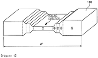
- FIG. 5 is a perspective view illustrating a material to be rolled which is rolled by a rolling roll according to an exemplary embodiment in the present disclosure
- FIGS. 6(a) to 6(e) are systematic views illustrating a stress state for each rolling position of FIG. 5 .
- the rolling roll (the first rolling roll) 132 used in the first rolling mill 130 in the present exemplary embodiment may have a structure having different diameters from a roll side portion along a barrel.
- the rolling roll 132 may be formed to generate a large amount of compressive stress in the rolling direction in the central portion in the width direction of the material during the rolling process to have an excellent surface deformation amount permeability into the central portion of the thickness of the material, and accordingly, to increase the surface deformation amount of the central portion, the diameter may be reduced toward both sides.
- the rolling roll 132 may include a portion having three steps with different diameters, and a gap between respective steps may be connected by two inclined curved surfaces which have a steep slope and are continuously connected to each other.
- the rolling roll 132 may include a first pressurization part 133 contacting a central portion of the material to be rolled 110 at a central portion of the barrel, a second pressurization part 135 forming the first inclined curved surface 134 on both sides of the first pressurization part 133, continuously decreasing in diameter to be smaller in diameter than the diameter of the first pressurization part 133 and forming a stepped portion, and a third pressurization part 137 forming the second inclined curved surface 136 on both sides of the second pressurization part 135, continuously decreasing in diameter to the edge of the barrel with a diameter smaller than the diameter of the second pressurization part 135 and forming a stepped portion.
- the first pressurization part 133 has a diameter R1 for providing a large amount of thickness deformation (reduction amount) in the thickness direction of the material in contact with the central portion in the width direction of the material to be rolled 110.
- the length extending in one direction based on the center of the barrel, in other words, the half length L1 of the first pressurization part 133 may be determined by the minimum width Wmin of the material to be rolled 110, which is a thick steel plate.
- the half length L1 of the first pressurization part 133 may be formed to be smaller than 0.2 times the minimum width Wmin of the material to be rolled 110, which is a thick steel plate (L1 ⁇ 0.2Wmin).
- the second pressurization part 135 may provide a smaller amount of thickness deformation (reduction amount) than that of the first pressurization part 133, and has a smaller diameter R2 than that of the first pressurization part 133 such that a compressive stress in the rolling direction of the material to be rolled 110 in contact with the first pressurization part 133 may be generated by limiting an elongation deformation in the length direction (rolling direction) of the material to be rolled 110 in contact with the first pressurization part 133.
- the third pressurization part 137 may give a smaller amount of thickness deformation (reduction amount) than the second pressurization part 135, and has a smaller diameter R3 than the second pressurization part 135 such that a compressive stress in the rolling direction of the material to be rolled 110 in contact with the second pressurization part 135 may be generated by limiting an elongation deformation in the length direction (rolling direction) of the material to be rolled 110 in contact with the second pressurization part 135.
- the length Ls1 of the first inclined curved surface 134 and the length Ls2 of the second inclined curved surface 136 may be formed to be smaller than 0.4 times the half length L1 of the first pressurization part 133 (Ls1 ⁇ 0.4L1, Ls2 ⁇ 0.4L1), respectively.
- the first inclined curved surface 134 and the second inclined curved surface 136 may be represented by an elliptic equation in which the diameter is rapidly reduced to restrain the width direction spreading of the material to be rolled 110 due to the differences in diameters of the respective pressurization parts 133, 135, and 137 by a large shear deformation.
- the first inclined curved surface 134 may be formed such that an end portion connected to the first pressurization part 133 and an end portion connected to the second pressurization part 135 are rounded. Further, the first inclined curved surface 134 may be connected such that a first curved surface in which one end is connected to the first pressurization part 133 and a second curved surface in which one end is connected to the other end of the first curved surface and the other end is connected to one end of the second pressurization part 135 have a quarter area of each elliptic curve.
- the first curved surface C1 and the second curved surface C2 may be determined by the following Equation 1.
- L1 is a half length of the first pressurization part 133
- Ls1 is a length of the first inclined curved surface 134
- Ls2 is a length of the second inclined curved surface 136
- R1 is a diameter of the first pressurization part 133
- a ds1 is a step between the first pressurization part 133 and the second pressurization part 135.
- the second inclined curved surface 136 may be formed such that an end portion connected to the second pressurization part 135 and an end portion connected to the third pressurization part 137 are rounded. Further, the second inclined curved surface 136 may be connected such that the third curved surface in which one end is connected to the second pressurization part 135 and the fourth curved surface in which one end is connected to the other end of the third curved surface and the other end is connected to one end of the third pressurization part 137 have a quarter area of each elliptic curve.
- the third curved surface C3 and the fourth curved surface C4 may be determined by the following Equation 2.
- L1 is a half length of the first pressurization part 133
- Ls1 is a length of the first inclined curved surface 134
- Ls2 is a length of the second inclined curved surface 136
- L2 is a length of the second pressurization part 135
- R2 is a diameter of the second pressurization part 135
- ds2 is a step between the second pressurization part 135 and the third pressurization part 137.
- the material to be rolled 110 in which an width edge portion thereof is rolled by a side rolling roll 142 (a second rolling roll) on both sides in the width direction in the second rolling mill 140 may be rolled to be supplied to the third rolling mill 150 and rolled by a double rolling roll 152 (a third rolling roll) and have a uniform thickness as a whole.
- the third rolling mill 150 provided for this purpose may include the double rolling roll 152 (the third rolling roll) for rolling portions outside of a central portion in the width direction of the material to be rolled 110.
- the double rolling roll 152 may be formed of a flat roll.
- the flat roll may be rolled by contacting from portions outside of the central portion of the width direction, not rolled by the rolling roll 132 when in contact with the material to be rolled 110.
- the double rolling roll 152 may be provided in a shaped roll in which a diameter decreases from the center of the barrel to both ends.
- the shaped roll may be less than 1mm in a diameter decreasing from the center of the barrel toward both ends.
- the central portion of the barrel is formed to have a larger diameter than both ends of the barrel, it may be continuously rolled while preventing a portion connected to the central portion, primarily rolled in the process of rolling the material to be rolled 110 from forming a step.
- FIGS. 7 (a) to 7 (c) are views illustrating an elongation amount in the length direction of the material rolled by the rolling system according to the related art and the present exemplary embodiment.
- FIGS. 7(a) to 7(c) illustrate that a material to be rolled 110 is rolled by the rolling system in the related art or the rolling system 100 of the present disclosure, under the condition that the material to be rolled 110 having a temperature of 1150°C has the thickness of 300mm, the width of 1500mm and the length of 1500mm, the rolling speed is 2.1m/sec, the reduction rate is 20%, and the maximum diameter of the work roll is 1200mm.
- FIG. 7(a) illustrates that it is rolled through the rolling system according to the related art, specifically, a general thin steel plate, a mid-thickness steel plate, and the like are rolled, and in detail, FIG. 7(a) illustrates an elongation amount by reducing a width of 40 mm by a vertical rolling mill which rolls in the width direction, and then reducing the thickness of 60 mm using a horizontal rolling mill.
- an elongation amount ( ⁇ C) of the central portion in the length direction is ⁇ 367.6mm
- an elongation amount ( ⁇ E) of the both end portions in the length direction is ⁇ 408mm
- a difference obtained by subtracting the elongation amount of the central portion from the elongation amount in the length direction is measured as 40.4 mm.
- FIG. 7(b) illustrates that a material is rolled through another rolling system sequentially passing through a rolling mill having a chamfered work roll of the related art and a rolling mill having a flat roll type work roll, as the present exemplary embodiment, which rolls the thick steel plate.
- the chamfered work roll used in B1 has a chamfer depth of 40mm, and a curvature of the round connected to the chamfer may be 200mm.
- an elongation amount of the central portion in the length direction ( ⁇ C) is ⁇ 360mm
- an elongation amount of both end portions in the length direction ( ⁇ E) is ⁇ 248.7mm in the material rolled by the rolling system in the related art.
- the difference obtained by subtracting the elongation amount of the central portion ( ⁇ C) in the length direction from the elongation amount in the length direction is measured as (-)111.3mm.
- FIG. 7(b) comparing FIG. 7(b) with FIG. 7(a) , it can be seen that there is no significant difference in the elongation amount in the central portion ( ⁇ C), but difference in the elongation amount of both end portions in the length direction( ⁇ E) is large, and it can be seen that it could not be sufficiently elongated at both end portions in the length direction as compared with the case of rolling a general steel plate.
- FIG. 7 (c) illustrates that a material is rolled by a rolling system of the present exemplary embodiment, it can be seen that an elongation amount of the central portion in the length direction ( ⁇ C) is ⁇ 362.3mm, an elongation amount of both end portions in the length direction ( ⁇ E) is ⁇ 411.9mm, in the material 110 rolled by the rolling system 100 according to the present exemplary embodiment , and the difference obtained by subtracting the elongation amount of the central portion from the elongation amount in the length direction is measured as 49.6mm.
- FIG. 7 (c) comparing FIG. 7 (c) with FIG. 7 (a) , it can be seen that it has almost no difference between the elongation amount of the central portion ( ⁇ C) and the elongation amount of both end portions in the length direction ( ⁇ E), and the same rolling characteristic may be obtained as in the case of rolling a thin steel plate, a middle-thick steel plate, and the like even when the thick steel plate is rolled in the present exemplary embodiment. Therefore, even when the ultra-thick steel plate is rolled by using the thick steel plate rolling mill with limited facility capacity, the surface deformation may be infiltrated to the central portion of the width direction and to the central portion of the thickness direction of the both end portions, thereby maintaining uniform overall quality.
- FIG. 8 is view illustrating a deformation rate in the thickness direction at the center position in the width direction of the material which is rolled by the rolling system according to the related art and the present exemplary embodiment.
- the material to be rolled 110 having a temperature of 1150°C has the thickness of 300mm, the width of 1500mm and the length of 1500mm, the rolling speed is 2.1m/sec, the reduction rate is 20%, and the maximum diameter of the work roll is 1200mm, the material is rolled by the rolling system of the related art and the rolling system 100 of the present disclosure.
- A1 is a line illustrating a deformation rate in the thickness direction at a center position in the width direction of the material which has passed through the general rolling mill of the related art.
- B1 is a line illustrating a deformation rate in the thickness direction at a center position in the width direction of the material which has passed through a rolling mill having a chamfered work roll of the related art
- B2 is a line illustrating a deformation rate in the thickness direction at a center position in the width direction of the material which has passed through the rolling mill having the chamfered work roll and the rolling mill having the flat type work roll in succession.
- the chamfered work roll used in B1 has a chamfer depth of 40mm. and the curvature of the round connected to the chamfer may be 200mm.
- C1 is a line illustrating the deformation rate in the thickness direction at a center position in the width direction of the material 110 which has passed through the rolling mill having the rolling roll 132 having a plurality of stepped portions in the present exemplary embodiment
- C2 is a line illustrating the deformation rate in the thickness direction at a center position in the width direction of the material 110 which has passed through the rolling mill having the rolling roll (the first rolling roll) 132 having a plurality of stepped portions in the present exemplary embodiment and the rolling mill having a double rolling roll (a third rolling roll)152 sequentially.
- a graph of FIG. 8 is measured assuming that a side rolling roll (a second rolling roll) 142 is not used considering the fact that the effect of the roll shape according to the use of the rolling mill having the rolling roll 132 in the width direction is changed.
- the deformation of the surface is easier to penetrate into the central portion as the deformation rate is higher under the same reduction amount (the same amount of decrease in thickness) condition.
- FIG. 9 is a view illustrating the torque ratio of the rolling system according to the related art and the present exemplary embodiment.
- FIG. 9 it is a graph illustrating torque ratios of the rolling system according to the related art and the present exemplary embodiment. It could be confirmed that the torque imbalance occurring during the primary rolling in the thickness direction of the material to be rolled 110 and the secondary rolling after the primary rolling is reduced in the rolling system 100 of the present exemplary embodiment. As such, it could be confirmed that the rolling system 100 of the present exemplary embodiment may improve the torque imbalance which occurs between the rolling mills of the prior art.
- FIG. 10 is a view illustrating a grain size in the thickness direction at the center position in the width direction of the material which is rolled by the rolling system according to the related art and the present exemplary embodiment.
- a grain size in the thickness direction at the center position of the material which is rolled by a general rolling mill in the related art, a rolling mill having a chamfered rolling roll 132 in other related art, or a rolling mill having a rolling roll 132 (a first rolling roll and a third rolling roll) in the present exemplary embodiment, may be found.
- an average grain size after rolling to the conventional general rolling system disclosed in the X1 line is 148mm
- an average grain size after rolling to the rolling system including a rolling mill having a conventional chamfered work roll disclosed in the Y1 line is 85.3mm
- an average grain size after rolling to the rolling system 100 including a rolling mill having the multi-stepped portions of the present exemplary embodiment disclosed in the Z1 line is greatly reduced to 67.5mm.
- a range of the grain size in the thickness direction which has a major influence on the increase of the mechanical properties of the material to be rolled 110 is 83 to 228mm in the case of the general rolling system of the related art, is 61 to 129mm in the case of the rolling system including a rolling mill having a chamfered work roll of the related art, however, is 56 to 73mm, in the case of the rolling system 100 including the rolling roll (first rolling roll) 132 having the multi-stepped portions of the present exemplary embodiment.
- the difference in mechanical properties in the thickness direction of the material to be rolled 110 is small as the difference in the grain size is smaller in the thickness direction of the material to be rolled, and it can be seen that uniformity is greatly improved, in the case of the rolling system 100 including a rolling roll (a first rolling roll) 132 having multi-stepped portions of the present exemplary embodiment, in consideration thereof.
- FIG. 11 is a view illustrating a deformation rate in the thickness direction at the central position in the width direction of the material which is rolled by the rolling system according to the related art and the present exemplary embodiment.
- the material to be rolled 110 having a temperature of 1150°C has the thickness of 300mm, the width of 1500mm and the length of 1500mm, the rolling speed is 2.1m/sec, and the maximum diameter of the work roll is 1200mm
- the reduction rate is 13% in the case of the rolling system of the related art disclosed in a X2 line
- the average deformation rate in the thickness direction is 0.18.
- the reduction rate is 20% in the case of the rolling system including the rolling mill having the chamfered work roll of the related art disclosed in a Y2 line
- the average deformation rate in the thickness direction is 0.28.
- the average deformation rate is 0.45 despite the fact that the reduction rate is 13% in the case of the rolling system 100 including the rolling roll (the first rolling roll) 132 having the multi-stepped portions of the present exemplary embodiment disclosed in the Z2 line.
- the value of the average deformation rate of 0.45 is a value which may not be achieved in a conventional rolling mill due to constraints of the facility load and the facility torque of the rolling mill.
- the torque ratios of the continuous system of the present exemplary embodiment are 0.98 (the first rolling mill 130) and 1.0 (the second rolling mill 140), which do not deviate from the specifications of conventional rolling motors.
- the present disclosure is useful in the thick steel plate rolling process.
Landscapes
- Engineering & Computer Science (AREA)
- Mechanical Engineering (AREA)
- Physics & Mathematics (AREA)
- Geometry (AREA)
- Metal Rolling (AREA)
- Reduction Rolling/Reduction Stand/Operation Of Reduction Machine (AREA)
Applications Claiming Priority (2)
| Application Number | Priority Date | Filing Date | Title |
|---|---|---|---|
| KR1020160044308A KR101767825B1 (ko) | 2016-04-11 | 2016-04-11 | 압연롤 및 이를 포함하는 압연 시스템 |
| PCT/KR2016/014241 WO2017179791A1 (ko) | 2016-04-11 | 2016-12-06 | 압연롤 및 이를 포함하는 압연 시스템 |
Publications (2)
| Publication Number | Publication Date |
|---|---|
| EP3444043A1 true EP3444043A1 (de) | 2019-02-20 |
| EP3444043A4 EP3444043A4 (de) | 2019-05-08 |
Family
ID=60042125
Family Applications (1)
| Application Number | Title | Priority Date | Filing Date |
|---|---|---|---|
| EP16898753.5A Withdrawn EP3444043A4 (de) | 2016-04-11 | 2016-12-06 | Walze und walzsystem damit |
Country Status (5)
| Country | Link |
|---|---|
| EP (1) | EP3444043A4 (de) |
| JP (1) | JP2019510638A (de) |
| KR (1) | KR101767825B1 (de) |
| CN (1) | CN108883449A (de) |
| WO (1) | WO2017179791A1 (de) |
Families Citing this family (3)
| Publication number | Priority date | Publication date | Assignee | Title |
|---|---|---|---|---|
| CN110280593B (zh) * | 2019-06-26 | 2024-08-13 | 南京钢铁股份有限公司 | 不产生台阶的窄带钢用三辊型粗轧机及其孔型确定方法 |
| EP4031509A4 (de) | 2019-09-18 | 2024-01-10 | Massachusetts Institute of Technology | Systeme, zusammensetzungen und verfahren zur herstellung von scharfen kanten |
| CN112222186A (zh) * | 2020-09-18 | 2021-01-15 | 太原理工大学 | 一种高精度生产变厚板的装置及方法 |
Family Cites Families (12)
| Publication number | Priority date | Publication date | Assignee | Title |
|---|---|---|---|---|
| JPS534177Y2 (de) * | 1972-11-16 | 1978-02-02 | ||
| JPS619109U (ja) * | 1984-06-22 | 1986-01-20 | 川崎製鉄株式会社 | 多段圧延装置 |
| JPS6146306A (ja) * | 1984-08-09 | 1986-03-06 | Sumitomo Metal Ind Ltd | 圧延ロ−ル |
| JPH02175001A (ja) * | 1988-12-27 | 1990-07-06 | Kawasaki Steel Corp | 粗形鋼片の圧延方法 |
| JP2004050221A (ja) * | 2002-07-18 | 2004-02-19 | Ishikawajima Harima Heavy Ind Co Ltd | 帯板製造設備及び帯板製造方法 |
| JP2010082659A (ja) * | 2008-09-30 | 2010-04-15 | Panasonic Corp | 金属シート成形用ロールおよび金属シートの成形方法 |
| JP5494058B2 (ja) * | 2010-03-16 | 2014-05-14 | 新日鐵住金株式会社 | 圧延機 |
| DE102010029598A1 (de) * | 2010-06-01 | 2011-12-01 | ACHENBACH BUSCHHüTTEN GMBH | Stützwalze und damit ausgerüstetes Walzgerüst |
| KR101433432B1 (ko) * | 2011-12-27 | 2014-08-26 | 주식회사 포스코 | 챔퍼를 형성시키는 단차롤의 설계 방법과, 이를 이용한 후강판 제조장치 및 제조방법 |
| KR101480487B1 (ko) * | 2012-12-27 | 2015-01-09 | 주식회사 포스코 | 극후강판 제조를 위한 압연기 작업롤과 압연기 및 이를 이용한 압연 방법 |
| KR101438774B1 (ko) * | 2012-12-27 | 2014-09-05 | 주식회사 포스코 | 극후강판 압연 설비와 압연 방법 |
| DE102014005085A1 (de) | 2014-04-08 | 2015-10-08 | Sms Meer Gmbh | Mehrwalzentischringwalzwerk sowie Verfahren zum Walzen von Ringen in einem Mehrwalzentischringwalzwerk |
-
2016
- 2016-04-11 KR KR1020160044308A patent/KR101767825B1/ko active Active
- 2016-12-06 WO PCT/KR2016/014241 patent/WO2017179791A1/ko not_active Ceased
- 2016-12-06 JP JP2018550379A patent/JP2019510638A/ja active Pending
- 2016-12-06 CN CN201680084518.5A patent/CN108883449A/zh active Pending
- 2016-12-06 EP EP16898753.5A patent/EP3444043A4/de not_active Withdrawn
Also Published As
| Publication number | Publication date |
|---|---|
| KR101767825B1 (ko) | 2017-08-14 |
| WO2017179791A1 (ko) | 2017-10-19 |
| JP2019510638A (ja) | 2019-04-18 |
| CN108883449A (zh) | 2018-11-23 |
| EP3444043A4 (de) | 2019-05-08 |
Similar Documents
| Publication | Publication Date | Title |
|---|---|---|
| EP3205415B1 (de) | Verfahren zur herstellung einer metallplatte mit vorstehendem wulst | |
| US11638941B2 (en) | Systems and methods for controlling flatness of a metal substrate with low pressure rolling | |
| EP3444043A1 (de) | Walze und walzsystem damit | |
| EP3473346B1 (de) | Verfahren zum kaltwalzen eines stahlblechs und verfahren zur herstellung eines stahlblechs | |
| JP5131929B2 (ja) | 連続圧延機を用いた分塊圧延方法 | |
| EP2156908B1 (de) | Verfahren zur herstellung eines nahtlosen rohrs | |
| JP2009208082A (ja) | 平面性が優れたアルミニウム条材の製造方法 | |
| CN101765466B (zh) | 板轧制的轧制道次规程的设定方法 | |
| EP2796216B1 (de) | Bandförmiges blech | |
| JP5928221B2 (ja) | 冷延鋼板の調質圧延方法 | |
| KR101433432B1 (ko) | 챔퍼를 형성시키는 단차롤의 설계 방법과, 이를 이용한 후강판 제조장치 및 제조방법 | |
| KR101485629B1 (ko) | 챔퍼 슬래브의 압하량 설정 방법 및 이를 이용한 후강판 제조방법 | |
| KR102393094B1 (ko) | 3롤 압연 시스템 | |
| EP3257597B1 (de) | Verfahren zur herstellung von h-förmigem stahl | |
| KR101480487B1 (ko) | 극후강판 제조를 위한 압연기 작업롤과 압연기 및 이를 이용한 압연 방법 | |
| JP6427738B2 (ja) | 冷間圧延方法 | |
| JP4568164B2 (ja) | 差厚鋼板の圧延矯正方法 | |
| KR101438774B1 (ko) | 극후강판 압연 설비와 압연 방법 | |
| KR101537387B1 (ko) | 극후강판 제조를 위한 압연기 백업롤과 이를 이용한 압연기 | |
| JP6572501B2 (ja) | 冷間圧延用ワークロール | |
| JP2013111637A (ja) | 冷延鋼板の圧延方法および極薄鋼板の製造方法 | |
| JP2007118024A (ja) | ローラーレベラーによる金属板の矯正方法。 | |
| RU2360977C2 (ru) | Холоднокатаная полоса из малоуглеродистой стали 08ю для холодной штамповки | |
| JP6733396B2 (ja) | 圧延機 | |
| JP2008238173A (ja) | 板圧延のパススケジュールの設定方法 |
Legal Events
| Date | Code | Title | Description |
|---|---|---|---|
| STAA | Information on the status of an ep patent application or granted ep patent |
Free format text: STATUS: THE INTERNATIONAL PUBLICATION HAS BEEN MADE |
|
| PUAI | Public reference made under article 153(3) epc to a published international application that has entered the european phase |
Free format text: ORIGINAL CODE: 0009012 |
|
| STAA | Information on the status of an ep patent application or granted ep patent |
Free format text: STATUS: REQUEST FOR EXAMINATION WAS MADE |
|
| 17P | Request for examination filed |
Effective date: 20181108 |
|
| AK | Designated contracting states |
Kind code of ref document: A1 Designated state(s): AL AT BE BG CH CY CZ DE DK EE ES FI FR GB GR HR HU IE IS IT LI LT LU LV MC MK MT NL NO PL PT RO RS SE SI SK SM TR |
|
| AX | Request for extension of the european patent |
Extension state: BA ME |
|
| A4 | Supplementary search report drawn up and despatched |
Effective date: 20190405 |
|
| RIC1 | Information provided on ipc code assigned before grant |
Ipc: B21B 27/02 20060101AFI20190401BHEP Ipc: B21B 1/24 20060101ALI20190401BHEP |
|
| DAV | Request for validation of the european patent (deleted) | ||
| DAX | Request for extension of the european patent (deleted) | ||
| STAA | Information on the status of an ep patent application or granted ep patent |
Free format text: STATUS: EXAMINATION IS IN PROGRESS |
|
| 17Q | First examination report despatched |
Effective date: 20210202 |
|
| STAA | Information on the status of an ep patent application or granted ep patent |
Free format text: STATUS: THE APPLICATION IS DEEMED TO BE WITHDRAWN |
|
| 18D | Application deemed to be withdrawn |
Effective date: 20210615 |