EP3444133A2 - Stratégie de conception d'admission d'air hvac à deux portes pour système de climatisation de véhicule - Google Patents
Stratégie de conception d'admission d'air hvac à deux portes pour système de climatisation de véhicule Download PDFInfo
- Publication number
- EP3444133A2 EP3444133A2 EP18184509.0A EP18184509A EP3444133A2 EP 3444133 A2 EP3444133 A2 EP 3444133A2 EP 18184509 A EP18184509 A EP 18184509A EP 3444133 A2 EP3444133 A2 EP 3444133A2
- Authority
- EP
- European Patent Office
- Prior art keywords
- opening
- door
- recirculation
- air
- intake
- Prior art date
- Legal status (The legal status is an assumption and is not a legal conclusion. Google has not performed a legal analysis and makes no representation as to the accuracy of the status listed.)
- Withdrawn
Links
Images




Classifications
-
- B—PERFORMING OPERATIONS; TRANSPORTING
- B60—VEHICLES IN GENERAL
- B60H—ARRANGEMENTS OF HEATING, COOLING, VENTILATING OR OTHER AIR-TREATING DEVICES SPECIALLY ADAPTED FOR PASSENGER OR GOODS SPACES OF VEHICLES
- B60H1/00—Heating, cooling or ventilating devices
- B60H1/00642—Control systems or circuits; Control members or indication devices for heating, cooling or ventilating devices
- B60H1/00664—Construction or arrangement of damper doors
-
- B—PERFORMING OPERATIONS; TRANSPORTING
- B60—VEHICLES IN GENERAL
- B60H—ARRANGEMENTS OF HEATING, COOLING, VENTILATING OR OTHER AIR-TREATING DEVICES SPECIALLY ADAPTED FOR PASSENGER OR GOODS SPACES OF VEHICLES
- B60H1/00—Heating, cooling or ventilating devices
- B60H1/00642—Control systems or circuits; Control members or indication devices for heating, cooling or ventilating devices
- B60H1/00814—Control systems or circuits characterised by their output, for controlling particular components of the heating, cooling or ventilating installation
- B60H1/00821—Control systems or circuits characterised by their output, for controlling particular components of the heating, cooling or ventilating installation the components being ventilating, air admitting or air distributing devices
- B60H1/00835—Damper doors, e.g. position control
- B60H1/00849—Damper doors, e.g. position control for selectively commanding the induction of outside or inside air
-
- B—PERFORMING OPERATIONS; TRANSPORTING
- B60—VEHICLES IN GENERAL
- B60H—ARRANGEMENTS OF HEATING, COOLING, VENTILATING OR OTHER AIR-TREATING DEVICES SPECIALLY ADAPTED FOR PASSENGER OR GOODS SPACES OF VEHICLES
- B60H1/00—Heating, cooling or ventilating devices
- B60H1/00007—Combined heating, ventilating, or cooling devices
- B60H1/00021—Air flow details of HVAC devices
-
- B—PERFORMING OPERATIONS; TRANSPORTING
- B60—VEHICLES IN GENERAL
- B60H—ARRANGEMENTS OF HEATING, COOLING, VENTILATING OR OTHER AIR-TREATING DEVICES SPECIALLY ADAPTED FOR PASSENGER OR GOODS SPACES OF VEHICLES
- B60H1/00—Heating, cooling or ventilating devices
- B60H1/00007—Combined heating, ventilating, or cooling devices
- B60H1/00021—Air flow details of HVAC devices
- B60H1/00028—Constructional lay-out of the devices in the vehicle
-
- B—PERFORMING OPERATIONS; TRANSPORTING
- B60—VEHICLES IN GENERAL
- B60H—ARRANGEMENTS OF HEATING, COOLING, VENTILATING OR OTHER AIR-TREATING DEVICES SPECIALLY ADAPTED FOR PASSENGER OR GOODS SPACES OF VEHICLES
- B60H1/00—Heating, cooling or ventilating devices
- B60H1/00642—Control systems or circuits; Control members or indication devices for heating, cooling or ventilating devices
- B60H1/00664—Construction or arrangement of damper doors
- B60H1/00671—Damper doors moved by rotation; Grilles
-
- B—PERFORMING OPERATIONS; TRANSPORTING
- B60—VEHICLES IN GENERAL
- B60H—ARRANGEMENTS OF HEATING, COOLING, VENTILATING OR OTHER AIR-TREATING DEVICES SPECIALLY ADAPTED FOR PASSENGER OR GOODS SPACES OF VEHICLES
- B60H1/00—Heating, cooling or ventilating devices
- B60H1/00642—Control systems or circuits; Control members or indication devices for heating, cooling or ventilating devices
- B60H1/00664—Construction or arrangement of damper doors
- B60H1/00671—Damper doors moved by rotation; Grilles
- B60H1/00685—Damper doors moved by rotation; Grilles the door being a rotating disc or cylinder or part thereof
-
- B—PERFORMING OPERATIONS; TRANSPORTING
- B60—VEHICLES IN GENERAL
- B60H—ARRANGEMENTS OF HEATING, COOLING, VENTILATING OR OTHER AIR-TREATING DEVICES SPECIALLY ADAPTED FOR PASSENGER OR GOODS SPACES OF VEHICLES
- B60H1/00—Heating, cooling or ventilating devices
- B60H1/00642—Control systems or circuits; Control members or indication devices for heating, cooling or ventilating devices
- B60H1/00814—Control systems or circuits characterised by their output, for controlling particular components of the heating, cooling or ventilating installation
- B60H1/00821—Control systems or circuits characterised by their output, for controlling particular components of the heating, cooling or ventilating installation the components being ventilating, air admitting or air distributing devices
- B60H1/00835—Damper doors, e.g. position control
- B60H1/00842—Damper doors, e.g. position control the system comprising a plurality of damper doors; Air distribution between several outlets
-
- B—PERFORMING OPERATIONS; TRANSPORTING
- B60—VEHICLES IN GENERAL
- B60H—ARRANGEMENTS OF HEATING, COOLING, VENTILATING OR OTHER AIR-TREATING DEVICES SPECIALLY ADAPTED FOR PASSENGER OR GOODS SPACES OF VEHICLES
- B60H1/00—Heating, cooling or ventilating devices
- B60H1/00007—Combined heating, ventilating, or cooling devices
- B60H1/00021—Air flow details of HVAC devices
- B60H2001/00078—Assembling, manufacturing or layout details
- B60H2001/00085—Assembling, manufacturing or layout details of air intake
-
- B—PERFORMING OPERATIONS; TRANSPORTING
- B60—VEHICLES IN GENERAL
- B60H—ARRANGEMENTS OF HEATING, COOLING, VENTILATING OR OTHER AIR-TREATING DEVICES SPECIALLY ADAPTED FOR PASSENGER OR GOODS SPACES OF VEHICLES
- B60H1/00—Heating, cooling or ventilating devices
- B60H1/00007—Combined heating, ventilating, or cooling devices
- B60H1/00021—Air flow details of HVAC devices
- B60H2001/00185—Distribution of conditionned air
-
- B—PERFORMING OPERATIONS; TRANSPORTING
- B60—VEHICLES IN GENERAL
- B60H—ARRANGEMENTS OF HEATING, COOLING, VENTILATING OR OTHER AIR-TREATING DEVICES SPECIALLY ADAPTED FOR PASSENGER OR GOODS SPACES OF VEHICLES
- B60H1/00—Heating, cooling or ventilating devices
- B60H1/00642—Control systems or circuits; Control members or indication devices for heating, cooling or ventilating devices
- B60H1/00664—Construction or arrangement of damper doors
- B60H2001/00721—Air deflecting or air directing means
Definitions
- the disclosed inventive concept relates generally to heating, ventilating and air conditioning (HVAC) systems for vehicles. More particularly, the disclosed inventive concept relates to a two-door HVAC air intake design strategy for an automotive vehicle that optimizes power consumption while providing for a desirable level of recirculated air.
- the passage of air is regulated by a pair of rotary doors.
- One of the rotary doors alternatively regulates the passage of fresh air and recirculated air.
- the other rotary door regulates only the passage of recirculated air.
- the two-door HVAC air design provides for three settings including a fresh air setting in which both doors are closed, a partial recirculated air setting in which one of the doors is closed and one of the door is open, and a full recirculation setting in which both doors are open.
- the rotary doors may be shell doors or flap doors.
- the amount of outside air brought into the cabin must be minimized and the amount of cabin air being recirculated must be maximized.
- the power consumption will be minimized when 100% cabin air recirculation is used.
- 100% cabin air recirculation may cause the fogging of the inner surfaces of the vehicle's windows (including the windshield) results. Consequently, an amount of outside air is needed to be brought into the vehicle to prevent cabin interior fogging.
- a full fresh air mode in cold weather results in a reduction of heater/defroster performance. If a full fresh air mode is selected in hot weather, an increased cooling load will be imposed on the air conditioning compressor.
- HVAC heating, ventilation and air conditioning
- the disclosed invention provides a two-door HVAC air intake system and method of efficiently selecting air intake between a full fresh air mode, a partial recirculated air mode and full recirculated air mode.
- the disclosed invention provides optimum heating/cooling performance, fuel economy and/or high voltage (HV) battery power consumption.
- the HVAC air intake design incorporates two rotary doors that, working in combination with a fresh air opening and two recirculated air openings, allow for the selection between the full fresh air mode, the partial recirculated air mode, and the full recirculated air mode.
- One of the two doors provides for selection between recirculation and fresh air.
- the other of the two doors selects for recirculation.
- the rotary doors may be shell doors or flap doors.
- the intake system manages the doors to move progressively to any position based on exterior and interior air conditions as well as cooling and heating loads as well as cabin fogging probability. With the increase of cooling and heating loads, the system is moved toward full the recirculation mode. Conversely, with the increase of surface fogging, the system is moved toward the full fresh air mode.
- the disclosed two-door HVAC air intake design provides an air intake design including an air intake body having a fresh air opening, a first recirculated air opening, and a second recirculated air opening.
- a first rotary door and a second rotary door are pivotably disposed in the body.
- the first rotary door is reversibly movable from a first recirculation opening-unblocking/fresh air opening-blocking position to a first recirculation opening-blocking/fresh air opening-unblocking position.
- the second rotary door is reversibly movable from a second recirculation opening-unblocking position to a second recirculation opening-blocking position.
- the first recirculated air opening and said second recirculated air opening may be situated side-by-side and the fresh air opening is situated adjacent the first recirculated air opening.
- the fresh air opening may be situated between the first recirculated air opening and the second recirculated air opening.
- the first and second rotary doors are moved to their recirculation opening-blocking positions.
- the first rotary door is moved to its first recirculation opening-blocking position and the second rotary door is moved to its second recirculation opening-unblocking position.
- the first rotary door is moved to its first recirculation opening-unblocking/fresh air opening-blocking position and the second rotary door is moved to its second recirculation opening-unblocking position.
- the disclosed inventive concept By selectively choosing a position between the full recirculation mode and the full fresh air mode, a low air side pressure drop is achieved, thereby improving system efficiency.
- the system of the disclosed inventive concept minimizes the rush of air and thus improves vehicle noise, vibration and harshness (NVH).
- the disclosed inventive design concept prevents the bypass of fresh air from outside of the vehicle directly into the vehicle's cabin.
- FIGS. 1 through 8 and 10 illustrate the two-door HVAC air intake system according to one embodiment of the disclosed inventive concept.
- FIG. 11 Another embodiment of the disclosed inventive concept is illustrated in FIG. 11 .
- the two rotary shell doors of the first embodiment of the disclosed inventive concept are shown in isolation in FIG. 9 . These shell doors may be usable in any embodiment of the disclosed inventive concept.
- flap doors may alternatively be used as one or both of the rotary doors.
- FIGS. 12 and 13 illustrate the various figures illustrated the two-door HVAC air intake system in its various modes of operation.
- FIGS. 1 through 10 an embodiment of the two-door HVAC air intake is illustrated.
- the air intake is illustrated in perspective views from a first angle in FIGS. 1 and 2 wherein the whole intake is illustrated in FIG. 1 and the upper portion of the intake is illustrated in FIG. 2 .
- a two-door HVAC air intake is generally illustrated as 10.
- the two-door HVAC air intake 10 includes an upper gate portion 12 and a lower blower portion 14, the latter being shown only in FIG. 1 .
- the two-door HVAC air intake 10 further includes a conduit connector 16 for electrical connection to the vehicle's power system (not shown).
- An interchangeable filter element 18 is provided between the upper gate portion 12 and the lower blower portion 14.
- a first recirculation opening 20 is formed in the upper gate portion 12.
- a first shell (rotary) door 21 is pivotably provided adjacent the first recirculation opening 20.
- a second recirculation opening 22 is formed in the upper gate portion 12.
- a second shell (rotary) door 23 is pivotably provided adjacent the second recirculation opening 22.
- At least one door controller 24 is provided to selectively pivotably move the first shell door 21 and the second shell door 23.
- the door controller 24 may be any one of several actuators (including, for example and without limitation, electric motors and vacuum controllers).
- the door controller 24 is an electric servo motor provided whereby the positions of the first shell door 21 and the second shell door 23 are continuously variable.
- FIG. 3 illustrates a perspective view of the upper gate portion 12 from the side opposite that of FIG. 2 .
- a fresh air opening 26 is illustrated.
- the shape and position of the fresh air opening 26 may be varied from that illustrated.
- the first shell door 21 is attached to the upper gate portion 12 by opposed pivot points of which one, a pivot point 28 is illustrated.
- the second shell door 23 is also attached to the upper gate portion 12 by opposed pivot points of which one, a pivot point 30 is illustrated.
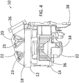
- FIGS. 4 through 6 Side views of the two-door HVAC air intake 10 are illustrated in FIGS. 4 through 6 which the various modes of the disclosed inventive concept are shown. Particularly, and referring to FIG. 4 , the two-door HVAC air intake 10 is in its fresh air mode. This mode is achieved by, first, rotation of the first shell door 21 to a position in which the first recirculation opening 20 is blocked and the fresh air opening 26 is unblocked and, second, rotation of the second shell door 23 to a position in which the second recirculation opening 22 is blocked, the first and second actions preferably being simultaneous.
- the two-door HVAC air intake 10 is in its partial recirculation mode. This mode is achieved by, first, rotation of the first shell door 21 to a position in which the first recirculation opening 20 is blocked and the fresh air opening 26 is unblocked and, second, rotation of the second shell door 23 to a position in which the second recirculation opening 22 is unblocked, the first and second actions preferably being simultaneous.
- the two-door HVAC air intake 10 is in its full recirculation mode. This mode is achieved by, first, rotation of the first shell door 21 to a position in which the first recirculation opening 20 is unblocked and the fresh air opening 26 is blocked and, second, rotation of the second shell door 23 to a position in which the second recirculation opening 22 is unblocked, the first and second actions preferably being simultaneous.
- the positions of the first shell door 21 and the second shell door 23 relative to the fresh air mode, the partial recirculation mode and the recirculation mode are generally set forth in the following table: Shell (rotary) door position Fresh Air Partial Recirculation Recirculation First Shell Door 21 Moved to block off first recirculation opening (fresh air opening unblocked) Moved to block off first recirculation opening (fresh air opening unblocked) Moved to block off fresh air opening (first recirculation opening unblocked) Second Shell Door 23 Moved to block off second recirculation opening Moved to unblock second recirculation opening Moved to unblock second recirculation opening
- first shell door 21 and the second shell door 23 may be such that the doors 21 and 23 may be positioned anywhere between their fully closed and fully opened positions.
- the system therefore provides virtually infinite tunability as needed for maximum cabin comfort and minimum energy consumption.
- FIGS. 4 through 6 also illustrate a blower assembly 32 being part of the lower blower portion 24.
- the blower assembly 32 includes variable speed blower motor 34 and a blower wheel 36 attached thereto.
- the two-door HVAC air intake 10 is attached to a body structure (not shown) by one or more support brackets 38 which is illustrated as being suggestive and not limiting.
- the upper gate portion 12 includes an arrangement of internal seals to minimize air blow-by and the related reduction of efficiency and the requirement of increased energy consumption, specifically preventing the bypass of outside air into the cabin.
- an air seal arrangement 40 is illustrated against which the a portion of the second shell door 23 rests when moved from the fresh mode in which the second shell door 23 blocks the second recirculation opening 22 as illustrated in FIG. 7 to the partial recirculation mode in which the second shell door 23 is moved to a position in which the second recirculation opening 22 is unblocked (as illustrated in FIGS. 8 and 10 ).
- the first shell door 21 and the second shell door 23 are illustrated in isolation in FIG. 9 . It is to be understood that the specific shapes and structures of the doors 21 and 23 as illustrated are suggestive and are not intended as being limiting.
- the shell door 21 includes a door wall 42 supported by a door frame 44.
- a door seal 46 is formed on the outer side of the door frame 44.
- the shell door 23 includes a door wall 48 supported by a door frame 50.
- a door seal 52 is formed on the outer side of the door frame 50. The door seals 46 and 52 provide an airtight seal within the upper gate portion 12 between the shell doors 21 and 23 and the inner surfaces of the upper gate portion 12.
- sealing arrangements for the shell door 21 and the shell door 23 are illustrated. Particularly, a door seal 53 is provided for sealing the door 21 when rotated to its fresh air passing position while a door seal 54 is provided for sealing the door 23 when rotated to its recirculated air passing position.
- FIGS. 1 through 8 and 10 The embodiment of the two-door HVAC air intake illustrated in FIGS. 1 through 8 and 10 as shown and as discussed above is one suggested embodiment in which the first recirculated air opening 20 and the second recirculated air opening 22 are situated side-by-side and the fresh air opening 26 is situated adjacent the first recirculated air opening 20.
- FIG. 11 One such alternative embodiment is illustrated in FIG. 11 .
- an upper gate portion 60 is illustrated in sectional view.
- the upper gate portion 60 includes a filter element 62.
- a first recirculation opening 64 is provided having a first shell (rotary) door 66.
- the first shell door 66 is made pivotable with respect to the gate portion 60 by a first shell pivot 68.
- a second recirculation opening 70 is provided having a second shell (rotary) door 72.
- the second shell door 72 is made pivotable with respect to the gate portion 60 by a second shell pivot 74.
- a fresh air opening 76 is positioned between the first recirculation opening 64 and the second recirculation opening 70.
- the position of the first shell door 66 is shown blocking the first recirculation opening 64 while the position of the second shell door 72 is shown a position in which the second recirculation opening 70 is open, thereby representing the partial recirculation mode.
- the incoming fresh air (“F.A.”) passes into the fresh air opening 76 and the incoming recirculated air (“R.A.”) passes into the second recirculation opening 70 and through the filter element 62 of the upper gate portion 60 and into the vehicle's cabin (not illustrated).
- a sealing arrangement is provided in the upper gate portion 60 to maintain a tight seal of the shell doors.
- a lower air seal 78 and an upper air seal 80 are provided to minimize the risk of air bypassing the second shell door 72 when moved to its position in which the second recirculation opening 70 is unblocked.
- a lower seal 82 and an upper seal 84 are provided to minimize the risk of air bypassing the first shell door 66 when moved to its position in which the first recirculation door opening 64 is blocked.
- FIGS. 1 through 11 The embodiments of the two-door HVAC air intake illustrated in FIGS. 1 through 11 as shown and as discussed above are suggested embodiments in which a rotary shell door is utilized.
- a flap door may be utilized. This arrangement is illustrated in FIGS. 12 and 13 .
- an upper gate portion 90 is illustrated in sectional view.
- the upper gate portion 90 includes a filter element 92.
- a first recirculation opening 94 is provided having a flap door 96.
- the flap door 96 is made pivotable with respect to the upper gate portion 90 by a flap pivot 98.
- a second recirculation opening 100 is provided having a rotary shell door 102.
- the rotary shell door 102 is made pivotable with respect to the upper gate portion 90 by a rotary shell door pivot 104.
- a fresh air opening 106 is positioned adjacent the first recirculation opening 94 although the fresh air opening 106 could also be positioned between the first recirculation opening 94 and the second recirculation opening 100.
- the position of the flap door 96 can be either a flap fresh air blocking position ("F.A.B.”, shown in broken lines) or a flap recirculated air blocking position ("R.A.B.”, also shown in broken lines).
- a sealing arrangement is provided in the upper gate portion 90 to maintain a tight seal of the doors.
- a lower air seal 107 is provided to minimize the risk of air bypassing the flap door 96 when moved to its fresh air blocking position (as illustrated).
- An upper air seal 108 is provided to minimize the risk of air bypassing the flap door 96 when moved to its recirculated air blocking position.
- a seal 109 is provided to minimize the risk of air bypassing the rotary shell door 102 when moved to its closed position as illustrated in FIG. 12 .
- FIG. 12 illustrates a flap door positioned to select between passage of fresh air and recirculated air through the first recirculation opening
- flap door may also be used to regulate passage of recirculated air through the second recirculation opening as illustrated in FIG. 13 .
- flap doors may be used to regulate the passage of recirculated air through both the first and second recirculation openings.
- an upper gate portion 110 is illustrated in sectional view.
- the upper gate portion 110 includes a filter element 112.
- a first recirculation opening 114 is provided having a rotary shell door 116.
- the rotary shell door 116 is made pivotable with respect to the upper gate portion 110 by a flap pivot 118.
- a second recirculation opening 120 is provided having a flap door 122.
- the flap door 122 is made pivotable with respect to the upper gate portion 110 by a rotary shell door pivot 124.
- a fresh air opening 126 is positioned between the first recirculation opening 114 and the second recirculation opening 120.
- the fresh air opening 126 could be positioned adjacent the first recirculation opening 114.
- the position of the flap door 122 can be either a recirculated air blocking position ("R.A.B.”, shown in broken lines) or a flap recirculated air passing position ("R.A.P.”, also shown in broken lines).
- a sealing arrangement is provided in the upper gate portion 110 to maintain a tight seal of the doors. Particularly, and as illustrated in FIG. 13 , a lower air seal 128 and an upper air seal 130 are provided to minimize the risk of air bypassing the rotary shell door 116 when moved to its position in which the first recirculation opening 114 is blocked as illustarted.
- the specific movement of the first door relative to the first recirculation opening and the fresh air opening and the specific movement of the second door relative to the second recirculation opening are controlled by vehicle components that regulate blower speed, temperature in the cabin, the direction of air flow and the ratio of fresh air to recirculated air.
- vehicle components that regulate blower speed, temperature in the cabin, the direction of air flow and the ratio of fresh air to recirculated air.
- sensors not shown.
- An electronic controller and associated operating software generate signals to control the door actuators according to the conditions as indicated by the sensors.
- the disclosed inventive concept provides for economic operation of the vehicle's HVAC system whereby fuel economy and/or high voltage (HV) batter power consumption is minimized while providing optimum heating and cooling performance to thereby provide a comfortable in-cabin experience for vehicle passengers.
- HV high voltage
- the disclosed inventive concept achieves the noted advantages without adding weight, cost, or complexity to the HVAC system of the vehicle.
- the disclosed inventive concept may be used with any type of vehicle.
Landscapes
- Physics & Mathematics (AREA)
- Thermal Sciences (AREA)
- Engineering & Computer Science (AREA)
- Mechanical Engineering (AREA)
- Air-Conditioning For Vehicles (AREA)
Applications Claiming Priority (1)
| Application Number | Priority Date | Filing Date | Title |
|---|---|---|---|
| US15/680,964 US20190054799A1 (en) | 2017-08-18 | 2017-08-18 | Two-Door HVAC Air Intake Design Strategy For Vehicle Air Conditioning System |
Publications (2)
| Publication Number | Publication Date |
|---|---|
| EP3444133A2 true EP3444133A2 (fr) | 2019-02-20 |
| EP3444133A3 EP3444133A3 (fr) | 2019-07-17 |
Family
ID=63012921
Family Applications (1)
| Application Number | Title | Priority Date | Filing Date |
|---|---|---|---|
| EP18184509.0A Withdrawn EP3444133A3 (fr) | 2017-08-18 | 2018-07-19 | Stratégie de conception d'admission d'air hvac à deux portes pour système de climatisation de véhicule |
Country Status (3)
| Country | Link |
|---|---|
| US (1) | US20190054799A1 (fr) |
| EP (1) | EP3444133A3 (fr) |
| CN (1) | CN109398022A (fr) |
Cited By (1)
| Publication number | Priority date | Publication date | Assignee | Title |
|---|---|---|---|---|
| WO2021073749A1 (fr) * | 2019-10-18 | 2021-04-22 | Marelli Cabin Comfort Uk Limited | Structure d'aspiration |
Families Citing this family (2)
| Publication number | Priority date | Publication date | Assignee | Title |
|---|---|---|---|---|
| IT201800009234A1 (it) * | 2018-10-08 | 2020-04-08 | Denso Thermal Systems Spa | Dispositivo di presa aria per un’unità di climatizzazione di un veicolo. |
| US20210122214A1 (en) * | 2019-10-25 | 2021-04-29 | Valeo North America, Inc. | Smart heating and recirculating air management (ram) heating, ventilation, and air conditioning (hvac) assembly and method |
Family Cites Families (12)
| Publication number | Priority date | Publication date | Assignee | Title |
|---|---|---|---|---|
| JPS6372105U (fr) * | 1986-10-30 | 1988-05-14 | ||
| JP3692624B2 (ja) * | 1996-06-13 | 2005-09-07 | 株式会社デンソー | 車両用空調装置 |
| JP2000103224A (ja) * | 1998-09-28 | 2000-04-11 | Zexel Corp | 車両用空気調和装置のブロアユニット |
| JP4134479B2 (ja) * | 1999-04-28 | 2008-08-20 | 株式会社デンソー | 車両用空調装置 |
| JP2001071737A (ja) * | 1999-09-08 | 2001-03-21 | Denso Corp | 車両用空調装置 |
| JP2002137621A (ja) * | 2000-08-25 | 2002-05-14 | Denso Corp | 内外気切替装置 |
| JP3988562B2 (ja) * | 2002-07-19 | 2007-10-10 | 株式会社デンソー | 車両用空調装置の内外気切替装置 |
| US7357176B2 (en) * | 2004-10-21 | 2008-04-15 | Honda Motor Co., Ltd. | Method and apparatus for controlling mixture of fresh and recirculated air in a vehicle |
| US9168811B2 (en) * | 2006-03-20 | 2015-10-27 | Denso International America, Inc. | Partial recirculation vehicle HVAC system |
| US9676245B2 (en) * | 2012-08-30 | 2017-06-13 | Denso International America, Inc. | Three door structure for partial recirculation in an air conditioning system |
| EP2878466B1 (fr) * | 2013-11-28 | 2018-04-11 | Mahle Behr France Rouffach S.A.S | Installation de climatisation pour un véhicule |
| JP2016097956A (ja) * | 2014-11-21 | 2016-05-30 | 現代自動車株式会社Hyundai Motor Company | 車両用空調装置の空気流入装置 |
-
2017
- 2017-08-18 US US15/680,964 patent/US20190054799A1/en not_active Abandoned
-
2018
- 2018-07-19 EP EP18184509.0A patent/EP3444133A3/fr not_active Withdrawn
- 2018-08-09 CN CN201810902467.3A patent/CN109398022A/zh active Pending
Non-Patent Citations (1)
| Title |
|---|
| None |
Cited By (2)
| Publication number | Priority date | Publication date | Assignee | Title |
|---|---|---|---|---|
| WO2021073749A1 (fr) * | 2019-10-18 | 2021-04-22 | Marelli Cabin Comfort Uk Limited | Structure d'aspiration |
| US12172492B2 (en) | 2019-10-18 | 2024-12-24 | Highly Marelli UK Limited | Intake structure |
Also Published As
| Publication number | Publication date |
|---|---|
| EP3444133A3 (fr) | 2019-07-17 |
| US20190054799A1 (en) | 2019-02-21 |
| CN109398022A (zh) | 2019-03-01 |
Similar Documents
| Publication | Publication Date | Title |
|---|---|---|
| US10245916B2 (en) | Low profile air conditioning system | |
| US10639961B2 (en) | Partial air inlet control strategy for air conditioning system | |
| US7988543B2 (en) | Battery pack and HVAC air handling and controls | |
| JPS589774Y2 (ja) | 自動車用暖房装置 | |
| US20040182562A1 (en) | Vehicle heating and air conditioning modules | |
| US20140196866A1 (en) | Return air ducts for vehicles | |
| US8893517B2 (en) | Vehicle air handling system | |
| CN111731153A (zh) | 车辆用电池冷却系统 | |
| CN111284295B (zh) | 车辆用空调系统的操作方法 | |
| US20180141404A1 (en) | Rear Seat Air Regulating Device for HVAC Module | |
| US5934988A (en) | Method and apparatus for motor vehicle heating and air-conditioning | |
| US20190054799A1 (en) | Two-Door HVAC Air Intake Design Strategy For Vehicle Air Conditioning System | |
| US8594910B2 (en) | Apparatus and method for preventing inflow of exhaust gas of vehicle | |
| US11820201B2 (en) | Method for controlling vehicle HVAC system | |
| JP2008247341A (ja) | 車載発熱体の冷却装置 | |
| JPS63149214A (ja) | 自動車用空気調和装置 | |
| US20210129626A1 (en) | Hvac system including two-layer airflow cooling mode | |
| US11724560B2 (en) | Control method for air conditioning of a vehicle | |
| CN118829548A (zh) | 用于部分再循环操作的加热、通风和空气调节双入口设计 | |
| JPH0154204B2 (fr) | ||
| US12337654B2 (en) | Air delivery system for a vehicle | |
| KR20230033756A (ko) | 전기자동차용 전후석 개별 공조 제어시스템 | |
| JP3882646B2 (ja) | 車両用空調装置 | |
| US20250178407A1 (en) | Heating ventilation and air conditioning unit | |
| US20250135840A1 (en) | Method and system for controlling a retractable bellypan of a vehicle to improve hvac and engine cooling performance |
Legal Events
| Date | Code | Title | Description |
|---|---|---|---|
| PUAI | Public reference made under article 153(3) epc to a published international application that has entered the european phase |
Free format text: ORIGINAL CODE: 0009012 |
|
| AK | Designated contracting states |
Kind code of ref document: A2 Designated state(s): AL AT BE BG CH CY CZ DE DK EE ES FI FR GB GR HR HU IE IS IT LI LT LU LV MC MK MT NL NO PL PT RO RS SE SI SK SM TR |
|
| AX | Request for extension of the european patent |
Extension state: BA ME |
|
| PUAL | Search report despatched |
Free format text: ORIGINAL CODE: 0009013 |
|
| AK | Designated contracting states |
Kind code of ref document: A3 Designated state(s): AL AT BE BG CH CY CZ DE DK EE ES FI FR GB GR HR HU IE IS IT LI LT LU LV MC MK MT NL NO PL PT RO RS SE SI SK SM TR |
|
| AX | Request for extension of the european patent |
Extension state: BA ME |
|
| RIC1 | Information provided on ipc code assigned before grant |
Ipc: B60H 1/00 20060101AFI20190611BHEP |
|
| STAA | Information on the status of an ep patent application or granted ep patent |
Free format text: STATUS: THE APPLICATION IS DEEMED TO BE WITHDRAWN |
|
| 18D | Application deemed to be withdrawn |
Effective date: 20200118 |