EP3444148B1 - Appareil de coussin de sécurité gonflable de côté éloigné pour véhicule - Google Patents
Appareil de coussin de sécurité gonflable de côté éloigné pour véhicule Download PDFInfo
- Publication number
- EP3444148B1 EP3444148B1 EP17782594.0A EP17782594A EP3444148B1 EP 3444148 B1 EP3444148 B1 EP 3444148B1 EP 17782594 A EP17782594 A EP 17782594A EP 3444148 B1 EP3444148 B1 EP 3444148B1
- Authority
- EP
- European Patent Office
- Prior art keywords
- vehicle
- side airbag
- far side
- passenger
- collision
- Prior art date
- Legal status (The legal status is an assumption and is not a legal conclusion. Google has not performed a legal analysis and makes no representation as to the accuracy of the status listed.)
- Active
Links
Images




Classifications
-
- B—PERFORMING OPERATIONS; TRANSPORTING
- B60—VEHICLES IN GENERAL
- B60R—VEHICLES, VEHICLE FITTINGS, OR VEHICLE PARTS, NOT OTHERWISE PROVIDED FOR
- B60R21/00—Arrangements or fittings on vehicles for protecting or preventing injuries to occupants or pedestrians in case of accidents or other traffic risks
- B60R21/02—Occupant safety arrangements or fittings, e.g. crash pads
- B60R21/16—Inflatable occupant restraints or confinements designed to inflate upon impact or impending impact, e.g. air bags
- B60R21/23—Inflatable members
- B60R21/231—Inflatable members characterised by their shape, construction or spatial configuration
- B60R21/23138—Inflatable members characterised by their shape, construction or spatial configuration specially adapted for side protection
-
- B—PERFORMING OPERATIONS; TRANSPORTING
- B60—VEHICLES IN GENERAL
- B60N—SEATS SPECIALLY ADAPTED FOR VEHICLES; VEHICLE PASSENGER ACCOMMODATION NOT OTHERWISE PROVIDED FOR
- B60N2/00—Seats specially adapted for vehicles; Arrangement or mounting of seats in vehicles
- B60N2/64—Back-rests or cushions
-
- B—PERFORMING OPERATIONS; TRANSPORTING
- B60—VEHICLES IN GENERAL
- B60R—VEHICLES, VEHICLE FITTINGS, OR VEHICLE PARTS, NOT OTHERWISE PROVIDED FOR
- B60R21/00—Arrangements or fittings on vehicles for protecting or preventing injuries to occupants or pedestrians in case of accidents or other traffic risks
- B60R21/02—Occupant safety arrangements or fittings, e.g. crash pads
- B60R21/16—Inflatable occupant restraints or confinements designed to inflate upon impact or impending impact, e.g. air bags
- B60R21/20—Arrangements for storing inflatable members in their non-use or deflated condition; Arrangement or mounting of air bag modules or components
- B60R21/207—Arrangements for storing inflatable members in their non-use or deflated condition; Arrangement or mounting of air bag modules or components in vehicle seats
-
- B—PERFORMING OPERATIONS; TRANSPORTING
- B60—VEHICLES IN GENERAL
- B60R—VEHICLES, VEHICLE FITTINGS, OR VEHICLE PARTS, NOT OTHERWISE PROVIDED FOR
- B60R21/00—Arrangements or fittings on vehicles for protecting or preventing injuries to occupants or pedestrians in case of accidents or other traffic risks
- B60R21/02—Occupant safety arrangements or fittings, e.g. crash pads
- B60R21/16—Inflatable occupant restraints or confinements designed to inflate upon impact or impending impact, e.g. air bags
- B60R21/23—Inflatable members
- B60R21/231—Inflatable members characterised by their shape, construction or spatial configuration
-
- B—PERFORMING OPERATIONS; TRANSPORTING
- B60—VEHICLES IN GENERAL
- B60R—VEHICLES, VEHICLE FITTINGS, OR VEHICLE PARTS, NOT OTHERWISE PROVIDED FOR
- B60R21/00—Arrangements or fittings on vehicles for protecting or preventing injuries to occupants or pedestrians in case of accidents or other traffic risks
- B60R21/02—Occupant safety arrangements or fittings, e.g. crash pads
- B60R21/16—Inflatable occupant restraints or confinements designed to inflate upon impact or impending impact, e.g. air bags
- B60R21/23—Inflatable members
- B60R21/231—Inflatable members characterised by their shape, construction or spatial configuration
- B60R21/2334—Expansion control features
- B60R21/2338—Tethers
-
- B—PERFORMING OPERATIONS; TRANSPORTING
- B60—VEHICLES IN GENERAL
- B60R—VEHICLES, VEHICLE FITTINGS, OR VEHICLE PARTS, NOT OTHERWISE PROVIDED FOR
- B60R21/00—Arrangements or fittings on vehicles for protecting or preventing injuries to occupants or pedestrians in case of accidents or other traffic risks
- B60R21/02—Occupant safety arrangements or fittings, e.g. crash pads
- B60R21/16—Inflatable occupant restraints or confinements designed to inflate upon impact or impending impact, e.g. air bags
- B60R21/26—Inflatable occupant restraints or confinements designed to inflate upon impact or impending impact, e.g. air bags characterised by the inflation fluid source or means to control inflation fluid flow
- B60R21/264—Inflatable occupant restraints or confinements designed to inflate upon impact or impending impact, e.g. air bags characterised by the inflation fluid source or means to control inflation fluid flow using instantaneous generation of gas, e.g. pyrotechnic
-
- B—PERFORMING OPERATIONS; TRANSPORTING
- B60—VEHICLES IN GENERAL
- B60R—VEHICLES, VEHICLE FITTINGS, OR VEHICLE PARTS, NOT OTHERWISE PROVIDED FOR
- B60R21/00—Arrangements or fittings on vehicles for protecting or preventing injuries to occupants or pedestrians in case of accidents or other traffic risks
- B60R2021/0002—Type of accident
- B60R2021/0009—Oblique collision
-
- B—PERFORMING OPERATIONS; TRANSPORTING
- B60—VEHICLES IN GENERAL
- B60R—VEHICLES, VEHICLE FITTINGS, OR VEHICLE PARTS, NOT OTHERWISE PROVIDED FOR
- B60R21/00—Arrangements or fittings on vehicles for protecting or preventing injuries to occupants or pedestrians in case of accidents or other traffic risks
- B60R21/02—Occupant safety arrangements or fittings, e.g. crash pads
- B60R21/16—Inflatable occupant restraints or confinements designed to inflate upon impact or impending impact, e.g. air bags
- B60R21/23—Inflatable members
- B60R21/231—Inflatable members characterised by their shape, construction or spatial configuration
- B60R21/23138—Inflatable members characterised by their shape, construction or spatial configuration specially adapted for side protection
- B60R2021/23146—Inflatable members characterised by their shape, construction or spatial configuration specially adapted for side protection seat mounted
-
- B—PERFORMING OPERATIONS; TRANSPORTING
- B60—VEHICLES IN GENERAL
- B60R—VEHICLES, VEHICLE FITTINGS, OR VEHICLE PARTS, NOT OTHERWISE PROVIDED FOR
- B60R21/00—Arrangements or fittings on vehicles for protecting or preventing injuries to occupants or pedestrians in case of accidents or other traffic risks
- B60R21/02—Occupant safety arrangements or fittings, e.g. crash pads
- B60R21/16—Inflatable occupant restraints or confinements designed to inflate upon impact or impending impact, e.g. air bags
- B60R21/23—Inflatable members
- B60R21/231—Inflatable members characterised by their shape, construction or spatial configuration
- B60R2021/23161—Inflatable members characterised by their shape, construction or spatial configuration specially adapted for protecting at least two passengers, e.g. preventing them from hitting each other
-
- B—PERFORMING OPERATIONS; TRANSPORTING
- B60—VEHICLES IN GENERAL
- B60R—VEHICLES, VEHICLE FITTINGS, OR VEHICLE PARTS, NOT OTHERWISE PROVIDED FOR
- B60R21/00—Arrangements or fittings on vehicles for protecting or preventing injuries to occupants or pedestrians in case of accidents or other traffic risks
- B60R21/02—Occupant safety arrangements or fittings, e.g. crash pads
- B60R21/16—Inflatable occupant restraints or confinements designed to inflate upon impact or impending impact, e.g. air bags
- B60R21/23—Inflatable members
- B60R21/231—Inflatable members characterised by their shape, construction or spatial configuration
- B60R21/2334—Expansion control features
- B60R21/2338—Tethers
- B60R2021/23382—Internal tether means
-
- B—PERFORMING OPERATIONS; TRANSPORTING
- B60—VEHICLES IN GENERAL
- B60R—VEHICLES, VEHICLE FITTINGS, OR VEHICLE PARTS, NOT OTHERWISE PROVIDED FOR
- B60R21/00—Arrangements or fittings on vehicles for protecting or preventing injuries to occupants or pedestrians in case of accidents or other traffic risks
- B60R21/02—Occupant safety arrangements or fittings, e.g. crash pads
- B60R21/16—Inflatable occupant restraints or confinements designed to inflate upon impact or impending impact, e.g. air bags
- B60R21/23—Inflatable members
- B60R21/231—Inflatable members characterised by their shape, construction or spatial configuration
- B60R21/2334—Expansion control features
- B60R21/2338—Tethers
- B60R2021/23386—External tether means
Definitions
- the present invention relates to a far side airbag apparatus for a vehicle, which is deployed between two seats arranged in the width direction of the vehicle to prevent a passenger from moving toward a center of the vehicle upon the vehicle collision.
- an airbag apparatus In a vehicle provided with at least two seats arranged in the width direction of the vehicle, when an impact is applied to a side of the vehicle due to the side collision, an airbag apparatus generally protects a passenger seated on a seat near the impact side.
- This type of the airbag apparatus is generally referred to as a side airbag apparatus, in which an airbag and an inflator for supplying gas to the airbag are disposed inside a portion of a backrest of a seat, which is the collision side of the passenger.
- the inflator is configured to be disposed at a rear end in the airbag when the airbag is expanded, and the inflator is connected to a seat frame in the backrest while being connected to the airbag.
- the airbag is secured to the seat frame at a fastening portion of the inflator.
- a side airbag apparatus when an impact is applied to the side of the vehicle, inflation gas is supplied to the airbag from the inflator.
- the side airbag starts to expand by the inflation gas, and protrudes forward from the backrest of the seat with a part of the side airbag remaining in the backrest of the seat. Then, the side airbag is inflated forward through between the passenger and the side of the vehicle. Therefore, even if the passenger is urged to the impact side due to the side collision of the vehicle, the passenger is received by the inflated side airbag.
- a far side airbag apparatus is installed inside the backrest of the seat in the width direction of the vehicle and directed to the center of the vehicle to prevent the collision between passengers upon the vehicle collision.
- the far side airbag apparatus is configured to restrict the passenger seated opposite to the collision side from moving toward the collision side when the side collision occurs at the opposite side (far side) from the installation side in the width direction of the vehicle. That is, the far side airbag apparatus is configured to restrain the passenger from moving toward the collision side upon the side collision of the vehicle.
- the passenger seated on a side opposite to the collision side may move toward the center and the front portion of the vehicle.
- the passenger is out of the protection range of the far side airbag, so that the risk of collision between two passengers seated in the vehicle in the width direction cannot be eliminated.
- An object of the present invention to provide a far side airbag apparatus for a vehicle that can prevent a passenger seated on a side opposite to a collision side of the vehicle from moving toward the center and a front portion of the vehicle when the oblique side collision of the vehicle occurs.
- Another object of the present invention is to provide a far side airbag apparatus for a vehicle having an improved support strength for increasing retrain force to passengers.
- a far side airbag apparatus for a vehicle, the far side airbag apparatus including: a far side airbag installed at a side of a frame of a backrest directed toward an inner center portion of the vehicle such that the far side airbag is expanded and deployed between at least two backrests arranged in a width direction of the vehicle, and including an inner part directed toward a passenger seated on a side opposite to a collision side of the vehicle upon expansion and an outer part directed toward the inner center portion of the vehicle upon expansion, wherein, upon a vehicle collision, the inner part supports the passenger seated on a side opposite to the collision side of the vehicle toward an outer portion of the vehicle to prevent the passenger from moving toward the inner center portion and a front portion of the vehicle.
- the inner part of the far side airbag is inclined toward the front portion and the outer portion of the vehicle.
- the inner part of the far side airbag includes a front protrusion part protruding outward from a front portion of the far side airbag.
- the inner part of the far side airbag may include: an inclination part inclined closer to the outer portion of the vehicle in a front direction of the vehicle upon expansion; and a front protrusion part protruding toward the outer portion of the vehicle from a front portion of the inclination part.
- the far side airbag apparatus may further include: a reinforcing panel having one side connected to a rear side of the far side airbag and an opposite side fixed to the frame of the backrest; and at least one tether member installed inside or outside the far side airbag and having one end connected to the far side airbag and an opposite end connected nearby a fixing part of the rear side of the far side airbag.
- the opposite end of the tether member may be connected to the frame of the backrest.
- the opposite end of the tether member may be connected to the reinforcing panel.
- the far side airbag apparatus may further include an inflator fixed to the frame through a fastening member to supply gas to the far side airbag, wherein the opposite end of the tether member may be connected to the frame together with the inflator by the fastening member.
- the far side airbag may have an expansion thickness corresponding to a width between a driver seat and a passenger seat of the vehicle.
- the far side airbag is configured to support the passenger seated on a side opposite to the collision side to the outside of the vehicle upon the vehicle collision, for example, the inclined vehicle collision, so that the passenger can be prevented from moving toward the collision side while being urged to the center and the front portion of the vehicle, thereby effectively preventing the collision between passengers in the width direction of the vehicle.
- the reinforcing panel is formed at the rear of the far side airbag, and at least one tether member is disposed inside or outside the far side airbag such that the front end of the tether member can be connected to the far side airbag and the rear end of the tether member can be fixed to the frame of the backrest so that the supporting strength of the far side airbag can be increased.
- reference symbol F denotes a forward direction of a vehicle to which a far side airbag of the present invention is applied
- reference symbol R denotes a rearward direction of the vehicle
- reference symbol U denotes an upward direction of the vehicle
- reference symbol D denotes a downward direction of the vehicle.
- Reference symbol I denotes an inward direction of the vehicle when viewed in a width direction of the vehicle and reference symbol O denotes an outward direction of the vehicle when viewed in the width direction of the vehicle.
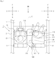
- FIG. 1 is a plan view showing an interior of a vehicle to which an inflated far side airbag according to an example of the current disclosure is applied and
- FIG. 2 is a side view showing the configuration of the inflated far side airbag according to an example of the current disclosure.
- a far side airbag apparatus 100 is installed in a backrest of a vehicle seat.
- the vehicle seat may be disposed, for example, on the left and right sides with respect to the inner center C of the vehicle when viewed in the width direction of the vehicle.
- a driver seat 10 is arranged on the left side of the vehicle
- a passenger seat 30 is arranged on the right side of the vehicle with respect to the inner center C of the vehicle.
- the far side airbag apparatus 100 is installed inside a backrest 31 of the passenger seat 30.
- the far side airbag apparatus 100 may be installed inside a backrest 11 of the driver seat 10 while being directed toward the center of the vehicle.
- the far side airbag apparatus 100 may be installed in the driver seat 10 and the passenger seat 30 in order to selectively operate in accordance with the side collision or oblique side collision of the vehicle.
- the far side airbag apparatus 100 is configured to operate from the seat opposite to the collision side of the vehicle to prevent a passenger seated on a side opposite to collision side from moving toward the collision side. Especially, the far side airbag apparatus 100 according to the present disclosure is configured to prevent the passenger seated on a side opposite to the collision side from moving toward the inner center and the outside of the vehicle upon the oblique side collision caused when an object collides with a side of the vehicle at a predetermined angle.
- the far side airbag apparatus 100 includes an inflator 101 serving as a gas generator and a far side airbag 110 which is inflated and deployed by receiving gas supplied from the inflator 101.
- the inflator 101 is coupled to a frame 13 of the backrest 31 of the passenger seat 30 via a fastening member 5 and is connected to the rear of the far side airbag 110.
- the far side airbag 110 is received inside the backrest 31 in a folded state together with the inflator 101.
- a rear end of the far side airbag 110 connected to the inflator 101 is supported inside the backrest 31.
- the far side airbag 110 has a cantilever shape in which the rear end of the far side airbag 110 is supported by the frame 13 of the backrest 31 and the front end of the far side airbag 110 protrudes forward of the vehicle.
- the far side airbag 110 includes an inner portion 111 facing the passenger and an outer portion 113 facing the inner center of the vehicle when inflated.
- the inner portion 111 and the outer portion 113 may be fabricated by using separate fabrics and connected to each other through a sewing line.
- the inner portion 111 and the outer portion 113 of the far side airbag 110 may be formed of a single fabric.
- the far side airbag 110 includes a main inflating portion 115 for protecting a shoulder portion, a chest portion, and an abdominal portion of the passenger and an upper inflating portion 117 extending upward from the main inflating portion 115 to protect a head portion of the passenger.
- the far side airbag 110 may further include a pelvic inflating portion that protects the pelvis of the passenger.
- the main inflating portion 115 and the upper inflating portion 117 may be formed of separate fabrics and connected to each other. In another embodiment, the main inflating portion 115 and the upper inflating portion 117 may be formed of a single fabric.
- the inner portion 111 of the far side airbag 110 When inflated, the inner portion 111 of the far side airbag 110 is inclined such that the inner portion 111 is gradually closer to the side of the vehicle in the forward direction F of the vehicle, thereby preventing the passenger seated on a side opposite to the collision side from falling out of the protection range of the far side airbag 110 upon the oblique side collision of the vehicle by restraining the passenger from moving toward the front portion and the center of the vehicle, for example, while sliding along a front end of the far side airbag 110.
- the passenger 02 seated on the passenger seat 30 can be effectively prevented from moving toward the front portion and the inner center of the vehicle.
- the passenger O2 seated on the passenger seat 30 moves in the forward direction F of the vehicle as well as toward the inner center C of the vehicle.
- the inner portion 111 of the far side airbag 110 is inclined in the forward direction F and the outward direction 0 of the vehicle, when the passenger O2 seated on the passenger seat 30 obliquely moves in the forward direction F of the vehicle F and toward the inner center C of the vehicle, the inner portion 111 supports the passenger O2 in the outward direction of the vehicle.
- the passenger O2 can be prevented from moving out of the protection range of the far side airbag 110 so that the risk of collision between two passengers O1 and O2 seated on the driver seat 10 and the passenger seat 30, respectively, may be reduced.
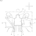
- FIG. 3 is a front view taken along an arrow III of FIG. 1 .
- the main inflating portion 115 of the far side airbag 110 is configured to have an expansion thickness T1 substantially equal to the distance between the driver seat 10 and the passenger seat 30, and the upper inflating portion 117 is configured to have an expansion thickness T2 smaller than the expansion thickness T1 of the main inflating portion 115. That is, the front side of the far side airbag 110 may have a T shape rotated by about 180 degrees.
- the far side airbag 110 can restrain the shoulder portion and the chest portion of the passenger O2 seated on the passenger seat 30 at the early stage of inflation of the far side airbag, thereby preventing the risk of collision between the two passengers 01 and O2.
- the upper inflating portion 117 Since the main inflating portion 115 can restrain the two passengers O1 and O2 at the early stage of inflation, the upper inflating portion 117 does not need to have the expansion thickness equal to the expansion thickness T1 of the main inflating portion 115, so the upper inflating portion 117 is configured to have the expansion thickness T2 smaller than the expansion thickness T1. Due to the above configuration, the airbag deployment speed can be improved and the head, shoulders, chest, and abdomen of the passenger can be properly protected.
- the far side airbag 110 may further include a reinforcing structure for increasing the supporting strength.
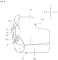
- FIG. 4a is a side view showing the inflated state of the far side airbag having a reinforcing panel according to another example of the current disclosure.
- the far side airbag 100 may further include a reinforcing panel 118 connected to a rear side of the far side airbag 100.
- the reinforcing panel 118 may be connected to the rear end of the far side airbag 100 and the other end may be fixed to the frame 13 in the backrest 31 of the passenger seat 30.
- the reinforcing panel 118 may have a length extending in the forward direction F to partially surround a rear chamber portion 115 of the far side airbag 110.
- the reinforcing panel 118 may be configured to partially overlap the rear outer surface of the inner portion 111 or the outer portion 113 of the far side airbag 110.
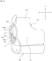
- FIG. 4b is a view showing the configuration of a tether member of the far side airbag apparatus according to another example of the current disclosure.
- the far side airbag 110 may include at least one tether member 130 disposed inside or outside the far side airbag 110.
- the tether member 130 may include a first tether member 131 having one end 131a fixed to the frame 13 and the other end 131b connected to the front portion of the far side airbag 110.
- the other end 131b of the first tether member 131 may be connected to the front portion of the far side airbag 110 by a sewing line S1.
- the first tether member 131 is configured to cross the front and rear directions of the far side airbag 110 so that, when the far side airbag 110 is inflated and deployed, the front end of the far side airbag 110 can be guided to deploy in the forward direction F from the backrest 11.
- FIG. 4c is a view showing the configuration of another tether member of the far side airbag apparatus according to another example of the current disclosure.
- the tether member 130 may further include a second tether member 133 in addition to the first tether member 131 shown in FIG. 4b .
- the second tether member 133 may have a first end 133a connected to the frame 13 by a fastening member 5 that connects the inflator 101 to the frame 13, and the other end 133b connected to the far side airbag 110, for example, connected to the center of the far side airbag 110.
- the other end 133b of the second tether member 133 may be connected to the far side airbag 110 by a sewing line S2.
- FIG. 4d is a view showing the configuration of still another tether member of a far side airbag apparatus according to another example of the current disclosure.
- the tether member 130 may include a third tether member 135 having one end 135a fixed to the frame 13 together with the inflator 101 by the fastening member 5 that connects the inflator 101 to the frame 13, and the other end 135b connected to the reinforcing panel 118.
- the other end 135b of the third tether member 135 may be connected to the reinforcing panel 118 by a sewing line S3.
- the far side airbag 110 Since the rear side of the far side airbag 110 is fixed to the frame 13 in a plan view, the far side airbag 110 forms a cantilever when it is deployed.
- the far side airbag 110 is rotated in the counterclockwise direction about a portion fixed to the frame 13, so that the restraining force to the passenger may be lowered (see FIG. 1 ).
- the reinforcing panel 118 and the tether member 130 are provided to increase the supporting strength of the far side airbag 110, thereby enhancing the passenger protection effect.
- one sides of the reinforcing panel 118 and the tether member 130 are supported by the frame 130 and the other sides of the reinforcing panel 118 and the tether member 130 are connected to the far side airbag 110 so that, when the passenger O1 collides with the far side airbag 110, the reinforcing panel 118 and the tether member 130 provide tension against the rotational force of the far side airbag 110 that rotates about the portion fixed to the frame, thereby preventing the far side airbag 110 from rotating.
- the passenger restraining effect can be enhanced.
- one end of the reinforcing panel 118 is connected to the rear side of the far side airbag 118 and the other end is fixed to the frame 13.
- one sides 131a, 133a and 135b of the first to third tether members 131, 133 and 135 are fixed to the frame 13 and the other sides 131b, 133b and 135b are fixed to the far side airbag 110.
- the rear side of the far side airbag 110 is pushed toward the frame 13 by the first to third tether members 131, 133 and 135 and the rear end thereof is restrained by the reinforcing panel 118.
- the far side airbag device 10 of the present disclosure can effectively prevent the passenger from moving toward the center C of the vehicle in the width direction of the vehicle.
- the tether member 130 may be provided inside the far side airbag 110.
- the coupling scheme for the tether member 130 may be similar to the coupling scheme for the tether members 131, 133, and 15 described above.
- FIG. 5 is a plan view showing an interior of a vehicle to which an inflated far side airbag according to another example of the current disclosure is applied.
- the same reference numerals will be assigned to the same components, and redundant description will be omitted.
- the far side airbag 110 includes a front protrusion 116 which is provided at a front end of the far side airbag 110 and protrudes in the outward direction O of the vehicle.
- the inflator 101 installed in the backrest 31 of the passenger seat 30 is operated to generate gas and the gas generated from the inflator 101 inflates the far side airbag 110.
- the front protrusion 116 provided at the front end of the far side airbag 110 further protrudes in the outward direction O of the vehicle to support the front side of the passenger O2.
- the passenger O2 seated on the passenger seat 30 is restrained by the inner portion 111 and the front protrusion 116 of the far side airbag 110 so that the passenger O2 can be prevented from moving in the forward direction F and toward the center C of the vehicle.
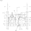
- FIG. 6 is a plan view showing an interior of a vehicle to which an inflated far side airbag according to an embodiment of the present invention is applied.
- the far side airbag 110 is provided at a front end thereof with the front protrusion 116 for supporting a front portion of the passenger 02 seated on the passenger seat 30, and an inclination portion 112, which is formed by inclining the inner portion 111 of the far side airbag 110, is formed between the front protrusion 116 and the inflator 101.
- the passenger O2 seated on the passenger seat 30 moves in the forward direction and toward the center C of the vehicle caused by the left oblique collision of the vehicle, the passenger O2 may be surrounded and restrained by the inclination portion 112 and the front protrusion 116 of the far side airbag 110. As a result, the collision between the two passengers O1 and O2 can be prevented.
- the far side airbag apparatus 100 shown in FIGS. 5 and 6 may further include the configuration of the reinforcing panel 118 and the tether member 130 as described above.
Landscapes
- Engineering & Computer Science (AREA)
- Mechanical Engineering (AREA)
- Aviation & Aerospace Engineering (AREA)
- Transportation (AREA)
- Physics & Mathematics (AREA)
- Fluid Mechanics (AREA)
- Air Bags (AREA)
Claims (7)
- Véhicule ayant un dispositif de coussin gonflable côté latéral (100) et au moins deux dossiers (11, 31), le dispositif de coussin gonflable côté latéral (100) comprenant :
un coussin gonflable côté latéral (110) installé sur un côté d'un cadre (13) d'un dossier (31) dirigé vers une partie centrale intérieure (C) du véhicule de telle sorte que le coussin gonflable côté latéral (110) soit dilaté et déployé entre les au moins deux dossiers (11, 31) disposés dans un sens de la largeur du véhicule, et comportant une partie intérieure (111) dirigée vers un passager (O2) assis sur un côté opposé à un côté collision du véhicule lors de la dilatation et une partie extérieure (113) dirigée vers la partie centrale intérieure (C) du véhicule lors de la dilatation, dans lequel, lors d'une collision de véhicule, la partie intérieure (111) soutient le passager (O2) assis sur le côté du côté collision du véhicule vers une partie extérieure (O) du véhicule pour empêcher le passager (O2) de se déplacer vers la partie centrale intérieure (C) et une partie avant (F) du véhicule, et dans lequel la partie intérieure (111) du coussin gonflable côté latéral (110) comporte une partie saillante avant (116) faisant saillie vers l'extérieur depuis une partie avant du coussin gonflable côté latéral (110), la partie intérieure (111) du coussin gonflable côté latéral (110) étant inclinée vers la partie avant (F) et la partie extérieure (O) du véhicule. - Véhicule selon la revendication 1, dans lequel la partie intérieure (111) du coussin gonflable côté latéral (110) comporte :une partie d'inclinaison (112) inclinée plus près de la partie extérieure (O) du véhicule dans une direction avant (F) du véhicule lors de la dilatation ; etdans lequel la partie saillante avant (116) fait saillie vers la partie extérieure du véhicule depuis une partie avant de la partie d'inclinaison (112).
- Véhicule selon la revendication 1, dans lequel le coussin gonflable côté latéral (110) a une épaisseur de dilatation (T1) correspondant à une largeur entre un siège conducteur (10) et un siège passager (30) du véhicule.
- Véhicule selon l'une des revendications 1, comprenant en outre :un panneau de renforcement (118) ayant un côté relié à un côté arrière du coussin gonflable côté latéral (110) et un côté opposé fixé au cadre (13) du dossier (31) ; etau moins un élément d'attache (130) installé à l'intérieur ou à l'extérieur du coussin gonflable côté latéral (110) et ayant une extrémité (131b, 133b, 135b) reliée au coussin gonflable côté latéral (110) et une extrémité opposée (131a, 133a, 135a) reliée à proximité d'une partie de fixation du côté arrière du coussin gonflable côté latéral (110).
- Véhicule selon la revendication 4, dans lequel l'extrémité opposée (131a, 133a, 135a) de l'élément d'attache (130) est reliée au châssis (13) du dossier (31).
- Véhicule selon la revendication 4, dans lequel l'extrémité opposée (131a, 133a, 135a) de l'élément d'attache (129) est reliée au panneau de renforcement (118).
- Véhicule selon la revendication 5, comprenant en outre un gonfleur (101) fixé au châssis (13) à travers un élément de fixation (5) pour fournir du gaz au coussin gonflable côté latéral (110), dans lequel l'extrémité opposée (131a, 133a, 135a) de l'élément d'attache (130) est reliée au cadre (13) avec le gonfleur (101) par l'élément de fixation (5).
Applications Claiming Priority (2)
| Application Number | Priority Date | Filing Date | Title |
|---|---|---|---|
| KR1020160045893A KR101781387B1 (ko) | 2016-04-15 | 2016-04-15 | 자동차의 파 사이드 에어백 장치 |
| PCT/KR2017/003470 WO2017179839A1 (fr) | 2016-04-15 | 2017-03-30 | Appareil de coussin de sécurité gonflable de côté éloigné pour véhicule |
Publications (3)
| Publication Number | Publication Date |
|---|---|
| EP3444148A1 EP3444148A1 (fr) | 2019-02-20 |
| EP3444148A4 EP3444148A4 (fr) | 2019-11-13 |
| EP3444148B1 true EP3444148B1 (fr) | 2021-06-09 |
Family
ID=60035171
Family Applications (1)
| Application Number | Title | Priority Date | Filing Date |
|---|---|---|---|
| EP17782594.0A Active EP3444148B1 (fr) | 2016-04-15 | 2017-03-30 | Appareil de coussin de sécurité gonflable de côté éloigné pour véhicule |
Country Status (5)
| Country | Link |
|---|---|
| US (1) | US11066036B2 (fr) |
| EP (1) | EP3444148B1 (fr) |
| JP (1) | JP2019511414A (fr) |
| KR (1) | KR101781387B1 (fr) |
| WO (1) | WO2017179839A1 (fr) |
Families Citing this family (58)
| Publication number | Priority date | Publication date | Assignee | Title |
|---|---|---|---|---|
| DE102015016347A1 (de) * | 2015-12-17 | 2017-06-22 | Autoliv Development Ab | Airbagvorrichtung für ein Kraftfahrzeug, sowie Airbagkissen für eine Airbagvorrichtung |
| KR101807659B1 (ko) * | 2016-07-28 | 2017-12-12 | 아우토리브 디벨롭먼트 아베 | 자동차의 파 사이드 에어백 장치 |
| DE102016010249A1 (de) * | 2016-08-26 | 2018-03-01 | Autoliv Development Ab | Airbagvorrichtung für ein Kraftfahrzeug, sowie Airbagkissen für eine Airbagvorrichtung |
| KR102530685B1 (ko) * | 2017-08-18 | 2023-05-11 | 현대자동차주식회사 | 차량용 에어백 |
| KR102452467B1 (ko) | 2017-08-24 | 2022-10-11 | 현대자동차주식회사 | 차량용 에어백 |
| KR102399622B1 (ko) | 2017-08-24 | 2022-05-17 | 현대자동차주식회사 | 차량의 사이드 에어백 장치 |
| DE102017218338A1 (de) * | 2017-10-13 | 2019-04-18 | Bayerische Motoren Werke Aktiengesellschaft | Airbag-anordnung für einen fahrzeugsitz eines kraftfahrzeugs |
| WO2019107073A1 (fr) * | 2017-11-30 | 2019-06-06 | オートリブ ディベロップメント エービー | Dispositif de retenue de passager |
| JP6915561B2 (ja) | 2018-02-14 | 2021-08-04 | 豊田合成株式会社 | ファーサイドエアバッグ装置 |
| KR102565349B1 (ko) | 2018-03-19 | 2023-08-14 | 현대자동차주식회사 | 차량용 에어백 |
| KR102064842B1 (ko) * | 2018-05-01 | 2020-01-10 | 아우토리브 디벨롭먼트 아베 | 자동차의 에어백 장치 |
| EP3815989A4 (fr) * | 2018-06-26 | 2021-11-03 | Autoliv Development AB | Coussin de sécurité gonflable de côté éloigné |
| CN112533798B (zh) * | 2018-08-14 | 2022-12-20 | 奥托立夫开发公司 | 侧面安全气囊装置 |
| US11091113B2 (en) * | 2018-09-24 | 2021-08-17 | Zoox, Inc. | Vehicle side airbag |
| JP7271378B2 (ja) * | 2018-10-24 | 2023-05-11 | オートリブ ディベロップメント エービー | サイドエアバッグ装置 |
| EP3643566B1 (fr) * | 2018-10-24 | 2021-06-09 | Autoliv Development AB | Dispositif d'airbag latéral |
| US20200189513A1 (en) * | 2018-12-14 | 2020-06-18 | Key Safety Systems, Inc. | Far side crash mitigation |
| FR3092296B1 (fr) * | 2019-02-06 | 2021-01-08 | Psa Automobiles Sa | Dispositif de retenue anti-basculement de siège, pour un véhicule |
| JP7165095B2 (ja) * | 2019-03-29 | 2022-11-02 | 株式会社Subaru | 乗員保護装置 |
| JP7283943B2 (ja) | 2019-03-29 | 2023-05-30 | 株式会社Subaru | 乗員保護装置 |
| DE102019112344B4 (de) * | 2019-05-10 | 2025-02-27 | Autoliv Development Ab | Fahrzeugsitzanordnung |
| CN111976644B (zh) * | 2019-05-21 | 2022-10-14 | 奥托立夫开发公司 | 安全气囊装置 |
| JP7372862B2 (ja) * | 2019-05-21 | 2023-11-01 | オートリブ ディベロップメント エービー | エアバッグ装置 |
| EP3792119B1 (fr) * | 2019-09-16 | 2022-09-14 | Autoliv Development AB | Système d'airbag de véhicule |
| JP7243552B2 (ja) | 2019-09-26 | 2023-03-22 | 豊田合成株式会社 | ファーサイドエアバッグ装置 |
| KR102789237B1 (ko) * | 2019-12-17 | 2025-03-28 | 현대모비스 주식회사 | 차량용 에어백 장치 |
| EP3838688B1 (fr) * | 2019-12-20 | 2024-06-12 | Autoliv Development AB | Dispositif d'airbag latéral |
| JP7510326B2 (ja) * | 2019-12-20 | 2024-07-03 | オートリブ ディベロップメント エービー | サイドエアバッグ装置 |
| JP7205500B2 (ja) * | 2020-01-08 | 2023-01-17 | 豊田合成株式会社 | ファーサイドエアバッグ装置 |
| US11203319B2 (en) * | 2020-01-14 | 2021-12-21 | Ford Global Technologies, Llc | Airbag inflation restraint with releasable extension |
| US11214222B2 (en) * | 2020-01-22 | 2022-01-04 | ZF Passive Safety Systems US Inc. | Occupant restraint system |
| JP7606350B2 (ja) | 2020-03-13 | 2024-12-25 | オートリブ ディベロップメント エービー | エアバッグ装置の製造方法及びエアバッグ装置。 |
| JP7532065B2 (ja) * | 2020-03-30 | 2024-08-13 | マツダ株式会社 | サイドエアバッグ装置 |
| KR102387635B1 (ko) | 2020-05-12 | 2022-04-18 | 아우토리브 디벨롭먼트 아베 | 자동차의 파 사이드 에어백 장치 |
| KR102388323B1 (ko) | 2020-05-22 | 2022-04-20 | 아우토리브 디벨롭먼트 아베 | 자동차의 파 사이드 에어백 장치 |
| KR102396754B1 (ko) | 2020-06-09 | 2022-05-12 | 아우토리브 디벨롭먼트 아베 | 자동차의 파 사이드 에어백 장치 |
| KR102872965B1 (ko) * | 2020-08-12 | 2025-10-16 | 현대자동차주식회사 | 사이드 에어백 장치 |
| KR102454236B1 (ko) | 2020-09-08 | 2022-10-17 | 아우토리브 디벨롭먼트 아베 | 자동차의 에어백 장치 |
| KR102472829B1 (ko) | 2020-09-09 | 2022-12-02 | 아우토리브 디벨롭먼트 아베 | 자동차의 에어백 장치 |
| KR20220036245A (ko) | 2020-09-15 | 2022-03-22 | 현대모비스 주식회사 | 차량용 시트 에어백 시스템 및 이의 제어방법 |
| KR102896021B1 (ko) | 2020-10-15 | 2025-12-03 | 현대모비스 주식회사 | 차량용 에어백 시스템 및 이의 제어 방법 |
| JP7613177B2 (ja) * | 2021-03-17 | 2025-01-15 | トヨタ自動車株式会社 | 助手席用エアバッグ装置 |
| KR20220130525A (ko) | 2021-03-18 | 2022-09-27 | 아우토리브 디벨롭먼트 아베 | 자동차의 파 사이드 에어백 장치 |
| JP7543986B2 (ja) | 2021-06-09 | 2024-09-03 | トヨタ自動車株式会社 | シート搭載型エアバッグ装置 |
| JP2022188683A (ja) | 2021-06-09 | 2022-12-21 | トヨタ自動車株式会社 | シート搭載型エアバッグ装置 |
| JP7533385B2 (ja) | 2021-07-07 | 2024-08-14 | トヨタ自動車株式会社 | 車両用乗員保護装置 |
| KR102614108B1 (ko) | 2021-07-08 | 2023-12-15 | 아우토리브 디벨롭먼트 아베 | 자동차의 에어백 하우징 |
| KR102626944B1 (ko) | 2021-08-11 | 2024-01-19 | 아우토리브 디벨롭먼트 아베 | 자동차의 파 사이드 에어백 장치 및 그의 폴딩 방법 |
| JP7574769B2 (ja) | 2021-08-27 | 2024-10-29 | トヨタ自動車株式会社 | 車両用エアバッグ装置 |
| KR102779058B1 (ko) | 2022-12-22 | 2025-03-12 | 아우토리브 디벨롭먼트 아베 | 자동차의 파 사이드 에어백 장치 |
| KR102781300B1 (ko) | 2022-12-22 | 2025-03-17 | 아우토리브 디벨롭먼트 아베 | 자동차의 파 사이드 에어백 장치 |
| JP7764849B2 (ja) * | 2022-12-26 | 2025-11-06 | トヨタ自動車株式会社 | 車両用乗員拘束装置及びファーサイドエアバッグ折り畳み方法 |
| JP7800479B2 (ja) * | 2023-02-24 | 2026-01-16 | トヨタ自動車株式会社 | 車両用センターエアバッグ装置 |
| KR102839904B1 (ko) | 2023-06-12 | 2025-07-29 | 아우토리브 디벨롭먼트 아베 | 자동차의 사이드 에어백 장치 |
| US12043202B1 (en) * | 2023-06-16 | 2024-07-23 | Ford Global Technologies, Llc | Seat airbag with pyrotechnic retractor |
| DE102023125458A1 (de) * | 2023-09-20 | 2025-03-20 | Zf Automotive Germany Gmbh | Gassack eines fahrzeuginsassenrückhaltesystems und fahrzeuginsassenrückhaltesystem |
| KR20260007900A (ko) * | 2024-07-08 | 2026-01-15 | 현대모비스 주식회사 | 에어백 장치 |
| CN223116317U (zh) * | 2024-07-30 | 2025-07-18 | 奥托立夫开发公司 | 安全气囊和安全气囊组件 |
Family Cites Families (46)
| Publication number | Priority date | Publication date | Assignee | Title |
|---|---|---|---|---|
| US5499840A (en) * | 1994-03-31 | 1996-03-19 | Ikeda Bussan Co., Ltd. | Automotive seat with air-bag |
| JP3456754B2 (ja) * | 1994-06-14 | 2003-10-14 | 本田技研工業株式会社 | 車両用エアバッグの展開方法 |
| US5730464A (en) * | 1995-08-11 | 1998-03-24 | General Motors Corporation | Air bag module with tether |
| GB2378424B (en) * | 2001-08-07 | 2004-06-23 | Autoliv Dev | Improvements in or relating to an airbag arrangement |
| EP1470969A1 (fr) * | 2003-04-24 | 2004-10-27 | Autoliv Development AB | Système d'airbag |
| US7549672B2 (en) * | 2004-05-27 | 2009-06-23 | Toyoda Gosei Co., Ltd. | Side airbag device |
| DE102005025553A1 (de) * | 2005-06-01 | 2006-12-07 | Autoliv Development Ab | Airbaganordnung |
| DE102005059197B4 (de) * | 2005-12-06 | 2008-04-10 | Takata-Petri Ag | Fahrzeuginsassen-Rückhaltesysteme mit einem in einem Fahrzeugsitz angeordneten aufblasbaren Gassack |
| JP2008080919A (ja) | 2006-09-27 | 2008-04-10 | Takata Corp | 乗員拘束装置 |
| JP5382584B2 (ja) | 2007-09-14 | 2014-01-08 | トヨタ自動車東日本株式会社 | エアバッグ装置 |
| JP5382585B2 (ja) * | 2007-09-14 | 2014-01-08 | トヨタ自動車東日本株式会社 | エアバッグ |
| US8353529B2 (en) * | 2007-09-16 | 2013-01-15 | Toyota Motor East Japan, Inc. | Airbag apparatus |
| JP2010076640A (ja) * | 2008-09-26 | 2010-04-08 | Toyoda Gosei Co Ltd | エアバッグ装置 |
| KR101509780B1 (ko) * | 2009-07-31 | 2015-04-08 | 현대자동차주식회사 | 차량용 사이드에어백 유닛 |
| DE102010027401B4 (de) * | 2010-07-15 | 2022-05-12 | Autoliv Development Ab | Seitengassack mit seitlicher Abstützung |
| US8282126B2 (en) * | 2010-10-13 | 2012-10-09 | Tk Holdings Inc. | Occupant restraint system |
| KR101355594B1 (ko) * | 2011-12-07 | 2014-01-29 | 현대자동차주식회사 | 차량용 듀얼 챔버 사이드에어백 장치 |
| EP2810831B1 (fr) * | 2012-02-01 | 2018-05-09 | Toyota Jidosha Kabushiki Kaisha | Dispositif de coussin de sécurité gonflable latéral de véhicule |
| JP5853916B2 (ja) * | 2012-09-13 | 2016-02-09 | 豊田合成株式会社 | エアバッグ装置 |
| JP2014076702A (ja) * | 2012-10-09 | 2014-05-01 | Toyota Motor Corp | 車両用乗員保護装置 |
| JP5803989B2 (ja) * | 2013-06-25 | 2015-11-04 | トヨタ自動車株式会社 | ルーフエアバッグ装置及び乗員保護装置 |
| EP3072751B1 (fr) * | 2013-11-21 | 2018-03-21 | Toyota Jidosha Kabushiki Kaisha | Dispositif de coussin de sécurité gonflable latéral de véhicule |
| JP5949737B2 (ja) | 2013-12-06 | 2016-07-13 | トヨタ自動車株式会社 | 車両用ファーサイドエアバッグ装置 |
| JP5895014B2 (ja) | 2014-03-28 | 2016-03-30 | 富士重工業株式会社 | エアバッグ装置 |
| US9415739B2 (en) * | 2014-04-22 | 2016-08-16 | Tk Holdings Inc. | Mounting device for an airbag module |
| JP6356788B2 (ja) * | 2014-04-30 | 2018-07-11 | オートリブ ディベロップメント エービー | 車両用サイドエアバッグ装置 |
| JP6179469B2 (ja) * | 2014-06-23 | 2017-08-16 | トヨタ自動車株式会社 | ファーサイドエアバッグ装置 |
| JP6107749B2 (ja) * | 2014-06-23 | 2017-04-05 | トヨタ自動車株式会社 | サイドエアバッグ装置 |
| US9505369B2 (en) * | 2014-09-12 | 2016-11-29 | Toyoda Gosei Co., Ltd. | Side airbag apparatus |
| JP6149840B2 (ja) * | 2014-10-21 | 2017-06-21 | トヨタ自動車株式会社 | 車両用ファーサイドエアバッグ装置 |
| JP6149849B2 (ja) * | 2014-11-25 | 2017-06-21 | トヨタ自動車株式会社 | 車両用ファーサイドエアバッグ装置 |
| JP6183342B2 (ja) * | 2014-12-03 | 2017-08-23 | トヨタ自動車株式会社 | 車両用乗員保護装置 |
| US9428135B1 (en) * | 2015-02-10 | 2016-08-30 | GM Global Technology Operations LLC | Two front center airbag |
| KR101708213B1 (ko) * | 2015-07-22 | 2017-02-20 | 아우토리브 디벨롭먼트 아베 | 측면 충돌용 에어백 |
| JP6447432B2 (ja) * | 2015-09-11 | 2019-01-09 | トヨタ自動車株式会社 | ファーサイドエアバッグ装置及び車両用シート |
| JP6632354B2 (ja) * | 2015-12-03 | 2020-01-22 | Joyson Safety Systems Japan株式会社 | エアバッグ及びエアバッグ装置 |
| DE102015016347A1 (de) * | 2015-12-17 | 2017-06-22 | Autoliv Development Ab | Airbagvorrichtung für ein Kraftfahrzeug, sowie Airbagkissen für eine Airbagvorrichtung |
| JP6271622B2 (ja) * | 2016-03-18 | 2018-01-31 | 株式会社Subaru | エアバッグ装置 |
| KR102547636B1 (ko) * | 2016-05-20 | 2023-06-26 | 현대모비스 주식회사 | 차량용 에어백장치 |
| KR101807659B1 (ko) * | 2016-07-28 | 2017-12-12 | 아우토리브 디벨롭먼트 아베 | 자동차의 파 사이드 에어백 장치 |
| DE102016010249A1 (de) * | 2016-08-26 | 2018-03-01 | Autoliv Development Ab | Airbagvorrichtung für ein Kraftfahrzeug, sowie Airbagkissen für eine Airbagvorrichtung |
| US10407015B2 (en) * | 2017-06-27 | 2019-09-10 | Ford Global Technologies, Llc | Restraint system |
| JP6670510B2 (ja) * | 2018-03-30 | 2020-03-25 | 株式会社Subaru | 車両の乗員保護装置 |
| US10752198B2 (en) * | 2018-07-13 | 2020-08-25 | Ford Global Technologies, Llc | Vehicle airbag |
| KR102505747B1 (ko) * | 2018-08-07 | 2023-03-03 | 현대모비스 주식회사 | 파사이드 에어백 장치의 폴딩방법 |
| US10773678B2 (en) * | 2018-08-21 | 2020-09-15 | Honda Motor Co., Ltd. | Side impact occupant restraint airbag module |
-
2016
- 2016-04-15 KR KR1020160045893A patent/KR101781387B1/ko active Active
-
2017
- 2017-03-30 EP EP17782594.0A patent/EP3444148B1/fr active Active
- 2017-03-30 JP JP2018550397A patent/JP2019511414A/ja active Pending
- 2017-03-30 US US16/092,250 patent/US11066036B2/en active Active
- 2017-03-30 WO PCT/KR2017/003470 patent/WO2017179839A1/fr not_active Ceased
Non-Patent Citations (1)
| Title |
|---|
| None * |
Also Published As
| Publication number | Publication date |
|---|---|
| JP2019511414A (ja) | 2019-04-25 |
| US11066036B2 (en) | 2021-07-20 |
| KR101781387B1 (ko) | 2017-09-25 |
| WO2017179839A1 (fr) | 2017-10-19 |
| US20190161053A1 (en) | 2019-05-30 |
| EP3444148A4 (fr) | 2019-11-13 |
| EP3444148A1 (fr) | 2019-02-20 |
Similar Documents
| Publication | Publication Date | Title |
|---|---|---|
| EP3444148B1 (fr) | Appareil de coussin de sécurité gonflable de côté éloigné pour véhicule | |
| EP3492323B1 (fr) | Dispositif de coussin de sécurité gonflable côté éloigné de véhicule | |
| EP3326870B1 (fr) | Vehicule avec coussin gonflable de sécurité protégeant contre un choc latéral | |
| US12337784B2 (en) | Airbag device and vehicle seat | |
| KR102387636B1 (ko) | 승차인 보호 장치 | |
| KR101014124B1 (ko) | 차량의 운전석 에어백쿠션 구조 | |
| KR101739857B1 (ko) | 측면 충돌용 에어백 | |
| KR102403511B1 (ko) | 에어백 장치 | |
| US10723303B2 (en) | Vehicle curtain airbag device | |
| WO2018179850A1 (fr) | Dispositif de protection de passager | |
| JP7568834B2 (ja) | サイドエアバッグ装置 | |
| JP2011037398A (ja) | 運転席用エアバッグ | |
| JP2018058552A (ja) | 車両用カーテンエアバッグ装置 | |
| JP2019059381A (ja) | ファーサイドエアバッグ装置 | |
| EP4159552A1 (fr) | Dispositif de coussin de sécurité gonflable | |
| CN115214518B (zh) | 远侧气囊装置 | |
| JP7589669B2 (ja) | エアバッグ装置 | |
| CN116198446A (zh) | 远侧气囊装置 | |
| WO2020110586A1 (fr) | Dispositif de coussin de sécurité gonflable latéral | |
| US11260819B2 (en) | Airbag apparatus | |
| CN114802086B (zh) | 远侧气囊装置 | |
| JP7494807B2 (ja) | ファーサイドエアバッグ装置 | |
| US12269409B2 (en) | Airbag device | |
| US20240198951A1 (en) | Side airbag device | |
| KR20260055887A (ko) | 자동차의 파 사이드 에어백 장치 |
Legal Events
| Date | Code | Title | Description |
|---|---|---|---|
| STAA | Information on the status of an ep patent application or granted ep patent |
Free format text: STATUS: THE INTERNATIONAL PUBLICATION HAS BEEN MADE |
|
| PUAI | Public reference made under article 153(3) epc to a published international application that has entered the european phase |
Free format text: ORIGINAL CODE: 0009012 |
|
| STAA | Information on the status of an ep patent application or granted ep patent |
Free format text: STATUS: REQUEST FOR EXAMINATION WAS MADE |
|
| 17P | Request for examination filed |
Effective date: 20181010 |
|
| AK | Designated contracting states |
Kind code of ref document: A1 Designated state(s): AL AT BE BG CH CY CZ DE DK EE ES FI FR GB GR HR HU IE IS IT LI LT LU LV MC MK MT NL NO PL PT RO RS SE SI SK SM TR |
|
| AX | Request for extension of the european patent |
Extension state: BA ME |
|
| DAV | Request for validation of the european patent (deleted) | ||
| DAX | Request for extension of the european patent (deleted) | ||
| A4 | Supplementary search report drawn up and despatched |
Effective date: 20191015 |
|
| RIC1 | Information provided on ipc code assigned before grant |
Ipc: B60R 21/00 20060101ALI20191009BHEP Ipc: B60R 21/2338 20110101ALI20191009BHEP Ipc: B60R 21/264 20060101ALI20191009BHEP Ipc: B60N 2/64 20060101ALI20191009BHEP Ipc: B60R 21/231 20110101AFI20191009BHEP |
|
| STAA | Information on the status of an ep patent application or granted ep patent |
Free format text: STATUS: EXAMINATION IS IN PROGRESS |
|
| 17Q | First examination report despatched |
Effective date: 20200707 |
|
| GRAP | Despatch of communication of intention to grant a patent |
Free format text: ORIGINAL CODE: EPIDOSNIGR1 |
|
| STAA | Information on the status of an ep patent application or granted ep patent |
Free format text: STATUS: GRANT OF PATENT IS INTENDED |
|
| INTG | Intention to grant announced |
Effective date: 20210316 |
|
| GRAS | Grant fee paid |
Free format text: ORIGINAL CODE: EPIDOSNIGR3 |
|
| GRAA | (expected) grant |
Free format text: ORIGINAL CODE: 0009210 |
|
| STAA | Information on the status of an ep patent application or granted ep patent |
Free format text: STATUS: THE PATENT HAS BEEN GRANTED |
|
| AK | Designated contracting states |
Kind code of ref document: B1 Designated state(s): AL AT BE BG CH CY CZ DE DK EE ES FI FR GB GR HR HU IE IS IT LI LT LU LV MC MK MT NL NO PL PT RO RS SE SI SK SM TR |
|
| REG | Reference to a national code |
Ref country code: GB Ref legal event code: FG4D |
|
| REG | Reference to a national code |
Ref country code: CH Ref legal event code: EP Ref country code: AT Ref legal event code: REF Ref document number: 1400212 Country of ref document: AT Kind code of ref document: T Effective date: 20210615 |
|
| REG | Reference to a national code |
Ref country code: DE Ref legal event code: R096 Ref document number: 602017040057 Country of ref document: DE |
|
| REG | Reference to a national code |
Ref country code: IE Ref legal event code: FG4D |
|
| REG | Reference to a national code |
Ref country code: LT Ref legal event code: MG9D |
|
| PG25 | Lapsed in a contracting state [announced via postgrant information from national office to epo] |
Ref country code: BG Free format text: LAPSE BECAUSE OF FAILURE TO SUBMIT A TRANSLATION OF THE DESCRIPTION OR TO PAY THE FEE WITHIN THE PRESCRIBED TIME-LIMIT Effective date: 20210909 Ref country code: HR Free format text: LAPSE BECAUSE OF FAILURE TO SUBMIT A TRANSLATION OF THE DESCRIPTION OR TO PAY THE FEE WITHIN THE PRESCRIBED TIME-LIMIT Effective date: 20210609 Ref country code: FI Free format text: LAPSE BECAUSE OF FAILURE TO SUBMIT A TRANSLATION OF THE DESCRIPTION OR TO PAY THE FEE WITHIN THE PRESCRIBED TIME-LIMIT Effective date: 20210609 Ref country code: LT Free format text: LAPSE BECAUSE OF FAILURE TO SUBMIT A TRANSLATION OF THE DESCRIPTION OR TO PAY THE FEE WITHIN THE PRESCRIBED TIME-LIMIT Effective date: 20210609 |
|
| REG | Reference to a national code |
Ref country code: AT Ref legal event code: MK05 Ref document number: 1400212 Country of ref document: AT Kind code of ref document: T Effective date: 20210609 |
|
| REG | Reference to a national code |
Ref country code: NL Ref legal event code: MP Effective date: 20210609 |
|
| PG25 | Lapsed in a contracting state [announced via postgrant information from national office to epo] |
Ref country code: RS Free format text: LAPSE BECAUSE OF FAILURE TO SUBMIT A TRANSLATION OF THE DESCRIPTION OR TO PAY THE FEE WITHIN THE PRESCRIBED TIME-LIMIT Effective date: 20210609 Ref country code: SE Free format text: LAPSE BECAUSE OF FAILURE TO SUBMIT A TRANSLATION OF THE DESCRIPTION OR TO PAY THE FEE WITHIN THE PRESCRIBED TIME-LIMIT Effective date: 20210609 Ref country code: LV Free format text: LAPSE BECAUSE OF FAILURE TO SUBMIT A TRANSLATION OF THE DESCRIPTION OR TO PAY THE FEE WITHIN THE PRESCRIBED TIME-LIMIT Effective date: 20210609 Ref country code: NO Free format text: LAPSE BECAUSE OF FAILURE TO SUBMIT A TRANSLATION OF THE DESCRIPTION OR TO PAY THE FEE WITHIN THE PRESCRIBED TIME-LIMIT Effective date: 20210909 Ref country code: GR Free format text: LAPSE BECAUSE OF FAILURE TO SUBMIT A TRANSLATION OF THE DESCRIPTION OR TO PAY THE FEE WITHIN THE PRESCRIBED TIME-LIMIT Effective date: 20210910 |
|
| PG25 | Lapsed in a contracting state [announced via postgrant information from national office to epo] |
Ref country code: SM Free format text: LAPSE BECAUSE OF FAILURE TO SUBMIT A TRANSLATION OF THE DESCRIPTION OR TO PAY THE FEE WITHIN THE PRESCRIBED TIME-LIMIT Effective date: 20210609 Ref country code: SK Free format text: LAPSE BECAUSE OF FAILURE TO SUBMIT A TRANSLATION OF THE DESCRIPTION OR TO PAY THE FEE WITHIN THE PRESCRIBED TIME-LIMIT Effective date: 20210609 Ref country code: NL Free format text: LAPSE BECAUSE OF FAILURE TO SUBMIT A TRANSLATION OF THE DESCRIPTION OR TO PAY THE FEE WITHIN THE PRESCRIBED TIME-LIMIT Effective date: 20210609 Ref country code: PT Free format text: LAPSE BECAUSE OF FAILURE TO SUBMIT A TRANSLATION OF THE DESCRIPTION OR TO PAY THE FEE WITHIN THE PRESCRIBED TIME-LIMIT Effective date: 20211011 Ref country code: RO Free format text: LAPSE BECAUSE OF FAILURE TO SUBMIT A TRANSLATION OF THE DESCRIPTION OR TO PAY THE FEE WITHIN THE PRESCRIBED TIME-LIMIT Effective date: 20210609 Ref country code: ES Free format text: LAPSE BECAUSE OF FAILURE TO SUBMIT A TRANSLATION OF THE DESCRIPTION OR TO PAY THE FEE WITHIN THE PRESCRIBED TIME-LIMIT Effective date: 20210609 Ref country code: CZ Free format text: LAPSE BECAUSE OF FAILURE TO SUBMIT A TRANSLATION OF THE DESCRIPTION OR TO PAY THE FEE WITHIN THE PRESCRIBED TIME-LIMIT Effective date: 20210609 Ref country code: EE Free format text: LAPSE BECAUSE OF FAILURE TO SUBMIT A TRANSLATION OF THE DESCRIPTION OR TO PAY THE FEE WITHIN THE PRESCRIBED TIME-LIMIT Effective date: 20210609 Ref country code: AT Free format text: LAPSE BECAUSE OF FAILURE TO SUBMIT A TRANSLATION OF THE DESCRIPTION OR TO PAY THE FEE WITHIN THE PRESCRIBED TIME-LIMIT Effective date: 20210609 |
|
| PG25 | Lapsed in a contracting state [announced via postgrant information from national office to epo] |
Ref country code: PL Free format text: LAPSE BECAUSE OF FAILURE TO SUBMIT A TRANSLATION OF THE DESCRIPTION OR TO PAY THE FEE WITHIN THE PRESCRIBED TIME-LIMIT Effective date: 20210609 |
|
| REG | Reference to a national code |
Ref country code: DE Ref legal event code: R097 Ref document number: 602017040057 Country of ref document: DE |
|
| PLBE | No opposition filed within time limit |
Free format text: ORIGINAL CODE: 0009261 |
|
| STAA | Information on the status of an ep patent application or granted ep patent |
Free format text: STATUS: NO OPPOSITION FILED WITHIN TIME LIMIT |
|
| PG25 | Lapsed in a contracting state [announced via postgrant information from national office to epo] |
Ref country code: DK Free format text: LAPSE BECAUSE OF FAILURE TO SUBMIT A TRANSLATION OF THE DESCRIPTION OR TO PAY THE FEE WITHIN THE PRESCRIBED TIME-LIMIT Effective date: 20210609 |
|
| 26N | No opposition filed |
Effective date: 20220310 |
|
| PG25 | Lapsed in a contracting state [announced via postgrant information from national office to epo] |
Ref country code: AL Free format text: LAPSE BECAUSE OF FAILURE TO SUBMIT A TRANSLATION OF THE DESCRIPTION OR TO PAY THE FEE WITHIN THE PRESCRIBED TIME-LIMIT Effective date: 20210609 |
|
| PG25 | Lapsed in a contracting state [announced via postgrant information from national office to epo] |
Ref country code: IT Free format text: LAPSE BECAUSE OF FAILURE TO SUBMIT A TRANSLATION OF THE DESCRIPTION OR TO PAY THE FEE WITHIN THE PRESCRIBED TIME-LIMIT Effective date: 20210609 |
|
| PG25 | Lapsed in a contracting state [announced via postgrant information from national office to epo] |
Ref country code: MC Free format text: LAPSE BECAUSE OF FAILURE TO SUBMIT A TRANSLATION OF THE DESCRIPTION OR TO PAY THE FEE WITHIN THE PRESCRIBED TIME-LIMIT Effective date: 20210609 |
|
| REG | Reference to a national code |
Ref country code: CH Ref legal event code: PL |
|
| REG | Reference to a national code |
Ref country code: BE Ref legal event code: MM Effective date: 20220331 |
|
| PG25 | Lapsed in a contracting state [announced via postgrant information from national office to epo] |
Ref country code: LU Free format text: LAPSE BECAUSE OF NON-PAYMENT OF DUE FEES Effective date: 20220330 Ref country code: LI Free format text: LAPSE BECAUSE OF NON-PAYMENT OF DUE FEES Effective date: 20220331 Ref country code: IE Free format text: LAPSE BECAUSE OF NON-PAYMENT OF DUE FEES Effective date: 20220330 Ref country code: CH Free format text: LAPSE BECAUSE OF NON-PAYMENT OF DUE FEES Effective date: 20220331 |
|
| PG25 | Lapsed in a contracting state [announced via postgrant information from national office to epo] |
Ref country code: BE Free format text: LAPSE BECAUSE OF NON-PAYMENT OF DUE FEES Effective date: 20220331 |
|
| P01 | Opt-out of the competence of the unified patent court (upc) registered |
Effective date: 20230507 |
|
| PG25 | Lapsed in a contracting state [announced via postgrant information from national office to epo] |
Ref country code: HU Free format text: LAPSE BECAUSE OF FAILURE TO SUBMIT A TRANSLATION OF THE DESCRIPTION OR TO PAY THE FEE WITHIN THE PRESCRIBED TIME-LIMIT; INVALID AB INITIO Effective date: 20170330 |
|
| PG25 | Lapsed in a contracting state [announced via postgrant information from national office to epo] |
Ref country code: MK Free format text: LAPSE BECAUSE OF FAILURE TO SUBMIT A TRANSLATION OF THE DESCRIPTION OR TO PAY THE FEE WITHIN THE PRESCRIBED TIME-LIMIT Effective date: 20210609 Ref country code: CY Free format text: LAPSE BECAUSE OF FAILURE TO SUBMIT A TRANSLATION OF THE DESCRIPTION OR TO PAY THE FEE WITHIN THE PRESCRIBED TIME-LIMIT Effective date: 20210609 |
|
| PG25 | Lapsed in a contracting state [announced via postgrant information from national office to epo] |
Ref country code: MT Free format text: LAPSE BECAUSE OF FAILURE TO SUBMIT A TRANSLATION OF THE DESCRIPTION OR TO PAY THE FEE WITHIN THE PRESCRIBED TIME-LIMIT Effective date: 20210609 |
|
| PG25 | Lapsed in a contracting state [announced via postgrant information from national office to epo] |
Ref country code: TR Free format text: LAPSE BECAUSE OF FAILURE TO SUBMIT A TRANSLATION OF THE DESCRIPTION OR TO PAY THE FEE WITHIN THE PRESCRIBED TIME-LIMIT Effective date: 20210609 |
|
| PGFP | Annual fee paid to national office [announced via postgrant information from national office to epo] |
Ref country code: GB Payment date: 20260319 Year of fee payment: 10 |
|
| PGFP | Annual fee paid to national office [announced via postgrant information from national office to epo] |
Ref country code: DE Payment date: 20260320 Year of fee payment: 10 |
|
| PGFP | Annual fee paid to national office [announced via postgrant information from national office to epo] |
Ref country code: FR Payment date: 20260323 Year of fee payment: 10 |