EP3444200A1 - Couvercle pour un récipient de mélange et de dosage - Google Patents
Couvercle pour un récipient de mélange et de dosage Download PDFInfo
- Publication number
- EP3444200A1 EP3444200A1 EP18188510.4A EP18188510A EP3444200A1 EP 3444200 A1 EP3444200 A1 EP 3444200A1 EP 18188510 A EP18188510 A EP 18188510A EP 3444200 A1 EP3444200 A1 EP 3444200A1
- Authority
- EP
- European Patent Office
- Prior art keywords
- lid
- edge
- central axis
- clamping
- mixing
- Prior art date
- Legal status (The legal status is an assumption and is not a legal conclusion. Google has not performed a legal analysis and makes no representation as to the accuracy of the status listed.)
- Granted
Links
Images


Classifications
-
- B—PERFORMING OPERATIONS; TRANSPORTING
- B65—CONVEYING; PACKING; STORING; HANDLING THIN OR FILAMENTARY MATERIAL
- B65D—CONTAINERS FOR STORAGE OR TRANSPORT OF ARTICLES OR MATERIALS, e.g. BAGS, BARRELS, BOTTLES, BOXES, CANS, CARTONS, CRATES, DRUMS, JARS, TANKS, HOPPERS, FORWARDING CONTAINERS; ACCESSORIES, CLOSURES, OR FITTINGS THEREFOR; PACKAGING ELEMENTS; PACKAGES
- B65D51/00—Closures not otherwise provided for
- B65D51/24—Closures not otherwise provided for combined or co-operating with auxiliary devices for non-closing purposes
- B65D51/249—Closures not otherwise provided for combined or co-operating with auxiliary devices for non-closing purposes the closure being specifically formed for supporting the container
-
- B—PERFORMING OPERATIONS; TRANSPORTING
- B01—PHYSICAL OR CHEMICAL PROCESSES OR APPARATUS IN GENERAL
- B01F—MIXING, e.g. DISSOLVING, EMULSIFYING OR DISPERSING
- B01F35/00—Accessories for mixers; Auxiliary operations or auxiliary devices; Parts or details of general application
- B01F35/40—Mounting or supporting mixing devices or receptacles; Clamping or holding arrangements therefor
- B01F35/42—Clamping or holding arrangements for mounting receptacles on mixing devices
Definitions
- the invention relates to a lid for a mixing and dosing container for pharmaceutical, cosmetic or similar products.
- the invention further relates to a mixing and dosing container with such a lid and an adapter for a lid for a mixing and dosing, wherein the adapter is adapted to form the lid to such a lid.
- the invention relates to a lid for a mixing and dosing, which is provided both for preparing or mixing the product to be delivered below by means of a suitable mixing or stirring tool, and then serve itself as a dosing and dispensing vessel for the thus prepared mixture can.
- the mixing and metering container described is arranged with the outlet down to fill the product to be mixed or mixed.
- the outlet is sealed by a screwed lid.
- the piston unit with the drive shaft and the associated mixing tool for example, a mixing disk as in the EP patent application 2,659,958 is shown inserted into the container body.
- the mixing of the product can then be carried out with a suitable mixing device.
- a suitable mixing device has a motor drive unit for rotationally driving the drive shaft and a fixing device for temporarily fixing the mixing and dosing container during the mixing process.
- the fixing of the mixing and dosing tank on the lid is carried out in particular so that the mixing and dosing is inserted with the lid down in the fixing and this then rotatably fixes the lid.
- the inventors have now found that in typical mixing operations of pharmaceutical, cosmetic or similar products, comparatively high demands on the fixation of the mixing and metering container during the mixing process exist. For example, tilting of the mixing and metering container can lead to tilting of the mixing tool in the interior of the container body. This can lead to impairments in the mixing process at speeds of rotation of the mixing tool, which may be between 500 and 1500 revolutions per minute (rpm), depending on the product to be mixed or mixed, as well as being problematic for safety reasons.
- rpm revolutions per minute
- a lid for a mixing and dispensing container for pharmaceutical, cosmetic or similar products for temporary fixation in a fixation device having a cylindrical or annular recess with a plurality of inwardly projecting, flattened teeth
- the lid has a central axis, a lid top arranged orthogonally to the central axis, and a lid edge adjoining the lid top, the lid rim having at least one clamping flank which includes a first portion nearer the lid top and a second portion further apart from the lid top, which at least one common, to the central axis at least approximately parallel flank edge, wherein the distance of the clamping edge to the central axis in the first section at least in an area smaller than the distance of the edge edge to the central axis and as the distance of the clamping edge to the central axis in a corresponding circumferential direction of the lid edge portion of the second portion.
- the change in the distance of the clamping flank from the at least one region in the first section to the region corresponding to the circumferential direction of the lid edge in the second section occurs continuously within a third section.
- the slope of the change in distance in the third section is not more than 45 °, preferably not more than 35 °, more preferably not more than 25 °.
- the third section lies approximately at the middle of the height of the clamping flank. It is further preferred that the height of the third section is between 20% and 40% of the height of the clamping flank.
- the first portion substantially in the form of a plane parallel to the central axis, flat surface.
- two clamping flanks are arranged symmetrically to the central axis on opposite sides of the lid edge.
- the lid edge is closed with a radially outwardly projecting, substantially circular end edge.
- the lid has an internal thread for screwing the lid onto the mixing and metering container.
- the lid further has a lid inner side which has an inwardly projecting member for sealingly sealing an outlet of the mixing and metering container.
- the lid is made of an elastic material, in particular, of a plastic.
- a mixing and dispensing container for pharmaceutical, cosmetic or similar products having a lid according to any one of claims 1 to 18 for temporary fixing in a fixation device having a cylindrical or annular recess with a plurality inwardly projecting , flattened teeth, provided.
- an adapter for a lid for a mixing and dosing container for pharmaceutical, cosmetic or similar products is provided, wherein the adapter is adapted to form the lid to a lid according to one of claims 1 to 18.
- a mixing and dosing container with a lid is intended to enable a mixing of a filled product with a corresponding mixing device.
- a part of such a mixing device 100 is schematic and exemplary in the Fig. 7 shown.
- the mixing apparatus 100 has a motor drive unit for rotationally driving a drive shaft (not shown in the figure) and a fixing device 110 for temporarily fixing the mixing and metering container during the mixing operation.
- the fixing of the mixing and dosing on the lid in particular so that the mixing and dosing is inserted with the lid down in the fixing 110 and this then fixes the lid rotatably.
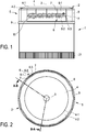
- the mixing and dosing 1 is formed in this example as already described. You can see them in the Fig. 1 only the container body 20, which forms a substantially cylindrical interior, and the actuator 21 of the engaging in the breakthrough of the piston unit drive unit, by its manual operation, here by turning, the piston unit towards a closed by the lid 2 outlet for dispensing Mixture can be moved.
- the Fig. 1 shows the state of the mixing and dosing after the mixing process in which the drive unit is already connected to the container body 20 and the piston unit serves as a movable means of the drive means dosing. During the mixing process, the drive unit with the actuator 21 is not yet used and the breakthrough of the piston unit serves as a guide for the drive shaft of the mixing tool.
- the inventors have now found that in typical mixing operations of pharmaceutical, cosmetic or similar products comparatively high demands on the fixation of the mixing and metering container during the mixing process exist.
- tilting of the mixing and metering container can lead to tilting of the mixing tool in the interior of the container body.
- This can lead to impairments in the mixing process at speeds of rotation of the mixing tool, which may be between 500 and 1500 revolutions per minute (rpm), depending on the product to be mixed or mixed, as well as being problematic for safety reasons.
- the lid 2 in this embodiment of the invention is designed as follows:
- the lid 2 has a central axis 3, a lid top 4 arranged at least approximately orthogonally to the central axis 3, and a lid edge 5 adjoining the lid upper side 4.
- the lid edge 5 has at least one clamping flank which contains a first section 6-1 which is closer to the top side 4 and a second section 6-2 further spaced from the lid top 4, which have at least one common edge 7 at least approximately parallel to the central axis 3.
- the distance of the clamping edge 6 to the central axis 3 in the first section 6-1 at least in an area smaller than the distance of the edge edge 7 to the central axis 3 and as the distance of the clamping edge 6 to the central axis 3 in a circumferential direction of the lid edge 5 corresponding area of second section 6-2. This will be explained below in greater detail with reference to the Figs. 2 to 6 be explained.
- each case four clamping flanks 6 are arranged side by side and the two groups of four adjacent clamping flanks 6 are arranged symmetrically to the central axis 3 on opposite sides of the lid edge 5.
- the Fig. 2 one recognizes the one group of four adjacent clamping flanks 6 in the lower part of the illustration, the other Group on the opposite side of the lid edge 5 in the upper part of the illustration.
- the Fig. 1 One of the two groups of Frontal can be seen in the middle of the lid 2. The other group is arranged on the opposite side of the lid edge 5 and therefore hidden in this representation.
- the clamping flank 6 has a first section 6-1 which is closer to the top side 4 of the cover and a second section 6-2 which is further spaced from the cover top 4 and which has at least one common flank edge 7 parallel to the central axis 3.
- the clamping flank 6 has the same distance to the central axis 3 at the edge edges 7 both in the first section 6-1 and in the second section 6-2, ie the flank edges 7 form straight lines in the circumferential surface of a cylinder around the Center axis 3 are.
- this commonality does not apply to the remaining part of the clamping edge 6.
- the lid edge 5 has further supporting flanks 8.
- the support flanks 8, of which eight are also provided in this embodiment, have substantially the shape of a plane parallel to the central axis 3, flat surface, ie, they are similar to the first portion 6-1 of the clamping flanks 6.
- the support flanks 8 therefore not in the measure a clamping function as the clamping edges 6, but they contribute to the support of the lid 2 in the fixing device 110 and counteract tilting of the mixing and dosing 1 during the mixing process.
- the supporting flanks 8 - as well as the clamping flanks 6 - arranged in two groups of four flanks symmetrical to the central axis 3 on opposite sides of the lid edge 5.
- the slope of the change in distance in the third section 6-3 is not more than 45 °, preferably not more than 35 °, more preferably not more than 25 °. This counteracts tilting of the mixing and dosing container 1 when the lid 2 is inserted into the fixing device.
- the third section 6-3 in this embodiment is approximately at the middle of the height of the clamping edge 6 and the height of the third section 6-3 is between 20% and 40% of the height of the clamping edge 6, preferably between 0.5 cm and 1.5 cm.
- the cover 2 may already be relatively stable aligned when it was inserted to the height of the first portion 6-1 in the fixing device 110, wherein the further insertion over the height of the first portion 6-1 addition, and thus with the second section 6-2 of the clamping edge 6, the desired clamping can be done with a low risk of subsequent tilting.
- the lid edge 5 is closed with a radially outwardly projecting, substantially circular end edge 9. This can additionally provide for the desired orientation of the mixing and dosing 1 with completely inserted into the fixing device 110 cover 2. As already described, a secure fixation during a mixing process can thus be made possible in a simple manner.
- the first section 6-1 which here has substantially the shape of a plane parallel to the central axis 3, flat surface
- the second section 6-2 which here essentially has the shape of a section of the lateral surface of the cylinder about the central axis 3
- the third section 6-3 within which the change of the distance of the clamping flanks 6 to the central axis 3 from the central axis. 3 parallel, flat surface in the first section 6-1 to the cutout of the lateral surface of the cylinder about the central axis 3 in the second section 6-2.
- both the clamping flanks 6 and the supporting flanks 8 also have a small chamfer in the region in which they adjoin the chamfer 4-2 of the top side 4 of the cover.
- the substantially circular end edge 9 of the lid 2 is connected to the support flanks 8 with a small chamfer.
- the first portion 6-1 of the clamping flanks 6 and the supporting flanks 8 appear to be concave. However, this is an optical illusion caused by the aforementioned chamfers.
- FIG. 3 shows the Fig. 3 schematically and exemplarily a sectional view of the lid 2 from the Fig. 1 along in the Fig. 2 shown lines AB and BA
- the Fig. 4 shows schematically and exemplarily an enlarged view of the in the Fig. 3 shown area AA of the lid 2 from the Fig. 1
- the distance between the clamping flank 6 and the central axis 3 is smaller as the distance of the clamping edge 6 to the central axis 3 in the shown portion of the second section 6-2.
- the cover 2 also has a cover inside 11, which has an inwardly projecting element 12 for sealingly sealing an outlet of the mixing and metering container 1.
- the cover 2 has an internal thread 13 for screwing the lid 2 onto the mixing and dosing container 1.
- a lid has been described for a mixing and dosing container for pharmaceutical, cosmetic or similar products, for temporary fixing in a fixing device, which has a cylindrical or annular recess with a plurality of inwardly projecting, flattened teeth, wherein the lid a Central axis, a top side arranged orthogonally to the central axis and having a lid edge adjoining the lid top, wherein the lid edge has at least one clamping edge, which includes a closer to the lid top first portion and a lid of the top further spaced second portion which at least one common, to Central axis at least approximately parallel flank edge, wherein the distance of the clamping edge to the central axis in the first section at least in an area is smaller than the distance of the edge edge to the central axis and as the Abstan d the clamping edge to the central axis in an area corresponding in the circumferential direction of the lid edge portion of the second portion.
Landscapes
- Chemical & Material Sciences (AREA)
- Chemical Kinetics & Catalysis (AREA)
- Engineering & Computer Science (AREA)
- Mechanical Engineering (AREA)
- Closures For Containers (AREA)
Priority Applications (1)
| Application Number | Priority Date | Filing Date | Title |
|---|---|---|---|
| SI201830123T SI3444200T1 (sl) | 2017-08-14 | 2018-08-10 | Pokrov za mešalni in dozirni vsebnik |
Applications Claiming Priority (1)
| Application Number | Priority Date | Filing Date | Title |
|---|---|---|---|
| DE202017104889.6U DE202017104889U1 (de) | 2017-08-14 | 2017-08-14 | Deckel für einen Misch- und Dosierbehälter |
Publications (2)
| Publication Number | Publication Date |
|---|---|
| EP3444200A1 true EP3444200A1 (fr) | 2019-02-20 |
| EP3444200B1 EP3444200B1 (fr) | 2020-09-16 |
Family
ID=59814771
Family Applications (1)
| Application Number | Title | Priority Date | Filing Date |
|---|---|---|---|
| EP18188510.4A Active EP3444200B1 (fr) | 2017-08-14 | 2018-08-10 | Couvercle pour un récipient de mélange et de dosage |
Country Status (3)
| Country | Link |
|---|---|
| EP (1) | EP3444200B1 (fr) |
| DE (1) | DE202017104889U1 (fr) |
| SI (1) | SI3444200T1 (fr) |
Citations (5)
| Publication number | Priority date | Publication date | Assignee | Title |
|---|---|---|---|---|
| EP0920907A2 (fr) | 1997-12-05 | 1999-06-09 | WEPA Paulus & Thewalt GmbH & Co. Apotheken-Bedarf | Conteneur de mélange et de dosage |
| EP2363201A1 (fr) * | 2010-03-04 | 2011-09-07 | WEPA Apothekenbedarf GmbH & Co.KG | Système de mélange de préparations individuelles pharmaceutiques et/ou cosmétiques, béquille et dispositif de fixation associés |
| EP2659958A1 (fr) | 2012-05-03 | 2013-11-06 | WEPA Apothekenbedarf GmbH & Co.KG | Élément de mélange denté |
| KR20160050806A (ko) * | 2014-10-31 | 2016-05-11 | 김용운 | 거치식 양념 수납 장치 |
| US20170021978A1 (en) * | 2015-07-20 | 2017-01-26 | Tennessee Bottle Co., Inc. | Back-off resistant closure system |
-
2017
- 2017-08-14 DE DE202017104889.6U patent/DE202017104889U1/de active Active
-
2018
- 2018-08-10 SI SI201830123T patent/SI3444200T1/sl unknown
- 2018-08-10 EP EP18188510.4A patent/EP3444200B1/fr active Active
Patent Citations (5)
| Publication number | Priority date | Publication date | Assignee | Title |
|---|---|---|---|---|
| EP0920907A2 (fr) | 1997-12-05 | 1999-06-09 | WEPA Paulus & Thewalt GmbH & Co. Apotheken-Bedarf | Conteneur de mélange et de dosage |
| EP2363201A1 (fr) * | 2010-03-04 | 2011-09-07 | WEPA Apothekenbedarf GmbH & Co.KG | Système de mélange de préparations individuelles pharmaceutiques et/ou cosmétiques, béquille et dispositif de fixation associés |
| EP2659958A1 (fr) | 2012-05-03 | 2013-11-06 | WEPA Apothekenbedarf GmbH & Co.KG | Élément de mélange denté |
| KR20160050806A (ko) * | 2014-10-31 | 2016-05-11 | 김용운 | 거치식 양념 수납 장치 |
| US20170021978A1 (en) * | 2015-07-20 | 2017-01-26 | Tennessee Bottle Co., Inc. | Back-off resistant closure system |
Also Published As
| Publication number | Publication date |
|---|---|
| EP3444200B1 (fr) | 2020-09-16 |
| DE202017104889U1 (de) | 2017-08-22 |
| SI3444200T1 (sl) | 2020-12-31 |
Similar Documents
| Publication | Publication Date | Title |
|---|---|---|
| DE60031219T2 (de) | Verschlusskappe für wiederholtes durchstechen | |
| EP2968796B1 (fr) | Embout pour une seringue ou carpule | |
| EP2616347B1 (fr) | Dispositif d'ouverture refermable pour emballage scellé | |
| DE69723198T2 (de) | Spritze mit einem luer-lock Teil | |
| AT398300B (de) | Zweiteiliger abgabeverschluss | |
| DE69835722T2 (de) | Behälter zur getrennten Aufbewahrung und Mischung von zwei Produkten, und Verfahren zur Herstellung dieses Behälters | |
| WO2004069066A1 (fr) | Dispositif orthopedique implantable | |
| DE102012022008A1 (de) | Spritzenverschluss | |
| DE102007007474B3 (de) | Behältnis | |
| DE2923379A1 (de) | Flaschenverschluss | |
| EP2885087A1 (fr) | Dispositif d'extraction | |
| EP1254842A1 (fr) | Recipient plastique | |
| EP3638357B1 (fr) | Seringue équipée d'un embout luer-lock | |
| DE102008049265A1 (de) | Mischer | |
| DE69025320T2 (de) | Flasche mit Tropfvorrichtung | |
| EP0600284A1 (fr) | Elément de fixation | |
| EP3444200B1 (fr) | Couvercle pour un récipient de mélange et de dosage | |
| EP1482231A1 (fr) | Raccord rapide | |
| EP2037833A1 (fr) | Dispositif de maintien et d'emballage pour un implant dentaire | |
| DE102013007063A1 (de) | Behältnis | |
| WO2007068011A1 (fr) | Dispositif de fermeture universelle | |
| EP2885088B1 (fr) | Dispositif de sortie | |
| DE2449516C3 (de) | Flaschenverschluß mit einem Ausgießkörper | |
| DE102011017797A1 (de) | Verschliessbare Öffnungsvorrichtung für eine versiegelte Verpackung | |
| DE1810299A1 (de) | Hilfsgeraet zur Herstellung steriler Loesungen |
Legal Events
| Date | Code | Title | Description |
|---|---|---|---|
| PUAI | Public reference made under article 153(3) epc to a published international application that has entered the european phase |
Free format text: ORIGINAL CODE: 0009012 |
|
| STAA | Information on the status of an ep patent application or granted ep patent |
Free format text: STATUS: THE APPLICATION HAS BEEN PUBLISHED |
|
| AK | Designated contracting states |
Kind code of ref document: A1 Designated state(s): AL AT BE BG CH CY CZ DE DK EE ES FI FR GB GR HR HU IE IS IT LI LT LU LV MC MK MT NL NO PL PT RO RS SE SI SK SM TR |
|
| AX | Request for extension of the european patent |
Extension state: BA ME |
|
| STAA | Information on the status of an ep patent application or granted ep patent |
Free format text: STATUS: REQUEST FOR EXAMINATION WAS MADE |
|
| 17P | Request for examination filed |
Effective date: 20190820 |
|
| RBV | Designated contracting states (corrected) |
Designated state(s): AL AT BE BG CH CY CZ DE DK EE ES FI FR GB GR HR HU IE IS IT LI LT LU LV MC MK MT NL NO PL PT RO RS SE SI SK SM TR |
|
| GRAP | Despatch of communication of intention to grant a patent |
Free format text: ORIGINAL CODE: EPIDOSNIGR1 |
|
| STAA | Information on the status of an ep patent application or granted ep patent |
Free format text: STATUS: GRANT OF PATENT IS INTENDED |
|
| RIC1 | Information provided on ipc code assigned before grant |
Ipc: B01F 15/00 20060101ALI20200221BHEP Ipc: B65D 51/24 20060101AFI20200221BHEP |
|
| INTG | Intention to grant announced |
Effective date: 20200323 |
|
| GRAS | Grant fee paid |
Free format text: ORIGINAL CODE: EPIDOSNIGR3 |
|
| GRAA | (expected) grant |
Free format text: ORIGINAL CODE: 0009210 |
|
| STAA | Information on the status of an ep patent application or granted ep patent |
Free format text: STATUS: THE PATENT HAS BEEN GRANTED |
|
| AK | Designated contracting states |
Kind code of ref document: B1 Designated state(s): AL AT BE BG CH CY CZ DE DK EE ES FI FR GB GR HR HU IE IS IT LI LT LU LV MC MK MT NL NO PL PT RO RS SE SI SK SM TR |
|
| REG | Reference to a national code |
Ref country code: GB Ref legal event code: FG4D Free format text: NOT ENGLISH |
|
| REG | Reference to a national code |
Ref country code: CH Ref legal event code: EP |
|
| REG | Reference to a national code |
Ref country code: DE Ref legal event code: R096 Ref document number: 502018002460 Country of ref document: DE |
|
| REG | Reference to a national code |
Ref country code: IE Ref legal event code: FG4D Free format text: LANGUAGE OF EP DOCUMENT: GERMAN |
|
| REG | Reference to a national code |
Ref country code: AT Ref legal event code: REF Ref document number: 1313989 Country of ref document: AT Kind code of ref document: T Effective date: 20201015 |
|
| REG | Reference to a national code |
Ref country code: CH Ref legal event code: NV Representative=s name: E. BLUM AND CO. AG PATENT- UND MARKENANWAELTE , CH |
|
| PG25 | Lapsed in a contracting state [announced via postgrant information from national office to epo] |
Ref country code: GR Free format text: LAPSE BECAUSE OF FAILURE TO SUBMIT A TRANSLATION OF THE DESCRIPTION OR TO PAY THE FEE WITHIN THE PRESCRIBED TIME-LIMIT Effective date: 20201217 Ref country code: NO Free format text: LAPSE BECAUSE OF FAILURE TO SUBMIT A TRANSLATION OF THE DESCRIPTION OR TO PAY THE FEE WITHIN THE PRESCRIBED TIME-LIMIT Effective date: 20201216 Ref country code: SE Free format text: LAPSE BECAUSE OF FAILURE TO SUBMIT A TRANSLATION OF THE DESCRIPTION OR TO PAY THE FEE WITHIN THE PRESCRIBED TIME-LIMIT Effective date: 20200916 Ref country code: FI Free format text: LAPSE BECAUSE OF FAILURE TO SUBMIT A TRANSLATION OF THE DESCRIPTION OR TO PAY THE FEE WITHIN THE PRESCRIBED TIME-LIMIT Effective date: 20200916 Ref country code: HR Free format text: LAPSE BECAUSE OF FAILURE TO SUBMIT A TRANSLATION OF THE DESCRIPTION OR TO PAY THE FEE WITHIN THE PRESCRIBED TIME-LIMIT Effective date: 20200916 Ref country code: BG Free format text: LAPSE BECAUSE OF FAILURE TO SUBMIT A TRANSLATION OF THE DESCRIPTION OR TO PAY THE FEE WITHIN THE PRESCRIBED TIME-LIMIT Effective date: 20201216 |
|
| REG | Reference to a national code |
Ref country code: NL Ref legal event code: MP Effective date: 20200916 |
|
| PG25 | Lapsed in a contracting state [announced via postgrant information from national office to epo] |
Ref country code: LV Free format text: LAPSE BECAUSE OF FAILURE TO SUBMIT A TRANSLATION OF THE DESCRIPTION OR TO PAY THE FEE WITHIN THE PRESCRIBED TIME-LIMIT Effective date: 20200916 Ref country code: RS Free format text: LAPSE BECAUSE OF FAILURE TO SUBMIT A TRANSLATION OF THE DESCRIPTION OR TO PAY THE FEE WITHIN THE PRESCRIBED TIME-LIMIT Effective date: 20200916 |
|
| REG | Reference to a national code |
Ref country code: LT Ref legal event code: MG4D |
|
| PG25 | Lapsed in a contracting state [announced via postgrant information from national office to epo] |
Ref country code: LT Free format text: LAPSE BECAUSE OF FAILURE TO SUBMIT A TRANSLATION OF THE DESCRIPTION OR TO PAY THE FEE WITHIN THE PRESCRIBED TIME-LIMIT Effective date: 20200916 Ref country code: SM Free format text: LAPSE BECAUSE OF FAILURE TO SUBMIT A TRANSLATION OF THE DESCRIPTION OR TO PAY THE FEE WITHIN THE PRESCRIBED TIME-LIMIT Effective date: 20200916 Ref country code: EE Free format text: LAPSE BECAUSE OF FAILURE TO SUBMIT A TRANSLATION OF THE DESCRIPTION OR TO PAY THE FEE WITHIN THE PRESCRIBED TIME-LIMIT Effective date: 20200916 Ref country code: CZ Free format text: LAPSE BECAUSE OF FAILURE TO SUBMIT A TRANSLATION OF THE DESCRIPTION OR TO PAY THE FEE WITHIN THE PRESCRIBED TIME-LIMIT Effective date: 20200916 Ref country code: PT Free format text: LAPSE BECAUSE OF FAILURE TO SUBMIT A TRANSLATION OF THE DESCRIPTION OR TO PAY THE FEE WITHIN THE PRESCRIBED TIME-LIMIT Effective date: 20210118 Ref country code: RO Free format text: LAPSE BECAUSE OF FAILURE TO SUBMIT A TRANSLATION OF THE DESCRIPTION OR TO PAY THE FEE WITHIN THE PRESCRIBED TIME-LIMIT Effective date: 20200916 |
|
| PG25 | Lapsed in a contracting state [announced via postgrant information from national office to epo] |
Ref country code: IS Free format text: LAPSE BECAUSE OF FAILURE TO SUBMIT A TRANSLATION OF THE DESCRIPTION OR TO PAY THE FEE WITHIN THE PRESCRIBED TIME-LIMIT Effective date: 20210116 Ref country code: PL Free format text: LAPSE BECAUSE OF FAILURE TO SUBMIT A TRANSLATION OF THE DESCRIPTION OR TO PAY THE FEE WITHIN THE PRESCRIBED TIME-LIMIT Effective date: 20200916 Ref country code: AL Free format text: LAPSE BECAUSE OF FAILURE TO SUBMIT A TRANSLATION OF THE DESCRIPTION OR TO PAY THE FEE WITHIN THE PRESCRIBED TIME-LIMIT Effective date: 20200916 Ref country code: ES Free format text: LAPSE BECAUSE OF FAILURE TO SUBMIT A TRANSLATION OF THE DESCRIPTION OR TO PAY THE FEE WITHIN THE PRESCRIBED TIME-LIMIT Effective date: 20200916 |
|
| REG | Reference to a national code |
Ref country code: DE Ref legal event code: R097 Ref document number: 502018002460 Country of ref document: DE |
|
| PG25 | Lapsed in a contracting state [announced via postgrant information from national office to epo] |
Ref country code: SK Free format text: LAPSE BECAUSE OF FAILURE TO SUBMIT A TRANSLATION OF THE DESCRIPTION OR TO PAY THE FEE WITHIN THE PRESCRIBED TIME-LIMIT Effective date: 20200916 |
|
| PLBE | No opposition filed within time limit |
Free format text: ORIGINAL CODE: 0009261 |
|
| STAA | Information on the status of an ep patent application or granted ep patent |
Free format text: STATUS: NO OPPOSITION FILED WITHIN TIME LIMIT |
|
| 26N | No opposition filed |
Effective date: 20210617 |
|
| PG25 | Lapsed in a contracting state [announced via postgrant information from national office to epo] |
Ref country code: DK Free format text: LAPSE BECAUSE OF FAILURE TO SUBMIT A TRANSLATION OF THE DESCRIPTION OR TO PAY THE FEE WITHIN THE PRESCRIBED TIME-LIMIT Effective date: 20200916 |
|
| PG25 | Lapsed in a contracting state [announced via postgrant information from national office to epo] |
Ref country code: MC Free format text: LAPSE BECAUSE OF FAILURE TO SUBMIT A TRANSLATION OF THE DESCRIPTION OR TO PAY THE FEE WITHIN THE PRESCRIBED TIME-LIMIT Effective date: 20200916 |
|
| PG25 | Lapsed in a contracting state [announced via postgrant information from national office to epo] |
Ref country code: IE Free format text: LAPSE BECAUSE OF NON-PAYMENT OF DUE FEES Effective date: 20210810 |
|
| GBPC | Gb: european patent ceased through non-payment of renewal fee |
Effective date: 20220810 |
|
| PG25 | Lapsed in a contracting state [announced via postgrant information from national office to epo] |
Ref country code: NL Free format text: LAPSE BECAUSE OF NON-PAYMENT OF DUE FEES Effective date: 20200923 Ref country code: CY Free format text: LAPSE BECAUSE OF FAILURE TO SUBMIT A TRANSLATION OF THE DESCRIPTION OR TO PAY THE FEE WITHIN THE PRESCRIBED TIME-LIMIT Effective date: 20200916 |
|
| PG25 | Lapsed in a contracting state [announced via postgrant information from national office to epo] |
Ref country code: HU Free format text: LAPSE BECAUSE OF FAILURE TO SUBMIT A TRANSLATION OF THE DESCRIPTION OR TO PAY THE FEE WITHIN THE PRESCRIBED TIME-LIMIT; INVALID AB INITIO Effective date: 20180810 |
|
| PG25 | Lapsed in a contracting state [announced via postgrant information from national office to epo] |
Ref country code: GB Free format text: LAPSE BECAUSE OF NON-PAYMENT OF DUE FEES Effective date: 20220810 |
|
| PG25 | Lapsed in a contracting state [announced via postgrant information from national office to epo] |
Ref country code: MK Free format text: LAPSE BECAUSE OF FAILURE TO SUBMIT A TRANSLATION OF THE DESCRIPTION OR TO PAY THE FEE WITHIN THE PRESCRIBED TIME-LIMIT Effective date: 20200916 |
|
| PG25 | Lapsed in a contracting state [announced via postgrant information from national office to epo] |
Ref country code: TR Free format text: LAPSE BECAUSE OF FAILURE TO SUBMIT A TRANSLATION OF THE DESCRIPTION OR TO PAY THE FEE WITHIN THE PRESCRIBED TIME-LIMIT Effective date: 20200916 |
|
| PG25 | Lapsed in a contracting state [announced via postgrant information from national office to epo] |
Ref country code: MT Free format text: LAPSE BECAUSE OF FAILURE TO SUBMIT A TRANSLATION OF THE DESCRIPTION OR TO PAY THE FEE WITHIN THE PRESCRIBED TIME-LIMIT Effective date: 20200916 |
|
| PGFP | Annual fee paid to national office [announced via postgrant information from national office to epo] |
Ref country code: LU Payment date: 20250820 Year of fee payment: 8 |
|
| PGFP | Annual fee paid to national office [announced via postgrant information from national office to epo] |
Ref country code: DE Payment date: 20250908 Year of fee payment: 8 |
|
| PGFP | Annual fee paid to national office [announced via postgrant information from national office to epo] |
Ref country code: IT Payment date: 20250829 Year of fee payment: 8 |
|
| PGFP | Annual fee paid to national office [announced via postgrant information from national office to epo] |
Ref country code: BE Payment date: 20250820 Year of fee payment: 8 |
|
| PGFP | Annual fee paid to national office [announced via postgrant information from national office to epo] |
Ref country code: FR Payment date: 20250821 Year of fee payment: 8 Ref country code: AT Payment date: 20250819 Year of fee payment: 8 |
|
| PGFP | Annual fee paid to national office [announced via postgrant information from national office to epo] |
Ref country code: CH Payment date: 20250901 Year of fee payment: 8 |
|
| PGFP | Annual fee paid to national office [announced via postgrant information from national office to epo] |
Ref country code: SI Payment date: 20250728 Year of fee payment: 8 |