EP2659958A1 - Élément de mélange denté - Google Patents
Élément de mélange denté Download PDFInfo
- Publication number
- EP2659958A1 EP2659958A1 EP20120003246 EP12003246A EP2659958A1 EP 2659958 A1 EP2659958 A1 EP 2659958A1 EP 20120003246 EP20120003246 EP 20120003246 EP 12003246 A EP12003246 A EP 12003246A EP 2659958 A1 EP2659958 A1 EP 2659958A1
- Authority
- EP
- European Patent Office
- Prior art keywords
- stirring
- mixing element
- spoke
- mixing
- element according
- Prior art date
- Legal status (The legal status is an assumption and is not a legal conclusion. Google has not performed a legal analysis and makes no representation as to the accuracy of the status listed.)
- Granted
Links
Images


Classifications
-
- B—PERFORMING OPERATIONS; TRANSPORTING
- B01—PHYSICAL OR CHEMICAL PROCESSES OR APPARATUS IN GENERAL
- B01F—MIXING, e.g. DISSOLVING, EMULSIFYING OR DISPERSING
- B01F27/00—Mixers with rotary stirring devices in fixed receptacles; Kneaders
- B01F27/05—Stirrers
- B01F27/07—Stirrers characterised by their mounting on the shaft
- B01F27/072—Stirrers characterised by their mounting on the shaft characterised by the disposition of the stirrers with respect to the rotating axis
- B01F27/0725—Stirrers characterised by their mounting on the shaft characterised by the disposition of the stirrers with respect to the rotating axis on the free end of the rotating axis
-
- B—PERFORMING OPERATIONS; TRANSPORTING
- B01—PHYSICAL OR CHEMICAL PROCESSES OR APPARATUS IN GENERAL
- B01F—MIXING, e.g. DISSOLVING, EMULSIFYING OR DISPERSING
- B01F27/00—Mixers with rotary stirring devices in fixed receptacles; Kneaders
- B01F27/05—Stirrers
- B01F27/11—Stirrers characterised by the configuration of the stirrers
- B01F27/113—Propeller-shaped stirrers for producing an axial flow, e.g. shaped like a ship or aircraft propeller
- B01F27/1131—Propeller-shaped stirrers for producing an axial flow, e.g. shaped like a ship or aircraft propeller with holes in the propeller blade surface
-
- B—PERFORMING OPERATIONS; TRANSPORTING
- B01—PHYSICAL OR CHEMICAL PROCESSES OR APPARATUS IN GENERAL
- B01F—MIXING, e.g. DISSOLVING, EMULSIFYING OR DISPERSING
- B01F27/00—Mixers with rotary stirring devices in fixed receptacles; Kneaders
- B01F27/05—Stirrers
- B01F27/11—Stirrers characterised by the configuration of the stirrers
- B01F27/113—Propeller-shaped stirrers for producing an axial flow, e.g. shaped like a ship or aircraft propeller
- B01F27/1132—Propeller-shaped stirrers for producing an axial flow, e.g. shaped like a ship or aircraft propeller with guiding tubes or tubular segments fixed to and surrounding the tips of the propeller blades, e.g. for supplementary mixing
-
- B—PERFORMING OPERATIONS; TRANSPORTING
- B01—PHYSICAL OR CHEMICAL PROCESSES OR APPARATUS IN GENERAL
- B01F—MIXING, e.g. DISSOLVING, EMULSIFYING OR DISPERSING
- B01F31/00—Mixers with shaking, oscillating, or vibrating mechanisms
- B01F31/40—Mixers with shaking, oscillating, or vibrating mechanisms with an axially oscillating rotary stirrer
Definitions
- the invention relates to a mixing element for mixing medical, pharmaceutical or cosmetic products according to the preamble of claim 1.
- a mixing element for mixing medical, pharmaceutical or cosmetic products which is a hub for preferably reversible rotationally and axially fixed coupling comprising a drive shaft of a stirrer, an at least approximately concentrically arranged around the hub, annular Rownteilin, and at least one spoke element for rotationally and axially fixed connecting the Rntonteilanys with the hub.
- a mixing element can be, for example, a mixing disk in which an annular stirring part is arranged concentrically around a hub provided centrally for this purpose.
- the stirring member and the hub are firmly connected to each other by a plurality of webs extending radially from the hub.
- the hub is in turn coupled by a rotationally and axially fixed coupling with the end of a drive shaft of a stirrer.
- This coupling is either a permanent or a detachable connection.
- the drive shaft is rotated by the drive of the mixer in rotation, whereby the mixing disk is brought into a rotational movement.
- the mixing disk is positioned in the mixing or stirring vessel. After the individual mixture components have also been introduced into the mixing vessel, the mixing disk is rotated by the drive shaft. Due to the rotational or rotational movement and any additional stroke movement of the mixing disk, the individual mixture components are mixed together to produce the final product.
- a mixing disk is for example in the EP patent 0 987 055 disclosed.
- the mixture constituents to be mixed together for the production of medical, pharmaceutical or cosmetic products are often constituents of different consistency.
- the mixture components often have a different density and / or a different viscosity.
- some of the mixture components may also contain suspended particles in the form of small solids, which may occur in different amounts and sizes in the respective components. It is also possible that mixture components should be mixed in powder form with liquid mixture components. Because of these different physical properties and the different states of aggregation of the individual constituents of the mixture, there is often no uniform mixing behavior when mixing these constituents to form a final product.
- the individual constituents and any suspended particles which may be present move with one high density or high viscosity in the mixing process rather in the outer edge region of the mixing or mixing vessel, ie away from the inner region between the stirring and drive shaft.
- the mixing components and possibly existing suspended particles with a low density or a low viscosity during the mixing process tend to move into the inner region between the stirring part and the hub. Due to this different behavior and the different positioning of the individual mixture constituents to one another, the mixing process for achieving a homogeneously mixed end product can be substantially prolonged or not terminated at all.
- a mixing element for mixing medical, pharmaceutical or cosmetic products that a hub for preferably reversible rotationally and axially fixed coupling with a drive shaft of a stirrer, at least approximately concentrically arranged around the hub, annular Rownteilin and at least one spokes element for rotating and axially fixed connecting the Rownteilins with the hub. It is further provided that at least two stirring teeth are provided on the outer peripheral side of the Rntonteilins, and that the mean circumferential length of at least one stirring tooth, as viewed in the plane of the Rckenteilmois spanned central plane of the Rckenteilwheres, equal to the distance between two successive Rstoffzähen each other in the circumferential direction of the Rckenteilwheres is.
- the shape of at least one stirring tooth is considered in the plane of the Rownteilins spanned by the annular shape of the Rmaketeilins, at least approximately that of a trapezoid, preferably an isosceles trapezoid.
- the two parallel sides of the trapezoid extend in a circular arc corresponding to the ring shape of the Rownteilins.
- a stirring tooth may be that the shape of at least one stirring tooth, as viewed in the center plane of the stirring member carrier spanned by the annular shape of the stirring member carrier, is at least approximately that of a circular arc segment.
- the flanks facing in the two circumferential directions of the stirring member carrier have the same configuration.
- the ability to smash suspended particles, which are located in one or all of the mixture components of the mix can also be provided in an advantageous manner that at least one of the pointing in one of the circumferential directions of the Rixteilins flanks at least one stirring tooth extends at least approximately radially to the hub.
- this flank extends at least approximately perpendicular to one of the circumferential directions of the stirring member carrier or one of the directions of rotation of the mixing element.
- the stirring tooth provided with such an edge has the shape of a trapezoid
- this stirring tooth takes the form of a rectangular trapezium.
- the mixing element can be used so that upon rotation of the mixing element in a direction of rotation or in one of the circumferential directions of the Rownteilins in which the flank oblique (trapezoidal) or rounded (circular arc segmental shape), good mixing is achieved, whereas during a rotation of the mixing element in the opposite direction of rotation or circumferential direction of the Rhackteilins by the at least approximately radially extending flank a shattering of the suspended particles is achieved. Consequently, one and the same mixing element can be used for different tasks.
- stirring teeth can be provided on them in such a way that all the stirring teeth are the same or all the stirring teeth are unequal or the stirring teeth are arranged unequal and equal to one another.
- every second stirring tooth, the trapezoidal shape and each first stirring tooth, the circular arc segment shape, optionally with or without perpendicular flank can also be provided here regularly or irregularly.
- the outer surfaces of at least the stirring member carrier and the stirring teeth pointing in the direction of the central longitudinal axis or the rotational axis of the hub are arranged in two planes extending at least approximately parallel to each other and at least approximately perpendicular to the central longitudinal or rotational axis of the hub.
- the distance of the two planes smaller, preferably much smaller than the diameter of the Rhackteilins be selected.
- the diameter of the mixing element according to the invention can be selected to include the stirring teeth in accordance with the inner diameter of the stirring or mixing vessel. It is likewise possible for the diameter of the mixing element according to the invention, including the stirring teeth, to be smaller than the inner diameter of the stirring vessel. This makes it possible that the mixing element can be moved back and forth not only in the vertical direction in the mixing vessel, but that the mixing element can also perform a slight oscillating movement in a plane perpendicular to the central longitudinal or rotational axis of the hub. This also supports the mixing result, in particular the detachment of adhering to the inner peripheral wall of the mixing vessel components of the mix.
- a shape for a spoke element can advantageously consist in that the at least one spoke element has a first in the first circumferential direction of the Rownteilins or in the first direction of rotation of the mixing element facing the stirring surface and a second in the second circumferential direction of the Rmaketeilanis or in the second direction of rotation Mixing element facing stirring surface, wherein the two stirring surfaces of the spoke element at least approximately parallel to each other. It is also possible for the at least one spoke element to have a first stirring surface pointing in the first circumferential direction of the stirring member carrier or the first rotational direction and a second stirring face pointing in the second circumferential direction of the stirring member carrier or in the second rotational direction of the mixing element, wherein the first stirring surface and the second stirring surface are in two intersecting planes.
- At least one stirring surface of the at least one spoke element extends at least approximately perpendicular to one of the two circumferential directions of the stirring member carrier.
- At least one stirring surface of the at least one spoke element extends in a plane which is aligned obliquely to the circumferential direction of the Rhackteilyess or the direction of rotation of the mixing element.
- Such an oblique configuration allows easy penetration of the mixed material in the stirring process, whereby at the same time by the inclination of the stirring surface partial flows are generated in a direction parallel to the central longitudinal or rotational axis of the scar.
- spoke elements between the hub and Rhackteila be provided.
- the spoke elements may all have the same shape or different shapes, which also has the possibility that a first spoke element has a shape and the subsequent spoke element of a plurality of spoke elements another shape, this sequence then continues for all spoke elements.
- the at least one spoke element runs at least partially in a circular arc segment from the hub to the inner peripheral surface of the stirring member carrier in the center plane of the stirring member carrier spanned by the annular shape of the stirring member carrier.
- the at least one spoke element can also be configured radially or in a combination of radial and circular arc-shaped course.
- a plurality of spoke elements can be provided on a mixing element. These can, as well as the stirring teeth all be the same or regular or random alternately designed. Likewise, the orientation of the stirring surfaces of all spoke elements may be the same or different or may be provided on a spoke element two differently configured stirring surfaces. If the spoke elements have oblique stirring surfaces, it may further be provided that these stirring surfaces are aligned differently on successive spoke elements, i. in other words, that has an oblique stirring surface, for example in the direction of the bottom of the mixing vessel, whereas the other inclined stirring surface is aligned in the direction of the lid of the mixing vessel.
- spoke element can be used not only together with the above-described Rhackteilani and the stirring teeth but also independently thereof.
- the embodiments of the spoke element (s) can also be used in a mixing element which has no stirring member carrier and / or stirring teeth of the type explained above.
- the mixing element which consists of the hub, the at least one spoke element, the Rckenteilin and the at least two stirring teeth, integrally formed.
- material for the mixing element different materials can be used, it being advantageous that a suitable plastic is selected.
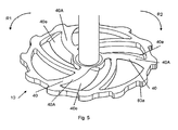
- Fig. 1 shows a perspective view of a first embodiment of the mixing element 10 according to the invention, which is coupled to an only partially shown drive shaft 20 of a known stirring device (not shown), which is used in the manufacture of medical, pharmaceutical or cosmetic products.
- the mixing element 10 according to the invention is often located in a suitable cylindrical mixing vessel, which is also referred to as a jug K.
- the mixing element 10 has as main components a hub 30, spoke elements 40 and an annular stirring member carrier 60 with stirring teeth 80. These components will be described in detail below.
- the mixing element 10 has a substantially flat upper side 12 and a substantially flat lower side (not shown), which extend at least approximately parallel. How out Fig. 1 it can be seen, the distance between the top 12 and the bottom is chosen so that the thickness of the mixing element 10 is much smaller than the diameter thereof.
- a substantially circular cylindrical cross-section having hub 30 includes an opening, not shown, for receiving the one end face of the drive shaft 20.
- This front end of the drive shaft 20 is in this case detachably coupled to the hub 30.
- the releasable coupling between drive shaft 20 and hub 30 may be provided by a connecting means, such as e.g. a bayonet lock or the like, be realized.
- a connecting means such as e.g. a bayonet lock or the like
- the mixing element 10 and the drive shaft 20 can be made together with the hub 30 in one piece.
- the other front end of the drive shaft 20, not shown, is connected to the drive of the mixer, also not shown.
- the mixing element 10 is in such an alignment with the drive shaft 20 that the top side 12 of the mixing element 10 to the mixer and the bottom in the direction of the bottom of a mixing or mixing vessel, also not shown.
- the mixing element 10 with the drive shaft 20 is releasably coupled or the mixing element 10 and the drive shaft 20, which can then form a one-piece unit, are releasably coupled to the drive means of the stirrer.
- a ready for sale unit consisting of a mixing vessel and a mixing element
- the drive shaft 20 possibly through a lid of the mixing vessel through and into the mixing vessel is introduced into and there is releasably coupled with the mixing element in a suitable manner.
- the drive shaft can then be separated again from the mixing element, wherein the mixing element remains in the mixing vessel.
- This solution is particularly advantageous if the mix can be contaminated by the ingress of ambient air.
- the mixing element 10 has a total of six spoke elements 40.
- two different configurations for the spoke elements 40 are provided, wherein the first group, consisting of three spoke elements 40 with the reference numeral 40A and the second group, also consisting of three spoke elements 40 is designated by the reference numeral 40B.
- the two groups 40A, 40B of the spoke elements 40 are alternately arranged in one of the two circumferential directions R1, R2 of the mixing element 10, ie, each spoke element 40 of the first group 40A is followed by a spoke element 40 of the second group 40B.
- the spoke elements 40 each include a first end 40a and a second end 40b. With the first end 40 a, the spoke members 40 are integrally connected to the outer peripheral side of the hub 30 and also connected to the second end 40 b integrally with the inner peripheral side of the stirring member carrier 60.
- the spoke elements 40 are in the of the ring shape of the Rhackteilins 60 spanned center plane arcuately curved like a circle, the curvatures of all spoke elements 40 are aligned the same.
- the spoke elements 40 Relative to the circumferential direction R1 of the mixing element 10, the spoke elements 40 have a convex / concave curvature.
- the radius of curvature is the same at least within each group 40A, 40B of spoke elements 40. However, it may vary between groups 40A, 40B.
- the two different groups 40A, 40B of spoke elements 40A, 40B differ in their cross-sectional shape.
- the two spoke flanks 40c, 40d which are in the two circumferential directions R1, R2 of the mixing element 10 and which are stirring surfaces are formed differently so as to extend in two intersecting "planes".
- the spoke flank 40c, which faces in the circumferential direction R1, which corresponds to the main direction of rotation of the mixing element 10 extends obliquely in the spoke element 40 of the first group 40A from the top 12 to the bottom (not shown) of the mixing element 10.
- the spoke flank 40d of the spoke member 40 of the first group 40A oriented in the circumferential direction R2 is oriented substantially perpendicular to the top 12 and bottom of the mixing element 10, that is, this spoke flank 40d is substantially perpendicular to the circumferential directions R1, R2. If the mixing element 10 is set in rotation in the circumferential direction R2, the spoke flank 40d can be used, for example, for shattering suspended particles possibly contained in a mixture constituent.
- the cross-sectional shape of the spoke elements 40 of the second group 40B is rectangular or square.
- the two stirring surfaces forming spoke flanks 40c, 40d are substantially parallel to one another.
- the cross-sectional area of the spoke member 40 of the second group 40B may be continuously changed from the outer peripheral surface of the hub 30 to the one Extend the inner peripheral surface of the Rhackteilyess 60.
- the width of the spoke elements 40 of the second group 40B, measured in one of the two circumferential directions R1, R2, is smaller than that of the first group 40A.
- the stirring member carrier 60 essentially consists of a ring element 62 with a rectangular or square cross section.
- the Rhackteillism 60 is rotatably and axially fixed by the spoke elements 40 to the hub 30.
- the stirring teeth of the embodiment according to Fig. 1 an arcuate segment-like shape, wherein in the direction of the circumferential direction R1 facing edge 80a of a stirring tooth 80 is cut off, ie this Rhak leopardflanke 80a extends radially to the ring member 62.
- the radial edge 80a allows easy detachment of adhering to the inner peripheral wall of the mixing vessel components of the mix.
- FIG. 3 to 7 Further embodiments of the mixing element 10 according to the invention are shown. These are similar to the mixing element 10 according to the Fig. 1 or designed so that only the differences are discussed below.
- the knife-like edge 40e of the first group 40A of the spoke elements 40 is convexly curved.
- the Rhackiereflanken 80a not in the circumferential direction R1 but in the circumferential direction R2.
- the mixing element 10 according to the Fig. 4 corresponds essentially to the mixing element 10 according to the Fig. 1 however, one difference is that the ends of the spoke members 40 of the second group 40B facing towards the hub 30 are not attached to the hub 30 but are integrally connected near the hub 30 to the spoke flank 40c of the spoke members 40 of the first group 40A ,
- mixing element 10 substantially corresponds to the mixing element 10 according to the Fig. 4 however, there is a difference that the blade-like edge 40e of the first group 40A of the spoke members 40 is convexly curved.
- the Rmmauerflanken 80a not in the circumferential direction R1 but in the circumferential direction R2.
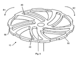
- the mixing element 10 of Fig. 6 corresponds essentially to the mixing element 10 of Fig. 4 , In contrast to the mixing element 10 of Fig. 4 However, the mixing element 10 is the Fig. 6 made filigree, ie the Speichenlemente 40 and the ring shape of the Rixteilins 60 are thinner or finer articulated. Another difference of the mixing element 10 of Fig. 6 is that the Stirring teeth 80 are designed in the form of a trapezoid, viewed in the plane spanned by the annular shape of the mixing element 10 level.
- Fig. 7 shows a mixing element 10, which substantially the mixing element 10 of Fig. 6 equivalent.
- a difference, however, is that the knife-like edge 40e of the first group 40A of the spoke elements 40 convexly curved.
- the mixing element 10 in addition to the rotational or rotational movement also undergoes a stroke movement.
- the drive shaft 20, at one end face of which the mixing element 10 is coupled in a rotationally and axially fixed manner is reciprocated at different intervals in a direction parallel to the axis of rotation D of the hub 30.
- the lifting movements are in this case set so that the mixing element 10 in a well-defined area within the in Fig. 2 shown stirring or mixing vessel (Kruke K) is moved up and down.
Landscapes
- Chemical & Material Sciences (AREA)
- Chemical Kinetics & Catalysis (AREA)
- Engineering & Computer Science (AREA)
- Aviation & Aerospace Engineering (AREA)
- Mixers Of The Rotary Stirring Type (AREA)
Priority Applications (1)
| Application Number | Priority Date | Filing Date | Title |
|---|---|---|---|
| EP12003246.1A EP2659958B1 (fr) | 2012-05-03 | 2012-05-03 | Élément de mélange denté |
Applications Claiming Priority (1)
| Application Number | Priority Date | Filing Date | Title |
|---|---|---|---|
| EP12003246.1A EP2659958B1 (fr) | 2012-05-03 | 2012-05-03 | Élément de mélange denté |
Publications (2)
| Publication Number | Publication Date |
|---|---|
| EP2659958A1 true EP2659958A1 (fr) | 2013-11-06 |
| EP2659958B1 EP2659958B1 (fr) | 2015-01-21 |
Family
ID=46178381
Family Applications (1)
| Application Number | Title | Priority Date | Filing Date |
|---|---|---|---|
| EP12003246.1A Active EP2659958B1 (fr) | 2012-05-03 | 2012-05-03 | Élément de mélange denté |
Country Status (1)
| Country | Link |
|---|---|
| EP (1) | EP2659958B1 (fr) |
Cited By (19)
| Publication number | Priority date | Publication date | Assignee | Title |
|---|---|---|---|---|
| DE102014221239B3 (de) * | 2014-10-20 | 2015-11-05 | Sms Elap Gmbh & Co. Kg | Rührwerkzeug und Rührgerät mit einem derartigen Werkzeug |
| DE202017104889U1 (de) | 2017-08-14 | 2017-08-22 | Wepa Apothekenbedarf Gmbh & Co.Kg | Deckel für einen Misch- und Dosierbehälter |
| CN110479132A (zh) * | 2019-05-05 | 2019-11-22 | 天津科技大学 | 一种蚊香盘状一体式搅拌部件及其制造方法 |
| CN111188922A (zh) * | 2018-11-14 | 2020-05-22 | 中核苏阀科技实业股份有限公司 | 带介质混合作用的阀体组件以及具有该阀体组件的闸阀 |
| USD891634S1 (en) | 2018-09-04 | 2020-07-28 | Reflex Medical Corp. | Agitator for pharmaceutical compounding |
| WO2021207080A1 (fr) * | 2020-04-06 | 2021-10-14 | Prc-Desoto International, Inc. | Impulseur mélangeur pour cartouches de produit d'étanchéité |
| US20220225635A1 (en) * | 2020-12-31 | 2022-07-21 | Sharkninja Operating Llc | Micro puree machine |
| US11503959B2 (en) | 2020-12-31 | 2022-11-22 | Sharkninja Operating Llc | Micro puree machine |
| US11540669B2 (en) | 2020-12-31 | 2023-01-03 | Sharkninja Operating Llc | Micro puree machine |
| WO2023048623A1 (fr) * | 2021-09-23 | 2023-03-30 | Lument Ab | Mélangeur d'agent de contraste |
| USD983603S1 (en) | 2020-12-31 | 2023-04-18 | Sharkninja Operating Llc | Blade for a micro puree machine |
| USD985334S1 (en) | 2020-12-31 | 2023-05-09 | Sharkninja Operating Llc | Nested bowl for a micro puree machine |
| USD985331S1 (en) | 2020-12-31 | 2023-05-09 | Sharkninja Operating Llc | Housing for a micro puree machine |
| US11672382B2 (en) | 2020-12-31 | 2023-06-13 | Sharkninja Operating Llc | Micro puree machine |
| US11864690B2 (en) | 2020-12-31 | 2024-01-09 | Sharkninja Operating Llc | Micro puree machine |
| WO2024058699A1 (fr) * | 2022-09-15 | 2024-03-21 | Lument Ab | Procédé de préparation d'un agent de contraste de type mousse homogène |
| US12016496B2 (en) | 2020-12-31 | 2024-06-25 | Sharkninja Operating Llc | Micro puree machine |
| US12022979B2 (en) | 2020-12-31 | 2024-07-02 | Sharkninja Operating Llc | Micro puree machine |
| US12575698B2 (en) | 2021-07-12 | 2026-03-17 | Sharkninja Operating Llc | Micro puree machine with selectable food processing routines and automated motor control |
Citations (9)
| Publication number | Priority date | Publication date | Assignee | Title |
|---|---|---|---|---|
| DE1026677B (de) * | 1956-03-12 | 1958-03-20 | Erich Geil Dipl Ing | Vorrichtung zur Herstellung von breiartigen, poroesen Massen, insbesondere von Luftporenbeton |
| DE1795244U (de) * | 1959-06-20 | 1959-09-10 | Henschel Werke G M B H | Ruehrwerkzeug. |
| DE1211905B (de) * | 1964-02-26 | 1966-03-03 | Draiswerke Ges Mit Beschraenkt | Ruehrwerksmuehle zum Herstellen von Feststoffdispersionen |
| DE2204558A1 (de) * | 1971-03-03 | 1972-09-14 | Allied Chem | Verfahren und Vorrichtung zur Herstellung von Polyesterpolymeren hoher Viskosität |
| US4813787A (en) * | 1987-07-23 | 1989-03-21 | Conn Leroy C | Blending apparatus |
| EP0896834A2 (fr) * | 1997-08-13 | 1999-02-17 | Wilhelm Niemann GmbH & Co., KG. | Dispositif de dispersion pour le mouillage complet de materiau pulvérulent sous forme de particules primaires |
| EP0987055A1 (fr) | 1998-09-15 | 2000-03-22 | WEPA Paulus & Thewalt GmbH & Co. Apotheken-Bedarf | Mélangeur |
| DE102007021056A1 (de) * | 2007-05-04 | 2008-11-06 | EKATO Rühr- und Mischtechnik GmbH | Rührorgan |
| DE19735539B4 (de) | 1997-08-16 | 2010-01-07 | Albrecht Konietzko | Vorrichtung zum Herstellen von Mischungen in einem Rührgeäß |
-
2012
- 2012-05-03 EP EP12003246.1A patent/EP2659958B1/fr active Active
Patent Citations (9)
| Publication number | Priority date | Publication date | Assignee | Title |
|---|---|---|---|---|
| DE1026677B (de) * | 1956-03-12 | 1958-03-20 | Erich Geil Dipl Ing | Vorrichtung zur Herstellung von breiartigen, poroesen Massen, insbesondere von Luftporenbeton |
| DE1795244U (de) * | 1959-06-20 | 1959-09-10 | Henschel Werke G M B H | Ruehrwerkzeug. |
| DE1211905B (de) * | 1964-02-26 | 1966-03-03 | Draiswerke Ges Mit Beschraenkt | Ruehrwerksmuehle zum Herstellen von Feststoffdispersionen |
| DE2204558A1 (de) * | 1971-03-03 | 1972-09-14 | Allied Chem | Verfahren und Vorrichtung zur Herstellung von Polyesterpolymeren hoher Viskosität |
| US4813787A (en) * | 1987-07-23 | 1989-03-21 | Conn Leroy C | Blending apparatus |
| EP0896834A2 (fr) * | 1997-08-13 | 1999-02-17 | Wilhelm Niemann GmbH & Co., KG. | Dispositif de dispersion pour le mouillage complet de materiau pulvérulent sous forme de particules primaires |
| DE19735539B4 (de) | 1997-08-16 | 2010-01-07 | Albrecht Konietzko | Vorrichtung zum Herstellen von Mischungen in einem Rührgeäß |
| EP0987055A1 (fr) | 1998-09-15 | 2000-03-22 | WEPA Paulus & Thewalt GmbH & Co. Apotheken-Bedarf | Mélangeur |
| DE102007021056A1 (de) * | 2007-05-04 | 2008-11-06 | EKATO Rühr- und Mischtechnik GmbH | Rührorgan |
Cited By (34)
| Publication number | Priority date | Publication date | Assignee | Title |
|---|---|---|---|---|
| WO2016062498A1 (fr) | 2014-10-20 | 2016-04-28 | Sms Elap Gmbh & Co. Kg | Outil d'agitation et appareil d'agitation muni d'un tel outil |
| US10493413B2 (en) | 2014-10-20 | 2019-12-03 | Samix Gmbh | Stirring tool and stirrer comprising a tool of said type |
| DE102014221239B3 (de) * | 2014-10-20 | 2015-11-05 | Sms Elap Gmbh & Co. Kg | Rührwerkzeug und Rührgerät mit einem derartigen Werkzeug |
| DE202017104889U1 (de) | 2017-08-14 | 2017-08-22 | Wepa Apothekenbedarf Gmbh & Co.Kg | Deckel für einen Misch- und Dosierbehälter |
| EP3444200A1 (fr) | 2017-08-14 | 2019-02-20 | WEPA Apothekenbedarf GmbH & Co.KG | Couvercle pour un récipient de mélange et de dosage |
| USD891634S1 (en) | 2018-09-04 | 2020-07-28 | Reflex Medical Corp. | Agitator for pharmaceutical compounding |
| CN111188922A (zh) * | 2018-11-14 | 2020-05-22 | 中核苏阀科技实业股份有限公司 | 带介质混合作用的阀体组件以及具有该阀体组件的闸阀 |
| CN110479132B (zh) * | 2019-05-05 | 2024-02-20 | 天津科技大学 | 一种蚊香盘状一体式搅拌部件及其制造方法 |
| CN110479132A (zh) * | 2019-05-05 | 2019-11-22 | 天津科技大学 | 一种蚊香盘状一体式搅拌部件及其制造方法 |
| WO2021207080A1 (fr) * | 2020-04-06 | 2021-10-14 | Prc-Desoto International, Inc. | Impulseur mélangeur pour cartouches de produit d'étanchéité |
| CN115666773A (zh) * | 2020-04-06 | 2023-01-31 | Prc-迪索托国际公司 | 用于密封剂料筒的混合叶轮 |
| KR20220163451A (ko) * | 2020-04-06 | 2022-12-09 | 피알시-데소토 인터내쇼날, 인코포레이티드 | 밀봉제 카트리지를 위한 혼합용 임펠러 |
| EP4132697A1 (fr) * | 2020-04-06 | 2023-02-15 | PRC-Desoto International, Inc. | Impulseur mélangeur pour cartouches de produit d'étanchéité |
| US11864690B2 (en) | 2020-12-31 | 2024-01-09 | Sharkninja Operating Llc | Micro puree machine |
| US20220225635A1 (en) * | 2020-12-31 | 2022-07-21 | Sharkninja Operating Llc | Micro puree machine |
| US12527334B2 (en) | 2020-12-31 | 2026-01-20 | Sharkninja Operating Llc | Micro puree machine |
| US11617378B2 (en) * | 2020-12-31 | 2023-04-04 | Sharkninja Operating Llc | Micro puree machine |
| USD983603S1 (en) | 2020-12-31 | 2023-04-18 | Sharkninja Operating Llc | Blade for a micro puree machine |
| USD985334S1 (en) | 2020-12-31 | 2023-05-09 | Sharkninja Operating Llc | Nested bowl for a micro puree machine |
| USD985331S1 (en) | 2020-12-31 | 2023-05-09 | Sharkninja Operating Llc | Housing for a micro puree machine |
| US11672382B2 (en) | 2020-12-31 | 2023-06-13 | Sharkninja Operating Llc | Micro puree machine |
| US11832767B2 (en) | 2020-12-31 | 2023-12-05 | Sharkninja Operating Llc | Micro puree machine |
| US11503959B2 (en) | 2020-12-31 | 2022-11-22 | Sharkninja Operating Llc | Micro puree machine |
| US11871765B2 (en) | 2020-12-31 | 2024-01-16 | Sharkninja Operating Llc | Micro puree machine |
| US11540669B2 (en) | 2020-12-31 | 2023-01-03 | Sharkninja Operating Llc | Micro puree machine |
| US11925298B2 (en) | 2020-12-31 | 2024-03-12 | Sharkninja Operating Llc | Micro puree machine |
| USD1041252S1 (en) | 2020-12-31 | 2024-09-10 | Sharkninja Operating Llc | Bowl for a micro puree machine |
| US12016493B2 (en) | 2020-12-31 | 2024-06-25 | Sharkninja Operating Llc | Micro puree machine |
| US12016496B2 (en) | 2020-12-31 | 2024-06-25 | Sharkninja Operating Llc | Micro puree machine |
| US12022979B2 (en) | 2020-12-31 | 2024-07-02 | Sharkninja Operating Llc | Micro puree machine |
| US12064056B2 (en) | 2020-12-31 | 2024-08-20 | Sharkninja (Hong Kong) Company Limited | Micro puree machine |
| US12575698B2 (en) | 2021-07-12 | 2026-03-17 | Sharkninja Operating Llc | Micro puree machine with selectable food processing routines and automated motor control |
| WO2023048623A1 (fr) * | 2021-09-23 | 2023-03-30 | Lument Ab | Mélangeur d'agent de contraste |
| WO2024058699A1 (fr) * | 2022-09-15 | 2024-03-21 | Lument Ab | Procédé de préparation d'un agent de contraste de type mousse homogène |
Also Published As
| Publication number | Publication date |
|---|---|
| EP2659958B1 (fr) | 2015-01-21 |
Similar Documents
| Publication | Publication Date | Title |
|---|---|---|
| EP2659958B1 (fr) | Élément de mélange denté | |
| EP2680958B1 (fr) | Mélangeur dynamique | |
| EP1278594B1 (fr) | Malaxeur a melange force a deux arbres, son utilisation et procede pour faire fonctionner un malaxeur a melange force a deux arbres | |
| DE68902085T2 (de) | Vierfluegelige rotoren fuer innenmischer. | |
| DE602005000098T2 (de) | Dynamische Durchfluss-Mischvorrichtung | |
| DE102004034371B3 (de) | Mischvorrichtung | |
| EP1216747A1 (fr) | Mélangeur statique | |
| DE60315052T2 (de) | Knetverfahren und Knetmaschine für Teigmittel, insbesondere für Backwaren | |
| DE102008016862A1 (de) | Extruder | |
| DE3344531A1 (de) | Mischvorrichtung | |
| EP2527029A2 (fr) | Mélangeur statique | |
| DE102015106419A1 (de) | Rührwerk und Behälter mit Rührwerk | |
| DE2627600C2 (de) | Vorrichtung zum diskontinuierlichen Mischen von mindestens zwei Stoffen | |
| DE1779259A1 (de) | Rotor fuer eine Maschine zum Mischen von Gummi,Kunststoff od.dgl. | |
| DE202006007423U1 (de) | Rührorgan | |
| DE1557230C3 (de) | Rührteil für einen Magnetrührer | |
| DE2643560C2 (de) | Rührvorrichtung | |
| DE2439683C2 (fr) | ||
| EP1155734A1 (fr) | Malaxeur vertical | |
| DE4334121A1 (de) | Maschine zum Kneten von Teig | |
| DE602004011873T2 (de) | Horizontale Knetmaschine für essbaren Teig, insbesondere für im Ofen gebackene Produkten | |
| DE2513577C3 (de) | Kontinuierlich arbeitender Mischer für plastische Massen | |
| DE1657370C3 (de) | Mischer mit einem liegenden Misch trog und auf einer Welle befestigten pilzförmigen Mischflugeln | |
| EP2052772A1 (fr) | Dissolveur | |
| DE2830029A1 (de) | Selbstreinigender mischer |
Legal Events
| Date | Code | Title | Description |
|---|---|---|---|
| PUAI | Public reference made under article 153(3) epc to a published international application that has entered the european phase |
Free format text: ORIGINAL CODE: 0009012 |
|
| AK | Designated contracting states |
Kind code of ref document: A1 Designated state(s): AL AT BE BG CH CY CZ DE DK EE ES FI FR GB GR HR HU IE IS IT LI LT LU LV MC MK MT NL NO PL PT RO RS SE SI SK SM TR |
|
| AX | Request for extension of the european patent |
Extension state: BA ME |
|
| 17P | Request for examination filed |
Effective date: 20140506 |
|
| RBV | Designated contracting states (corrected) |
Designated state(s): AL AT BE BG CH CY CZ DE DK EE ES FI FR GB GR HR HU IE IS IT LI LT LU LV MC MK MT NL NO PL PT RO RS SE SI SK SM TR |
|
| GRAP | Despatch of communication of intention to grant a patent |
Free format text: ORIGINAL CODE: EPIDOSNIGR1 |
|
| INTG | Intention to grant announced |
Effective date: 20140910 |
|
| RIC1 | Information provided on ipc code assigned before grant |
Ipc: B01F 7/00 20060101AFI20140901BHEP |
|
| GRAS | Grant fee paid |
Free format text: ORIGINAL CODE: EPIDOSNIGR3 |
|
| GRAA | (expected) grant |
Free format text: ORIGINAL CODE: 0009210 |
|
| TPAC | Observations filed by third parties |
Free format text: ORIGINAL CODE: EPIDOSNTIPA |
|
| AK | Designated contracting states |
Kind code of ref document: B1 Designated state(s): AL AT BE BG CH CY CZ DE DK EE ES FI FR GB GR HR HU IE IS IT LI LT LU LV MC MK MT NL NO PL PT RO RS SE SI SK SM TR |
|
| REG | Reference to a national code |
Ref country code: GB Ref legal event code: FG4D Free format text: NOT ENGLISH |
|
| REG | Reference to a national code |
Ref country code: CH Ref legal event code: EP |
|
| REG | Reference to a national code |
Ref country code: IE Ref legal event code: FG4D Free format text: LANGUAGE OF EP DOCUMENT: GERMAN |
|
| REG | Reference to a national code |
Ref country code: DE Ref legal event code: R096 Ref document number: 502012002134 Country of ref document: DE Effective date: 20150305 |
|
| REG | Reference to a national code |
Ref country code: AT Ref legal event code: REF Ref document number: 708891 Country of ref document: AT Kind code of ref document: T Effective date: 20150315 |
|
| REG | Reference to a national code |
Ref country code: NL Ref legal event code: VDEP Effective date: 20150121 |
|
| REG | Reference to a national code |
Ref country code: LT Ref legal event code: MG4D |
|
| PG25 | Lapsed in a contracting state [announced via postgrant information from national office to epo] |
Ref country code: NO Free format text: LAPSE BECAUSE OF FAILURE TO SUBMIT A TRANSLATION OF THE DESCRIPTION OR TO PAY THE FEE WITHIN THE PRESCRIBED TIME-LIMIT Effective date: 20150421 Ref country code: FI Free format text: LAPSE BECAUSE OF FAILURE TO SUBMIT A TRANSLATION OF THE DESCRIPTION OR TO PAY THE FEE WITHIN THE PRESCRIBED TIME-LIMIT Effective date: 20150121 Ref country code: HR Free format text: LAPSE BECAUSE OF FAILURE TO SUBMIT A TRANSLATION OF THE DESCRIPTION OR TO PAY THE FEE WITHIN THE PRESCRIBED TIME-LIMIT Effective date: 20150121 Ref country code: ES Free format text: LAPSE BECAUSE OF FAILURE TO SUBMIT A TRANSLATION OF THE DESCRIPTION OR TO PAY THE FEE WITHIN THE PRESCRIBED TIME-LIMIT Effective date: 20150121 Ref country code: LT Free format text: LAPSE BECAUSE OF FAILURE TO SUBMIT A TRANSLATION OF THE DESCRIPTION OR TO PAY THE FEE WITHIN THE PRESCRIBED TIME-LIMIT Effective date: 20150121 Ref country code: BG Free format text: LAPSE BECAUSE OF FAILURE TO SUBMIT A TRANSLATION OF THE DESCRIPTION OR TO PAY THE FEE WITHIN THE PRESCRIBED TIME-LIMIT Effective date: 20150421 Ref country code: SE Free format text: LAPSE BECAUSE OF FAILURE TO SUBMIT A TRANSLATION OF THE DESCRIPTION OR TO PAY THE FEE WITHIN THE PRESCRIBED TIME-LIMIT Effective date: 20150121 |
|
| PG25 | Lapsed in a contracting state [announced via postgrant information from national office to epo] |
Ref country code: LV Free format text: LAPSE BECAUSE OF FAILURE TO SUBMIT A TRANSLATION OF THE DESCRIPTION OR TO PAY THE FEE WITHIN THE PRESCRIBED TIME-LIMIT Effective date: 20150121 Ref country code: GR Free format text: LAPSE BECAUSE OF FAILURE TO SUBMIT A TRANSLATION OF THE DESCRIPTION OR TO PAY THE FEE WITHIN THE PRESCRIBED TIME-LIMIT Effective date: 20150422 Ref country code: PL Free format text: LAPSE BECAUSE OF FAILURE TO SUBMIT A TRANSLATION OF THE DESCRIPTION OR TO PAY THE FEE WITHIN THE PRESCRIBED TIME-LIMIT Effective date: 20150121 Ref country code: RS Free format text: LAPSE BECAUSE OF FAILURE TO SUBMIT A TRANSLATION OF THE DESCRIPTION OR TO PAY THE FEE WITHIN THE PRESCRIBED TIME-LIMIT Effective date: 20150121 Ref country code: NL Free format text: LAPSE BECAUSE OF FAILURE TO SUBMIT A TRANSLATION OF THE DESCRIPTION OR TO PAY THE FEE WITHIN THE PRESCRIBED TIME-LIMIT Effective date: 20150121 Ref country code: IS Free format text: LAPSE BECAUSE OF FAILURE TO SUBMIT A TRANSLATION OF THE DESCRIPTION OR TO PAY THE FEE WITHIN THE PRESCRIBED TIME-LIMIT Effective date: 20150521 |
|
| REG | Reference to a national code |
Ref country code: DE Ref legal event code: R097 Ref document number: 502012002134 Country of ref document: DE |
|
| PG25 | Lapsed in a contracting state [announced via postgrant information from national office to epo] |
Ref country code: RO Free format text: LAPSE BECAUSE OF FAILURE TO SUBMIT A TRANSLATION OF THE DESCRIPTION OR TO PAY THE FEE WITHIN THE PRESCRIBED TIME-LIMIT Effective date: 20150121 Ref country code: SK Free format text: LAPSE BECAUSE OF FAILURE TO SUBMIT A TRANSLATION OF THE DESCRIPTION OR TO PAY THE FEE WITHIN THE PRESCRIBED TIME-LIMIT Effective date: 20150121 Ref country code: DK Free format text: LAPSE BECAUSE OF FAILURE TO SUBMIT A TRANSLATION OF THE DESCRIPTION OR TO PAY THE FEE WITHIN THE PRESCRIBED TIME-LIMIT Effective date: 20150121 Ref country code: EE Free format text: LAPSE BECAUSE OF FAILURE TO SUBMIT A TRANSLATION OF THE DESCRIPTION OR TO PAY THE FEE WITHIN THE PRESCRIBED TIME-LIMIT Effective date: 20150121 Ref country code: CZ Free format text: LAPSE BECAUSE OF FAILURE TO SUBMIT A TRANSLATION OF THE DESCRIPTION OR TO PAY THE FEE WITHIN THE PRESCRIBED TIME-LIMIT Effective date: 20150121 |
|
| PLBE | No opposition filed within time limit |
Free format text: ORIGINAL CODE: 0009261 |
|
| STAA | Information on the status of an ep patent application or granted ep patent |
Free format text: STATUS: NO OPPOSITION FILED WITHIN TIME LIMIT |
|
| 26N | No opposition filed |
Effective date: 20151022 |
|
| REG | Reference to a national code |
Ref country code: CH Ref legal event code: PL |
|
| PG25 | Lapsed in a contracting state [announced via postgrant information from national office to epo] |
Ref country code: LI Free format text: LAPSE BECAUSE OF NON-PAYMENT OF DUE FEES Effective date: 20150531 Ref country code: MC Free format text: LAPSE BECAUSE OF FAILURE TO SUBMIT A TRANSLATION OF THE DESCRIPTION OR TO PAY THE FEE WITHIN THE PRESCRIBED TIME-LIMIT Effective date: 20150121 Ref country code: CH Free format text: LAPSE BECAUSE OF NON-PAYMENT OF DUE FEES Effective date: 20150531 Ref country code: LU Free format text: LAPSE BECAUSE OF FAILURE TO SUBMIT A TRANSLATION OF THE DESCRIPTION OR TO PAY THE FEE WITHIN THE PRESCRIBED TIME-LIMIT Effective date: 20150503 |
|
| REG | Reference to a national code |
Ref country code: IE Ref legal event code: MM4A |
|
| PG25 | Lapsed in a contracting state [announced via postgrant information from national office to epo] |
Ref country code: SI Free format text: LAPSE BECAUSE OF FAILURE TO SUBMIT A TRANSLATION OF THE DESCRIPTION OR TO PAY THE FEE WITHIN THE PRESCRIBED TIME-LIMIT Effective date: 20150121 |
|
| PG25 | Lapsed in a contracting state [announced via postgrant information from national office to epo] |
Ref country code: IE Free format text: LAPSE BECAUSE OF NON-PAYMENT OF DUE FEES Effective date: 20150503 |
|
| REG | Reference to a national code |
Ref country code: FR Ref legal event code: PLFP Year of fee payment: 5 |
|
| PG25 | Lapsed in a contracting state [announced via postgrant information from national office to epo] |
Ref country code: MT Free format text: LAPSE BECAUSE OF FAILURE TO SUBMIT A TRANSLATION OF THE DESCRIPTION OR TO PAY THE FEE WITHIN THE PRESCRIBED TIME-LIMIT Effective date: 20150121 |
|
| GBPC | Gb: european patent ceased through non-payment of renewal fee |
Effective date: 20160503 |
|
| REG | Reference to a national code |
Ref country code: FR Ref legal event code: PLFP Year of fee payment: 6 |
|
| PG25 | Lapsed in a contracting state [announced via postgrant information from national office to epo] |
Ref country code: HU Free format text: LAPSE BECAUSE OF FAILURE TO SUBMIT A TRANSLATION OF THE DESCRIPTION OR TO PAY THE FEE WITHIN THE PRESCRIBED TIME-LIMIT; INVALID AB INITIO Effective date: 20120503 Ref country code: SM Free format text: LAPSE BECAUSE OF FAILURE TO SUBMIT A TRANSLATION OF THE DESCRIPTION OR TO PAY THE FEE WITHIN THE PRESCRIBED TIME-LIMIT Effective date: 20150121 Ref country code: GB Free format text: LAPSE BECAUSE OF NON-PAYMENT OF DUE FEES Effective date: 20160503 |
|
| PG25 | Lapsed in a contracting state [announced via postgrant information from national office to epo] |
Ref country code: CY Free format text: LAPSE BECAUSE OF FAILURE TO SUBMIT A TRANSLATION OF THE DESCRIPTION OR TO PAY THE FEE WITHIN THE PRESCRIBED TIME-LIMIT Effective date: 20150121 |
|
| PG25 | Lapsed in a contracting state [announced via postgrant information from national office to epo] |
Ref country code: PT Free format text: LAPSE BECAUSE OF FAILURE TO SUBMIT A TRANSLATION OF THE DESCRIPTION OR TO PAY THE FEE WITHIN THE PRESCRIBED TIME-LIMIT Effective date: 20150521 |
|
| PG25 | Lapsed in a contracting state [announced via postgrant information from national office to epo] |
Ref country code: TR Free format text: LAPSE BECAUSE OF FAILURE TO SUBMIT A TRANSLATION OF THE DESCRIPTION OR TO PAY THE FEE WITHIN THE PRESCRIBED TIME-LIMIT Effective date: 20150121 |
|
| REG | Reference to a national code |
Ref country code: FR Ref legal event code: PLFP Year of fee payment: 7 |
|
| PG25 | Lapsed in a contracting state [announced via postgrant information from national office to epo] |
Ref country code: MK Free format text: LAPSE BECAUSE OF FAILURE TO SUBMIT A TRANSLATION OF THE DESCRIPTION OR TO PAY THE FEE WITHIN THE PRESCRIBED TIME-LIMIT Effective date: 20150121 |
|
| PG25 | Lapsed in a contracting state [announced via postgrant information from national office to epo] |
Ref country code: AL Free format text: LAPSE BECAUSE OF FAILURE TO SUBMIT A TRANSLATION OF THE DESCRIPTION OR TO PAY THE FEE WITHIN THE PRESCRIBED TIME-LIMIT Effective date: 20150121 |
|
| REG | Reference to a national code |
Ref country code: DE Ref legal event code: R079 Ref document number: 502012002134 Country of ref document: DE Free format text: PREVIOUS MAIN CLASS: B01F0007000000 Ipc: B01F0027000000 |
|
| PGFP | Annual fee paid to national office [announced via postgrant information from national office to epo] |
Ref country code: DE Payment date: 20250606 Year of fee payment: 14 |
|
| PGFP | Annual fee paid to national office [announced via postgrant information from national office to epo] |
Ref country code: BE Payment date: 20250520 Year of fee payment: 14 Ref country code: IT Payment date: 20250530 Year of fee payment: 14 |
|
| PGFP | Annual fee paid to national office [announced via postgrant information from national office to epo] |
Ref country code: FR Payment date: 20250521 Year of fee payment: 14 |
|
| PGFP | Annual fee paid to national office [announced via postgrant information from national office to epo] |
Ref country code: AT Payment date: 20250519 Year of fee payment: 14 |