EP3444381B1 - Appareil d'élimination de liquide et procédé d'élimination de liquide - Google Patents
Appareil d'élimination de liquide et procédé d'élimination de liquide Download PDFInfo
- Publication number
- EP3444381B1 EP3444381B1 EP17775248.2A EP17775248A EP3444381B1 EP 3444381 B1 EP3444381 B1 EP 3444381B1 EP 17775248 A EP17775248 A EP 17775248A EP 3444381 B1 EP3444381 B1 EP 3444381B1
- Authority
- EP
- European Patent Office
- Prior art keywords
- steel sheet
- nozzle
- gap
- back face
- slit nozzle
- Prior art date
- Legal status (The legal status is an assumption and is not a legal conclusion. Google has not performed a legal analysis and makes no representation as to the accuracy of the status listed.)
- Active
Links
Images





Classifications
-
- C—CHEMISTRY; METALLURGY
- C23—COATING METALLIC MATERIAL; COATING MATERIAL WITH METALLIC MATERIAL; CHEMICAL SURFACE TREATMENT; DIFFUSION TREATMENT OF METALLIC MATERIAL; COATING BY VACUUM EVAPORATION, BY SPUTTERING, BY ION IMPLANTATION OR BY CHEMICAL VAPOUR DEPOSITION, IN GENERAL; INHIBITING CORROSION OF METALLIC MATERIAL OR INCRUSTATION IN GENERAL
- C23G—CLEANING OR DE-GREASING OF METALLIC MATERIAL BY CHEMICAL METHODS OTHER THAN ELECTROLYSIS
- C23G3/00—Apparatus for cleaning or pickling metallic material
- C23G3/02—Apparatus for cleaning or pickling metallic material for cleaning wires, strips, filaments continuously
- C23G3/027—Associated apparatus, e.g. for pretreating or after-treating
- C23G3/029—Associated apparatus, e.g. for pretreating or after-treating for removing the pickling fluid from the objects
-
- C—CHEMISTRY; METALLURGY
- C23—COATING METALLIC MATERIAL; COATING MATERIAL WITH METALLIC MATERIAL; CHEMICAL SURFACE TREATMENT; DIFFUSION TREATMENT OF METALLIC MATERIAL; COATING BY VACUUM EVAPORATION, BY SPUTTERING, BY ION IMPLANTATION OR BY CHEMICAL VAPOUR DEPOSITION, IN GENERAL; INHIBITING CORROSION OF METALLIC MATERIAL OR INCRUSTATION IN GENERAL
- C23G—CLEANING OR DE-GREASING OF METALLIC MATERIAL BY CHEMICAL METHODS OTHER THAN ELECTROLYSIS
- C23G1/00—Cleaning or pickling metallic material with solutions or molten salts
- C23G1/02—Cleaning or pickling metallic material with solutions or molten salts with acid solutions
- C23G1/08—Iron or steel
-
- C—CHEMISTRY; METALLURGY
- C23—COATING METALLIC MATERIAL; COATING MATERIAL WITH METALLIC MATERIAL; CHEMICAL SURFACE TREATMENT; DIFFUSION TREATMENT OF METALLIC MATERIAL; COATING BY VACUUM EVAPORATION, BY SPUTTERING, BY ION IMPLANTATION OR BY CHEMICAL VAPOUR DEPOSITION, IN GENERAL; INHIBITING CORROSION OF METALLIC MATERIAL OR INCRUSTATION IN GENERAL
- C23G—CLEANING OR DE-GREASING OF METALLIC MATERIAL BY CHEMICAL METHODS OTHER THAN ELECTROLYSIS
- C23G3/00—Apparatus for cleaning or pickling metallic material
- C23G3/02—Apparatus for cleaning or pickling metallic material for cleaning wires, strips, filaments continuously
- C23G3/023—Apparatus for cleaning or pickling metallic material for cleaning wires, strips, filaments continuously by spraying
-
- C—CHEMISTRY; METALLURGY
- C23—COATING METALLIC MATERIAL; COATING MATERIAL WITH METALLIC MATERIAL; CHEMICAL SURFACE TREATMENT; DIFFUSION TREATMENT OF METALLIC MATERIAL; COATING BY VACUUM EVAPORATION, BY SPUTTERING, BY ION IMPLANTATION OR BY CHEMICAL VAPOUR DEPOSITION, IN GENERAL; INHIBITING CORROSION OF METALLIC MATERIAL OR INCRUSTATION IN GENERAL
- C23G—CLEANING OR DE-GREASING OF METALLIC MATERIAL BY CHEMICAL METHODS OTHER THAN ELECTROLYSIS
- C23G3/00—Apparatus for cleaning or pickling metallic material
- C23G3/02—Apparatus for cleaning or pickling metallic material for cleaning wires, strips, filaments continuously
- C23G3/025—Details of the apparatus, e.g. linings or sealing means
- C23G3/026—Details of the apparatus, e.g. linings or sealing means for guiding the objects
-
- B—PERFORMING OPERATIONS; TRANSPORTING
- B21—MECHANICAL METAL-WORKING WITHOUT ESSENTIALLY REMOVING MATERIAL; PUNCHING METAL
- B21B—ROLLING OF METAL
- B21B45/00—Devices for surface or other treatment of work, specially combined with or arranged in, or specially adapted for use in connection with, metal-rolling mills
- B21B45/02—Devices for surface or other treatment of work, specially combined with or arranged in, or specially adapted for use in connection with, metal-rolling mills for lubricating, cooling, or cleaning
- B21B45/0269—Cleaning
- B21B45/0275—Cleaning devices
- B21B45/0278—Cleaning devices removing liquids
Definitions
- the present invention relates to a liquid removal method that removes liquid attached to the surface of a sheet-like member.
- an oxide film called scale On the surface of a steel sheet after hot rolling, an oxide film called scale is formed. Since scale causes a flaw or the like of the steel sheet, pickling with hydrochloric acid, sulfuric acid, or the like is performed on the steel sheet as necessary.
- a steel sheet in a coil form is uncoiled by an uncoiler and subjected to leveling by a leveler, a rear end of a preceding steel sheet and a front end of a following steel sheet are welded to provide a continuous steel sheet, and then the steel sheet is passed through a pickling bath to have scale on its surface removed by dissolution.
- the steel sheet from which scale has been removed in the pickling bath has acid or water attached to its surface removed in a washing bath, is dried by a drier, and then is coiled into a coil form again.
- a pair of wringer rolls that is installed in a washing bath and removes liquid on the steel sheet being passed, and a drier that blows off, with hot air, liquid remaining on the surface of the steel sheet that has passed through the wringer rolls to promote drying have been used.
- the wringer roll whose surface is made of a soft rubber layer, squeezes out liquid attached to the steel sheet surface by being pressed against the steel sheet.
- Patent Literature 1 discloses a liquid removal method including a pair of liquid draining rolls that removes, with a press, liquid attached to upper and lower surfaces of a steel strip, and a nozzle that jets gas to a gap formed between the liquid draining rolls and an end of the steel strip, at a predetermined flow velocity, from the center of the steel strip toward the end of the steel strip.
- Patent Literature 2 and 3 describe further methods for removing pickling liquids from a steel sheet.
- an object of the present invention is to provide a novel and improved liquid removal device and a liquid removal method using this, which are capable of removing liquid on a steel sheet without using wringer rolls and a drier.
- a liquid removal device that removes liquid attached to a surface of a sheet-like member that is conveyed, the liquid removal device including: a slit nozzle that jets gas to the surface of the sheet-like member; and a gap measurement device that measures a gap between a jetting port of the slit nozzle and the sheet-like member.
- the slit nozzle is installed so as to jet gas from a downstream side toward an upstream side in a movement direction of the sheet-like member that moves relatively to the slit nozzle.
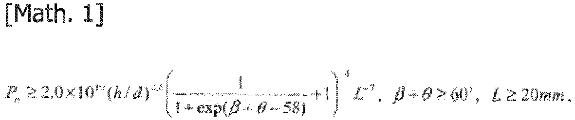
- the slit nozzle satisfies the following relational formulas: P n ⁇ 2.0 ⁇ 10 0 h / d 0.6 1 1 + exp ⁇ + ⁇ ⁇ 58 + 1 4 L ⁇ 7 , ⁇ + ⁇ ⁇ 60 ° , L ⁇ 20 mm , where gas pressure inside the slit nozzle is defined as nozzle pressure P n [KPa], an angle formed by a direction perpendicular to the surface of the sheet-like member and a jet direction of the gas is defined as a jet angle ⁇ [°], an angled formed by the jet direction of the gas and a nozzle back face that is a face disposed from the jetting port of the slit nozzle toward the downstream side in the movement direction is defined as a back face inclination angle ⁇ [°], a length of the nozzle back face in the movement direction is defined as L [mm], the gap is defined as h [mm], and a slit width of the slit nozzle is defined as d [
- the liquid removal device may further include a gap adjustment mechanism that adjusts the gap on the basis of a measurement result of the gap measurement device.
- the gap adjustment mechanism adjusts the gap to 20 mm or less.
- the gap adjustment mechanism may adjust the gap by changing a position of the slit nozzle.
- the gap adjustment mechanism adjusts the gap by changing a position of the table roll on which the sheet-like member is placed.
- the gap measurement device may measure the gap at each of measurement positions near both ends of the jetting port of the slit nozzle in a longitudinal direction.
- the gap adjustment mechanism may adjust the gap at each of the measurement positions to 20 mm or less.
- the gap measurement device may measure the gap by a laser rangefinder, for example.
- the slit nozzle may be fixed, and the sheet may move relatively to the slit nozzle by being moved in the movement direction by a conveyor device.
- the conveyor device may be a table roll on which the sheet is placed.
- the conveyor device may be a coiling/uncoiling device including a pay-off reel that uncoils the sheet-like member wound in a coil form, and a tension reel that coils, into a coil form, the sheet-like member from which the liquid has been removed.
- the sheet may be stationary, and the slit nozzle may be moved relatively to the sheet-like member by a nozzle movement mechanism.
- the slit nozzle of the liquid removal device may include a nozzle main body including the jetting port, and a gas flow channel that guides, to the jetting port, the gas that is externally supplied, and a back face member having the nozzle back face provided to extend from the jetting port of the nozzle main body toward the downstream side in the movement direction of the sheet.
- the nozzle back face may be a counter face of the back face member that faces the surface of the sheet.
- liquid on a steel sheet can be removed without using wringer rolls and a drier.
- FIG. 1 is an explanatory diagram illustrating a situation of liquid draining by a liquid removal device using a common slit nozzle 3.
- FIG. 2 is an explanatory diagram illustrating a situation of liquid draining by a liquid removal device using a slit nozzle 10 according to an embodiment of the present invention.
- a slit nozzle jets air to the surface of a steel sheet, which is a sheet-like member, to remove liquid on the steel sheet surface.
- an air blowing device that jets air from a jetting port 3a of the slit nozzle 3 to a steel sheet surface from a downstream side in a movement direction of the steel sheet that moves relatively to the liquid removal device, as illustrated in FIG. 1 , is used. As illustrated in FIG.
- a fast gas jet flow f1 jetted from the slit nozzle 3 collides with the surface of a steel sheet S, and pushes back a liquid 5a on the steel sheet S by a flow f2 toward an upstream side in the movement direction, thereby removing the liquid 5a on the steel sheet S.
- the present inventors studied a configuration of a liquid removal device that can suppress a decrease in collision pressure of the gas jet flow f1 due to interference between the outside air suction flow f4 and the reverse flow f3 after collision with the surface of the steel sheet S. Consequently, it was found that, as illustrated in FIG. 2 , when a nozzle back face 104, which is a face on the downstream side in the movement direction of the steel sheet S, is provided to extend along the surface of the steel sheet S to the downstream side in the movement direction farther than in the slit nozzle 3 illustrated in FIG. 1 , the influence of the outside air suction flow f4 due to the Coanda effect can be suppressed, and disturbance in the gas jet flow f1 can be suppressed.
- the liquid removal device according to the present embodiment is described in detail below.
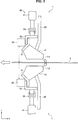
- FIG. 3 is a side view of a configuration example of the liquid removal device 1 according to the present embodiment.
- FIG. 4 is a back view of the liquid removal device 1 illustrated in FIG. 3 .
- the liquid removal device 1 is fixed and used is described. That is, the slit nozzle 10 is fixed, and the steel sheet S conveyed by a conveyor device moves relatively to the slit nozzle 10.
- the liquid removal device 1 is a device that removes liquid attached to the surface of the steel sheet S.
- the liquid removal device 1 is fixed, and the steel sheet S moves relatively to the liquid removal device 1 by being conveyed by the conveyor device.
- the movement direction of the steel sheet S that moves relatively to the liquid removal device 1 is also referred to as a conveyance direction.
- upper and lower liquid removal devices 1 are disposed to be symmetric with respect to the steel sheet S being conveyed by the conveyor device.
- the upper and lower liquid removal devices 1 may have the same configuration.
- the conveyor device that conveys the steel sheet S may be, for example, a table roll that moves the steel sheet S placed thereon by rotation.
- the conveyor device may be a coiling/uncoiling device including both end rolls provided at both ends across the liquid removal device 1 in the conveyance direction of the steel sheet S.
- the coiling/uncoiling device includes, as the both end rolls, a pay-off reel that uncoils the steel sheet S wound in a coil form, and a tension reel that coils, into a coil form, the steel sheet S from which liquid on the surface has been removed by the liquid removal device 1.
- the liquid removal device 1 includes the slit nozzle 10, a gap measurement device 30, and a gap adjustment mechanism 40.
- the slit nozzle 10 jets gas (e.g., air) externally supplied via an air supply pipe 20 to the surface of the steel sheet S from a jetting port 112 at a nozzle tip.
- the slit nozzle 10 is disposed in a manner that a slit length direction of the jetting port 112 open in a slit form corresponds to a width direction of the steel sheet S. This enables liquid on the steel sheet S to be removed over the entire width of the steel sheet S.
- the jetting port 112 is directed to the surface of the steel sheet S so as to jet gas from the downstream side toward the upstream side in the conveyance direction of the steel sheet S (i.e., from a negative direction side toward a positive direction side of an X axis).
- the slit nozzle 10 is supported by the gap adjustment mechanism 40 that brings the slit nozzle 10 close to or away from the steel sheet S, on both sides in the slit length direction (Y direction) of the jetting port 112 open in a slit form.
- the gap adjustment mechanism 40 moving the slit nozzle 10 vertically enables adjustment of a gap between the jetting port 112 and the surface of the steel sheet S.
- the slit nozzle 10 is configured in a manner that nozzle pressure, which is gas pressure inside the slit nozzle 10, and a jet angle, a back face inclination angle, a back face length, a slit width, and a gap of the slit nozzle 10 satisfy a predetermined relationship, in order to suppress the influence of the outside air suction flow f4 and suppress disturbance in the gas jet flow f1.
- nozzle pressure which is gas pressure inside the slit nozzle 10
- a jet angle, a back face inclination angle, a back face length, a slit width, and a gap of the slit nozzle 10 satisfy a predetermined relationship, in order to suppress the influence of the outside air suction flow f4 and suppress disturbance in the gas jet flow f1.
- the gap measurement device 30 measures a distance (hereinafter also referred to as "gap") between the jetting port 112 at the tip of the slit nozzle 10 and the surface of the steel sheet S. As illustrated in FIGS. 3 and 4 , the gap measurement device 30 is provided on each of both sides in the slit length direction (Y direction) of the jetting port 112 of the slit nozzle 10. Providing the gap measurement device 30 at this position makes it possible to detect an inclination of the jetting port 112 of the slit nozzle 10 with respect to the surface of the steel sheet S in the slit length direction, so that the gap can be adjusted to be constant in the slit length direction.
- the gap measurement device 30 may be provided at substantially the same position as the gap adjustment mechanism 40, which moves the slit nozzle 10 vertically, in the slit length direction, for example.
- the gap measurement device 30 includes a distance sensor 31 such as a laser rangefinder.
- the gap measurement device 30 measures the gap on the basis of, for example, a phase difference between laser light emitted to the steel sheet S and reflected light of the laser light off the surface of the steel sheet S, with the distance sensor 31 made to face the surface of the steel sheet S.
- one distance sensor 31 may be provided for each gap measurement device 30 as illustrated in FIG. 4 , or a plurality of distance sensors 31 may be provided in the slit length direction.
- the distance sensor 31 is disposed near each of both ends 112e of the jetting port 112.
- near each of the both ends 112e of the jetting port 112 refers to ranges of ⁇ 1/4w from each of the both ends 112e of the jetting port 112, where a length of the jetting port 112 of the slit nozzle 10 in the slit length direction is denoted by a slit length W.
- the distance sensor 31 since the distance sensor 31 needs to face the steel sheet S, its installation position is decided in accordance with, for example, a minimum sheet width and a maximum sheet width of the steel sheet S that can be passed in a line in which a liquid removal device 10 is installed.
- the distance sensor 31 is installed near each of the both ends 112e of the jetting port 112 so as to face the steel sheet S.
- the distance sensor 31 may be installed at a position on the inner side than an end of the steel sheet S by approximately 1/6 of a sheet width.
- the gap measurement device 30 outputs, as a gap measurement value, a gap obtained on the basis of a detection result of the distance sensor 31 to the gap adjustment mechanism 40.
- the gap adjustment mechanism 40 adjusts the gap to a predetermined size on the basis of a measurement result of the gap measurement device 30.
- the gap adjustment mechanism 40 according to the present embodiment includes a drive section 41 that moves the slit nozzle 10 vertically (in a Z direction) and a control section (not illustrated) that controls driving of the drive section 41.
- the drive section 41 is provided on each of both sides in the slit length direction (Y direction) of the jetting port 112 of the slit nozzle 10, and supports the slit nozzle 10 via support members 51, 53, and 55. Installing the drive section 41 in this manner can make the distance between the jetting port 112 and the steel sheet S in the slit length direction of the jetting port 112 uniform.
- the drive section 41 includes a cylinder, for example, and can adjust a height position of the slit nozzle 10 by moving a piston to which the support member 55 is fixed.
- the drive section 41 may be an actuator that changes a height position of a table roll on which the steel sheet S is placed, for example.
- the gap can be adjusted also by thus bringing the table roll close to or away from the jetting port 112 of the slit nozzle 10.
- the control section drives each drive section 41 in a manner that the jetting port 112 is brought as close as possible to the steel sheet S to the extent of not coming into contact with the steel sheet S, on the basis of the measurement result of the gap measurement device 30, to adjust the height position of the slit nozzle 10. Since the gap measurement value obtained by the gap measurement device 30 is a distance from the distance sensor to the surface of the steel sheet S, the control section takes a value obtained by subtracting a distance between the distance sensor and the jetting port 112 of the slit nozzle 10 from the gap measurement value as a current gap, and adjusts the height position of the slit nozzle 10 to within a predetermined range.
- Gap adjustment by the control section can cause gas jetted from the slit nozzle 10 to flow into a space between a nozzle back face of the slit nozzle 10 and the steel sheet S, making it possible to suppress the influence of the outside air suction flow (f4) on the gas jet flow (f1), as illustrated in FIG. 2 .
- the gap is preferably set to 20 mm or less by the gap adjustment mechanism 40.
- the slit nozzle 10 is configured in a manner that nozzle pressure of the slit nozzle 10, and a jet angle, a back face inclination angle, a back face length, a slit width, and a gap of the slit nozzle 10 satisfy a predetermined relationship, in order to suppress the influence of the outside air suction flow f4 and suppress disturbance in the gas jet flow f1.
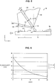
- FIG. 5 is an explanatory diagram illustrating a detailed configuration of the slit nozzle 10 according to the present embodiment.
- the slit nozzle 10 includes a nozzle front face 102 extending from the jetting port 112 toward the upstream side in the conveyance direction of the steel sheet S and the nozzle back face 104 extending from the jetting port 112 toward the downstream side in the conveyance direction of the steel sheet S.
- An inclination of the nozzle front face 102 toward the upstream side in the conveyance direction is suppressed, and the nozzle back face 104 is provided to extend along the surface of the steel sheet S toward the downstream side in the conveyance direction.
- a direction perpendicular to the surface of the steel sheet S is denoted by a reference direction C1
- an angle formed by the reference direction C1 and a gas jet direction C3 from the jetting port 112 of the slit nozzle 10 is denoted by a jet angle ⁇ [°]
- an angle formed by the reference direction C1 and the nozzle front face 102 is denoted by a front face inclination angle ⁇ [°]
- an angle formed by the gas jet direction C3 and the nozzle back face 104 is denoted by a back face inclination angle ⁇ [°].
- a length of the nozzle back face 104 in a conveyance direction C2 of the steel sheet S is denoted by a back face length L [mm].
- the liquid removal device 1 is configured to satisfy relations of the following formulas (1) to (3), where a distance between the jetting port 112 and the surface of the steel sheet S is denoted by a gap h [mm], an open width of a slit of the slit nozzle 10 is denoted by a slit width d [mm], and gas pressure inside the slit nozzle 10 is denoted by nozzle pressure P n [KPa].
- P n ⁇ F h L ⁇ ⁇ d 2.0 ⁇ 10 10 h / d 0.6 1 1 + exp ⁇ + ⁇ ⁇ 58 + 1 4 L ⁇ 7 ⁇ + ⁇ ⁇ 60 ° L ⁇ 20 mm
- the jet angle ⁇ and the back face inclination angle ⁇ indicate size, and are expressed by values of 0 or more.
- an inclination toward the upstream side in the conveyance direction of the steel sheet S and an inclination toward the downstream side are expressed respectively by a positive value and a negative value, with respect to the reference direction C1 as 0°.
- the back face length L when the nozzle back face 104 is not parallel to the steel sheet S can be calculated by L'cos(90° - ⁇ - ⁇ ), where the actual back face length is denoted by L' [mm].
- the back face length L corresponds to a length of the nozzle back face 104 in the conveyance direction (X direction) on a horizontal projection plane when the nozzle back face 104 is projected onto the horizontal projection plane.
- the above formula (1) expresses a condition for suppressing the influence of the outside air suction flow f4 and suppressing disturbance in the gas jet flow f1, which is illustrated in FIGS. 1 and 2 .
- u + (x) flow velocity of flow pulled in toward jetting port side by Coanda effect
- u - (x) flow velocity of conveyance-direction (X-direction) component of gas jet flow having collided with steel sheet
- y(x) distance between steel sheet and nozzle back face
- ⁇ pipe friction coefficient
- a velocity u+(x+dx) at a position x+dx is obtained by subtracting the obtained velocity decrease ⁇ u + (x) from a velocity u+(x) at the previous position.
- u + x + dx u + x ⁇ ⁇ u + x
- a flow velocity u_(x) of a conveyance-direction component of a gas jet flow having collided with the steel sheet is obtained by the following formula (1-4) using a flow velocity u of a gas jet flow jetted from the slit nozzle 10.
- u ⁇ x u 1 ⁇ cos ⁇ ⁇ d / y x
- a case where the flow velocity u+(L) is equal to or less than the flow velocity u - (L) (u + (L) ⁇ u - (L)) is, in other words, a case where the flow velocity u - (L) of the conveyance-direction component of the gas jet flow is equal to or greater than the flow velocity u+(L) of the flow pulled in by the Coanda effect. Therefore, the gas jet flow fl is not influenced by the flow velocity u+(L) of the flow pulled in by the Coanda effect, and does not vibrate. Consequently, the gas jet flow f1 collides with the steel sheet S without being disturbed, and liquid draining capability of the liquid removal device 1 is exhibited as illustrated in FIG. 2 .
- a case where the flow velocity u+(L) is greater than the flow velocity u - (L) (u + (L) > u - (L)) is, in other words, a case where the flow velocity u+(L) of the flow pulled in by the Coanda effect is greater than the flow velocity u - (L) of the conveyance-direction component of the gas jet flow.
- the gas jet flow f1 is influenced by the flow velocity u+(L) of the flow pulled in by the Coanda effect. Consequently, the gas jet flow f1 vibrates in the horizontal direction, and pressure of collision of the gas flow jet f1 with the steel sheet S decreases, which leads to a decrease in liquid draining capability of the liquid removal device 1 as illustrated in FIG. 1 .
- FIG. 6 shows an example of the relationship between the flow velocity u+(x) of the flow pulled in toward the jetting port 112 side by the Coanda effect and the flow velocity u_(x) of the conveyance-direction component of the gas jet flow having collided with the steel sheet S when the back face length L is set to 20 mm and the sum of the jet angle ⁇ and the back face inclination angle ⁇ is set to 90°.
- FIG. 6 shows an example of the relationship between the flow velocity u+(x) of the flow pulled in toward the jetting port 112 side by the Coanda effect and the flow velocity u_(x) of the conveyance-direction component of the gas jet flow having collided with the steel sheet S when the back face length L is set to 20 mm and the sum of the jet angle ⁇ and the back face inclination angle ⁇ is set to 90°.
- the flow velocity u_(x) of the conveyance-direction component of the gas jet flow is larger than the flow velocity u+(x) of the flow pulled in toward the jetting port 112 side by the Coanda effect. Consequently, in the case where the back face length L is 20 mm, since the flow velocity u_(x) of the conveyance-direction component of the gas jet flow is larger than the flow velocity u+(x) of the flow pulled in toward the jetting port 112 side by the Coanda effect, the flow on the nozzle back face 104 is rectified.
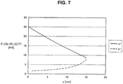
- FIG. 7 shows an example of the relationship between the flow velocity u+(x) of the flow pulled in toward the jetting port 112 side by the Coanda effect and the flow velocity u_(x) of the conveyance-direction component of the gas jet flow having collided with the steel sheet S when the back face length L is set to 15 mm and the sum of the jet angle ⁇ and the back face inclination angle ⁇ is set to 50°.
- FIG. 7 shows an example of the relationship between the flow velocity u+(x) of the flow pulled in toward the jetting port 112 side by the Coanda effect and the flow velocity u_(x) of the conveyance-direction component of the gas jet flow having collided with the steel sheet S when the back face length L is set to 15 mm and the sum of the jet angle ⁇ and the back face inclination angle ⁇ is set to 50°.
- the flow velocity u_(x) of the conveyance-direction component of the gas jet flow is smaller than the flow velocity u+(x) of the flow pulled in toward the jetting port 112 side by the Coanda effect. Therefore, in the case where the back face length L is 15 mm, since the flow velocity u_(x) of the conveyance-direction component of the gas jet flow is smaller than the flow velocity u+(x) of the flow pulled in toward the jetting port 112 side by the Coanda effect, the flow on the nozzle back face 104 becomes turbulent, so that the gas jet flow f1 is disturbed.
- the present inventors studied a configuration and setting of the liquid removal device 1 that make the flow velocity u - (L) of the conveyance-direction component of the gas jet flow equal to or greater than the flow velocity u+(L) of the flow pulled in by the Coanda effect, and consequently arrived at the relational formula of the above formula (1).
- the relational formula F(h, L, ⁇ , ⁇ , d) can be obtained by visualizing the flow on the nozzle back face 104 of the slit nozzle 10 by a tuft method, for example, and specifying the nozzle pressure P n at which the flow on the nozzle back face 104 is rectified.
- the above formula (1) was set by measuring, by a tuft method, a threshold of the nozzle pressure P n at which the flow on the nozzle back face 104 is rectified when the slid width d was set to 0.4 mm, the gap h, the back face length L, the back face inclination angle ⁇ , and the jet angle ⁇ were respectively set in ranges of 1 mm to 25 mm, 10 to 50 mm, 5 to 45°, and 0 to 75°, and the nozzle pressure P n was gradually changed from 5 to 1000KPa.
- the flow on the nozzle back face 104 was visualized by disposing polyethylene yarns with a diameter of 0.025 mm and a length of 3 mm on the nozzle back face 104 at a 5-mm pitch along the conveyance direction of the steel sheet S, and allowing the yarns to be moved by the flow on the nozzle back face 104 that changes in accordance with the nozzle pressure P n .
- the flow on the nozzle back face 104 was determined to be rectified, and the nozzle pressure P n at this time was taken as the threshold.
- the above formula (1) was obtained by performing multivariable multiple regression analysis on the gap h, the back face length L, the back face inclination angle ⁇ , and the jet angle ⁇ , in regard to each of thresholds of the nozzle pressure P n obtained by varying the gap h, the back face length L, the back face inclination angle ⁇ , and the jet angle ⁇ .
- the gap h, the back face length L, the back face inclination angle ⁇ , and the jet angle ⁇ are set as follows.
- the jet angle ⁇ and the back face inclination angle ⁇ are set in a manner that their sum is 60° or more, as expressed by the above formula (2).
- the sum of the jet angle ⁇ and the back face inclination angle ⁇ indicates an inclination state of the nozzle back face 104 with respect to the reference direction C1.
- the nozzle back face 104 is parallel to the surface of the steel sheet S.
- the sum of the jet angle ⁇ and the back face inclination angle ⁇ is set to 60° or more. Note that an upper limit of the sum of the jet angle ⁇ and the back face inclination angle ⁇ is a maximum value in a range within which the nozzle back face 104 does not come into contact with the surface of the steel sheet S.
- the nozzle back face 104 is preferably disposed to be parallel to the surface of the steel sheet S. That is, the sum of the jet angle 0 and the back face inclination angle ⁇ is preferably set to 90°.
- the reverse flow f3 toward the downstream side in the conveyance direction of the steel sheet S can smoothly flow between the nozzle back face 104 and the surface of the steel sheet S.
- the gas jet angle ⁇ is preferably set to 45°.
- gas jetted from the jetting port 112 of the slit nozzle 10 can collide at an angle of 45° from the downstream side in the conveyance direction with respect to the surface of the steel sheet S, and effectively push back the liquid 5a on the surface of the steel sheet S toward the upstream side in the conveyance direction to remove it.
- the jet angle ⁇ and the back face inclination angle ⁇ are each preferably set to 45°.
- the back face length L of the nozzle back face 104 is set to 20 mm or more as shown in the formula (3). If the back face length L is smaller than 20 mm, the outside air suction flow f4 and the reverse flow f3 collide with each other in the neighborhood of the gas jet flow f1 to disturb the gas jet flow f1. Hence, setting the back face length L to 20 mm or more prevents collision between the outside air suction flow f4 and the reverse flow f3 from occurring in the neighborhood of the gas jet flow f1, and suppresses disturbance in the gas jet flow f1 due to the outside air suction flow f4.
- the back face length L is preferably set to 20 mm or more.
- an upper limit of the back face length L of the nozzle back face 104 is not particularly limited, as long as no contact is made with another member, in terms of equipment.
- the back face length L may be up to approximately 100 mm.
- the gap h which is the distance between the jetting port 112 and the surface of the steel sheet S, is preferably set in a manner that the jetting port 112 is brought as close as possible to the steel sheet S to the extent of not coming into contact with the steel sheet S, as described above. This can cause gas jetted from the slit nozzle 10 to flow into a space between the nozzle back face of the slit nozzle 10 and the steel sheet S, making it possible to suppress the influence of the outside air suction flow f4 on the gas jet flow f1, as illustrated in FIG. 2 . To achieve this action, the gap h is preferably set to 20 mm or less, for example.
- the front face inclination angle ⁇ is not particularly limited, but may be set to 30° or less. If the front face inclination angle ⁇ is larger than 30°, the nozzle front face 102 is excessively inclined toward the upstream side in the conveyance direction; thus, after the gas jet flow f1 collides with the surface of the steel sheet S, the flow f2 toward the upstream side in the conveyance direction is likely to become a flow going toward the jetting port 112 of the slit nozzle 10 again along the nozzle front face 102, without going toward the upstream side as it is. When such a flow is formed, removal performance of the liquid 5a on the surface of the steel sheet S by the flow f2 decreases.
- the front face inclination angle ⁇ may be set to 30° or less. It is preferable that the front face inclination angle ⁇ be 0° or less. This makes it possible to more reliably prevent the flow f2 toward the upstream side in the conveyance direction from becoming a flow going toward the jetting port 112 of the slit nozzle 10 again along the nozzle front face 102.
- the slit nozzle 10 is configured and disposed so as to satisfy the above formulas (1) to (3).
- This can reduce disturbance in the gas jet flow f1 due to collision between the outside air suction flow f4 and the reverse flow f3, preventing a decrease in collision pressure when the gas jet flow f1 collides with the surface of the steel sheet S, and enabling pressure of the flow f2 toward the upstream side in the conveyance direction to be maintained. Consequently, the liquid 5a on the steel sheet S can be sufficiently removed.
- the liquid removal device 1 according to the present embodiment can sufficiently remove liquid on a steel sheet without using wringer rolls and a drier, and thus can reduce cost for maintaining equipment.
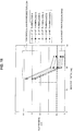
- FIG. 8 shows the relationship between the gap h and the nozzle pressure P n calculated by the above formula (1) when the jet angle ⁇ is set to 45° and the back face inclination angle ⁇ and the back face length L are changed.
- the nozzle pressure P n is equal to or greater than the value of the relational formula F(h, L, ⁇ , ⁇ , d), satisfying the relation of the above formula (1); thus, the flow on the nozzle back face 104 is rectified.
- the nozzle pressure P n is smaller than the value of the relational formula F(h, L, ⁇ , ⁇ , d), not satisfying the relation of the above formula (1). Consequently, the flow on the nozzle back face 104 becomes turbulent, and the gas jet flow f1 is disturbed.
- the sum of the back face inclination angle ⁇ and the jet angle ⁇ is 90° in cases a to c and 60° in cases d to f, both satisfying the above formula (2).
- the back face length L is 25 mm or 20 mm in cases a, b, d, and e, satisfying the above formula (3), but is 15 mm in cases c and f, not satisfying the above formula (3).
- the plot lines of cases c and f not satisfying the above formula (3) have larger slopes than the plot lines of cases a, b, d, and e satisfying the above formula (3), and a nozzle pressure P n of 200KPa or more is needed even in the case where the gap h is as close as 3 mm. If a nozzle pressure P n of 200KPa or more is needed, the pressure cannot be ensured and the liquid removal device 1 cannot be installed depending on a piping installation situation in a factory, or even if the liquid removal device 1 can be installed, a very high air flow rate is assumed to be required, leading to an increase in cost, for example. Therefore, the back face length L is preferably set to 20 mm or more.
- the plot lines of cases a, b, d, and e have similar slopes, and the above formula (1) can be satisfied even if the gap h is large or the nozzle pressure P n of the slit nozzle 10 is set smaller than 200KPa. Note that in the case where the back face length L is the same, a larger sum of the back face inclination angle ⁇ and the jet angle ⁇ can make the required nozzle pressure P n smaller.
- the slit nozzle 10 is configured and disposed so as to satisfy the above formulas (1) to (3); thus, the flow on the nozzle back face 104 can be rectified and prevented from influencing the flow of the gas jet flow f1. Consequently, a liquid removal device capable of ensuring versatility of air pressure and having an economical air flow rate can be achieved.
- the slit nozzle 10 of the liquid removal device 1 illustrated in FIG. 5 illustrates a case where an outside shape of the nozzle itself is formed so as to satisfy the above formulas (1) to (3), but the present invention is not limited to this example.
- the slit nozzle 10 of the liquid removal device 1 may include a slit nozzle (hereinafter referred to as "nozzle main body") 210 having an axisymmetric outer shape that is generally used, and a back face member 220.
- the nozzle main body 210 has a jetting port 216, which is a slit through which gas is jetted.
- a nozzle main body front face 212 and a nozzle main body back face 214 are symmetric with respect to the gas jet direction C3.
- the back face member 220 is, for example, a sheet member such as a steel sheet.
- the back face member 220 is connected to the nozzle main body back face 214, and constitutes a nozzle back face extending from the jetting port 216 of the nozzle main body 210 toward the downstream side in the conveyance direction of the steel sheet S. That is, a counter face of the back face member 220 that faces the surface of the steel sheet S serves as a nozzle back face.
- a bottom face 222 of the back face member 220 that functions as a nozzle back face is provided to extend along the surface of the steel sheet S toward the downstream side in the conveyance direction.
- This can, as with the slit nozzle 10 illustrated in FIG. 5 , reduce disturbance in the gas jet flow f1 due to collision between the outside air suction flow f4 and the reverse flow f3, preventing a decrease in collision pressure when the gas jet flow f1 collides with the surface of the steel sheet S, and enabling pressure of the flow f2 toward the upstream side in the conveyance direction to be maintained; therefore, the liquid 5a on the steel sheet S can be sufficiently removed.
- the configuration illustrated in FIG. 10 is implementable by providing the back face member 220 on the nozzle main body 210, which is an existing slit nozzle, requiring few changes to existing equipment.
- a liquid removal device with such a configuration can also sufficiently provide an effect of removing liquid on the surface of the steel sheet S.
- Liquid attached to the surface of the steel sheet S is removed by causing the slit nozzle 10 of the above-described liquid removal device 1 to face the surface of the steel sheet S and jetting gas from the slit nozzle 10 to the surface of the steel sheet S.
- a gap between the jetting port 112 of the slit nozzle 10 and the steel sheet S is measured by the gap measurement device 30.
- the gap is adjusted to 20 mm or less by changing, by driving by the drive section of the gap adjustment mechanism 40, a position of at least one of the slit nozzle 10 and the steel sheet S on the basis of the measured gap.
- the liquid attached to the surface of the steel sheet S can be removed by jetting gas from the slit nozzle 10 to the surface of the steel sheet S while relatively moving the slit nozzle 10 and the steel sheet S.
- gap measurement by the gap measurement device 30 and gap adjustment by the gap adjustment mechanism 40 may be performed for each different steel sheet S to be processed.
- the gap may be measured by the gap measurement device 30 in real time while the steel sheet S is being passed, and the gap may be adjusted to 20 mm or less by the gap adjustment mechanism 40 on the basis of the acquired gap measurement value.
- a liquid draining effect of removing liquid on a steel sheet surface was verified.
- the liquid removal device according to the present invention was installed subsequent to cleaning equipment of a continuous steel sheet processing line, and a film thickness of liquid remaining on the steel sheet surface after removal of liquid on the steel sheet surface by the liquid removal device was measured. Wringer rolls and a drier were not used. At this time, a line speed of the steel sheet was set to 100 mpm, the gap was set to 3 mm, the jet angle ⁇ was set to 45°, and the slit width d was set to 0.4 mm.
- a liquid draining effect was evaluated according to the film thickness of remaining liquid after removal of liquid on the steel sheet surface by the liquid removal device.
- liquid draining is evaluated by a visual check. Normally, as shown in FIG. 13 , remaining of liquid is visually recognized when the film thickness of the liquid on the steel sheet surface is 0.5 ⁇ m or more; hence, the steel sheet surface is determined to have a quality failure. Accordingly, a liquid draining effect was evaluated to be obtained when the film thickness of the liquid on the steel sheet surface was smaller than 0.5 ⁇ m.
- liquid draining effect: yes ( ⁇ ) indicates a case where the film thickness of the liquid on the steel sheet surface was smaller than 0.5 ⁇ m
- liquid draining effect: no ( ⁇ ) indicates a case where the film thickness of the liquid on the steel sheet surface was 0.5 ⁇ m or more.
- the sum of the jet angle ⁇ and the back face inclination angle ⁇ was 60° or more, and the slit nozzle was configured so as to satisfy the above formula (2).
- the film thickness of the liquid on the steel sheet surface was 0.5 ⁇ m or more and a sufficient liquid draining effect was not able to be obtained in cases C-1, D-1, E-1, and F-1 in which the back face length L of the nozzle back face was less than 20 mm, whereas the film thickness of the liquid on the steel sheet surface was smaller than 0.5 ⁇ m and a sufficient liquid draining effect was recognized in cases C-2, C-3, D-2, D-3, E-2, E-3, F-2, and F-3 in which the back face length L of the nozzle back face was set to 20 mm or more to satisfy the above formula (3).
- a slit nozzle configuration of the liquid removal device of the present invention can prevent occurrence of a quality failure of the steel sheet surface, and provide a sufficient liquid draining effect.
- the liquid removal device 1 including the slit nozzle 10 is fixed and the steel sheet S moves relatively to the slit nozzle 10 by being conveyed by the conveyor device, but the present invention is not limited to this example.
- the liquid removal device of the present invention is also applicable to a case where a sheet-like member is stationary, and a liquid removal device including a slit nozzle is relatively moved parallel to the sheet-like member by a nozzle movement mechanism.
Landscapes
- Chemical & Material Sciences (AREA)
- Chemical Kinetics & Catalysis (AREA)
- General Chemical & Material Sciences (AREA)
- Engineering & Computer Science (AREA)
- Materials Engineering (AREA)
- Mechanical Engineering (AREA)
- Metallurgy (AREA)
- Organic Chemistry (AREA)
- Cleaning In General (AREA)
- Cleaning And De-Greasing Of Metallic Materials By Chemical Methods (AREA)
- Cleaning By Liquid Or Steam (AREA)
- Nozzles (AREA)
Claims (10)
- Procédé d'élimination de liquide qui élimine du liquide attaché à une surface d'une tôle d'acier (S) ayant été soumise à une étape de décapage pour l'élimination de tartre, le procédé d'élimination de liquide comprenant :l'utilisation d'un dispositif d'élimination de liquide (1) comprenantune buse à fente (10) qui projette du gaz à partir d'un orifice de projection (112 ; 216) sur la surface de la tôle d'acier (S) ;un dispositif de mesure d'écartement (30) qui mesure un écartement entre l'orifice de projection (112 ; 216) de la buse à fente (10) et la tôle d'acier (S) ; etun mécanisme d'ajustement d'écartement (40) qui ajuste l'écartement sur la base d'un résultat de mesure du dispositif de mesure d'écartement (30),dans lequella buse à fente (10) est installée afin de projeter du gaz d'un côté aval vers un côté amont dans une direction de mouvement de la tôle d'acier (S) qui se déplace par rapport à la buse à fente ;la direction de mouvement de la tôle d'acier (S) est une direction horizontale ; etla buse à fente (10) satisfait les formules relationnelles suivantes :
 la pression de gaz à l'intérieur de la buse à fente (10) est définie comme pression de buse Pn [KPa] ;un angle formé par une direction perpendiculaire à la surface de la tôle d'acier (S) et une direction de jet du gaz est défini comme un angle de jet θ [°] ;un angle formé par la direction de jet du gaz et une surface arrière de buse (104) qui est une face disposée à partir de l'orifice de projection (112 ; 216) de la buse à fente (10) vers le côté aval dans la direction de mouvement est défini comme un angle d'inclinaison de face arrière β [°] ;une longueur de la face arrière de buse (104) dans la direction de mouvement est définie par L [mm] ;l'écartement est défini par h [mm] ; etune largeur de fente de la buse à fente (10) est définie par d [mm],le procédé d'élimination de liquide comprenant de plusune étape de mesure mesurant, par le dispositif de mesure d'écartement (30), un écartement entre l'orifice de projection (112 ; 216) de la buse à fente (10) et la tôle d'acier (S) ;une étape d'ajustement d'écartement ajustant l'écartement à 20 mm ou inférieur en modifiant une position d'au moins une de la buse à fente (10) et la tôle d'acier (S) sur la base de l'écartement mesuré ; etune étape d'élimination de liquide éliminant le liquide attaché à la surface de la tôle d'acier (S) par projection de gaz à partir de la buse à fente (10) sur la surface de la tôle d'acier (S) tout en déplaçant relativement la buse à fente (10) et la tôle d'acier (S).
 - Procédé d'élimination de liquide selon la revendication 1, dans lequel
la tôle d'acier (S) est déplacée dans la direction de mouvement par un rouleau de table qui achemine la tôle d'acier, et
dans l'étape d'ajustement d'écartement, le mécanisme d'ajustement d'écartement (40) ajuste l'écartement en modifiant une position du rouleau de table sur laquelle la tôle d'acier (S) est placée. - Procédé d'élimination de liquide selon la revendication 1 ou 2, dans lequel
dans l'étape de mesure, le dispositif de mesure d'écartement (30) mesure l'écartement à chacune des positions de mesure proche des deux extrémités de l'orifice de projection (112 ; 216) de la buse à fente (10) dans une direction longitudinale, et
dans l'étape d'ajustement d'écartement, le mécanisme d'ajustement d'écartement (40) ajuste l'écartement à chacune des positions de mesure à 20 mm ou inférieur. - Procédé d'élimination de liquide selon la revendication 3, dans lequel
le dispositif de mesure d'écartement (30) est un télémètre laser. - Procédé d'élimination de liquide selon l'une quelconque des revendications 1 à 4, dans lequel
la buse à fente (10) est fixe, et
la tôle d'acier (S) se déplace par rapport à la buse à fente (10) en étant déplacée dans la direction de mouvement par un dispositif d'acheminement. - Procédé d'élimination de liquide selon la revendication 5, dans lequel
le dispositif d'acheminement est un rouleau de table sur lequel la tôle d'acier (S) est placée. - Procédé d'élimination de liquide selon la revendication 5, dans lequel
le dispositif d'acheminement est un dispositif d'enroulement/ déroulement incluant une bobine de déroulement qui déroule la tôle d'acier (S) enroulée dans une forme de bobine, et une bobine de tension qui enroule, dans une forme de bobine, la tôle d'acier (S) à partir de laquelle le liquide a été éliminé. - Procédé d'élimination de liquide selon l'une quelconque des revendications 1 à 6, dans lequel
la tôle d'acier (S) est stationnaire, et
la buse à fente (10) est déplacée par rapport à la tôle d'acier (S) par un mécanisme de mouvement de buse. - Procédé d'élimination de liquide selon l'une quelconque des revendications 1 à 8, dans lequel
la buse à fente (10) inclutun corps principal de buse (210) incluant l'orifice de projection (112 ; 216) et un canal d'écoulement de gaz (110) qui guide, jusqu'à l'orifice de projection (112 ; 216), le gaz qui est fourni de manière externe, etun élément de face arrière (220) présentant la face arrière de buse (104) fournie pour s'étendre de l'orifice de projection (112 ; 216) du corps principal de buse (210) vers le côté aval dans la direction de mouvement de la tôle d'acier (S), et
la face arrière de buse (104) est une contre face de l'élément de face arrière (220) qui fait face à la surface de la tôle d'acier (S). - Procédé d'élimination de liquide selon l'une quelconque des revendications 1 à 9, dans lequel
l'écartement est réajusté en exécutant l'étape de mesure et l'étape d'ajustement d'écartement à chaque fois qu'une épaisseur de tôle de la tôle d'acier (S) change.
Applications Claiming Priority (2)
| Application Number | Priority Date | Filing Date | Title |
|---|---|---|---|
| JP2016066122 | 2016-03-29 | ||
| PCT/JP2017/012951 WO2017170714A1 (fr) | 2016-03-29 | 2017-03-29 | Appareil d'élimination de liquide et procédé d'élimination de liquide |
Publications (3)
| Publication Number | Publication Date |
|---|---|
| EP3444381A1 EP3444381A1 (fr) | 2019-02-20 |
| EP3444381A4 EP3444381A4 (fr) | 2019-12-25 |
| EP3444381B1 true EP3444381B1 (fr) | 2021-07-21 |
Family
ID=59964612
Family Applications (1)
| Application Number | Title | Priority Date | Filing Date |
|---|---|---|---|
| EP17775248.2A Active EP3444381B1 (fr) | 2016-03-29 | 2017-03-29 | Appareil d'élimination de liquide et procédé d'élimination de liquide |
Country Status (9)
| Country | Link |
|---|---|
| US (1) | US11174558B2 (fr) |
| EP (1) | EP3444381B1 (fr) |
| JP (1) | JP6402839B2 (fr) |
| KR (1) | KR102223513B1 (fr) |
| CN (1) | CN108699707B (fr) |
| BR (1) | BR112018013095B1 (fr) |
| CA (1) | CA3009318C (fr) |
| ES (1) | ES2883149T3 (fr) |
| WO (1) | WO2017170714A1 (fr) |
Families Citing this family (4)
| Publication number | Priority date | Publication date | Assignee | Title |
|---|---|---|---|---|
| WO2017213021A1 (fr) * | 2016-06-09 | 2017-12-14 | Jfeスチール株式会社 | Procédé de production d'une tôle d'acier galvanisée et dispositif de production associé |
| BE1025125B1 (fr) * | 2017-09-04 | 2018-10-31 | Centre de Recherches Métallurgiques asbl-Centrum voor Research in de Metallurgie vzw | Essuyeur sans contact et installation industrielle comportant un tel essuyeur |
| CN111940414A (zh) * | 2020-08-31 | 2020-11-17 | 合肥市商巨智能装备有限公司 | 干式超声波清洗装置及清洗方法 |
| CN119114655A (zh) * | 2024-10-21 | 2024-12-13 | 中冶南方工程技术有限公司 | 板带表面残留液清除装置及方法 |
Family Cites Families (24)
| Publication number | Priority date | Publication date | Assignee | Title |
|---|---|---|---|---|
| US3747481A (en) * | 1970-12-16 | 1973-07-24 | Inter Paper Co | Apparatus and method for handling large size corrugated paperboard panels |
| JPS5323830A (en) * | 1976-08-19 | 1978-03-04 | Seiko Instr & Electronics | Process and apparatus for automatically controlling adhesion quantity of plating |
| JPS5612316A (en) | 1979-07-09 | 1981-02-06 | Kureha Chem Ind Co Ltd | Remedy for peptic ulcer, containing morpholine derivative |
| US5014447A (en) * | 1988-02-10 | 1991-05-14 | Thermo Electron Web Systems, Inc. | Positive pressure web floater dryer with parallel flow |
| US5070628A (en) * | 1990-01-16 | 1991-12-10 | W. R. Grace & Co.-Conn. | Rotatable slot nozzle air bar |
| DE59202907D1 (de) | 1991-05-17 | 1995-08-24 | Sundwiger Eisen Maschinen | Vorrichtung zum Entfernen von Flüssigkeit von der Oberfläche eines bewegten Bandes. |
| JP3048763B2 (ja) | 1992-08-19 | 2000-06-05 | 新日本製鐵株式会社 | 鋼帯に付着する液体の除去方法 |
| JP2900969B2 (ja) * | 1993-05-31 | 1999-06-02 | 川崎製鉄株式会社 | 溶融めっきの付着量制御方法 |
| JPH10211514A (ja) * | 1997-01-29 | 1998-08-11 | Nippon Steel Corp | ルーパー機能を有するブライドル装置及びその使用方法 |
| JP3395696B2 (ja) | 1999-03-15 | 2003-04-14 | 日本電気株式会社 | ウェハ処理装置およびウェハ処理方法 |
| JP2002294478A (ja) | 2001-03-29 | 2002-10-09 | Mitsubishi Heavy Ind Ltd | 鋼帯の水切装置 |
| US6564473B2 (en) * | 2001-10-22 | 2003-05-20 | The Procter & Gamble Company | High efficiency heat transfer using asymmetric impinging jet |
| KR100641026B1 (ko) * | 2002-12-03 | 2006-11-02 | 주식회사 케이씨텍 | 슬릿형 노즐을 가지는 혼합 유체 분사 기구 |
| JP4352047B2 (ja) * | 2003-03-04 | 2009-10-28 | 三菱レイヨン株式会社 | シート状物の熱処理装置および熱処理方法 |
| JP2006122784A (ja) * | 2004-10-27 | 2006-05-18 | Sharp Corp | 基板洗浄方法および基板洗浄装置 |
| JP4720198B2 (ja) * | 2005-02-03 | 2011-07-13 | Jfeスチール株式会社 | 厚鋼板の冷却装置および冷却方法 |
| JP4330565B2 (ja) * | 2005-08-10 | 2009-09-16 | シャープ株式会社 | 基板洗浄ノズルおよび基板洗浄装置 |
| KR100758220B1 (ko) * | 2005-10-20 | 2007-09-17 | 주식회사 케이씨텍 | 다중 슬릿형 노즐을 가지는 기판 세정 장치 및 이를 이용한세정 방법 |
| JP4609392B2 (ja) | 2006-07-21 | 2011-01-12 | 住友金属工業株式会社 | 金属板材に付着した液体の除去方法及び除去装置 |
| US7697126B2 (en) * | 2008-04-02 | 2010-04-13 | Spatial Integrated Systems, Inc. | Three dimensional spatial imaging system and method |
| WO2012172648A1 (fr) * | 2011-06-14 | 2012-12-20 | 三菱日立製鉄機械株式会社 | Équipement de placage par immersion à chaud en continu |
| JP2013181196A (ja) * | 2012-03-01 | 2013-09-12 | Jfe Steel Corp | 目詰まり除去治具を備えるワイピングノズル |
| JP6205753B2 (ja) | 2013-02-28 | 2017-10-04 | 新日鐵住金株式会社 | ガスワイピングノズル及びガスワイピング方法 |
| JP6367763B2 (ja) * | 2015-06-22 | 2018-08-01 | 株式会社荏原製作所 | ウェーハ乾燥装置およびウェーハ乾燥方法 |
-
2017
- 2017-03-29 WO PCT/JP2017/012951 patent/WO2017170714A1/fr not_active Ceased
- 2017-03-29 CN CN201780013254.9A patent/CN108699707B/zh active Active
- 2017-03-29 US US16/067,371 patent/US11174558B2/en active Active
- 2017-03-29 EP EP17775248.2A patent/EP3444381B1/fr active Active
- 2017-03-29 ES ES17775248T patent/ES2883149T3/es active Active
- 2017-03-29 JP JP2018509349A patent/JP6402839B2/ja active Active
- 2017-03-29 KR KR1020187023431A patent/KR102223513B1/ko active Active
- 2017-03-29 BR BR112018013095-8A patent/BR112018013095B1/pt active IP Right Grant
- 2017-03-29 CA CA3009318A patent/CA3009318C/fr active Active
Non-Patent Citations (1)
| Title |
|---|
| None * |
Also Published As
| Publication number | Publication date |
|---|---|
| JP6402839B2 (ja) | 2018-10-10 |
| BR112018013095A2 (pt) | 2018-12-11 |
| CA3009318A1 (fr) | 2017-10-05 |
| EP3444381A1 (fr) | 2019-02-20 |
| KR102223513B1 (ko) | 2021-03-05 |
| CA3009318C (fr) | 2020-06-30 |
| CN108699707B (zh) | 2020-03-17 |
| KR20180102160A (ko) | 2018-09-14 |
| CN108699707A (zh) | 2018-10-23 |
| EP3444381A4 (fr) | 2019-12-25 |
| WO2017170714A1 (fr) | 2017-10-05 |
| BR112018013095B1 (pt) | 2023-04-18 |
| ES2883149T3 (es) | 2021-12-07 |
| US11174558B2 (en) | 2021-11-16 |
| US20180327914A1 (en) | 2018-11-15 |
| JPWO2017170714A1 (ja) | 2018-08-30 |
Similar Documents
| Publication | Publication Date | Title |
|---|---|---|
| EP3444381B1 (fr) | Appareil d'élimination de liquide et procédé d'élimination de liquide | |
| US20060060271A1 (en) | Cooling device, manufacturing method, and manufacturing line for hot rolled steel band | |
| US10465262B2 (en) | Method for cooling steel strip and cooling apparatus | |
| JP4735769B2 (ja) | スリット帯板の蛇行防止装置 | |
| JP5685861B2 (ja) | 熱鋼板の水切り装置、水切り方法および冷却設備 | |
| JP5803865B2 (ja) | ステンレス冷延鋼帯の製造方法 | |
| JP5948847B2 (ja) | 圧延装置 | |
| KR100862778B1 (ko) | 열간압연 권취설비 제어장치 | |
| JP4780246B2 (ja) | スリット帯板の蛇行防止装置 | |
| CN109719597B (zh) | 金属带的带式磨削装置以及金属带的带式磨削方法 | |
| BR112014004234B1 (pt) | dispositivo de enxugar uma folha de aço e aparelho de revestimento por imersão a quente | |
| JP7069708B2 (ja) | 水切り装置、水切り方法およびウェブの製造方法 | |
| JP2020083625A (ja) | 非接触式搬送装置における帯状基材の蛇行制御方法 | |
| JP6394913B2 (ja) | 金属帯の冷却方法 | |
| JP7533511B2 (ja) | 熱延鋼帯の製造方法 | |
| JP3632560B2 (ja) | ホットランテーブルにおける熱延鋼帯の搬送方法 | |
| JP7715110B2 (ja) | 金属板の通板時水切り装置および金属板の通板時水切り方法 | |
| JP4987672B2 (ja) | ガスワイピング装置 | |
| JPH1147812A (ja) | 熱間圧延における板反り防止方法 | |
| KR20030016433A (ko) | 표면 청정도가 우수한 열간압연강판의 제조방법 | |
| JP2012026022A (ja) | ガスワイピング装置 | |
| JP2798314B2 (ja) | 炉内シール装置 | |
| JP2024047715A (ja) | 金属板の通板時水切り装置、熱間圧延設備および熱間圧延鋼帯の製造方法 | |
| JP2019052001A (ja) | ウェブ搬送装置 | |
| JP2004001032A (ja) | 熱延鋼帯後端部の通板方法 |
Legal Events
| Date | Code | Title | Description |
|---|---|---|---|
| STAA | Information on the status of an ep patent application or granted ep patent |
Free format text: STATUS: THE INTERNATIONAL PUBLICATION HAS BEEN MADE |
|
| PUAI | Public reference made under article 153(3) epc to a published international application that has entered the european phase |
Free format text: ORIGINAL CODE: 0009012 |
|
| STAA | Information on the status of an ep patent application or granted ep patent |
Free format text: STATUS: REQUEST FOR EXAMINATION WAS MADE |
|
| 17P | Request for examination filed |
Effective date: 20180928 |
|
| AK | Designated contracting states |
Kind code of ref document: A1 Designated state(s): AL AT BE BG CH CY CZ DE DK EE ES FI FR GB GR HR HU IE IS IT LI LT LU LV MC MK MT NL NO PL PT RO RS SE SI SK SM TR |
|
| AX | Request for extension of the european patent |
Extension state: BA ME |
|
| DAV | Request for validation of the european patent (deleted) | ||
| DAX | Request for extension of the european patent (deleted) | ||
| RAP1 | Party data changed (applicant data changed or rights of an application transferred) |
Owner name: NIPPON STEEL CORPORATION |
|
| A4 | Supplementary search report drawn up and despatched |
Effective date: 20191122 |
|
| RIC1 | Information provided on ipc code assigned before grant |
Ipc: C23G 1/08 20060101AFI20191118BHEP Ipc: B21B 45/02 20060101ALI20191118BHEP Ipc: C23G 3/02 20060101ALI20191118BHEP |
|
| REG | Reference to a national code |
Ref country code: DE Ref legal event code: R079 Ref document number: 602017042541 Country of ref document: DE Free format text: PREVIOUS MAIN CLASS: C23G0003000000 Ipc: C23G0001080000 |
|
| GRAP | Despatch of communication of intention to grant a patent |
Free format text: ORIGINAL CODE: EPIDOSNIGR1 |
|
| STAA | Information on the status of an ep patent application or granted ep patent |
Free format text: STATUS: GRANT OF PATENT IS INTENDED |
|
| RIC1 | Information provided on ipc code assigned before grant |
Ipc: B21B 45/02 20060101ALI20200710BHEP Ipc: C23G 1/08 20060101AFI20200710BHEP Ipc: C23G 3/02 20060101ALI20200710BHEP |
|
| INTG | Intention to grant announced |
Effective date: 20200803 |
|
| GRAJ | Information related to disapproval of communication of intention to grant by the applicant or resumption of examination proceedings by the epo deleted |
Free format text: ORIGINAL CODE: EPIDOSDIGR1 |
|
| STAA | Information on the status of an ep patent application or granted ep patent |
Free format text: STATUS: REQUEST FOR EXAMINATION WAS MADE |
|
| INTC | Intention to grant announced (deleted) | ||
| GRAP | Despatch of communication of intention to grant a patent |
Free format text: ORIGINAL CODE: EPIDOSNIGR1 |
|
| STAA | Information on the status of an ep patent application or granted ep patent |
Free format text: STATUS: GRANT OF PATENT IS INTENDED |
|
| INTG | Intention to grant announced |
Effective date: 20210203 |
|
| GRAS | Grant fee paid |
Free format text: ORIGINAL CODE: EPIDOSNIGR3 |
|
| GRAA | (expected) grant |
Free format text: ORIGINAL CODE: 0009210 |
|
| STAA | Information on the status of an ep patent application or granted ep patent |
Free format text: STATUS: THE PATENT HAS BEEN GRANTED |
|
| AK | Designated contracting states |
Kind code of ref document: B1 Designated state(s): AL AT BE BG CH CY CZ DE DK EE ES FI FR GB GR HR HU IE IS IT LI LT LU LV MC MK MT NL NO PL PT RO RS SE SI SK SM TR |
|
| REG | Reference to a national code |
Ref country code: GB Ref legal event code: FG4D |
|
| REG | Reference to a national code |
Ref country code: CH Ref legal event code: EP |
|
| REG | Reference to a national code |
Ref country code: DE Ref legal event code: R096 Ref document number: 602017042541 Country of ref document: DE |
|
| REG | Reference to a national code |
Ref country code: AT Ref legal event code: REF Ref document number: 1412693 Country of ref document: AT Kind code of ref document: T Effective date: 20210815 |
|
| REG | Reference to a national code |
Ref country code: IE Ref legal event code: FG4D |
|
| REG | Reference to a national code |
Ref country code: LT Ref legal event code: MG9D |
|
| REG | Reference to a national code |
Ref country code: NL Ref legal event code: MP Effective date: 20210721 |
|
| REG | Reference to a national code |
Ref country code: ES Ref legal event code: FG2A Ref document number: 2883149 Country of ref document: ES Kind code of ref document: T3 Effective date: 20211207 |
|
| PG25 | Lapsed in a contracting state [announced via postgrant information from national office to epo] |
Ref country code: LT Free format text: LAPSE BECAUSE OF FAILURE TO SUBMIT A TRANSLATION OF THE DESCRIPTION OR TO PAY THE FEE WITHIN THE PRESCRIBED TIME-LIMIT Effective date: 20210721 Ref country code: BG Free format text: LAPSE BECAUSE OF FAILURE TO SUBMIT A TRANSLATION OF THE DESCRIPTION OR TO PAY THE FEE WITHIN THE PRESCRIBED TIME-LIMIT Effective date: 20211021 Ref country code: PT Free format text: LAPSE BECAUSE OF FAILURE TO SUBMIT A TRANSLATION OF THE DESCRIPTION OR TO PAY THE FEE WITHIN THE PRESCRIBED TIME-LIMIT Effective date: 20211122 Ref country code: NO Free format text: LAPSE BECAUSE OF FAILURE TO SUBMIT A TRANSLATION OF THE DESCRIPTION OR TO PAY THE FEE WITHIN THE PRESCRIBED TIME-LIMIT Effective date: 20211021 Ref country code: NL Free format text: LAPSE BECAUSE OF FAILURE TO SUBMIT A TRANSLATION OF THE DESCRIPTION OR TO PAY THE FEE WITHIN THE PRESCRIBED TIME-LIMIT Effective date: 20210721 Ref country code: FI Free format text: LAPSE BECAUSE OF FAILURE TO SUBMIT A TRANSLATION OF THE DESCRIPTION OR TO PAY THE FEE WITHIN THE PRESCRIBED TIME-LIMIT Effective date: 20210721 Ref country code: HR Free format text: LAPSE BECAUSE OF FAILURE TO SUBMIT A TRANSLATION OF THE DESCRIPTION OR TO PAY THE FEE WITHIN THE PRESCRIBED TIME-LIMIT Effective date: 20210721 Ref country code: SE Free format text: LAPSE BECAUSE OF FAILURE TO SUBMIT A TRANSLATION OF THE DESCRIPTION OR TO PAY THE FEE WITHIN THE PRESCRIBED TIME-LIMIT Effective date: 20210721 Ref country code: RS Free format text: LAPSE BECAUSE OF FAILURE TO SUBMIT A TRANSLATION OF THE DESCRIPTION OR TO PAY THE FEE WITHIN THE PRESCRIBED TIME-LIMIT Effective date: 20210721 |
|
| PG25 | Lapsed in a contracting state [announced via postgrant information from national office to epo] |
Ref country code: PL Free format text: LAPSE BECAUSE OF FAILURE TO SUBMIT A TRANSLATION OF THE DESCRIPTION OR TO PAY THE FEE WITHIN THE PRESCRIBED TIME-LIMIT Effective date: 20210721 Ref country code: LV Free format text: LAPSE BECAUSE OF FAILURE TO SUBMIT A TRANSLATION OF THE DESCRIPTION OR TO PAY THE FEE WITHIN THE PRESCRIBED TIME-LIMIT Effective date: 20210721 Ref country code: GR Free format text: LAPSE BECAUSE OF FAILURE TO SUBMIT A TRANSLATION OF THE DESCRIPTION OR TO PAY THE FEE WITHIN THE PRESCRIBED TIME-LIMIT Effective date: 20211022 |
|
| REG | Reference to a national code |
Ref country code: DE Ref legal event code: R097 Ref document number: 602017042541 Country of ref document: DE |
|
| PG25 | Lapsed in a contracting state [announced via postgrant information from national office to epo] |
Ref country code: DK Free format text: LAPSE BECAUSE OF FAILURE TO SUBMIT A TRANSLATION OF THE DESCRIPTION OR TO PAY THE FEE WITHIN THE PRESCRIBED TIME-LIMIT Effective date: 20210721 |
|
| PLBE | No opposition filed within time limit |
Free format text: ORIGINAL CODE: 0009261 |
|
| STAA | Information on the status of an ep patent application or granted ep patent |
Free format text: STATUS: NO OPPOSITION FILED WITHIN TIME LIMIT |
|
| PG25 | Lapsed in a contracting state [announced via postgrant information from national office to epo] |
Ref country code: SM Free format text: LAPSE BECAUSE OF FAILURE TO SUBMIT A TRANSLATION OF THE DESCRIPTION OR TO PAY THE FEE WITHIN THE PRESCRIBED TIME-LIMIT Effective date: 20210721 Ref country code: SK Free format text: LAPSE BECAUSE OF FAILURE TO SUBMIT A TRANSLATION OF THE DESCRIPTION OR TO PAY THE FEE WITHIN THE PRESCRIBED TIME-LIMIT Effective date: 20210721 Ref country code: RO Free format text: LAPSE BECAUSE OF FAILURE TO SUBMIT A TRANSLATION OF THE DESCRIPTION OR TO PAY THE FEE WITHIN THE PRESCRIBED TIME-LIMIT Effective date: 20210721 Ref country code: EE Free format text: LAPSE BECAUSE OF FAILURE TO SUBMIT A TRANSLATION OF THE DESCRIPTION OR TO PAY THE FEE WITHIN THE PRESCRIBED TIME-LIMIT Effective date: 20210721 Ref country code: CZ Free format text: LAPSE BECAUSE OF FAILURE TO SUBMIT A TRANSLATION OF THE DESCRIPTION OR TO PAY THE FEE WITHIN THE PRESCRIBED TIME-LIMIT Effective date: 20210721 Ref country code: AL Free format text: LAPSE BECAUSE OF FAILURE TO SUBMIT A TRANSLATION OF THE DESCRIPTION OR TO PAY THE FEE WITHIN THE PRESCRIBED TIME-LIMIT Effective date: 20210721 |
|
| 26N | No opposition filed |
Effective date: 20220422 |
|
| PG25 | Lapsed in a contracting state [announced via postgrant information from national office to epo] |
Ref country code: IT Free format text: LAPSE BECAUSE OF FAILURE TO SUBMIT A TRANSLATION OF THE DESCRIPTION OR TO PAY THE FEE WITHIN THE PRESCRIBED TIME-LIMIT Effective date: 20210721 |
|
| PG25 | Lapsed in a contracting state [announced via postgrant information from national office to epo] |
Ref country code: MC Free format text: LAPSE BECAUSE OF FAILURE TO SUBMIT A TRANSLATION OF THE DESCRIPTION OR TO PAY THE FEE WITHIN THE PRESCRIBED TIME-LIMIT Effective date: 20210721 |
|
| REG | Reference to a national code |
Ref country code: CH Ref legal event code: PL |
|
| GBPC | Gb: european patent ceased through non-payment of renewal fee |
Effective date: 20220329 |
|
| PG25 | Lapsed in a contracting state [announced via postgrant information from national office to epo] |
Ref country code: LU Free format text: LAPSE BECAUSE OF NON-PAYMENT OF DUE FEES Effective date: 20220329 Ref country code: LI Free format text: LAPSE BECAUSE OF NON-PAYMENT OF DUE FEES Effective date: 20220331 Ref country code: IE Free format text: LAPSE BECAUSE OF NON-PAYMENT OF DUE FEES Effective date: 20220329 Ref country code: GB Free format text: LAPSE BECAUSE OF NON-PAYMENT OF DUE FEES Effective date: 20220329 Ref country code: CH Free format text: LAPSE BECAUSE OF NON-PAYMENT OF DUE FEES Effective date: 20220331 |
|
| REG | Reference to a national code |
Ref country code: AT Ref legal event code: UEP Ref document number: 1412693 Country of ref document: AT Kind code of ref document: T Effective date: 20210721 |
|
| PG25 | Lapsed in a contracting state [announced via postgrant information from national office to epo] |
Ref country code: HU Free format text: LAPSE BECAUSE OF FAILURE TO SUBMIT A TRANSLATION OF THE DESCRIPTION OR TO PAY THE FEE WITHIN THE PRESCRIBED TIME-LIMIT; INVALID AB INITIO Effective date: 20170329 |
|
| PG25 | Lapsed in a contracting state [announced via postgrant information from national office to epo] |
Ref country code: MK Free format text: LAPSE BECAUSE OF FAILURE TO SUBMIT A TRANSLATION OF THE DESCRIPTION OR TO PAY THE FEE WITHIN THE PRESCRIBED TIME-LIMIT Effective date: 20210721 Ref country code: CY Free format text: LAPSE BECAUSE OF FAILURE TO SUBMIT A TRANSLATION OF THE DESCRIPTION OR TO PAY THE FEE WITHIN THE PRESCRIBED TIME-LIMIT Effective date: 20210721 |
|
| PG25 | Lapsed in a contracting state [announced via postgrant information from national office to epo] |
Ref country code: MT Free format text: LAPSE BECAUSE OF FAILURE TO SUBMIT A TRANSLATION OF THE DESCRIPTION OR TO PAY THE FEE WITHIN THE PRESCRIBED TIME-LIMIT Effective date: 20210721 |
|
| PGFP | Annual fee paid to national office [announced via postgrant information from national office to epo] |
Ref country code: ES Payment date: 20250403 Year of fee payment: 9 |
|
| PG25 | Lapsed in a contracting state [announced via postgrant information from national office to epo] |
Ref country code: TR Free format text: LAPSE BECAUSE OF FAILURE TO SUBMIT A TRANSLATION OF THE DESCRIPTION OR TO PAY THE FEE WITHIN THE PRESCRIBED TIME-LIMIT Effective date: 20210721 |
|
| PGFP | Annual fee paid to national office [announced via postgrant information from national office to epo] |
Ref country code: DE Payment date: 20260204 Year of fee payment: 10 |
|
| PGFP | Annual fee paid to national office [announced via postgrant information from national office to epo] |
Ref country code: AT Payment date: 20260225 Year of fee payment: 10 |
|
| PGFP | Annual fee paid to national office [announced via postgrant information from national office to epo] |
Ref country code: BE Payment date: 20260217 Year of fee payment: 10 |
|
| PGFP | Annual fee paid to national office [announced via postgrant information from national office to epo] |
Ref country code: FR Payment date: 20260209 Year of fee payment: 10 |