EP3444469B1 - Mechanismus zur einschränkung der kraftstoffdruckpulsation und hochdruckbrennstoffpumpe eines verbrennungsmotors mit solch einem mechanismus - Google Patents
Mechanismus zur einschränkung der kraftstoffdruckpulsation und hochdruckbrennstoffpumpe eines verbrennungsmotors mit solch einem mechanismus Download PDFInfo
- Publication number
- EP3444469B1 EP3444469B1 EP18191492.0A EP18191492A EP3444469B1 EP 3444469 B1 EP3444469 B1 EP 3444469B1 EP 18191492 A EP18191492 A EP 18191492A EP 3444469 B1 EP3444469 B1 EP 3444469B1
- Authority
- EP
- European Patent Office
- Prior art keywords
- damper
- holding member
- pump housing
- fuel
- high pressure
- Prior art date
- Legal status (The legal status is an assumption and is not a legal conclusion. Google has not performed a legal analysis and makes no representation as to the accuracy of the status listed.)
- Active
Links
Images




Classifications
-
- F—MECHANICAL ENGINEERING; LIGHTING; HEATING; WEAPONS; BLASTING
- F04—POSITIVE - DISPLACEMENT MACHINES FOR LIQUIDS; PUMPS FOR LIQUIDS OR ELASTIC FLUIDS
- F04B—POSITIVE-DISPLACEMENT MACHINES FOR LIQUIDS; PUMPS
- F04B53/00—Component parts, details or accessories not provided for in, or of interest apart from, groups F04B1/00 - F04B23/00 or F04B39/00 - F04B47/00
- F04B53/16—Casings; Cylinders; Cylinder liners or heads; Fluid connections
-
- F—MECHANICAL ENGINEERING; LIGHTING; HEATING; WEAPONS; BLASTING
- F02—COMBUSTION ENGINES; HOT-GAS OR COMBUSTION-PRODUCT ENGINE PLANTS
- F02M—SUPPLYING COMBUSTION ENGINES IN GENERAL WITH COMBUSTIBLE MIXTURES OR CONSTITUENTS THEREOF
- F02M37/00—Apparatus or systems for feeding liquid fuel from storage containers to carburettors or fuel-injection apparatus; Arrangements for purifying liquid fuel specially adapted for, or arranged on, internal-combustion engines
- F02M37/0011—Constructional details; Manufacturing or assembly of elements of fuel systems; Materials therefor
- F02M37/0041—Means for damping pressure pulsations
-
- F—MECHANICAL ENGINEERING; LIGHTING; HEATING; WEAPONS; BLASTING
- F02—COMBUSTION ENGINES; HOT-GAS OR COMBUSTION-PRODUCT ENGINE PLANTS
- F02M—SUPPLYING COMBUSTION ENGINES IN GENERAL WITH COMBUSTIBLE MIXTURES OR CONSTITUENTS THEREOF
- F02M55/00—Fuel-injection apparatus characterised by their fuel conduits or their venting means; Arrangements of conduits between fuel tank and pump F02M37/00
- F02M55/04—Means for damping vibrations or pressure fluctuations in injection pump inlets or outlets
-
- F—MECHANICAL ENGINEERING; LIGHTING; HEATING; WEAPONS; BLASTING
- F02—COMBUSTION ENGINES; HOT-GAS OR COMBUSTION-PRODUCT ENGINE PLANTS
- F02M—SUPPLYING COMBUSTION ENGINES IN GENERAL WITH COMBUSTIBLE MIXTURES OR CONSTITUENTS THEREOF
- F02M59/00—Pumps specially adapted for fuel-injection and not provided for in groups F02M39/00 -F02M57/00, e.g. rotary cylinder-block type of pumps
- F02M59/44—Details, components parts, or accessories not provided for in, or of interest apart from, the apparatus of groups F02M59/02 - F02M59/42; Pumps having transducers, e.g. to measure displacement of pump rack or piston
- F02M59/442—Details, components parts, or accessories not provided for in, or of interest apart from, the apparatus of groups F02M59/02 - F02M59/42; Pumps having transducers, e.g. to measure displacement of pump rack or piston means preventing fuel leakage around pump plunger, e.g. fluid barriers
-
- F—MECHANICAL ENGINEERING; LIGHTING; HEATING; WEAPONS; BLASTING
- F02—COMBUSTION ENGINES; HOT-GAS OR COMBUSTION-PRODUCT ENGINE PLANTS
- F02M—SUPPLYING COMBUSTION ENGINES IN GENERAL WITH COMBUSTIBLE MIXTURES OR CONSTITUENTS THEREOF
- F02M59/00—Pumps specially adapted for fuel-injection and not provided for in groups F02M39/00 -F02M57/00, e.g. rotary cylinder-block type of pumps
- F02M59/44—Details, components parts, or accessories not provided for in, or of interest apart from, the apparatus of groups F02M59/02 - F02M59/42; Pumps having transducers, e.g. to measure displacement of pump rack or piston
- F02M59/48—Assembling; Disassembling; Replacing
-
- F—MECHANICAL ENGINEERING; LIGHTING; HEATING; WEAPONS; BLASTING
- F04—POSITIVE - DISPLACEMENT MACHINES FOR LIQUIDS; PUMPS FOR LIQUIDS OR ELASTIC FLUIDS
- F04B—POSITIVE-DISPLACEMENT MACHINES FOR LIQUIDS; PUMPS
- F04B11/00—Equalisation of pulses, e.g. by use of air vessels; Counteracting cavitation
- F04B11/0008—Equalisation of pulses, e.g. by use of air vessels; Counteracting cavitation using accumulators
- F04B11/0033—Equalisation of pulses, e.g. by use of air vessels; Counteracting cavitation using accumulators with a mechanical spring
-
- F—MECHANICAL ENGINEERING; LIGHTING; HEATING; WEAPONS; BLASTING
- F04—POSITIVE - DISPLACEMENT MACHINES FOR LIQUIDS; PUMPS FOR LIQUIDS OR ELASTIC FLUIDS
- F04B—POSITIVE-DISPLACEMENT MACHINES FOR LIQUIDS; PUMPS
- F04B39/00—Component parts, details, or accessories, of pumps or pumping systems specially adapted for elastic fluids, not otherwise provided for in, or of interest apart from, groups F04B25/00 - F04B37/00
- F04B39/12—Casings; Cylinders; Cylinder heads; Fluid connections
- F04B39/122—Cylinder block
-
- F—MECHANICAL ENGINEERING; LIGHTING; HEATING; WEAPONS; BLASTING
- F04—POSITIVE - DISPLACEMENT MACHINES FOR LIQUIDS; PUMPS FOR LIQUIDS OR ELASTIC FLUIDS
- F04B—POSITIVE-DISPLACEMENT MACHINES FOR LIQUIDS; PUMPS
- F04B39/00—Component parts, details, or accessories, of pumps or pumping systems specially adapted for elastic fluids, not otherwise provided for in, or of interest apart from, groups F04B25/00 - F04B37/00
- F04B39/12—Casings; Cylinders; Cylinder heads; Fluid connections
- F04B39/123—Fluid connections
-
- F—MECHANICAL ENGINEERING; LIGHTING; HEATING; WEAPONS; BLASTING
- F04—POSITIVE - DISPLACEMENT MACHINES FOR LIQUIDS; PUMPS FOR LIQUIDS OR ELASTIC FLUIDS
- F04B—POSITIVE-DISPLACEMENT MACHINES FOR LIQUIDS; PUMPS
- F04B39/00—Component parts, details, or accessories, of pumps or pumping systems specially adapted for elastic fluids, not otherwise provided for in, or of interest apart from, groups F04B25/00 - F04B37/00
- F04B39/12—Casings; Cylinders; Cylinder heads; Fluid connections
- F04B39/125—Cylinder heads
Definitions
- the present invention relates to a mechanism for reducing pressure pulsation which is housed in a damper chamber provided in a low pressure fuel passage leading to a pressure chamber of a high pressure fuel supply pump.
- the present invention also relates to a high pressure fuel supply pump of an internal combustion engine integrally including such a mechanism for reducing pressure pulsation.
- a conventional mechanism for reducing fuel pressure pulsation is configured to hold a metal damper which is formed by joining two metal diaphragms and sealing gas inside the two metal diaphragms, between a damper chamber provided in a pump main body and a cover fitted onto the main body, and is housed in the damper chamber formed in a low pressure fuel passage leading to a pressure chamber of a high pressure fuel supply pump.
- two metal diaphragms are welded at their outer peripheries, have a disk-shaped convex portion with gas sealed in a center, and include an annular flat plate portion in which the two metal diaphragms are superimposed on each other, between the weld portion at the outer periphery and the disk-shaped convex portion.
- a damper mechanism in which both outer surfaces of the flat plate portion are held by thick portions provided at a cover and a main body, or a damper mechanism in which elastic members are sandwiched between the cover and the annular flat plate portion and between the main body and the annular flat portion to hold them.
- high pressure fuel supply pumps including such mechanisms for reducing fuel pressure pulsation (see JP-A-2004-138071 , JP-A-2006-521487 , JP-A-2003-254191 and JP-A-2005-42554 ).
- DE 10 2004 047601 A1 a high pressure fuel supply pump is described with a housing having an inlet.
- WO 2005/031161 A2 discloses a high-pressure fuel pump, comprising a housing and at least one low-pressure connection on the intake side.
- the fluid pump further comprises a pressure damper which dampens pressure variations on the intake side while encompassing at least one compressible volume that is located directly in the flow path between the low-pressure connection and the intake valve.
- An object of the present invention is to reduce the number of components at the time of operation of installing a metal diaphragm damper as a damper mechanism for reducing pressure pulsation into a low pressure fuel passage and prevent component omission and assembly error.
- an object of the present invention is to reduce the number of components at the time of assembling a damper mechanism for reducing pressure pulsation to a high pressure fuel supply pump, and prevent component omission and assembly error in the high pressure fuel supply pump including the damper mechanism for reducing pressure pulsation.
- a high pressure fuel pump comprising a pump housing, a pressure chamber provided in the pump housing, a damper chamber formed by the pump housing and a damper cover.
- a metal diaphragm damper is arranged in the damper chamber and a pair of an upper holding member and a lower holding member are vertically sandwiching the metal diaphragm damper.
- the upper holding member is in contact with the damper cover, and the lower holding member is in contact with the pump housing.
- a recess end surface of the pump housing and the lower holding member are in contact with each other, wherein the weld portion is fixing the damper cover to the pump housing at an entire circumference of the press-fitting portion, for being liquid-tightly fixed by applying welding to the entire circumference at a weld portion.
- an annular surface of the damper cover is temporarily press-fitted to an annular surface of the pump housing, wherein at this timing, a projected portion of the damper cover and the upper holding member are already in contact with each other at the contact portion, and wherein the weld portion penetrates through the damper cover to the pump housing at an entire circumference of the press-fitting portion.
- a method for manufacturing a high pressure fuel pump comprising a pump housing, a pressure chamber provided in the pump housing, a damper chamber formed by the pump housing and a damper cover.
- a metal diaphragm damper is arranged in the damper chamber, and a pair of an upper holding member and a lower holding member are vertically sandwiching the metal diaphragm damper.
- the upper holding member is in contact with the damper cover and the lower holding member is in contact with the pump housing.
- an annular surface of the damper cover is temporarily press-fitted to an annular surface of the pump housing, wherein at this timing, a projected portion of the damper cover and the upper holding member are already in contact with each other at the contact portion.
- the weld portion is fixing the damper cover to the pump housing at an entire circumference of the press-fitting portion for being liquid-tightly fixed by applying welding to the entire circumference at a weld portion, and the weld portion penetrates through the damper cover to the pump housing at an entire circumference of the press-fitting portion.
- component omission and assembly error can be prevented by reducing the number of components which are installed or fixed into a body at the same time at a time of operation of installing a metal diaphragm damper as a damper mechanism for reducing pressure pulsation in a low pressure fuel passage or a high pressure fuel supply pump.
- Fig. 1 shows a fuel supply system including a high pressure fuel supply pump.
- Fig. 2 shows a vertical sectional view of the high pressure fuel supply pump.
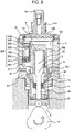
- Fig. 3 shows a vertical sectional view in a direction perpendicular to Fig. 2 .
- Fig. 1 the part enclosed by the broken line shows a pump housing 1 of a high pressure pump, and shows that a damper mechanism and components shown inside the broken line are integrally installed in the pump housing 1 of the high pressure pump.
- a fuel of a fuel tank 20 is pumped up by a feed pump 21 based on a signal from an engine control unit 27 (hereinafter, called an ECU), and pressurized to a suitable feed pressure to be fed to a intake port 10a of the high pressure fuel supply pump through a intake pipe 28.
- an engine control unit 27 hereinafter, called an ECU
- the fuel passing through the intake port 10a passes through a filter 102 fixed inside a intake joint 101, and further through a metal diaphragm damper 9, and intake passages 10b and 10c to reach a intake port 30a of an electromagnetic intake valve mechanism 30 configuring a variable fuel discharge amount control mechanism.
- the intake filter 102 in the intake joint 101 has the function of preventing foreign matters existing in the area from the fuel tank 20 to the intake port 10a from being absorbed into a high pressure fuel supply pump by flow of a fuel.
- the electromagnetic intake valve mechanism 30 includes an electromagnetic coil 30b, and in the state in which the electromagnetic coil 30b is energized, the state in which a spring 33 is compressed is kept with an electromagnetic plunger 30c being moved rightward in Fig. 1 .
- a intake valve member 31 mounted to a tip end of the electromagnetic plunger 30c opens a intake port 32 connecting to a pressure chamber 11 of the high pressure pump.
- the intake valve member 31 is overcome the biasing force of the spring 33, and open the intake port 32, by valve opening force due to the fluid pressure difference.
- the volume of the pressure chamber 11 decreases with compression movement of the plunger 2, but in this state, the fuel which is once sucked into the pressure chamber 11 is spilled to the intake passage 10c (intake port 30a) through the intake valve member 31 in the valve open state again, and therefore, the pressure of the pressure chamber does not rise.
- This process is called a spill process.
- the magnetic biasing force acting on the electromagnetic plunger 30c is erased after a lapse of a specified time (after the lapse of magnetic and mechanical delay time).
- the biasing force by the spring 33 works on the intake valve member 31, and therefore, when the magnetic force acting on the electromagnetic plunger 30c disappears, the intake valve member 31 closes the intake port 32 by the biasing force by the spring 33.
- the intake port 32 is closed, the fuel pressure of the pressure chamber 11 rises with the rising movement of the plunger 2 from this time.
- the amount of the high pressure fuel to be discharged can be controlled.
- the ratio of the spill process is large and the ratio of the discharge process is small during the compression process. Specifically, more fuel is spilled to the intake passage 10c, and less fuel is discharged at a high pressure.
- the timing of canceling energization to the electromagnetic coil 30c is controlled by the command from the ECU.
- the timing of canceling energization to the electromagnetic coil 30c is controlled, and thereby the amount of the fuel which is discharged at a high pressure can be controlled to the amount required by the internal combustion engine.
- the fuel introduced into the fuel intake port 10a is introduced into the pressure chamber 11 of the pump housing 1, and the required amount is pressurized to a high pressure by reciprocating movement of the plunger 2, and is pressure-fed to the common rail 23 from the fuel discharge port 12.
- An injector 24 and a pressure sensor 26 are provided to the common rail 23.
- the injectors 24 the number of which corresponds to the number of cylinders of the internal combustion engine are provided, and open and close in accordance with the control signal of the engine control unit (ECU) 27 to inject a fuel into the cylinders.
- ECU engine control unit
- a concave portion 1A as the pressure chamber 11 is formed in a center, and a hole 11A for fixing the discharge valve mechanism 8 is formed in an area from the inner peripheral wall of the pressure chamber 11 to the discharge port 12. Further, a hole 30A for mounting the electromagnetic intake valve mechanism 30 for supplying a fuel to the pressure chamber 11 is provided in an outer wall of the pump housing on the same axial line as the hole 11a for fixing the discharge valve mechanism 8.
- the axial lines of the hole 11a for fixing the discharge valve mechanism 8 and the hole for mounting the electromagnetic intake valve mechanism 30 are formed in the direction orthogonal to the center axial line of the concave portion 1A as the pressure chamber 11, and the discharge valve mechanism 8 for discharging the fuel to the discharge passage from the pressure chamber 11 is provided.
- the cylinder 6 which guides the reciprocating movement of the plunger 2 is protrude to the pressure chamber.
- the axial lines of the hole 11a for fitting the discharge valve mechanism 8 and the hole 30A for mounting the electromagnetic intake valve mechanism 30 are formed to be the same axial line, but according to this, assembly can be performed straight from the hole 30A for mounting the electromagnetic intake valve mechanism 30 to the hole 11a for fitting the discharge valve mechanism 8.
- the force at the time of press-fitting the discharge valve mechanism 8 can be applied from the hole 30A for mounting the electromagnetic intake valve mechanism 30.
- the diameter of the hole 30A in the minimum diameter portion needs to be configured to be larger than the maximum outside diameter of the discharge valve mechanism 8.
- the discharge valve mechanism 8 is provided at an outlet of the pressure chamber 11.
- the discharge valve mechanism 8 is composed of a seat member (seat member) 8a, a discharge valve 8b, a discharge valve spring 8c and a holding member 8d as a discharge valve stopper.
- the discharge valve 8b In the state without a pressure difference in the fuel between the pressure chamber 11 and the discharge port 12, the discharge valve 8b is in pressure-contact with the seat member 8a by the biasing force by the discharge valve spring 8c and is in the valve closed state. It is not until the fuel pressure in the pressure chamber 11 becomes larger than the fuel pressure of the discharge port 12 by a specific value that the discharge valve 8b opens against the discharge valve spring 8c, and the fuel in the pressure chamber 11 is discharged to the common rail 23 through the discharge port 12.
- the discharge valve 8b When the discharge valve 8b opens, the discharge valve 8b contacts the holding member 8d, and its movement is restricted. Accordingly, the stroke of the discharge valve 8b is properly determined by the holding member 8d. If the stroke is too large, the fuel discharged to the fuel discharge port 12 flows back into the pressure chamber 11 again due to delay in closure of the discharge valve 8b, and therefore, the efficiency as the high pressure pump reduces. Further, the holding member 8d guides the discharge valve 8b so that the discharge valve 8b moves only in the stroke (axial) direction when the discharge valve 8b repeats opening and closing movement. By being configured as above, the discharge valve mechanism 8 functions as a check-valve which restricts the flowing direction of the fuel.
- the high pressure fuel supply pump is fixed to the engine by a flange holder 40, a flange 41 and a bush 43.
- the flange holder 40 is pressure-contacted and fixed to the engine by a set screw 42 via the flange 41.
- the bush 43 exists between the flange 41 and the engine.
- the flange holder 40 is fixed to the pump housing 1 by a screw threaded in an inner periphery, and therefore, the pump housing is fixed to the engine by this.
- the bush 43 is fixed to the flange 41, whereby the flange 41 can be formed into a flat shape without a curved portion as shown in Fig. 2 . Thereby, formation of the flange 41 is facilitated.
- the pump housing 1 is further provided with a relief passage 311 which allows a downstream side of the discharge valve 8b and the intake passage 10c to communicate with.
- the relief passage 311 is provided with a relief valve mechanism 200 which restricts the flow of the fuel to only one direction from the discharge passage to the intake passage 10c, and an inlet of the relief valve mechanism 200 communicates with the downstream side of the discharge valve 8b by a passage not illustrated.
- a relief valve 202 is pressed against a relief valve seat 201 by a relief spring 204 which generates a pressing force, and a set valve opening pressure is set so that when the pressure difference between the inside of the intake chamber and the inside of the relief passage becomes a specified pressure or more, the relief valve 202 separates from the relief valve seat 201 to open.
- the pressure when the relief valve 202 starts to open is defined as the set valve opening pressure.
- the relief valve mechanism 200 is composed of a relief valve housing 206 integrated with the relief valve seat 201, the relief valve 202, a relief presser 203, the relief spring 204 and a relief spring adjuster 205.
- the relief valve mechanism 200 is assembled outside the pump housing 1 as a subassembly, and thereafter, is fixed to the pump housing 1 by press-fitting.
- the relief valve 202, the relief presser 203 and the relief spring 204 are sequentially inserted into the relief valve housing 206, and the relief spring adjuster 205 is fixed to the relief valve housing 206 by press-fitting.
- the set load of the relief spring 204 is determined by the fixing position of the relief spring adjuster 205.
- the valve opening pressure of the relief valve 202 is determined by the set load of the relief spring 204.
- the relief subassembly 200 thus constructed is fixed to the pump housing 1 by press-fitting.
- valve opening pressure of the relief valve 200 is set to a pressure higher than the maximum pressure in the normal operation range of the high pressure fuel supply pump.
- the abnormal high pressure in the common rail 23 which occurs due to a failure of a fuel injection valve which supplies a fuel to the engine, and a failure of the ECU 27 or the like which controls the fuel injection valve, the high pressure fuel supply pump and the like becomes the predetermined valve opening pressure of the relief valve or higher, the fuel passes through the relief passage 211 from the downstream side of the discharge valve 8b and reaches the relief valve 202.
- the fuel which passes through the relief valve 202 is released to the intake passage 10c which is the low pressure portion of a relief passage 208 which is provided in the relief spring adjuster 205. Thereby, the high pressure portion such as the common rail 23 is protected.
- the outer periphery of a cylinder 6 is held by a cylinder holder 7, and the cylinder holder 7 is held inside a flange holder 40.
- a screw 410 threaded on the inner periphery of the flange holder 40 is screwed into a screw 411 which is threaded in the pump housing 1, and thereby, the cylinder 6 is fixed to the pump housing 1 via the cylinder holder 7.
- the cylinder 6 holds the plunger 2, which advances and retreats in the pressure chamber 11, slidably along the advancing and retreating direction.
- a tappet 3 which converts the rotating movement of a cam 5 attached to a camshaft of the engine into vertical movement and transmits the vertical movement to the plunger 2 is provided at a lower end of the plunger 2.
- the plunger 2 is in pressure-contact with the tappet 3 by a spring 4 via a retainer 15.
- the retainer 15 is fixed to the plunger 2 by press-fitting. Thereby, with rotating movement of the cam 5, the plunger 2 can be vertically advanced and retreated (reciprocated).
- a plunger seal 13 held at the lower end portion of the inner periphery of the cylinder holder 7 is installed in the state in which it is slidably in contact with the outer periphery of the plunger 2 at the lower end portion in the drawing of the cylinder 6, whereby the fuel in the seal chamber 10f is prevented from flowing to the tappet 3 side, that is, to the inside of the engine.
- lubricant oil also including engine oil which lubricates the sliding portion in the engine room is prevented from flowing inside the pump housing 1.
- the intake passage 10c is connected to the seal chamber 10f via the intake passage 10d, and the intake passage 10e provided in the cylinder 6, and the seal chamber 10f is always connected to the pressure of the sucked fuel.
- the fuel in the pressure chamber 11 is pressed to a high pressure, a very small amount of high pressure fuel flows into the seal chamber 10f through a slide clearance of the cylinder 6 and the plunger 2, but the high pressure fuel which flows in is released to intake pressure, and therefore, the plunger seal 13 is not broken due to a high pressure.
- the plunger 2 is composed of a large diameter portion 2a which slides with the cylinder 6, and a small diameter portion 2b which slides with the plunger seal 13.
- the diameter of the large diameter portion 2a is set to be larger than the diameter of the small diameter portion 2b, and the large diameter portion 2a and the small diameter portion 2b are set to be coaxial with each other.
- the diameter of the large diameter portion 2a is set at 10 mm, and the diameter of the small diameter portion 2b is set at 6 mm.
- Fig. 4 is a system diagram of the high pressure fuel supply pump in the present example not covered by the claimed invention.
- Fig. 5 shows the relationship of the movement of the plunger 2 and the movement of the fuel inside the high-pressure fuel supply pump.
- Fig. 6 shows the relationship of an area ratio of the large diameter portion 2a and the small diameter portion 2b of the plunger 2, and the pressure pulsation which occurs in the low pressure pipe 28.
- Fig. 4 shows a flow of the fuel inside the high pressure fuel supply pump in the present example not covered by the claimed invention.
- the fuel which flows inside the high pressure fuel supply pump from the intake port 10a passes through the metal damper 9 (3), part of it flows into the pressure chamber 11 through the intake valve member 31 from the intake passage 10c (1), and the remaining part flows into the seal chamber 10f via the intake passage 10d from the intake passage 10c (2).
- the flow of the fuel in the direction of the arrow in Fig. 7 is defined as positive value.
- a negative value means the flow of the fuel in the direction opposite to the arrow.
- Fig. 5 shows the relationship of the movement of the plunger 2, and the fuel flows (1), (2) and (3).
- TDC abbreviation of TOP DEAD CENTER
- BDC abbreviation of BOTTOM DEAD CENTER
- S in the drawing represents the ratio of "sectional area of the small diameter portion 2b" to "sectional area of the large diameter portion 2a" in the plunger 2.
- the diameter of the large diameter portion 2a is 10 mm
- the diameter of the small diameter portion 2b is 6 mm
- T represents the ratio of the suction process in the ascending process of the plunger 2.
- the ratio of the intake process in the rising process of the plunger 2 is 1-T.
- This mode will be called full discharge.
- the magnitude of the intake pressure pulsation which occurs to the intake pipe 28 is determined by the sum of the following two amounts.
- Fig. 6 shows the relationship of T and the above described (c).
- the pressure pulsation becomes larger. This is because the fuel is also sucked into the seal chamber 10f at the same time when the fuel is discharged at a high pressure to the common rail 23 from the pressure chamber 11 in the discharge process, and therefore, the fuel flows into the intake passage 10c from the intake port 10a.
- setting S to be small means setting the small diameter portion 2b of the plunger 2 to be small, and if the small diameter portion 2b is made too small, the strength of the small diameter portion 2a becomes insufficient to break the plunger 2.
- the diameter of the large diameter portion 2a is set at 10 mm
- the diameter of the small diameter portion 2b is set at 6 mm
- Fig. 7 is an enlarged view and a perspective view of the metal diaphragm damper 9 portion for absorbing pressure pulsation in Fig. 2 .
- Fig. 8 is an enlarged view and a perspective view of the metal diaphragm damper 9 portion for absorbing pressure pulsation in Fig. 3 .
- Fig. 9 shows an assembly procedure when fixing the damper unit 118 to the pump housing 1.
- the damper unit 118 is configured by two metal diaphragms 9a and 9b, and entire outer peripheries of them are fixed to each other by welding at a weld portion 9d with gas 9c being sealed in the space between both the diaphragms.
- a plane portion is provided inside the weld portion 9d, and by sandwiching this portion, the damper unit is installed in the low pressure passage of the high pressure fuel supply pump.
- the intake passages 10b and 10c are formed the pass throught-surrounding of the damper unit.
- the metal diaphragm damper 9 When low pressure pulsation is loaded on both surfaces of the metal diaphragm damper 9, the metal diaphragm damper 9 changes its volume, and thereby, reduces the low pressure pulsation.
- the metal diaphragm damper 9 is vertically held by an upper holding member 104 and a lower holding member 105, and at the time of assembly, the metal diaphragm damper 9 is unitized in this state first to form the damper unit 118, as in Fig. 9 .
- the upper holding member 104 has a curl portion 119, and an upper end of the lower holding member 105 faces the curl portion 119 to hold the flat plate portion of the metal diaphragm damper 9.
- the diameters of the contact portion of the upper holding member 104 and the metal diaphragm damper 9 and the contact portion of the lower holding member 105 and the metal diaphragm damper 9 are equal, and they are in contact over the entire circumference.
- An inner peripheral portion 110 of the upper holding member 104 and an outer peripheral portion 111 of the lower holding member 105 are fixed by press fit, and are fixed to each other at the peripheral edge portion at the outer side from the metal diaphragm damper 9, and further, the weld portion 9d of the metal diaphragm damper 9 is disposed in a space 107 formed between the upper holding member 104 and the lower holding member 105.
- the metal diaphragm damper 9 can be fixed without generating stress in the weld portion 9d of the metal diaphragm damper 9.
- the metal diaphragm damper 9 is held and fixed over the entire circumference to be vertically symmetrical, and therefore, stress does not occur by fixing except for the fixing portion.
- three members that are the upper and lower holding members 104 and 105 and the metal diaphragm damper 9 are easily positioned in the diameter direction by the inner peripheral portion 110 of the upper holding member 104.
- the damper unit 118 which is configured as described above is housed in a concave portion formed in the pump housing 1. At this time, an outer peripheral portion 116 of the upper holding member 104 and an inner peripheral portion 117 of the pump housing 1 are positioned in the diameter direction by loose fitting instead of press-fitting.
- the damper cover 14 is formed into a cup shape, and a cylindrical outer surface at its open side is fixed to the pump housing 1 by welding 106.
- the damper cover 14 has a projected portion 120 which is projected to an inner side, and the upper holding member 104 is in contact with the damper cover 14 at a contact portion 114.
- the projected portion 120 is in an annular protruded shape having a damper cover omitted portion 112 with a part of it being omitted, and at the damper cover omitted portion 112, the damper cover 14 and the damper unit 118 are not in contact with each other.
- a recess end surface 115 of the pump housing 1 is in contact with the lower holding member 105, and has a annular structure with a part of it being omitted by a body omitted portion 113, and at the body omitted portion 113, the pump housing 1 and the damper unit 118 are not in contact with each other.
- the inner peripheral portion 117 is also omitted, and the body omitted portion 113 does not contribute to positioning of the upper holding member 104 and the outer peripheral portion 116.
- the damper unit 118 is fixed in such a way as to hold the upper holding member 104 by the damper cover 14 from the upper side and hold the lower holding member 105 from the lower side. This is fixed in the direction to promote press-fitting of the upper holding member 104 and the lower holding member 105.
- the intake passage 10b between the damper cover 14 and the metal diaphragm damper 9 communicates with the annular space 121 between the damper cover 14 and the upper holding member 104 by the damper cover omitted portion 112.
- the intake passage 10c between the pump housing 1 and the metal diaphragm damper 9 also communicates with the annular space 121 between the damper cover 14 and the upper holding member 104 by the body omitted portion 113.
- the damper unit 118 is held in the state sandwiched by the damper cover 14 and the pump housing 1, and at the same time, the intake passage 10b and the intake passage 10c communicate with each other.
- the fuel which flows into the high pressure fuel supply pump from the intake port 10a flows into the intake passage 10b, and subsequently into the intake passage 10c, and therefore, the fuel flow (3) in Fig. 4 all passes through the metal diaphragm damper 9.
- the fuel spreads over both surfaces of the metal diaphragm damper 9, and the fuel pressure pulsation can be efficiently reduced by the metal diaphragm damper 9.
- the damper cover 14 is made by working a rolled steel seat by pressing, and therefore, the seat thickness of the cover is uniform anywhere.
- the damper cover 14 is temporarily press-fitted to the pump housing 1 by the press-fitting portion 122 first.
- the projected portion 120 of the damper cover 14 and the upper holding member 104 are already in contact with each other at the contact portion 114, and the recess end surface 115 of the pump housing 1 and the lower holding member 105 are in contact with each other. Therefore, the damper unit 118 is rigidly fixed in such a manner as to be sandwiched by the pump housing 1 and the damper cover 14.
- the press-fitting portion 122 is liquid-tightly fixed by applying welding to the entire circumference in such a way as to penetrate through the damper cover 14 at the weld portion 106. Thereby, the inside and the outside of the high pressure fuel supply pump are completely shut off to be liquid-tight at the weld portion 106, so that the fuel is sealed against the outside.
- the damper cover 14 displaces in the direction to press the damper unit 118 with the pump housing 1 and the damper cover 14, and therefore, the holding force of the damper unit 118 does not attenuate even after welding.
- the outside diameter of the relief valve housing 206 is fixed to the pump housing 1 by press-fitting.
- the press-fitting load is set at such interference as to prevent the relief valve housing 206 from slipping upward in the drawing by the high-pressure fuel in the relief passage 211.
- the mechanism is such that even if the relief valve housing 206 slips upward in the drawing by the high-pressure fuel due to some errors, the relief valve housing 206 contacts the lower holding member 105 first, where the relief valve housing 206 is prevented from slipping off.
- the relief passage 211 which is the hole in which the relief valve housing 206 is press-fitted is in the positional relationship to be superimposed on the recess end surface 115 of the pump housing 1, and before the damper unit 118 is inserted into the pump housing 1, the relief valve mechanism 200 is fixed to the relief passage 211 by press-fitting. At this time, the relief valve mechanism 200 is fixed by press-fitting so that the upper end surface of the relief valve housing 206 is on the lower side from the recess end surface 115 of the pump housing 1.
- the intake joint 101 is fixed to the damper cover omitted portion 112 of the damper cover 14 by the weld portion 103.
- the filter 102 is fixed to the intake joint 10a.
- the intake port 10a is formed in the intake joint 101. The fuel which flows into the high-pressure fuel supply pump all passes through the filter.
- the difference between the second example not covered by the claimed invention and the first example not covered by the claimed invention is only the position of the intake joint 101.
- the parts except for this are the same as those in the first example not covered by the claimed invention, and the described codes and numerals are all common to those of the first example not covered by the claimed invention.
- Fig. 10 shows a system diagram of the high-pressure fuel supply pump in the present example not covered by the claimed invention.
- Fig. 11 is a vertical sectional view of the high-pressure fuel supply pump in the present example not covered by the claimed invention.
- the intake joint 101 is mounted to the pump housing 1, and is fixed by the weld portion 103.
- the intake port 10a is formed in the intake joint 101, and the filter 102 is fixed into the intake joint 101.
- the fuel which flows into the high-pressure fuel supply pump all passes through the filter 102.
- the metal diaphragm damper 9 exists between the pressure chamber 11 and the intake passage 10d.
- the metal diaphragm damper 9 mainly absorbs and restrains the pressure pulsation which generates in the fuel (1) which goes to the pressure chamber 11 from the intake passage 10d.
- the intake passage 10b2 and the intake passage 10c communicate with each other through the annular space 121 as in example 1 not covered by the claimed invention. Thereby, the fuel sufficiently spreads over both surfaces of the metal diaphragm damper 9, and therefore, the pressure pulsation can be sufficiently restrained.
- the position of the intake joint can be properly selected in accordance with the layout of each engine.
- the high-pressure fuel supply pump can be kept compact and light without increasing the size and weight of the high-pressure fuel supply pump.
- the difference between the third example not covered by the claimed invention and the first example not covered by the claimed invention is only a projection length 123 of the lower holding member 105 from the upper holding member 104.
- the parts except for this are the same as those in the first example not covered by the claimed invention, and the described codes and numerals are all common to the first example not covered by the claimed invention.
- Fig. 12 is a vertical sectional view of a high-pressure fuel supply pump in the present example not covered by the claimed invention, and is an enlarged view of the metal diaphragm damper 9 portion for absorbing pressure pulsation.
- the lower holding member 105 projects to the lower side in the drawing from the upper holding member 104 as in the first example not covered by the claimed invention.
- the projection amount is set as 123.
- the upper holding member 104 contacts the damper cover 14, whereas the lower holding member 105 contacts the pump housing 1, which is the same as in the first example not covered by the claimed invention.
- the projection amount 123 is set to be as small as 0.5 mm or less.
- the press-fitting portion of the upper holding member 104 and the lower holding member 105 can be set to be sufficiently long, and therefore, even if a variation (individual difference) occurs to the fixing force when the damper unit 118 is fixed to between the damper cover 14 and the pump housing 1, the variation can be absorbed, and a variation of the force with which the upper holding member 104 and the lower holding member 105 pinch the metal diaphragm damper 9 can be made small.
- the damper cover 14 displaces in the direction to press the damper unit 118 by the pump housing 1 and the damper cover 14, and a variation (individual difference) also occurs to the displacement.
- the variation of the force with which the upper holding member 104 and the lower holding member 105 fix the metal diaphragm damper 9, which generates due to the variation (individual difference) of this displacement can be made small.
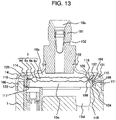
- the difference between the fourth example not covered by the claimed invention and the first example not covered by the claimed invention is that the recess end surface 115 of the pump housing 1 and a lower end portion 124 of the upper holding member 104 are in contact with each other, contrary to the invention, but the pump housing 1 and the lower holding member 105 are not in contact with each other.
- the parts except for this are the same as those in the first example not covered by the claimed invention, and the described codes and numerals are all common to the first example not covered by the claimed invention.
- Fig. 13 is a vertical sectional view of a high pressure fuel supply pump in the present example not covered by the claimed invention, and is an enlarged view of the metal diaphragm damper 9 portion for absorbing pressure pulsation.
- the damper cover 14 and the upper holding member 104 are in contact with each other at the contact portion 114. Meanwhile, the recess end surface 115 of the pump housing 1 and the lower end portion 124 of the upper holding member 104 are in contact with each other, contrary to the invention.
- the metal diaphragm damper 9 is vertically sandwiched by only mutual press-fitting force of the upper holding member 104 and the lower holding member 105.
- the relief valve housing 206 slips upward in the drawing by the high pressure fuel due to a certain error, the relief valve housing 206 and the upper holding member 104 contact each other at first, where the relief valve housing 206 is prevented from slipping off.
Landscapes
- Engineering & Computer Science (AREA)
- Mechanical Engineering (AREA)
- General Engineering & Computer Science (AREA)
- Chemical & Material Sciences (AREA)
- Combustion & Propulsion (AREA)
- Fuel-Injection Apparatus (AREA)
- Pipe Accessories (AREA)
- Chemical Kinetics & Catalysis (AREA)
- General Chemical & Material Sciences (AREA)
- Oil, Petroleum & Natural Gas (AREA)
Claims (8)
- Hochdruckkraftstoffpumpe, die Folgendes umfasst:ein Pumpengehäuse (1),eine Druckkammer (11), die im Pumpengehäuse (1) vorgesehen ist,eine Dämpferkammer (10b, 10c), die durch das Pumpengehäuse (1) und eine Dämpferabdeckung (14) gebildet ist,einen Metallmembrandämpfer (9), der in der Dämpferkammer (10b, 10c) angeordnet ist, undein Paar eines oberen Halteelements (104) und eines unteren Halteelements (105), das den Metallmembrandämpfer (9) vertikal einklemmt, wobeidas obere Halteelement (104) mit der Dämpferabdeckung (14) in Kontakt ist und das untere Halteelement (105) mit dem Pumpengehäuse (1) in Kontakt ist,eine Aussparungsstirnfläche (115) des Pumpengehäuses (1) und das untere Halteelement (105) miteinander in Kontakt sind undder Schweißabschnitt (106) die Dämpferabdeckung (14) bei einem gesamten Umfang des Einpressabschnitts (122) am Pumpengehäuse (1) befestigt, derart, dass sie durch Anwenden von Schweißen am gesamten Umfang in einem Schweißabschnitt (106) flüssigkeitsdicht befestigt ist; gekennzeichnet durcheinen Einpressabschnitt (122) des Pumpengehäuses (1), bei dem eine ringförmige Oberfläche der Dämpferabdeckung (14) in eine ringförmige Oberfläche des Pumpengehäuses (1) vorübergehend eingepresst ist, wobeizu diesem Zeitpunkt bereits ein vorstehender Abschnitt (120) der Dämpferabdeckung (14) und das obere Halteelement (104) im Kontaktabschnitt (114) miteinander in Kontakt sind undder Schweißabschnitt (106) die Dämpferabdeckung (14) bei einem gesamten Umfang des Einpressabschnitts (122) zum Pumpengehäuse (1) durchdringt.
- Hochdruckkraftstoffpumpe nach Anspruch 1, wobei die Dämpferabdeckung (14) in einer Becherform gebildet ist und die ringförmige Oberfläche eine zylindrische Außenoberfläche der Dämpferabdeckung (14) ist, die auf einer offenen Seite der Dämpferabdeckung (14) gebildet ist.
- Hochdruckkraftstoffpumpe nach Anspruch 1, wobei die Dämpferabdeckung (14) aus einem gewalzten Stahlsitz durch Pressen hergestellt ist.
- Hochdruckkraftstoffpumpe nach Anspruch 1, die ferner Folgendes umfasst:
einen ringförmigen Raum (121) zwischen der Dämpferabdeckung (14) und dem oberen Halteelement (104). - Hochdruckkraftstoffpumpe nach Anspruch 1, die ferner Folgendes umfasst:einen Kolben (2), der konfiguriert ist, eine Wechselbewegung durchzuführen, die in die Druckkammer (11) ansteigt und aus der Druckkammer (11) absinkt,einen Zylinder (6) zum Führen der Wechselbewegung des Kolbens (2),eine Kolbendichtung (13), die mit einem Außenumfang des Kolbens (2) gleitend in Kontakt ist,eine Dichtungskammer (10f), die zwischen dem Endabschnitt des Zylinders (6) und der Kolbendichtung (13) gebildet ist, undeinen Einlassdurchgang (10d), der die Dämpferkammer (10b, 10c) mit der Dichtungskammer (10f) verbindet, wobeider Einlassdurchgang (10d) vom unteren Halteelement (105) radial einwärts angeordnet ist.
- Hochdruckkraftstoffpumpe nach Anspruch 1, die ferner Folgendes umfasst:einen Einlassdurchgang (10c), der die Dämpferkammer (10b) mit einem Einlassanschluss (30a) eines elektromagnetischen Einlassventilmechanismus (30) verbindet, wobeider Einlassdurchgang (10c) vom unteren Halteelement (105) radial einwärts angeordnet ist.
- Hochdruckkraftstoffpumpe nach Anspruch 1, wobei
die Dämpferabdeckung (14) in einer Becherform gebildet ist und einen Bodenabschnitt und einen Öffnungsabschnitt enthält, wobei der Bodenabschnitt nach oben gerichtet angeordnet ist und der Öffnungsabschnitt nach unten gerichtet angeordnet ist. - Verfahren zum Herstellen einer Hochdruckkraftstoffpumpe, die Folgendes umfasst:ein Pumpengehäuse (1),eine Druckkammer (11), die im Pumpengehäuse (1) vorgesehen ist,eine Dämpferkammer (10b, 10c), die durch das Pumpengehäuse (1) und eine Dämpferabdeckung (14) gebildet ist,einen Metallmembrandämpfer (9), der in der Dämpferkammer (10b, 10c) angeordnet ist,ein Paar eines oberen Halteelements (104) und eines unteren Halteelements (105), das den Metallmembrandämpfer (9) vertikal einklemmt, wobei das obere Halteelement (104) mit der Dämpferabdeckung (14) in Kontakt ist und das untere Halteelement (105) mit dem Pumpengehäuse (1) in Kontakt ist; undeinen Einpressabschnitt (122) des Pumpengehäuses (1), bei dem eine ringförmige Oberfläche der Dämpferabdeckung (14) in eine ringförmige Oberfläche des Pumpengehäuses (1) vorübergehend eingepresst ist, wobeizu diesem Zeitpunkt bereits ein vorstehender Abschnitt (120) der Dämpferabdeckung (14) und das obere Halteelement (104) im Kontaktabschnitt (114) miteinander in Kontakt sind und die Aussparungsstirnfläche (115) des Pumpengehäuses (1) und des unteren Halteelements (105) miteinander in Kontakt sind,der Schweißabschnitt (106) die Dämpferabdeckung (14) bei einem gesamten Umfang des Einpressabschnitts (122) am Pumpengehäuse (1) befestigt, derart, dass sie durch Anwenden von Schweißen am gesamten Umfang in einem Schweißabschnitt (106) flüssigkeitsdicht befestigt ist; undder Schweißabschnitt (106) die Dämpferabdeckung (14) bei einem gesamten Umfang des Einpressabschnitts (122) zum Pumpengehäuse (1) durchdringt.
Applications Claiming Priority (3)
| Application Number | Priority Date | Filing Date | Title |
|---|---|---|---|
| JP2008114758A JP5002523B2 (ja) | 2008-04-25 | 2008-04-25 | 燃料の圧力脈動低減機構、及びそれを備えた内燃機関の高圧燃料供給ポンプ |
| EP14175110.7A EP2803851B1 (de) | 2008-04-25 | 2009-04-23 | Hochdruckbrennstoffpumpe eines verbrennungsmotors |
| EP09158668.5A EP2112368B1 (de) | 2008-04-25 | 2009-04-23 | Mechanismus zur Verzögerung der Kraftstoffdruckpulsation und Hochdruck-Kraftstoffpumpe mit solch einem Mechanismus |
Related Parent Applications (3)
| Application Number | Title | Priority Date | Filing Date |
|---|---|---|---|
| EP09158668.5A Division EP2112368B1 (de) | 2008-04-25 | 2009-04-23 | Mechanismus zur Verzögerung der Kraftstoffdruckpulsation und Hochdruck-Kraftstoffpumpe mit solch einem Mechanismus |
| EP14175110.7A Division EP2803851B1 (de) | 2008-04-25 | 2009-04-23 | Hochdruckbrennstoffpumpe eines verbrennungsmotors |
| EP14175110.7A Division-Into EP2803851B1 (de) | 2008-04-25 | 2009-04-23 | Hochdruckbrennstoffpumpe eines verbrennungsmotors |
Publications (2)
| Publication Number | Publication Date |
|---|---|
| EP3444469A1 EP3444469A1 (de) | 2019-02-20 |
| EP3444469B1 true EP3444469B1 (de) | 2022-08-17 |
Family
ID=40957857
Family Applications (4)
| Application Number | Title | Priority Date | Filing Date |
|---|---|---|---|
| EP14175110.7A Active EP2803851B1 (de) | 2008-04-25 | 2009-04-23 | Hochdruckbrennstoffpumpe eines verbrennungsmotors |
| EP18191492.0A Active EP3444469B1 (de) | 2008-04-25 | 2009-04-23 | Mechanismus zur einschränkung der kraftstoffdruckpulsation und hochdruckbrennstoffpumpe eines verbrennungsmotors mit solch einem mechanismus |
| EP09158668.5A Active EP2112368B1 (de) | 2008-04-25 | 2009-04-23 | Mechanismus zur Verzögerung der Kraftstoffdruckpulsation und Hochdruck-Kraftstoffpumpe mit solch einem Mechanismus |
| EP12159845A Ceased EP2466114A1 (de) | 2008-04-25 | 2009-04-23 | Hochdruck-Kraftstoffpumpe mit einem Mechanismus zur Verzögerung der Kraftstoffdruckpulsation |
Family Applications Before (1)
| Application Number | Title | Priority Date | Filing Date |
|---|---|---|---|
| EP14175110.7A Active EP2803851B1 (de) | 2008-04-25 | 2009-04-23 | Hochdruckbrennstoffpumpe eines verbrennungsmotors |
Family Applications After (2)
| Application Number | Title | Priority Date | Filing Date |
|---|---|---|---|
| EP09158668.5A Active EP2112368B1 (de) | 2008-04-25 | 2009-04-23 | Mechanismus zur Verzögerung der Kraftstoffdruckpulsation und Hochdruck-Kraftstoffpumpe mit solch einem Mechanismus |
| EP12159845A Ceased EP2466114A1 (de) | 2008-04-25 | 2009-04-23 | Hochdruck-Kraftstoffpumpe mit einem Mechanismus zur Verzögerung der Kraftstoffdruckpulsation |
Country Status (3)
| Country | Link |
|---|---|
| US (5) | US8393881B2 (de) |
| EP (4) | EP2803851B1 (de) |
| JP (1) | JP5002523B2 (de) |
Families Citing this family (78)
| Publication number | Priority date | Publication date | Assignee | Title |
|---|---|---|---|---|
| DE102008047303A1 (de) * | 2008-02-18 | 2009-08-20 | Continental Teves Ag & Co. Ohg | Pulsationsdämpfungskapsel |
| JP4825842B2 (ja) * | 2008-06-09 | 2011-11-30 | トヨタ自動車株式会社 | 燃料ポンプ |
| MX2011003624A (es) | 2008-10-22 | 2012-01-27 | Graco Minnesota Inc | Rociador sin aire portatil. |
| JP5478051B2 (ja) * | 2008-10-30 | 2014-04-23 | 日立オートモティブシステムズ株式会社 | 高圧燃料供給ポンプ |
| JP4736142B2 (ja) * | 2009-02-18 | 2011-07-27 | 株式会社デンソー | 高圧ポンプ |
| DE102009014072B4 (de) * | 2009-03-20 | 2014-09-25 | Continental Automotive Gmbh | Common-Rail-Einspritzsystem sowie Verfahren zur Druckentlastung eines Common-Rail-Einspritzsystems |
| JP5372692B2 (ja) * | 2009-10-06 | 2013-12-18 | 日立オートモティブシステムズ株式会社 | 高圧燃料ポンプ |
| JP5231380B2 (ja) * | 2009-11-09 | 2013-07-10 | 株式会社デンソー | ダンパアセンブリ、それを用いた高圧ポンプ及び高圧ポンプの製造方法 |
| JP5408010B2 (ja) * | 2010-04-08 | 2014-02-05 | 株式会社デンソー | 高圧ポンプ |
| DE102010028036A1 (de) * | 2010-04-21 | 2011-10-27 | Robert Bosch Gmbh | Hochdruckpumpe |
| JP5382548B2 (ja) * | 2011-03-31 | 2014-01-08 | 株式会社デンソー | 高圧ポンプ |
| JP5382551B2 (ja) | 2011-03-31 | 2014-01-08 | 株式会社デンソー | 高圧ポンプ |
| US9109593B2 (en) | 2011-08-23 | 2015-08-18 | Denso Corporation | High pressure pump |
| JP5664604B2 (ja) * | 2011-08-23 | 2015-02-04 | 株式会社デンソー | 高圧ポンプ |
| JP2013079618A (ja) * | 2011-10-05 | 2013-05-02 | Hitachi Automotive Systems Ltd | 高圧燃料供給ポンプ |
| CA2754183C (en) | 2011-10-05 | 2013-01-08 | Westport Power Inc. | Module for managing mass flow and dampening pressure pulsations in a gaseous fuel supply line |
| DE102011090186A1 (de) * | 2011-12-30 | 2013-07-04 | Continental Automotive Gmbh | Niederdruckdämpfer für Kraftstoffpumpen |
| JP2012149652A (ja) * | 2012-05-16 | 2012-08-09 | Hitachi Automotive Systems Ltd | 燃料の圧力脈動低減機構、及びそれを備えた内燃機関の高圧燃料供給ポンプ |
| DE102012212745A1 (de) * | 2012-07-19 | 2014-01-23 | Fmp Technology Gmbh Fluid Measurements & Projects | Kraftstoffeinspritzsystem |
| DE102013206930A1 (de) * | 2013-04-17 | 2014-10-23 | Robert Bosch Gmbh | Kolbenpumpe, insbesondere Kraftstoff-Hochdruckpumpe |
| JP6221410B2 (ja) * | 2013-06-27 | 2017-11-01 | トヨタ自動車株式会社 | 高圧燃料ポンプ |
| DE102013212565A1 (de) * | 2013-06-28 | 2014-12-31 | Robert Bosch Gmbh | Kraftstoffhochdruckpumpe |
| JP6219672B2 (ja) * | 2013-10-28 | 2017-10-25 | 日立オートモティブシステムズ株式会社 | 高圧燃料供給ポンプ |
| PL3102828T3 (pl) | 2014-02-07 | 2020-02-28 | Graco Minnesota Inc. | Układ napędowy do bezpulsacyjnej pompy wyporowej |
| GB201402528D0 (en) * | 2014-02-13 | 2014-04-02 | Delphi Int Operations Luxembourg Sarl | High pressure fuel pump |
| EP2924330B1 (de) * | 2014-03-27 | 2018-01-31 | Sonplas GmbH | Vorrichtung und Verfahren zum Schutz vor Fluidpulsationen |
| JP6470267B2 (ja) * | 2014-04-25 | 2019-02-13 | 日立オートモティブシステムズ株式会社 | 高圧燃料供給ポンプ |
| JP2015218678A (ja) * | 2014-05-20 | 2015-12-07 | 日立オートモティブシステムズ株式会社 | リリーフ弁を備えた高圧燃料供給ポンプ |
| US9932949B2 (en) * | 2014-11-07 | 2018-04-03 | Denso Corporation | High pressure pump |
| JP6387812B2 (ja) * | 2014-12-05 | 2018-09-12 | 株式会社デンソー | 高圧ポンプ、及び、それを用いる燃料供給システム |
| US10041435B2 (en) | 2014-12-16 | 2018-08-07 | Fca Us Llc | Direct injection fuel system with controlled accumulator energy storage and delivery |
| JP6012785B2 (ja) * | 2015-01-30 | 2016-10-25 | 日立オートモティブシステムズ株式会社 | 燃料の圧力脈動低減機構、及びそれを備えた内燃機関の高圧燃料供給ポンプ |
| JP6534832B2 (ja) * | 2015-03-06 | 2019-06-26 | 株式会社ケーヒン | 燃料供給装置及びベローズ式ダンパ |
| JP6317701B2 (ja) * | 2015-04-10 | 2018-04-25 | 株式会社デンソー | 高圧ポンプ |
| JP6434871B2 (ja) * | 2015-07-31 | 2018-12-05 | トヨタ自動車株式会社 | ダンパ装置 |
| DE102015214812B4 (de) * | 2015-08-04 | 2020-01-23 | Continental Automotive Gmbh | Kraftstoffhochdruckpumpe |
| US10408201B2 (en) * | 2015-09-01 | 2019-09-10 | PSC Engineering, LLC | Positive displacement pump |
| JP6513818B2 (ja) | 2015-09-29 | 2019-05-15 | 日立オートモティブシステムズ株式会社 | 高圧燃料ポンプ |
| DE102015219415B4 (de) * | 2015-10-07 | 2020-07-09 | Vitesco Technologies GmbH | Kraftstoffhochdruckpumpe sowie Kraftstoffversorgungseinrichtung für eine Verbrennungskraftmaschine, insbesondere eines Kraftwagens |
| DE102015219419B3 (de) | 2015-10-07 | 2017-02-23 | Continental Automotive Gmbh | Pumpeinrichtung sowie Kraftstoffversorgungseinrichtung für eine Verbrennungskraftmaschine und Mischeinrichtung, insbesondere für einen Kraftwagen |
| DE102015219537A1 (de) * | 2015-10-08 | 2017-04-27 | Robert Bosch Gmbh | Membrandose zum Dämpfen von Druckpulsationen in einem Niederdruckbereich einer Kolbenpumpe |
| DE102016206459B3 (de) * | 2016-04-18 | 2017-10-05 | Continental Automotive Gmbh | Kombination, umfassend ein Gehäuse und einen Flansch, und Anordnung |
| DE102016212469A1 (de) * | 2016-07-08 | 2018-01-11 | Robert Bosch Gmbh | Verfahren zur Herstellung einer Kraftstoffhochdruckpumpe |
| DE102016217409A1 (de) * | 2016-09-13 | 2018-03-15 | Robert Bosch Gmbh | Kraftstoff-Hochdruckpumpe |
| US11007545B2 (en) | 2017-01-15 | 2021-05-18 | Graco Minnesota Inc. | Handheld airless paint sprayer repair |
| CN106762273B (zh) * | 2017-03-21 | 2022-05-20 | 北油电控燃油喷射系统(天津)有限公司 | 一种机油润滑的高压燃油泵 |
| JP6397961B2 (ja) * | 2017-05-22 | 2018-09-26 | 日立オートモティブシステムズ株式会社 | 高圧燃料供給ポンプ |
| JP2019015244A (ja) * | 2017-07-07 | 2019-01-31 | 株式会社ケーヒン | 燃料ポンプ |
| KR101986017B1 (ko) * | 2017-09-20 | 2019-09-03 | 주식회사 현대케피코 | 고압연료펌프 |
| DE102017217363A1 (de) * | 2017-09-29 | 2019-04-04 | Continental Automotive Gmbh | Kraftstoffeinspritzsystem mit Filtration des Kraftstoffs |
| US11047353B2 (en) | 2017-12-05 | 2021-06-29 | Hitachi Automotive Systems, Ltd. | High-pressure fuel supply pump |
| GB2569793B (en) * | 2017-12-21 | 2020-04-22 | Delphi Automotive Systems Lux | High pressure fuel pump |
| DE102018200083A1 (de) * | 2018-01-04 | 2019-07-04 | Continental Automotive Gmbh | Kraftstoffhochdruckpumpe |
| US11022106B2 (en) | 2018-01-09 | 2021-06-01 | Graco Minnesota Inc. | High-pressure positive displacement plunger pump |
| DE102018204556B3 (de) * | 2018-03-26 | 2019-05-16 | Continental Automotive Gmbh | Kraftstoffhochdruckpumpe für ein Kraftstoffeinspritzsystem |
| CN112368082B (zh) | 2018-04-10 | 2022-11-08 | 固瑞克明尼苏达有限公司 | 用于油漆和其他涂料的手持式无气喷涂器 |
| JP7237952B2 (ja) | 2018-05-18 | 2023-03-13 | イーグル工業株式会社 | ダンパユニット |
| WO2019221259A1 (ja) | 2018-05-18 | 2019-11-21 | イーグル工業株式会社 | メタルダイアフラムダンパの取付構造 |
| WO2019221260A1 (ja) | 2018-05-18 | 2019-11-21 | イーグル工業株式会社 | ダンパ装置 |
| JP7074563B2 (ja) | 2018-05-18 | 2022-05-24 | イーグル工業株式会社 | ダンパ装置 |
| CN112055780A (zh) * | 2018-05-25 | 2020-12-08 | 伊格尔工业股份有限公司 | 减震器装置 |
| JP6681448B2 (ja) * | 2018-08-31 | 2020-04-15 | 日立オートモティブシステムズ株式会社 | 高圧燃料供給ポンプ |
| DE112019004421T5 (de) | 2018-10-01 | 2021-06-24 | Hitachi Astemo, Ltd. | Hochdruck-kraftstoffpumpe |
| DE102018217990A1 (de) * | 2018-10-22 | 2020-04-23 | Robert Bosch Gmbh | Hochdruckpumpenanordnung |
| US11499515B2 (en) * | 2019-02-08 | 2022-11-15 | Delphi Technologies Ip Limited | Fuel pump and inlet valve assembly thereof |
| CN115739435A (zh) | 2019-05-31 | 2023-03-07 | 固瑞克明尼苏达有限公司 | 手持式流体喷雾器 |
| DE102019212005A1 (de) * | 2019-08-09 | 2021-02-11 | Robert Bosch Gmbh | Kraftstoff-Hochdruckpumpe |
| US10969049B1 (en) | 2019-09-27 | 2021-04-06 | Robert Bosch Gmbh | Fluid damper |
| JP2021110312A (ja) * | 2020-01-15 | 2021-08-02 | 株式会社デンソー | アッセンブリの製造方法、パーツセット、燃料噴射ポンプの製造方法、及び、燃料噴射ポンプ |
| DE102020104313B3 (de) * | 2020-02-19 | 2021-01-28 | Schaeffler Technologies AG & Co. KG | Stößel zur Beaufschlagung eines Pumpenkolbens einer Kraftstoffhochdruckpumpe |
| US12366233B2 (en) | 2020-03-31 | 2025-07-22 | Graco Minnesota Inc. | Electrically operated pump for a plural component spray system |
| US12565877B2 (en) | 2020-03-31 | 2026-03-03 | Graco Minnesota Inc. | Electrically operated linear pump and pump drive |
| CN115362316A (zh) | 2020-03-31 | 2022-11-18 | 固瑞克明尼苏达有限公司 | 电动操作的往复式泵 |
| US10968903B1 (en) | 2020-06-04 | 2021-04-06 | Graco Minnesota Inc. | Handheld sanitary fluid sprayer having resilient polymer pump cylinder |
| US10926275B1 (en) | 2020-06-25 | 2021-02-23 | Graco Minnesota Inc. | Electrostatic handheld sprayer |
| US12006901B2 (en) * | 2020-07-17 | 2024-06-11 | Hitachi Astemo, Ltd. | Fuel pump |
| US11644140B2 (en) * | 2020-08-16 | 2023-05-09 | Piranha Plastics, Llc | Flow dampener in flow measurement system |
| US11484900B2 (en) | 2021-01-07 | 2022-11-01 | S. C. Johnson & Son, Inc. | Dispenser |
Family Cites Families (31)
| Publication number | Priority date | Publication date | Assignee | Title |
|---|---|---|---|---|
| DE3134859A1 (de) * | 1981-09-03 | 1983-07-07 | Robert Bosch Gmbh, 7000 Stuttgart | Gasgefuelltes element zum daempfen von druckpulsationen |
| EP0115501A4 (de) | 1982-08-09 | 1985-02-28 | Rast Pty Ltd W | Verfahren und mechanismus zur druckstossdämpfung. |
| DE3432727A1 (de) | 1984-05-10 | 1985-11-14 | Robert Bosch Gmbh, 7000 Stuttgart | Kraftstoffversorgungsleitung |
| US4649884A (en) * | 1986-03-05 | 1987-03-17 | Walbro Corporation | Fuel rail for internal combustion engines |
| DE19531811A1 (de) | 1995-08-30 | 1997-03-06 | Bosch Gmbh Robert | Kraftstoffeinspritzpumpe |
| US5617827A (en) | 1995-12-26 | 1997-04-08 | General Motors Corporation | Fuel rail |
| DE19705405A1 (de) | 1997-02-13 | 1998-08-20 | Bosch Gmbh Robert | Vorrichtung für eine Kraftstoffanlage |
| TW384358B (en) | 1997-09-25 | 2000-03-11 | Mitsubishi Electric Corp | High pressure fuel supply pump body for an in-cylinder fuel injection engine |
| JPH11132130A (ja) | 1997-10-27 | 1999-05-18 | Mitsubishi Electric Corp | 筒内噴射用高圧燃料ポンプ |
| DE10016880A1 (de) | 2000-04-05 | 2001-10-18 | Bayerische Motoren Werke Ag | Schwingungsdämpfer für eine hydraulische Fahrzeug-Bremsanlage |
| US6901964B2 (en) * | 2001-03-30 | 2005-06-07 | Saturn Electronics & Engineering, Inc. | Vehicle fuel pulse damper |
| JP2003247474A (ja) | 2002-02-20 | 2003-09-05 | Bosch Automotive Systems Corp | 高圧燃料ポンプ |
| JP3823060B2 (ja) | 2002-03-04 | 2006-09-20 | 株式会社日立製作所 | 高圧燃料供給ポンプ |
| JP3944413B2 (ja) * | 2002-05-24 | 2007-07-11 | 株式会社日立製作所 | 高圧燃料供給ポンプ |
| EP1411236B1 (de) * | 2002-10-19 | 2012-10-10 | Robert Bosch Gmbh | Vorrichtung zum Dämpfen von Druckpulsationen in einem Fluidsystem, insbesondere in einem Kraftstoffsystem einer Brennkraftmaschine |
| DE10311855B4 (de) * | 2003-03-17 | 2005-04-28 | Infineon Technologies Ag | Anordnung zum Übertragen von Informationen/Strukturen auf Wafer unter Verwendung eines Stempels |
| US20040202562A1 (en) * | 2003-04-14 | 2004-10-14 | Grassbaugh Walter T. | Reciprocating compressor |
| JP4036153B2 (ja) * | 2003-07-22 | 2008-01-23 | 株式会社日立製作所 | ダンパ機構及び高圧燃料供給ポンプ |
| DE10345725B4 (de) * | 2003-10-01 | 2017-01-05 | Robert Bosch Gmbh | Kraftstoff-Hochdruckpumpe |
| DE102004047601A1 (de) * | 2004-08-13 | 2006-02-23 | Robert Bosch Gmbh | Fluidpumpe, insbesondere Kraftstoff-Hochdruckpumpe |
| DE102004063075B4 (de) * | 2004-12-28 | 2015-11-26 | Robert Bosch Gmbh | Kraftstoff-Hochdruckpumpe für eine Brennkraftmaschine mit einem Stufenkolben und einem Mengensteuerventil |
| DE102004063074B4 (de) * | 2004-12-28 | 2013-03-07 | Robert Bosch Gmbh | Kolbenpumpe, insbesondere Kraftstoff-Hochdruckpumpe für eine Brennkraftmaschine |
| JP4215000B2 (ja) * | 2005-01-19 | 2009-01-28 | 株式会社デンソー | 高圧ポンプ |
| US7335853B2 (en) * | 2005-03-25 | 2008-02-26 | Mcgushion Kevin | Method for orbital welding using a pulsed current |
| JP4453028B2 (ja) * | 2005-03-30 | 2010-04-21 | 株式会社デンソー | 高圧燃料ポンプ |
| EP1731761B1 (de) * | 2005-06-09 | 2007-07-11 | THOMAS MAGNETE GmbH | Dosierpumpe |
| JP4648254B2 (ja) * | 2006-06-22 | 2011-03-09 | 日立オートモティブシステムズ株式会社 | 高圧燃料ポンプ |
| JP4487265B2 (ja) | 2006-07-11 | 2010-06-23 | 株式会社デンソー | 高圧燃料ポンプ |
| JP2008057451A (ja) | 2006-08-31 | 2008-03-13 | Hitachi Ltd | 高圧燃料供給ポンプ |
| JP4686501B2 (ja) * | 2007-05-21 | 2011-05-25 | 日立オートモティブシステムズ株式会社 | 液体脈動ダンパ機構、および液体脈動ダンパ機構を備えた高圧燃料供給ポンプ |
| JP4380751B2 (ja) * | 2007-09-11 | 2009-12-09 | 株式会社日立製作所 | ダンパ機構及び高圧燃料供給ポンプ |
-
2008
- 2008-04-25 JP JP2008114758A patent/JP5002523B2/ja active Active
-
2009
- 2009-04-23 EP EP14175110.7A patent/EP2803851B1/de active Active
- 2009-04-23 US US12/428,967 patent/US8393881B2/en active Active
- 2009-04-23 EP EP18191492.0A patent/EP3444469B1/de active Active
- 2009-04-23 EP EP09158668.5A patent/EP2112368B1/de active Active
- 2009-04-23 EP EP12159845A patent/EP2466114A1/de not_active Ceased
-
2013
- 2013-01-31 US US13/754,932 patent/US8876502B2/en active Active
-
2014
- 2014-09-26 US US14/497,755 patent/US9709055B2/en active Active
-
2017
- 2017-06-08 US US15/617,766 patent/US10107285B2/en active Active
-
2018
- 2018-09-10 US US16/126,774 patent/US11047380B2/en active Active
Also Published As
| Publication number | Publication date |
|---|---|
| US20170276130A1 (en) | 2017-09-28 |
| EP2112368A3 (de) | 2009-11-11 |
| US8393881B2 (en) | 2013-03-12 |
| US8876502B2 (en) | 2014-11-04 |
| US20130149177A1 (en) | 2013-06-13 |
| US20150017041A1 (en) | 2015-01-15 |
| US10107285B2 (en) | 2018-10-23 |
| US11047380B2 (en) | 2021-06-29 |
| EP2803851B1 (de) | 2018-10-10 |
| US20190003475A1 (en) | 2019-01-03 |
| US20090288639A1 (en) | 2009-11-26 |
| JP2009264239A (ja) | 2009-11-12 |
| EP2112368A2 (de) | 2009-10-28 |
| EP2803851A1 (de) | 2014-11-19 |
| EP3444469A1 (de) | 2019-02-20 |
| EP2112368B1 (de) | 2014-11-19 |
| EP2466114A1 (de) | 2012-06-20 |
| US9709055B2 (en) | 2017-07-18 |
| JP5002523B2 (ja) | 2012-08-15 |
Similar Documents
| Publication | Publication Date | Title |
|---|---|---|
| EP3444469B1 (de) | Mechanismus zur einschränkung der kraftstoffdruckpulsation und hochdruckbrennstoffpumpe eines verbrennungsmotors mit solch einem mechanismus | |
| EP3358177B1 (de) | Hochdruckbrennstoffpumpe | |
| EP3587790B1 (de) | Hochdruckbrennstoffförderpumpe | |
| EP3467297A1 (de) | Hochdruckkraftstoffförderpumpe | |
| EP3543519B1 (de) | Hochdruckbrennstoffförderpumpe | |
| CN115398090A (zh) | 高压燃料供给泵和制造方法 | |
| JP6310026B2 (ja) | 燃料の圧力脈動低減機構、及びそれを備えた内燃機関の高圧燃料供給ポンプ | |
| US12006901B2 (en) | Fuel pump | |
| CN110832188B (zh) | 高压燃料泵 | |
| EP3135899B1 (de) | Hochdruckbrennstoffpumpe | |
| JP7139265B2 (ja) | 高圧燃料供給ポンプ及びリリーフ弁機構 | |
| JP7482313B2 (ja) | 燃料ポンプ | |
| US12140113B2 (en) | Electromagnetic valve mechanism and fuel pump | |
| JP6511559B2 (ja) | 燃料の圧力脈動低減機構、及びそれを備えた内燃機関の高圧燃料供給ポンプ | |
| JP7644684B2 (ja) | 燃料ポンプ | |
| JP7385750B2 (ja) | 燃料ポンプ | |
| JP2017072027A (ja) | 高圧燃料供給ポンプ | |
| JP2021148043A (ja) | 燃料ポンプ |
Legal Events
| Date | Code | Title | Description |
|---|---|---|---|
| PUAI | Public reference made under article 153(3) epc to a published international application that has entered the european phase |
Free format text: ORIGINAL CODE: 0009012 |
|
| STAA | Information on the status of an ep patent application or granted ep patent |
Free format text: STATUS: REQUEST FOR EXAMINATION WAS MADE |
|
| 17P | Request for examination filed |
Effective date: 20180927 |
|
| AC | Divisional application: reference to earlier application |
Ref document number: 2112368 Country of ref document: EP Kind code of ref document: P Ref document number: 2803851 Country of ref document: EP Kind code of ref document: P |
|
| AK | Designated contracting states |
Kind code of ref document: A1 Designated state(s): AT BE BG CH CY CZ DE DK EE ES FI FR GB GR HR HU IE IS IT LI LT LU LV MC MK MT NL NO PL PT RO SE SI SK TR |
|
| STAA | Information on the status of an ep patent application or granted ep patent |
Free format text: STATUS: EXAMINATION IS IN PROGRESS |
|
| 17Q | First examination report despatched |
Effective date: 20190919 |
|
| RAP1 | Party data changed (applicant data changed or rights of an application transferred) |
Owner name: HITACHI ASTEMO, LTD. |
|
| GRAP | Despatch of communication of intention to grant a patent |
Free format text: ORIGINAL CODE: EPIDOSNIGR1 |
|
| STAA | Information on the status of an ep patent application or granted ep patent |
Free format text: STATUS: GRANT OF PATENT IS INTENDED |
|
| INTG | Intention to grant announced |
Effective date: 20220506 |
|
| GRAS | Grant fee paid |
Free format text: ORIGINAL CODE: EPIDOSNIGR3 |
|
| GRAA | (expected) grant |
Free format text: ORIGINAL CODE: 0009210 |
|
| STAA | Information on the status of an ep patent application or granted ep patent |
Free format text: STATUS: THE PATENT HAS BEEN GRANTED |
|
| AC | Divisional application: reference to earlier application |
Ref document number: 2112368 Country of ref document: EP Kind code of ref document: P Ref document number: 2803851 Country of ref document: EP Kind code of ref document: P |
|
| AK | Designated contracting states |
Kind code of ref document: B1 Designated state(s): AT BE BG CH CY CZ DE DK EE ES FI FR GB GR HR HU IE IS IT LI LT LU LV MC MK MT NL NO PL PT RO SE SI SK TR |
|
| REG | Reference to a national code |
Ref country code: CH Ref legal event code: EP |
|
| REG | Reference to a national code |
Ref country code: DE Ref legal event code: R096 Ref document number: 602009064566 Country of ref document: DE |
|
| REG | Reference to a national code |
Ref country code: IE Ref legal event code: FG4D |
|
| REG | Reference to a national code |
Ref country code: AT Ref legal event code: REF Ref document number: 1512349 Country of ref document: AT Kind code of ref document: T Effective date: 20220915 |
|
| REG | Reference to a national code |
Ref country code: NL Ref legal event code: MP Effective date: 20220817 |
|
| REG | Reference to a national code |
Ref country code: LT Ref legal event code: MG9D |
|
| PG25 | Lapsed in a contracting state [announced via postgrant information from national office to epo] |
Ref country code: SE Free format text: LAPSE BECAUSE OF FAILURE TO SUBMIT A TRANSLATION OF THE DESCRIPTION OR TO PAY THE FEE WITHIN THE PRESCRIBED TIME-LIMIT Effective date: 20220817 Ref country code: PT Free format text: LAPSE BECAUSE OF FAILURE TO SUBMIT A TRANSLATION OF THE DESCRIPTION OR TO PAY THE FEE WITHIN THE PRESCRIBED TIME-LIMIT Effective date: 20221219 Ref country code: NO Free format text: LAPSE BECAUSE OF FAILURE TO SUBMIT A TRANSLATION OF THE DESCRIPTION OR TO PAY THE FEE WITHIN THE PRESCRIBED TIME-LIMIT Effective date: 20221117 Ref country code: NL Free format text: LAPSE BECAUSE OF FAILURE TO SUBMIT A TRANSLATION OF THE DESCRIPTION OR TO PAY THE FEE WITHIN THE PRESCRIBED TIME-LIMIT Effective date: 20220817 Ref country code: LV Free format text: LAPSE BECAUSE OF FAILURE TO SUBMIT A TRANSLATION OF THE DESCRIPTION OR TO PAY THE FEE WITHIN THE PRESCRIBED TIME-LIMIT Effective date: 20220817 Ref country code: LT Free format text: LAPSE BECAUSE OF FAILURE TO SUBMIT A TRANSLATION OF THE DESCRIPTION OR TO PAY THE FEE WITHIN THE PRESCRIBED TIME-LIMIT Effective date: 20220817 Ref country code: FI Free format text: LAPSE BECAUSE OF FAILURE TO SUBMIT A TRANSLATION OF THE DESCRIPTION OR TO PAY THE FEE WITHIN THE PRESCRIBED TIME-LIMIT Effective date: 20220817 |
|
| REG | Reference to a national code |
Ref country code: AT Ref legal event code: MK05 Ref document number: 1512349 Country of ref document: AT Kind code of ref document: T Effective date: 20220817 |
|
| PG25 | Lapsed in a contracting state [announced via postgrant information from national office to epo] |
Ref country code: PL Free format text: LAPSE BECAUSE OF FAILURE TO SUBMIT A TRANSLATION OF THE DESCRIPTION OR TO PAY THE FEE WITHIN THE PRESCRIBED TIME-LIMIT Effective date: 20220817 Ref country code: IS Free format text: LAPSE BECAUSE OF FAILURE TO SUBMIT A TRANSLATION OF THE DESCRIPTION OR TO PAY THE FEE WITHIN THE PRESCRIBED TIME-LIMIT Effective date: 20221217 Ref country code: HR Free format text: LAPSE BECAUSE OF FAILURE TO SUBMIT A TRANSLATION OF THE DESCRIPTION OR TO PAY THE FEE WITHIN THE PRESCRIBED TIME-LIMIT Effective date: 20220817 Ref country code: GR Free format text: LAPSE BECAUSE OF FAILURE TO SUBMIT A TRANSLATION OF THE DESCRIPTION OR TO PAY THE FEE WITHIN THE PRESCRIBED TIME-LIMIT Effective date: 20221118 |
|
| PG25 | Lapsed in a contracting state [announced via postgrant information from national office to epo] |
Ref country code: RO Free format text: LAPSE BECAUSE OF FAILURE TO SUBMIT A TRANSLATION OF THE DESCRIPTION OR TO PAY THE FEE WITHIN THE PRESCRIBED TIME-LIMIT Effective date: 20220817 Ref country code: ES Free format text: LAPSE BECAUSE OF FAILURE TO SUBMIT A TRANSLATION OF THE DESCRIPTION OR TO PAY THE FEE WITHIN THE PRESCRIBED TIME-LIMIT Effective date: 20220817 Ref country code: DK Free format text: LAPSE BECAUSE OF FAILURE TO SUBMIT A TRANSLATION OF THE DESCRIPTION OR TO PAY THE FEE WITHIN THE PRESCRIBED TIME-LIMIT Effective date: 20220817 Ref country code: CZ Free format text: LAPSE BECAUSE OF FAILURE TO SUBMIT A TRANSLATION OF THE DESCRIPTION OR TO PAY THE FEE WITHIN THE PRESCRIBED TIME-LIMIT Effective date: 20220817 Ref country code: AT Free format text: LAPSE BECAUSE OF FAILURE TO SUBMIT A TRANSLATION OF THE DESCRIPTION OR TO PAY THE FEE WITHIN THE PRESCRIBED TIME-LIMIT Effective date: 20220817 |
|
| REG | Reference to a national code |
Ref country code: DE Ref legal event code: R097 Ref document number: 602009064566 Country of ref document: DE |
|
| PG25 | Lapsed in a contracting state [announced via postgrant information from national office to epo] |
Ref country code: SK Free format text: LAPSE BECAUSE OF FAILURE TO SUBMIT A TRANSLATION OF THE DESCRIPTION OR TO PAY THE FEE WITHIN THE PRESCRIBED TIME-LIMIT Effective date: 20220817 Ref country code: EE Free format text: LAPSE BECAUSE OF FAILURE TO SUBMIT A TRANSLATION OF THE DESCRIPTION OR TO PAY THE FEE WITHIN THE PRESCRIBED TIME-LIMIT Effective date: 20220817 |
|
| PLBE | No opposition filed within time limit |
Free format text: ORIGINAL CODE: 0009261 |
|
| STAA | Information on the status of an ep patent application or granted ep patent |
Free format text: STATUS: NO OPPOSITION FILED WITHIN TIME LIMIT |
|
| 26N | No opposition filed |
Effective date: 20230519 |
|
| PG25 | Lapsed in a contracting state [announced via postgrant information from national office to epo] |
Ref country code: SI Free format text: LAPSE BECAUSE OF FAILURE TO SUBMIT A TRANSLATION OF THE DESCRIPTION OR TO PAY THE FEE WITHIN THE PRESCRIBED TIME-LIMIT Effective date: 20220817 |
|
| REG | Reference to a national code |
Ref country code: CH Ref legal event code: PL |
|
| GBPC | Gb: european patent ceased through non-payment of renewal fee |
Effective date: 20230423 |
|
| PG25 | Lapsed in a contracting state [announced via postgrant information from national office to epo] |
Ref country code: LU Free format text: LAPSE BECAUSE OF NON-PAYMENT OF DUE FEES Effective date: 20230423 |
|
| REG | Reference to a national code |
Ref country code: BE Ref legal event code: MM Effective date: 20230430 |
|
| PG25 | Lapsed in a contracting state [announced via postgrant information from national office to epo] |
Ref country code: MC Free format text: LAPSE BECAUSE OF FAILURE TO SUBMIT A TRANSLATION OF THE DESCRIPTION OR TO PAY THE FEE WITHIN THE PRESCRIBED TIME-LIMIT Effective date: 20220817 |
|
| PG25 | Lapsed in a contracting state [announced via postgrant information from national office to epo] |
Ref country code: GB Free format text: LAPSE BECAUSE OF NON-PAYMENT OF DUE FEES Effective date: 20230423 |
|
| PG25 | Lapsed in a contracting state [announced via postgrant information from national office to epo] |
Ref country code: MC Free format text: LAPSE BECAUSE OF FAILURE TO SUBMIT A TRANSLATION OF THE DESCRIPTION OR TO PAY THE FEE WITHIN THE PRESCRIBED TIME-LIMIT Effective date: 20220817 Ref country code: LI Free format text: LAPSE BECAUSE OF NON-PAYMENT OF DUE FEES Effective date: 20230430 Ref country code: GB Free format text: LAPSE BECAUSE OF NON-PAYMENT OF DUE FEES Effective date: 20230423 Ref country code: FR Free format text: LAPSE BECAUSE OF NON-PAYMENT OF DUE FEES Effective date: 20230430 Ref country code: CH Free format text: LAPSE BECAUSE OF NON-PAYMENT OF DUE FEES Effective date: 20230430 |
|
| REG | Reference to a national code |
Ref country code: IE Ref legal event code: MM4A |
|
| PG25 | Lapsed in a contracting state [announced via postgrant information from national office to epo] |
Ref country code: BE Free format text: LAPSE BECAUSE OF NON-PAYMENT OF DUE FEES Effective date: 20230430 |
|
| PG25 | Lapsed in a contracting state [announced via postgrant information from national office to epo] |
Ref country code: IE Free format text: LAPSE BECAUSE OF NON-PAYMENT OF DUE FEES Effective date: 20230423 |
|
| PG25 | Lapsed in a contracting state [announced via postgrant information from national office to epo] |
Ref country code: IE Free format text: LAPSE BECAUSE OF NON-PAYMENT OF DUE FEES Effective date: 20230423 |
|
| PG25 | Lapsed in a contracting state [announced via postgrant information from national office to epo] |
Ref country code: BG Free format text: LAPSE BECAUSE OF FAILURE TO SUBMIT A TRANSLATION OF THE DESCRIPTION OR TO PAY THE FEE WITHIN THE PRESCRIBED TIME-LIMIT Effective date: 20220817 |
|
| PG25 | Lapsed in a contracting state [announced via postgrant information from national office to epo] |
Ref country code: BG Free format text: LAPSE BECAUSE OF FAILURE TO SUBMIT A TRANSLATION OF THE DESCRIPTION OR TO PAY THE FEE WITHIN THE PRESCRIBED TIME-LIMIT Effective date: 20220817 |
|
| PGFP | Annual fee paid to national office [announced via postgrant information from national office to epo] |
Ref country code: DE Payment date: 20250305 Year of fee payment: 17 |
|
| PG25 | Lapsed in a contracting state [announced via postgrant information from national office to epo] |
Ref country code: CY Free format text: LAPSE BECAUSE OF FAILURE TO SUBMIT A TRANSLATION OF THE DESCRIPTION OR TO PAY THE FEE WITHIN THE PRESCRIBED TIME-LIMIT; INVALID AB INITIO Effective date: 20090423 |
|
| PG25 | Lapsed in a contracting state [announced via postgrant information from national office to epo] |
Ref country code: HU Free format text: LAPSE BECAUSE OF FAILURE TO SUBMIT A TRANSLATION OF THE DESCRIPTION OR TO PAY THE FEE WITHIN THE PRESCRIBED TIME-LIMIT; INVALID AB INITIO Effective date: 20090423 |
|
| PG25 | Lapsed in a contracting state [announced via postgrant information from national office to epo] |
Ref country code: TR Free format text: LAPSE BECAUSE OF FAILURE TO SUBMIT A TRANSLATION OF THE DESCRIPTION OR TO PAY THE FEE WITHIN THE PRESCRIBED TIME-LIMIT Effective date: 20220817 |
|
| PGFP | Annual fee paid to national office [announced via postgrant information from national office to epo] |
Ref country code: IT Payment date: 20260320 Year of fee payment: 18 |