EP3444559B1 - Appareil de captage de balles, dispositif de captage de balles, système de captage de balles ainsi que procédé et utilisation correspondants - Google Patents
Appareil de captage de balles, dispositif de captage de balles, système de captage de balles ainsi que procédé et utilisation correspondants Download PDFInfo
- Publication number
- EP3444559B1 EP3444559B1 EP18188698.7A EP18188698A EP3444559B1 EP 3444559 B1 EP3444559 B1 EP 3444559B1 EP 18188698 A EP18188698 A EP 18188698A EP 3444559 B1 EP3444559 B1 EP 3444559B1
- Authority
- EP
- European Patent Office
- Prior art keywords
- bullet
- module
- bullet trap
- filling
- modules
- Prior art date
- Legal status (The legal status is an assumption and is not a legal conclusion. Google has not performed a legal analysis and makes no representation as to the accuracy of the status listed.)
- Active
Links
Images


Classifications
-
- F—MECHANICAL ENGINEERING; LIGHTING; HEATING; WEAPONS; BLASTING
- F41—WEAPONS
- F41J—TARGETS; TARGET RANGES; BULLET CATCHERS
- F41J13/00—Bullet catchers
Definitions
- the invention relates to a bullet catching device for a bullet catching device for a bullet catching system according to claim 1.
- the invention also relates to a bullet catching device for a bullet catching system according to claim 6.
- the invention also relates to a bullet catching system for taking up impacting projectiles while absorbing energy from the impacting projectiles.
- the invention also relates to a method for catching projectiles in a shooting range or the like according to claim 10.
- the invention relates to the use of a polymer-polyurethane granulate in a plastic tube in a bullet trap system according to claim 11.
- Bullet catching systems for shooting systems are generally known from the prior art. Such systems are provided in order to reduce the projectile energy of impacting projectiles in shooting ranges.
- a bullet catching system consisting of at least one bulk that extends transversely to a firing direction and fulfills a bullet catching function, the bulk of plastic and / or rubber particles being at least partially on the floor of a room that extends roughly parallel to the firing direction rests
- Another bullet trap is out of the DE 20 2007 008 009 U1 known.
- the invention includes the technical teaching that in a bullet catching device for a bullet catching device for a bullet catching system comprising a bullet catching module, in particular a module for absorbing projectile energy, is provided, which has a wall, in particular a circumferential wall, the wall of the Bullet catching module is made from a module material that can be penetrated by bullets and an interior space surrounding the wall is filled with a filler material as a filling, the wall and / or the filling being made of a polyurethane and / or the filling as granules with a polygons is formed more precisely a polyhedron structure.
- a bullet catching device for a bullet catching device for a bullet catching system it is provided that it comprises: a tubular bullet catching module, one wall of the bullet catching module being made of a module material that can be penetrated by bullets, the module being closed on the bottom, one of the The interior wall surrounding the wall is filled with a filling material, the wall and the filling being made of a polyurethane and the filling being designed as granules, with at least one further module being arranged at the open end of the module which is closed at the bottom and the bottom side of which is open, so that the bullet catching device has at least one bottomless module and one module with a closed bottom, so that the interior of the two modules is continuous in the area of the connection, with the side of the lower mod uls or a connection is provided between the modules in order to produce the projectile interception device comprising at least two modules.
- the bullet trap module has a bottom, so that the module is closed on the bottom.
- the module is rotatably suspended. The module is preferably suspended at an end remote from the bottom.
- At least one further module is arranged on the module which is closed on the bottom side, with that on the bottom side opposite side a connection with the corresponding bottom side of the rotatably suspended module is provided in order to produce a projectile interception device comprising several modules.
- At least one further bullet catching module is arranged on the bullet catching module, a connection being provided on the adjacent sides of the modules in order to produce a bullet catching device comprising several modules.
- the bottom module is closed on the bottom.
- the module adjoining it is preferably not closed at the bottom, so that the filling can be moved from one module into the other module.
- at least two modules are closed on the bottom.
- Preferably only the bottom module is closed on the bottom.
- the connection is designed so that the filling can be moved from one module into the adjacent module.
- the connection is ring-shaped, for example as a sleeve or flange ring.
- the connection is at least partially, preferably completely, arranged on the outer circumference of the adjacent, adjoining modules.
- the connection is provided at least partially on the inside and / or on the inside, preferably completely on the inside.
- the bullet catching device has a module with a floor and a floorless module, thus a module without a floor.
- a connection is provided between the modules.
- the connection is preferably designed as a ring, more precisely as a flange-attached ring. This surrounds the adjacent modules, in particular in the area on their adjacent end faces, so that an interior of the two modules is continuous in the connection area.
- the connection is preferably designed as a ring which has a circumferential flange on the inside or outside, preferably on the inside. In this way, a filling can pass from one module to the other or affect the filling in the other module. The bottom of the module prevents the filling from getting out of this module.
- the projectile catching device is preferably oriented vertically or at an angle to a horizontal or almost vertical one.
- the bullet catching device is more preferably suspended.
- a suspension on the bottomless module is provided.
- the bottomless module forms the upper of the two modules. Even more preferably, the bullet catching device is suspended in such a way that a preferred hit surface is provided in the area of the bottomless or upper module.
- the modular structure thus results from several modules, the interior of which is fluidly and / or continuously connected to one another and which can be exchanged individually.
- One embodiment provides that the bullet catching device is suspended over one of the bottomless modules.
- the bullet catching device has a floor-based module and several floor-less modules that are placed on top of one another in a modular manner.
- the modules are connected to one another via the connection.
- the connection is designed so that the modules can be separated from one another.
- the connection is designed as a flange ring.
- two bottomless modules are provided.
- the middle module forms the module which is arranged in the preferred hit area. In the event of excessive damage to the respective module, it can be replaced with an undamaged module or prepared using a sleeve.
- the filling is preferably provided in all modules. As a result, a filling of an upper module acts on the filling of a lower module due to gravity.
- the filling which preferably consists of granulate, furthermore of recycled granulate made of PU, is rubbed off. Due to the movement caused by a penetrating bullet, the granulate and also deposited bullets are moved. Because of the force of gravity, the movement is preferably directed in the effective direction of the gravity field, thus in the direction of the module with the floor.
- a base is provided on at least one bullet catching module, in particular a bottom or end-side bullet catching module, so that a filling is held in the bullet catching device. If there are several modules, the filling can be moved towards the floor. When suspended vertically, the filling can trickle down towards the floor.
- a floor unit is provided on the floor catching module having a floor in order to bring the module at least into contact with a floor.
- the module with the bottom remote to the suspended side of the suspended module comprises the floor unit.
- the base unit is thus preferably arranged on the base of the module.
- the floor unit can be designed as a support, roller, wheel, bearing and the like.
- a sleeve which can be wrapped around the wall of a projectile interception module and is closable, so that bullet passage openings can be wrapped with the sleeve and thus closed.
- the sleeve can be made of a resilient material.
- the cuff is made of a rubber-like material, such as natural rubber.
- the sleeve is preferably made of a material that can be penetrated by the projectiles.
- the invention also includes the technical teaching that in a bullet catching device for a bullet catching system, comprising at least two bullet catching devices described here, it is provided that the bullet catching devices are offset at least in pairs in a firing direction and / or transversely, in particular vertically and / or horizontally, offset thereto are arranged in relation to one another, the projectile interception devices being arranged offset to one another in such a way that, viewed in the firing direction, the projectile interception devices overlap, so that there is no passage in the firing direction for a projectile fired in the firing direction.
- the modules thus form an overlap area.
- One embodiment provides that the bullet catching devices are arranged in at least two rows in the firing direction.
- a further embodiment provides that at least one suspension, in particular a rotatable suspension, is provided, preferably for each bullet catching device, on which the respective bullet catching device is suspended, in particular rotatably suspended.
- the suspension is preferably rotatable manually and / or controlled by an actuator and / or an adjustable locking device is provided to avoid rotation.
- the invention also includes the technical teaching that in a bullet catching system for receiving projectiles with the absorption of energy from the bullets, comprising at least one bullet catching device described here and / or at least one bullet catching device described here, it is provided that this has a holding structure for holding at least one bullet catching device and / or a bullet catching device, in particular a holding structure designed as a cabin with a supporting floor and / or a supporting ceiling.
- the invention includes the technical teaching that in a method for catching projectiles in a shooting range or the like, in particular with a projectile catching device described here, a projectile catching device described here and / or a projectile catching system described here, it is provided that it comprises the steps : Recording of at least one impacting projectile by penetrating and consuming energy into the bullet catching device, resealing the penetration opening created by the penetration, in particular by the resealing properties of the wall and / or by moving the filling in the direction of the penetration opening and / or wrapping the penetration opening with a cuff and / or turning the Bullet catching device provided with a penetration opening, so that an area without a penetration opening points in the firing direction.
- the invention includes the technical teaching that a use of a polymer-polyurethane granulate, preferably an elastomer-polyurethane granulate, is provided in a bullet catching module in a bullet catching system for energy absorption from bullets.
- the bullet catching device comprises at least one tubular bullet catching module. That is to say that the module has a circumferential wall which circumferentially surrounds an interior space.
- the module is preferably designed to be continuous in an axial direction.
- the profile of the module can be implemented as required. For example, in a plan view, the profile is ring-shaped, oval, polygonal, honeycomb-shaped, diamond-shaped or the like. If several modules are arranged next to one another in a plan view, the modules overlap in a firing direction so that the projectile cannot pass adjacent modules.
- the module is preferably tubular or cup-shaped. In the case of a pot-shaped design, a base is provided on the module that prevents the filling from moving.
- the wall preferably surrounds a central axis of the module equidistantly, so that the wall has a hollow cylindrical shape. Other cross-sections such as rectangular, square, oval, polygonal or curved shapes are possible. An annular or circular cross section is preferred, so that the wall is designed as a hollow cylinder.
- the wall has a wall thickness that is designed so that impacting projectiles can penetrate it and get into the interior surrounding the wall - the interior space. For this purpose, the thickness of the wall is preferably in a range from at least approximately 8 mm to a maximum of approximately 12 mm.
- the wall is made of a plastic, for example polyurethane.
- the wall is preferably designed to be self-supporting.
- a framework for example in the form of a supporting skeleton.
- the framework or the skeleton is preferably designed in a lightweight construction so that projectiles are not or only insignificantly influenced in their trajectory.
- An inside diameter of the module in particular in the case of a hollow cylindrical design, is in a range from approximately 280 mm to 330 mm.
- the hollow cylindrical embodiment has a length of approximately 500 mm to 1500 mm.
- the single module has a floor.
- the modules being arranged in a columnar manner, at least the lowermost module has a floor.
- only one module is preferably provided with a floor, preferably the bottom one in the case of vertical alignment.
- several modules or all modules can be provided with a floor. Only the lowest module preferably has a floor.
- the wall is made of a plastic. Polyurethane and / or a rubber-like material is preferably used as the wall. The material used preferably has a resealable property. In one embodiment, no scaffolding or supporting structures are provided. The module is thus designed to be self-supporting. In other embodiments, a support structure is provided.
- the filling is designed as a rubber-like material, preferably as polyurethane.
- the filling is designed as granules, in particular as polymer-polyurethane granules.
- the granulate has an irregular polygonal or polyhedron structure. For example, a shredded and / or recycled polyurethane granulate is used as the granulate.
- the granulate is arranged inside the module or modules. If the modules are arranged vertically, the granulate can trickle down towards the gravity field. Due to the irregular polygonal or polyhedron structure, the granules wedge when trickling down, so that trickling down occurs only to a limited extent.
- the granulate is compacted if it is arranged vertically.
- the granulate is rubbed and compacted even when fired with appropriate bullets.
- the irregular polygon or polyhedron structure counteracts the compression effect.
- the bottom module On the bottom side, the bottom module, the only module in the version with only one module, has a bottom.
- the bottom can be made in one piece with the wall. In another embodiment, the bottom is designed separately and finally connected to the wall, so that no filling can get out of the interior on the bottom side.
- the wall is preferably made of polyurethane.
- the base is also preferably made of polyurethane, preferably made of a polymer, more precisely an elastomer, can also be made of a different material in the case of a multi-part embodiment.
- a filling is provided in the interior. The filling fills the volume of the interior to preferably at least 10% by volume, more preferably to at least 20% by volume and most preferably to at least 30% by volume.
- the interior space is preferably completely or almost completely filled with the polymer or elastomer, the polygonal or polyhedron structure resulting in gaps however, are not to be taken into account when assessing the degree of filling.
- the degree of filling is more of a filling level or filling level.
- the percentage refers to the distance from the bottom of the module to the level created by the filling.
- the filling is preferably made from a plastic, more precisely from an elastomer such as polyurethane.
- the filling is made from the same material as the wall.
- the filling is preferably in the form of granules. Other materials can be used as filling.
- the granulate is designed as an elastomer with a hardness in a range of approx. 70-90 Shore plus / minus 5 Shore.
- An exemplary grain size is in a range from about 5 to 25 mm.
- a temperature resistance is around -40 ° C to 80 ° C, briefly up to 140 ° C.
- An exemplary bulk density is approximately 720 to 730 kg / m 3 .
- the granules can be produced as new granules or as recycled granules.
- the granules are preferably designed with a polygonal or polyhedron structure. A polygonal or polyhedron structure makes it difficult for the filling to escape from penetration openings, since individual polygons or polyhedra are easily wedged.
- the bullet catcher is designed for hanging attachment.
- the bullet catching device has a suspension means.
- the suspension means is preferably designed in such a way that rotation of the bullet catching device is prevented or enabled in the hanging state.
- a rotation can be implemented manually or by means of an actuator, for example.
- rotation is preferably limited or prevented by appropriate locking means.
- a limitation is in a range of about 0 to 15 °, preferably about 0 to 10 ° and most preferably about 0 to 5 ° of rotation.
- a refill device is provided, which is located above the top module during normal, hanging operation. Appropriate sensors are provided, for example, in order to monitor the level or fill level of the bullet catching device.
- a corresponding control system When a predetermined fill level is reached, a corresponding control system causes a refilling with the corresponding granulate.
- Appropriate granulate storage containers are provided for this purpose. These are located above the respective modules. The storage containers are preferably arranged to be protected in the direction of the floor by screens or other protective devices.
- the bullet catching device can be expanded modularly.
- several modules can be provided which, like the module described above, have a wall and a filling.
- the lowest module has a base so that the filling does not trickle out of the module.
- further modules can have a floor.
- the modules can be designed the same or essentially the same with regard to the further parameters.
- the modules are designed differently. Are preferred identically designed modules are provided.
- the other modules are designed for attachment to the suspended module. For this, the other modules do not necessarily need suspension means. Rather, the further modules have a connecting means with which the module can be fastened to an adjacent side of the module which is superordinate in the hanging direction.
- a possible connecting means is a flange or flange ring in which the corresponding corresponding ends of the modules are received and fastened.
- the connecting means can be made of any material.
- the connecting means is preferably made of the same material as the wall of the modules.
- the respective connecting means is designed for a passage of the filling inside the module.
- a base unit is preferably provided on a module at the bottom in the suspension direction.
- the floor unit can be designed as a floor bearing and / or floor support. This can be used, for example, to support the suspended bullet catching unit on a floor.
- heels or projections are provided in some modules. These cause a flow constriction for the granulate, so that trickling down is controlled.
- a sleeve is provided which can be wrapped around the wall and secured.
- the cuff is preferably made of a different material than the module.
- the cuff is made from a natural rubber.
- a preferred wall thickness of the sleeve is about 3mm.
- Preferred materials for the cuff are elastic materials in order to facilitate wrapping. A wall thickness must be selected accordingly.
- Preferred wall thicknesses are in the range from 1 mm to 20 mm, more preferably from 2 mm to 10 mm and most preferably around 3 mm.
- the cuff is made of the same material how the wall is made.
- the cuff can be provided loosely or provided attached to the wall. When provided loosely, the cuff has a closure, for example in the form of a Velcro fastener. If, with further bombardment, the penetration point on the cuff is too large due to the large number of penetration openings, so that the filling emerges from the bullet catching device despite the wedge effect, the cuff can be rotated and / or the module can be rotated.
- the module is preferably rotated by a maximum of 180 ° so that a wall that is essentially free of penetration openings is provided in the firing direction. If a point of penetration occurs here that causes the filling to escape, the procedure described above can be repeated. Of course, additional cuffs can also be placed around the existing cuffs. However, there is a risk here that the wall thickness of the sleeve and wall becomes too great at points with less fire and thus fewer penetration openings and the projectiles can no longer enter the interior through the wall. In this respect, only one cuff is preferably wrapped around a penetration point. The size of a cuff can be designed individually.
- a length of the cuff corresponds essentially to the circumference of the module, with an overlap area for fastening and for providing a connecting means such as a Velcro fastener and the elasticity having to be taken into account.
- a connecting means such as a Velcro fastener and the elasticity having to be taken into account.
- Preferably only one sleeve is provided. If the cuff is damaged too much, the Velcro fastener can be opened and the cuff can easily be replaced. If a bullet catching device is no longer suitable for bombardment due to too many or too large penetration points, the corresponding module can be removed and the filling, including the bullets picked up, can be moved out of the module.
- the contents of the bombarded module can preferably be poured out, for example onto a separating device which separates the filling from the penetrated projectiles.
- This separating device can be designed as a sieve, a magnet, a liquid or the like.
- a separating device is preferably part of a bullet catching system. Due to the separation, the poured out granulate, which is separated from the bullets, can be used again as filling. For this purpose, a sieving process can be provided which sifts out granules that are too small, so that only suitable granules are used for refilling.
- a bullet catching device In order to create a suitable bullet catching device, it provides that several bullet catching devices are provided. With several bullet catching devices, a bullet catching device can be implemented which covers a larger area than a single bullet catching device in the direction transverse, in particular perpendicular to a firing direction. In order to avoid that a gap is formed between two neighboring bullet catching devices through which Bullets can pass through without braking, several bullet catching devices are offset and / or arranged so as to overlap one another. In particular, several projectile interception devices are designed at least in pairs in the firing direction and / or transversely, in particular perpendicular thereto, offset from one another. The bullet catching device can be arranged in several rows one behind the other, i.e. in the direction of fire.
- the devices or the modules are arranged in a row.
- the modules are arranged in such a way that they overlap when viewed from above.
- the form of the modules must be selected accordingly.
- the modules are designed in a diamond shape and / or a honeycomb shape. If two adjacent modules are laterally adjacent, an overlap is thus achieved. Due to the arrangement in a row, a smaller room depth is required. In the case of an arrangement in several rows one behind the other in the direction of the storey, a greater spatial depth is required for the arrangement.
- the bullet catching devices are therefore preferably arranged in two rows one behind the other in the firing direction.
- the arrangement is such that behind an intermediate space two adjacent bullet catching devices located in a front row are each arranged a bullet catching device of the rear row, so that a gap in the direction of the bullet is prevented by the overlap.
- the bullet catching device is thus expandable, preferably modularly expandable.
- the offset can be adjusted accordingly.
- an overlap of the bullet catching devices in the firing direction is preferably ensured.
- Other arrangements can be made in which an overlap is realized in the firing direction. For example, an arrangement according to a honeycomb structure or the like can also be carried out.
- the multiple bullet catching devices of a bullet catching device are in one embodiment hanging and / or supported on the floor, in one embodiment they are rotatable, in another embodiment they are arranged non-rotatably.
- the multiple bullet catching devices are coupled to one another in a rotatable embodiment with respect to a rotation or rotatability, so that several bullet catching devices can be rotated together.
- at least one bullet catching device, preferably several or all bullet catching devices is decoupled with respect to rotation. In this way, the service life of the projectile catching device can be extended.
- the bullet catching devices can be moved relative to one another. For example, centrally located bullet catching devices can be moved to a more decentralized position.
- the respective suspension means and / or the Floor unit designed as a moving unit, for example as a roller.
- a coupling and / or decoupling of several bullet catching devices can also be implemented here.
- the rotation about the respective axis and / or the movement to other positions can be carried out manually or by means of an actuator or actuator.
- a rail system is preferably provided on the top and / or bottom side, which enables simple positioning or alignment.
- a control can be provided which recognizes that a positioning and / or alignment is necessary and, if necessary, carries it out automatically.
- the bullet catching device is preferably designed for bullet catching systems.
- a bullet catching system has, in addition to a bullet catching device or several bullet catching devices or a bullet catching device or several bullet catching devices, a holding structure on which the respective device or device is held.
- the system comprises a holding structure which is preferably designed as a cabin, more precisely a bullet trap chamber, with a supporting floor and / or a supporting ceiling. Side walls, noise protection measures and / or lighting, etc. are preferably provided in the system.
- the system comprises a protection or protective screen which, for example, covers an upper part in which the upper module is suspended from fire.
- This protection can for example also be designed as a privacy screen.
- This protection is preferably designed as an upper panel, which serves as a high panel and / or height protection against fire. This protection ensures that bullets cannot leave the bullet trap chamber.
- the bullets are shot at a module.
- the projectiles penetrate the wall of the respective module, leaving behind an opening.
- the penetrated projectiles are slowed down by the filling until they remain in the interior.
- the filling is provided as bulk material in the interior.
- the filling is at least partially moved by the displacement by the projectile.
- the filling also closes the penetration opening from the inside. If several penetration openings form a penetration point, then from a certain size, despite the wedge effect of the polygonal or polyhedral granules, trickling of the granules cannot be reliably prevented. Therefore, in one embodiment, the penetration point is prevented by wrapping a cuff.
- the module is rotated so that in the firing direction a wall free of penetration openings points in the firing direction.
- only one module is rotated.
- two adjacent modules are then arranged rotatably with respect to one another.
- all modules of a projectile interception device are rotated together.
- a granulate made of polyurethane is provided for filling.
- a polymer-polyurethane granulate more precisely an elastomer-polyurethane granulate, is provided.
- a wedging effect is achieved through the polygon or polyhedron structure.
- the shaping of the individual polyurethane granules is preferably designed differently.
- an elastomer is provided as the polymer, preferably an elastomer-polyurethane granulate.
- a bullet catching system consisting of pipe segments which can be brought to the desired length by a connection and which have to be replaced individually when worn.
- the row behind ensures an overlap in the edge areas. The number of rows depends on the energy of the projectiles (the higher the energy, the more rows are required).
- the segments are open so that the granulate can sag.
- the lowest element can have a floor or stands on a floor or possibly on / in a guide. For maximum durability, a natural rubber sleeve can be placed around the damaged element.
- the pipe segments can be rotated (whether manually or by motors), this is up to the user. This also applies to the rail system.
- projectile interception devices which comprise at least two different modules, hang vertically downwards from a suspension.
- this bullet catching device is supported on a floor unit.
- the floor unit allows the projectile catching device to be moved and / or rotated about its vertical axis or axis of gravity. If one side of a bullet catching device is damaged, the bullet catching device is rotated via the suspension and the floor unit so that an undamaged side or an undamaged section points in the direction of fire. The rotation allows the bullet catcher to be used for longer without failing.
- a bullet trap curtain is created by the multiple hanging and standing bullet catching devices. By staggered arrangement in different rows, the curtain is sufficiently tight for safe functioning.
- a wall of the bullet catching module is made of a module material that can be penetrated by bullets, the module is closed on the bottom side, a wall surrounding it Interior with a Filling material is filled, the wall and the filling are made of a polyurethane and the filling is designed as granules, with at least one further module being arranged at the open end of the bottom-side closed module, the bottom side of which is designed to be open, so that the bullet catching device is at least one Has bottomless module and a module with a closed bottom, so that the respective interior of the two modules is continuous in the area of the connection, with a connection being provided on the side of the lower module opposite the bottom side or between the modules so that the at least two modules to produce comprehensive projectile arresting equipment.
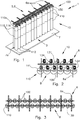
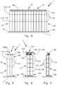
- Figs. 1 to 16 show embodiments of a bullet trap system 10 according to the invention in different views and in different degrees of detail.
- FIG. 1 schematically shows an embodiment of the bullet catching system 1 in a perspective view.
- the bullet catching system 1 comprises a bullet catching device 10, which comprises several bullet catching devices 100.
- the bullet catching devices 100 are according to FIG Fig. 1 equally trained.
- a bullet catching device 100 comprises three bullet catching modules or modules 110 for short.
- the modules 110 are arranged vertically on top of one another, adjacent to one another.
- the individual modules 110 are tubular or pot-shaped.
- each module 110 has a circular cylindrical wall 111 spaced about an axis.
- the bottom module 110 is closed with a bottom 112.
- the modules 110 arranged above do not have a floor 112.
- the wall 111 and the base 112 surround an interior space 113.
- a filling (not shown) is provided in the interior space 113.
- the filling is designed as granules, more precisely as polyurethane granules.
- the polyurethane granulate has a polygonal or polyhedron structure, so that a polygonal or or polyhedron-polyurethane granulate is provided as the filling.
- the individual granules have different contours and different grain sizes, are therefore irregular. Due to the shape of the granules, the granules wedge themselves, so that a wedge effect is created if the granules want to emerge through a limited opening like a penetration point. As a result, the granulate does not emerge from the penetration point that is dimensioned well above the maximum grain size of a granulate grain, without the action of additional force.
- the individual modules 110 are connected to one another via a connecting means 116 designed as a sleeve 115.
- the uppermost module 110a in each case is suspended via a suspension means 130.
- the bullet catching system 1 has a holding structure 5, here in the form of a ceiling-side rail unit 6.
- the rail unit 6 has several rails 6a connected in a grid-like manner, which have running rails for the suspension means 130.
- the suspension means 130 in some embodiments comprise an actuator 133 designed as a motor (see e.g. Fig. 2 and 6 ), via which the bullet catching devices 100 can be moved along the running rails.
- the suspension means 130 are designed such that the bullet catching devices 100 can be rotated about their axis. This is brought about by a corresponding rotary drive 134.
- the bullet catching devices 100 are in contact with a floor 7, more precisely with floor rails 7 a running on the floor 7, via floor units 140.
- the bullet catching devices 100 are supported and can be moved in a guided manner via these floor rails 7a.
- the bullet catching devices 100 are correspondingly supported on the floor via the floor units 7.
- the bullet catching devices 100 are arranged in two rows in the firing direction B and laterally offset from one another.
- an intermediate space located between two adjacent bullet catching devices 100 in a row is closed in the firing direction B by a bullet catching device 100 arranged offset thereto in the row behind it.
- the bullet catching devices 100 thus overlap transversely to the firing direction B, so that no gaps arise in the firing direction B.
- the modules 110 of a vertical arrangement have different lengths in the embodiment shown. A plurality of vertical arrangements are essentially the same or have the same design.
- Fig. 2 shows schematically in a top view an embodiment of an actuator-controlled bullet catching device 10, i.e. in a plan view an embodiment of the bullet catching device 10 with actuators 133.
- the bullet catching device 10 comprises eleven bullet catching devices 100 which are arranged in two rows in the firing direction B one behind the other.
- the bullet catching devices 100 overlap transversely, more precisely perpendicular, to the firing direction B. Gaps in the firing direction B for bullets are thus prevented.
- the bullet catching devices 100 are stored here individually and are individually adjustable. Actuators 133 are provided for this purpose.
- Fig. 3 shows schematically in a plan view an embodiment of a projectile catching device 10 according to Fig.1 .
- the bullet catching devices 100 are arranged in two rows with an otherwise identical or essentially identical design. In the embodiment shown, no actuators are provided.
- the projectile trapping devices 100 can be moved along the rails 6a.
- the bullet catching devices 100 are rotatably suspended by means of corresponding suspension means 130. The arrangement in two rows takes place in such a way that gaps in the firing direction B are prevented.
- Fig. 4 shows schematically in a front view the embodiment according to Fig. 1 . It can be clearly seen here that from the viewing direction (firing direction B) there are no gaps for the projectiles between the projectile interception devices 100, so that a closed projectile interception wall is formed.
- the floor units 140 can be clearly seen. These are stored or guided in corresponding floor or running rails 7a.
- Fig. 5 shows schematically in a side view the embodiment according to Fig. 4 .
- the arrangement in two rows in the firing direction B one behind the other can be seen here.
- Fig. 6 shows schematically in a side view the embodiment according to Fig. 4 .
- the arrangement in two rows in the firing direction B one behind the other can be seen here. Between bullet catching devices 100 of different rows there is an interspace which is prevented in the firing direction B due to the laterally offset arrangement of the bullet catching devices 100.
- the individual modules 110 are shown in FIG Fig. 5 about the same length.
- Fig. 7 shows schematically in a side view an embodiment of an individual projectile catching device 100 according to FIG Fig. 2 .
- the bullet catching device 100 is suspended via suspension means 130 and supported on the floor 7 by means of a floor unit 140.
- the details of the suspension means 130 are shown in detail view D in Fig. 8 and the details of the floor unit 140 in the detail view C in Fig. 9 shown.
- the modules 110 are formed here essentially of the same length.
- the individual modules 110 are connected to one another via connecting means 115.
- the modules 110 are designed to be approximately the same length.
- Fig. 8 shows schematically in a perspective detailed view a section D according to Fig. 7 .
- the suspension means 130 is shown here.
- the suspension means 130 comprises a joint 170 which is movably mounted in a running rail 6a.
- the joint 170 is designed as a bolt connection 171 so that it can be pivoted.
- the joint 170 is further connected to a swivel joint 180.
- the rotary joint 180 is coupled to the rotary drive 134, so that a rotation can be implemented by means of the rotary drive 134.
- a cover 119 of the module 110 is connected to the swivel joint 180.
- the cover 119 closes the module 110, the cover 119 being detachably connected to the module 110.
- Fig. 9 shows schematically in a front view the detail C according to FIG Fig. 7 .
- Detail C shows the floor unit 140.
- the floor unit 140 is connected to the floor 112 of the module 110, here by means of a pin 143.
- the pin 143 is rotatably mounted in the floor 112 by means of a pivot bearing 144.
- a further pin 145 with a roller 146 is provided on the bottom, protruding from the pin 143. This engages in a cross-sectionally C-shaped running rail or bottom rail 7a, the running roller 146 engaging laterally on the running rail or being designed to roll in this.
- Fig. 10 shows schematically in a front view the detail B according to Fig. 4 .
- Fig. 10 Another embodiment of the suspension means 130 is shown.
- the suspension is designed without an actuator.
- the rotary drive 134 which is connected to the uppermost module 110 via corresponding connecting means 116, moves in a rail 6a.
- a bolt-like part 136 is rotatably received in a sleeve-like receptacle 135.
- the sleeve-like receptacle 135 can be moved rotatably on the rail 6a.
- the bolt-like part 136 is connected to the uppermost module 110.
- the bolt-like part 136 of the suspension means 130 is detachably connected to the uppermost module 110, as in FIG Fig. 11 shown.
- Fig. 11 shows schematically in a front view detail B according to Fig. 4 and Fig. 8 in two different situations. Links in Fig. 11 the connected situation is shown, in which the module 110 is rotatably guided in the rail 6a via the suspension means 130. Right in the Fig. 11 the non-connected situation is shown. Here the suspension means are dismantled. A connection between rail 6a and module 110 is not implemented.
- Fig. 12 shows schematically in a perspective view a means for connecting two modules 110 of the projectile catching device 100.
- the means for connecting or connecting means 115 are shown as a sleeve 115.
- the sleeve 115 is designed like a ring and has a continuous inner wall 117, which is designed as a protrusion-free surface.
- the respective ends of the sleeve 115 are slightly beveled so that they can be inserted into the corresponding areas of the adjacent modules 110.
- Fig. 13 shows schematically in a perspective view a section in the area of detail B.
- the cover 119 of the respective module 110 is rotatably received on the respective rails 6a of the rail unit 6 via the suspension means 130, which comprise the rotary drive 134.
- Fig. 14 shows schematically an empty bullet trap module 110.
- the bullet trap module 110 according to FIG Fig. 14 is tubular with a wall 111 which surrounds an interior 113.
- the longest of the modules 110 is shown after Fig. 1 .
- the ratio of the length to the radius of the module and also to the diameter is greater than 1.
- Fig. 15 shows schematically overlapping possibilities of arranging the projectile catching devices 100, which are shown here only with the contour of the modules 110 for reasons of a better overview.
- the modules 110 have a diamond-shaped profile (top row on the right). Adjacent devices 100 are arranged next to one another in a row adjacent to one another. An overlap U is thus implemented in the firing direction B. An unhindered passage of a projectile in the firing direction B between the modules 110 is thus prevented.
- the modules 110 are honeycombed (hexagonal, lower row).
- an overlap area U of two modules 110 adjoining one another is implemented in the bombardment direction. In the case of a honeycomb arrangement, an offset is provided which requires a greater spatial depth.
- Fig. 16 shows schematically embodiments of a projectile interception module 110.
- the embodiment of the respectively essentially tubular shape can be selected as desired.
- a circular cylindrical shape, a tapering rectangular shape, a corrugated pipe shape and a cuboid shape of the module 110 are shown. These can be combined and arranged as desired.
Landscapes
- Engineering & Computer Science (AREA)
- General Engineering & Computer Science (AREA)
- Aiming, Guidance, Guns With A Light Source, Armor, Camouflage, And Targets (AREA)
Claims (11)
- Installation d'arrêt de projectile (100) pour un dispositif d'arrêt de projectile (10) pour un système d'arrêt de projectile (1), comprenant un module d'arrêt de projectile (110) destiné à absorber une énergie de projectile, qui présente une paroi (111) périphérique, dans laquelle la paroi (111) du module d'arrêt de projectile (110) est fabriquée à partir d'un matériau de module pouvant être traversé par des projectiles et un espace intérieur (113) entouré par la paroi (111) de manière périphérique est rempli d'un matériau de remplissage en tant que remplissage, dans laquelle la paroi (111) et/ou le remplissage est ou sont fabriqués à partir d'un polyuréthane et/ou le remplissage est réalisé sous la forme de granulés avec une structure polygonale ou polyédrique, caractérisée en ce que
au moins un autre module d'arrêt de projectile (110) est disposé sur le module d'arrêt de projectile (110, 110a), dans laquelle une liaison est prévue sur les côtés voisins des modules (110), afin d'obtenir ainsi une installation d'arrêt de projectile (100) comprenant plusieurs modules (110), dans laquelle un fond (112) est prévu sur au moins un module d'arrêt de projectile (110) le plus bas, de sorte qu'un remplissage dans l'installation d'arrêt de projectile (100) est maintenu, dans laquelle l'installation d'arrêt de projectile (100) présente en outre un module (110) dépourvu de fond, donc un module (100) sans fond, de sorte que le remplissage peut être déplacé du module (100) dépourvu de fond dans l'autre module (100). - Installation d'arrêt de projectile (100) selon la revendication 1, caractérisée en ce que
la liaison est réalisée sous la forme d'une bague, laquelle entoure les modules (110) voisins dans la zone sur les faces frontales de ceux-ci, de sorte qu'un intérieur des deux modules (110) dans une zone de liaison est débouchant. - Installation d'arrêt de projectile (100) selon la revendication 1 ou 2, caractérisée en ce que
une suspension est prévue sur le module (100) dépourvu de fond. - Installation d'arrêt de projectile (100) selon l'une quelconque des revendications précédentes 1 à 3, caractérisée en ce que
une unité fond (140) est prévue sur le module d'arrêt de projectile (110) présentant un fond (112), afin d'amener le module (110, 110a) au moins en contact avec un fond (7). - Installation d'arrêt de projectile (100) selon l'une quelconque des revendications précédentes 1 à 4, caractérisée en ce que
un manchon est prévu, lequel peut être enroulé autour de la paroi (111) d'un module d'arrêt de projectile (110) autour de celle-ci et fermé, de sorte que des ouvertures débouchantes de tir peuvent être enveloppées avec le manchon et peuvent donc être fermées, dans laquelle le manchon est fabriqué à partir d'un matériau flexible, pouvant être traversé par des projectiles. - Dispositif d'arrêt de projectile (10) pour un système d'arrêt de projectile (1), comprenant au moins deux installations d'arrêt de projectile (100) selon l'une quelconque des revendications précédentes 1 à 5, dans lequel les installations d'arrêt de projectile (100) sont disposées au moins par paires de manière décalée dans une direction de tir et/ou de manière décalée les unes des autres transversalement à celle-ci, dans lequel les installations d'arrêt de projectile (100) sont disposées de manière décalée les unes des autres de telle sorte que, vues dans la direction de tir (B), les installations d'arrêt de projectile (100) se chevauchent, de sorte que dans la direction de tir (B), aucun passage pour un projectile tiré dans la direction de tir (B) n'est présent.
- Dispositif d'arrêt de projectile (10) selon la revendication 6, caractérisé en ce que
les installations d'arrêt de projectile (100) sont disposées dans la direction de tir (B) en au moins deux rangées. - Dispositif d'arrêt de projectile (100) selon l'une quelconque des revendications précédentes 6 ou 7, caractérisé en ce que
au moins une suspension rotative est prévue, à laquelle l'installation d'arrêt de projectile (100) concernée est suspendue de manière rotative. - Système d'arrêt de projectile (1) destiné à recevoir des projectiles entraînant un impact avec absorption d'énergie des projectiles entraînant un impact, comprenant au moins une installation d'arrêt de projectile (100) selon l'une quelconque des revendications précédentes 1 à 5 et/ou au moins un dispositif d'arrêt de projectile (10) selon l'une quelconque des revendications précédentes 6 à 8, comprenant une structure de retenue (5) destinée à retenir au moins une installation d'arrêt de projectile (100) et/ou un dispositif d'arrêt de projectile (10), en particulier une structure de retenue (5) réalisée sous la forme d'une cabine avec fond porteur (7) et/ou plafond porteur.
- Procédé pour arrêter des projectiles dans un stand de tir ou similaire, avec une installation d'arrêt de projectile (100) selon l'une quelconque des revendications 1 à 5, un dispositif d'arrêt de projectile (10) selon les revendications 6 à 8, et/ou un système d'arrêt de projectile (1) selon la revendication 9, comprenant les étapes :
de réception d'au moins un projectile entraînant un impact par pénétration et absorption d'énergie dans l'installation d'arrêt de projectile (100), de re-fermeture de l'ouverture de pénétration produite par la pénétration, en particulier du fait des propriétés de re-fermeture de la paroi et/ou par déplacement du remplissage en direction de l'ouverture de pénétration et/ou enroulement de l'ouverture de pénétration avec un manchon et/ou rotation de l'installation d'arrêt de projectile (100) pourvue d'une ouverture de pénétration, de sorte qu'une zone sans ouverture de pénétration est tournée dans la direction de tir (B). - Utilisation de granulés de polymère-polyuréthane, en particulier de granulés d'élastomère-polyuréthane, dans un module d'arrêt de projectile (110) dans une installation d'arrêt de projectile (100) selon l'une quelconque des revendications 1 à 5, un dispositif d'arrêt de projectile (10) selon l'une quelconque des revendications 6 à 8 et/ou un système d'arrêt de projectile (1) selon la revendication 9 pour l'absorption d'énergie de projectiles.
Priority Applications (1)
| Application Number | Priority Date | Filing Date | Title |
|---|---|---|---|
| PL18188698T PL3444559T3 (pl) | 2017-08-18 | 2018-08-13 | Układ wychwytywania pocisków, urządzenie do wychwytywania pocisków, system wychwytywania pocisków i sposób i zastosowanie |
Applications Claiming Priority (1)
| Application Number | Priority Date | Filing Date | Title |
|---|---|---|---|
| DE102017118909.2A DE102017118909A1 (de) | 2017-08-18 | 2017-08-18 | Geschossauffangeinrichtung, Geschossauffangvorrichtung, Geschossfangsystem sowie Verfahren und Verwendung hierzu |
Publications (3)
| Publication Number | Publication Date |
|---|---|
| EP3444559A2 EP3444559A2 (fr) | 2019-02-20 |
| EP3444559A3 EP3444559A3 (fr) | 2019-05-08 |
| EP3444559B1 true EP3444559B1 (fr) | 2021-01-27 |
Family
ID=63254533
Family Applications (1)
| Application Number | Title | Priority Date | Filing Date |
|---|---|---|---|
| EP18188698.7A Active EP3444559B1 (fr) | 2017-08-18 | 2018-08-13 | Appareil de captage de balles, dispositif de captage de balles, système de captage de balles ainsi que procédé et utilisation correspondants |
Country Status (3)
| Country | Link |
|---|---|
| EP (1) | EP3444559B1 (fr) |
| DE (1) | DE102017118909A1 (fr) |
| PL (1) | PL3444559T3 (fr) |
Cited By (1)
| Publication number | Priority date | Publication date | Assignee | Title |
|---|---|---|---|---|
| EP4431860A1 (fr) * | 2023-03-16 | 2024-09-18 | Acia | Dispositif de freinage et de récupération de projectiles et système de ciblerie incluant un tel dispositif de freinage |
Families Citing this family (1)
| Publication number | Priority date | Publication date | Assignee | Title |
|---|---|---|---|---|
| CN117554014B (zh) * | 2023-10-20 | 2024-05-31 | 哈尔滨工程大学 | 用于大尺度跨介质水池重复使用的柔性拦截及测量装置 |
Family Cites Families (10)
| Publication number | Priority date | Publication date | Assignee | Title |
|---|---|---|---|---|
| EP0105284B1 (fr) * | 1982-03-12 | 1987-09-30 | Georg Fischer Aktiengesellschaft | Dispositif de blindage et son procede de fabrication |
| FR2747719A1 (fr) * | 1988-06-29 | 1997-10-24 | Francois Conversy | Dispositif de protection des abris contre l'impact direct des projectiles conventionnels |
| DE4006230A1 (de) * | 1990-02-28 | 1991-08-29 | Bke Bildtechnisches Konstrukti | Geschossfang |
| DE19506716C2 (de) * | 1994-03-05 | 1999-06-10 | Akzo Nobel Nv | Geschoßfangvorrichtung |
| DE19718810C2 (de) * | 1997-05-03 | 2003-03-27 | Tts Theissen Training Systems | Geschoßfangkammer |
| US8161710B2 (en) * | 2006-01-08 | 2012-04-24 | Specialty Hardware L.P. | Projectile-resistant wall structure with internal bag |
| DE202007008009U1 (de) * | 2007-06-05 | 2007-08-09 | Schrauber, Thomas, Dr. | Haltbarer Pfeilfang für Zielscheiben für Bogen und Armbrust |
| US7921759B2 (en) * | 2007-10-31 | 2011-04-12 | Armordynamics, Inc. | Apparatus for providing protection from ballistic rounds projectiles, fragments and explosives |
| DE202009015225U1 (de) | 2009-11-10 | 2010-03-25 | Bücheler, Gerd | Geschossfanganlage |
| DE202017101089U1 (de) * | 2017-02-27 | 2018-05-29 | Concept GmbH | Geschossfangmasse sowie Geschossfang |
-
2017
- 2017-08-18 DE DE102017118909.2A patent/DE102017118909A1/de not_active Withdrawn
-
2018
- 2018-08-13 EP EP18188698.7A patent/EP3444559B1/fr active Active
- 2018-08-13 PL PL18188698T patent/PL3444559T3/pl unknown
Non-Patent Citations (1)
| Title |
|---|
| None * |
Cited By (1)
| Publication number | Priority date | Publication date | Assignee | Title |
|---|---|---|---|---|
| EP4431860A1 (fr) * | 2023-03-16 | 2024-09-18 | Acia | Dispositif de freinage et de récupération de projectiles et système de ciblerie incluant un tel dispositif de freinage |
Also Published As
| Publication number | Publication date |
|---|---|
| EP3444559A2 (fr) | 2019-02-20 |
| EP3444559A3 (fr) | 2019-05-08 |
| DE102017118909A1 (de) | 2019-02-21 |
| PL3444559T3 (pl) | 2021-07-05 |
Similar Documents
| Publication | Publication Date | Title |
|---|---|---|
| DE102009032325A1 (de) | Schutzausstattung für Container, Container und Containerverbund | |
| EP1029217B1 (fr) | Dispositif d'arret de projectiles | |
| EP2834474B1 (fr) | Dispositif de sécurité destiné à un récipient contenant une masse oscillante | |
| EP3444559A2 (fr) | Dispositif de captage de balles, dispositif de captage de balles, système de captage de balles ainsi que procédé et utilisation correspondants | |
| DE3209644C2 (fr) | ||
| WO1996018434A1 (fr) | Dispositif pour eteindre des incendies de surface | |
| CH632083A5 (de) | Kuehlturm. | |
| EP3649426B1 (fr) | Système de paroi de protection contre les effets balistiques et procédé de montage dudit système de paroi | |
| DE682180C (fr) | ||
| DE202009015225U1 (de) | Geschossfanganlage | |
| DE69917448T2 (de) | Abbruchverfahren für gebäude und vorrichtung zur anwendung | |
| DE10221527B4 (de) | Geschossfangeinrichtung und Vorrichtung zur Durchführung von Wartungsarbeiten an derselben | |
| EP2877807B2 (fr) | Équipement de protection, véhicule et procédé de protection d'un objet | |
| DE4006230A1 (de) | Geschossfang | |
| DE102019107217B4 (de) | Schutzanordnung zur Verstärkung des Schutzes eines Containers | |
| DE102016111285A1 (de) | Panzerungselement zur Anordnung an einem Fahrzeug | |
| EP3396303B1 (fr) | Système de déclenchement d'avalanche | |
| DE19718810C2 (de) | Geschoßfangkammer | |
| EP3699388A1 (fr) | Grille de protection montée mobile et procédé permettant d'empêcher une tentative de vol | |
| DE19749881A1 (de) | Geschoßfangeinrichtung | |
| DE19504349C2 (de) | Tragelement, insbesondere für einen Doppel- oder Hohlraumboden | |
| EP1394496B1 (fr) | Collecteur de balles | |
| AT507092B1 (de) | Haltemittel für container | |
| DE102011013464A1 (de) | Mobile Feuerlöschübungsanlage in Form eines Flugzeugrumpfes | |
| WO2006007743A1 (fr) | Dispositif de levage pour la pose de treillis soudes pour beton arme transportables destines a la construction de plaques de beton et de murs de beton |
Legal Events
| Date | Code | Title | Description |
|---|---|---|---|
| PUAI | Public reference made under article 153(3) epc to a published international application that has entered the european phase |
Free format text: ORIGINAL CODE: 0009012 |
|
| STAA | Information on the status of an ep patent application or granted ep patent |
Free format text: STATUS: THE APPLICATION HAS BEEN PUBLISHED |
|
| AK | Designated contracting states |
Kind code of ref document: A2 Designated state(s): AL AT BE BG CH CY CZ DE DK EE ES FI FR GB GR HR HU IE IS IT LI LT LU LV MC MK MT NL NO PL PT RO RS SE SI SK SM TR |
|
| AX | Request for extension of the european patent |
Extension state: BA ME |
|
| PUAL | Search report despatched |
Free format text: ORIGINAL CODE: 0009013 |
|
| AK | Designated contracting states |
Kind code of ref document: A3 Designated state(s): AL AT BE BG CH CY CZ DE DK EE ES FI FR GB GR HR HU IE IS IT LI LT LU LV MC MK MT NL NO PL PT RO RS SE SI SK SM TR |
|
| AX | Request for extension of the european patent |
Extension state: BA ME |
|
| RIC1 | Information provided on ipc code assigned before grant |
Ipc: F41J 13/00 20090101AFI20190404BHEP |
|
| STAA | Information on the status of an ep patent application or granted ep patent |
Free format text: STATUS: REQUEST FOR EXAMINATION WAS MADE |
|
| 17P | Request for examination filed |
Effective date: 20190731 |
|
| RBV | Designated contracting states (corrected) |
Designated state(s): AL AT BE BG CH CY CZ DE DK EE ES FI FR GB GR HR HU IE IS IT LI LT LU LV MC MK MT NL NO PL PT RO RS SE SI SK SM TR |
|
| GRAP | Despatch of communication of intention to grant a patent |
Free format text: ORIGINAL CODE: EPIDOSNIGR1 |
|
| STAA | Information on the status of an ep patent application or granted ep patent |
Free format text: STATUS: GRANT OF PATENT IS INTENDED |
|
| INTG | Intention to grant announced |
Effective date: 20201116 |
|
| GRAS | Grant fee paid |
Free format text: ORIGINAL CODE: EPIDOSNIGR3 |
|
| GRAA | (expected) grant |
Free format text: ORIGINAL CODE: 0009210 |
|
| STAA | Information on the status of an ep patent application or granted ep patent |
Free format text: STATUS: THE PATENT HAS BEEN GRANTED |
|
| RAP1 | Party data changed (applicant data changed or rights of an application transferred) |
Owner name: RUBAHN, ANDREAS |
|
| RIN1 | Information on inventor provided before grant (corrected) |
Inventor name: RUBAHN, ANDREAS |
|
| AK | Designated contracting states |
Kind code of ref document: B1 Designated state(s): AL AT BE BG CH CY CZ DE DK EE ES FI FR GB GR HR HU IE IS IT LI LT LU LV MC MK MT NL NO PL PT RO RS SE SI SK SM TR |
|
| REG | Reference to a national code |
Ref country code: GB Ref legal event code: FG4D Free format text: NOT ENGLISH |
|
| REG | Reference to a national code |
Ref country code: CH Ref legal event code: EP |
|
| REG | Reference to a national code |
Ref country code: AT Ref legal event code: REF Ref document number: 1358752 Country of ref document: AT Kind code of ref document: T Effective date: 20210215 |
|
| REG | Reference to a national code |
Ref country code: IE Ref legal event code: FG4D Free format text: LANGUAGE OF EP DOCUMENT: GERMAN |
|
| REG | Reference to a national code |
Ref country code: DE Ref legal event code: R096 Ref document number: 502018003779 Country of ref document: DE |
|
| REG | Reference to a national code |
Ref country code: CH Ref legal event code: NV Representative=s name: NOVAGRAAF INTERNATIONAL SA, CH |
|
| REG | Reference to a national code |
Ref country code: NL Ref legal event code: FP |
|
| REG | Reference to a national code |
Ref country code: SE Ref legal event code: TRGR |
|
| REG | Reference to a national code |
Ref country code: NO Ref legal event code: T2 Effective date: 20210127 |
|
| REG | Reference to a national code |
Ref country code: LT Ref legal event code: MG9D |
|
| PG25 | Lapsed in a contracting state [announced via postgrant information from national office to epo] |
Ref country code: HR Free format text: LAPSE BECAUSE OF FAILURE TO SUBMIT A TRANSLATION OF THE DESCRIPTION OR TO PAY THE FEE WITHIN THE PRESCRIBED TIME-LIMIT Effective date: 20210127 Ref country code: FI Free format text: LAPSE BECAUSE OF FAILURE TO SUBMIT A TRANSLATION OF THE DESCRIPTION OR TO PAY THE FEE WITHIN THE PRESCRIBED TIME-LIMIT Effective date: 20210127 Ref country code: GR Free format text: LAPSE BECAUSE OF FAILURE TO SUBMIT A TRANSLATION OF THE DESCRIPTION OR TO PAY THE FEE WITHIN THE PRESCRIBED TIME-LIMIT Effective date: 20210428 Ref country code: BG Free format text: LAPSE BECAUSE OF FAILURE TO SUBMIT A TRANSLATION OF THE DESCRIPTION OR TO PAY THE FEE WITHIN THE PRESCRIBED TIME-LIMIT Effective date: 20210427 Ref country code: LT Free format text: LAPSE BECAUSE OF FAILURE TO SUBMIT A TRANSLATION OF THE DESCRIPTION OR TO PAY THE FEE WITHIN THE PRESCRIBED TIME-LIMIT Effective date: 20210127 Ref country code: PT Free format text: LAPSE BECAUSE OF FAILURE TO SUBMIT A TRANSLATION OF THE DESCRIPTION OR TO PAY THE FEE WITHIN THE PRESCRIBED TIME-LIMIT Effective date: 20210527 |
|
| PG25 | Lapsed in a contracting state [announced via postgrant information from national office to epo] |
Ref country code: LV Free format text: LAPSE BECAUSE OF FAILURE TO SUBMIT A TRANSLATION OF THE DESCRIPTION OR TO PAY THE FEE WITHIN THE PRESCRIBED TIME-LIMIT Effective date: 20210127 Ref country code: RS Free format text: LAPSE BECAUSE OF FAILURE TO SUBMIT A TRANSLATION OF THE DESCRIPTION OR TO PAY THE FEE WITHIN THE PRESCRIBED TIME-LIMIT Effective date: 20210127 |
|
| PG25 | Lapsed in a contracting state [announced via postgrant information from national office to epo] |
Ref country code: IS Free format text: LAPSE BECAUSE OF FAILURE TO SUBMIT A TRANSLATION OF THE DESCRIPTION OR TO PAY THE FEE WITHIN THE PRESCRIBED TIME-LIMIT Effective date: 20210527 |
|
| REG | Reference to a national code |
Ref country code: DE Ref legal event code: R097 Ref document number: 502018003779 Country of ref document: DE |
|
| PG25 | Lapsed in a contracting state [announced via postgrant information from national office to epo] |
Ref country code: EE Free format text: LAPSE BECAUSE OF FAILURE TO SUBMIT A TRANSLATION OF THE DESCRIPTION OR TO PAY THE FEE WITHIN THE PRESCRIBED TIME-LIMIT Effective date: 20210127 Ref country code: SM Free format text: LAPSE BECAUSE OF FAILURE TO SUBMIT A TRANSLATION OF THE DESCRIPTION OR TO PAY THE FEE WITHIN THE PRESCRIBED TIME-LIMIT Effective date: 20210127 |
|
| PG25 | Lapsed in a contracting state [announced via postgrant information from national office to epo] |
Ref country code: SK Free format text: LAPSE BECAUSE OF FAILURE TO SUBMIT A TRANSLATION OF THE DESCRIPTION OR TO PAY THE FEE WITHIN THE PRESCRIBED TIME-LIMIT Effective date: 20210127 Ref country code: DK Free format text: LAPSE BECAUSE OF FAILURE TO SUBMIT A TRANSLATION OF THE DESCRIPTION OR TO PAY THE FEE WITHIN THE PRESCRIBED TIME-LIMIT Effective date: 20210127 Ref country code: RO Free format text: LAPSE BECAUSE OF FAILURE TO SUBMIT A TRANSLATION OF THE DESCRIPTION OR TO PAY THE FEE WITHIN THE PRESCRIBED TIME-LIMIT Effective date: 20210127 |
|
| PLBE | No opposition filed within time limit |
Free format text: ORIGINAL CODE: 0009261 |
|
| STAA | Information on the status of an ep patent application or granted ep patent |
Free format text: STATUS: NO OPPOSITION FILED WITHIN TIME LIMIT |
|
| 26N | No opposition filed |
Effective date: 20211028 |
|
| PG25 | Lapsed in a contracting state [announced via postgrant information from national office to epo] |
Ref country code: AL Free format text: LAPSE BECAUSE OF FAILURE TO SUBMIT A TRANSLATION OF THE DESCRIPTION OR TO PAY THE FEE WITHIN THE PRESCRIBED TIME-LIMIT Effective date: 20210127 Ref country code: ES Free format text: LAPSE BECAUSE OF FAILURE TO SUBMIT A TRANSLATION OF THE DESCRIPTION OR TO PAY THE FEE WITHIN THE PRESCRIBED TIME-LIMIT Effective date: 20210127 |
|
| PG25 | Lapsed in a contracting state [announced via postgrant information from national office to epo] |
Ref country code: SI Free format text: LAPSE BECAUSE OF FAILURE TO SUBMIT A TRANSLATION OF THE DESCRIPTION OR TO PAY THE FEE WITHIN THE PRESCRIBED TIME-LIMIT Effective date: 20210127 |
|
| PG25 | Lapsed in a contracting state [announced via postgrant information from national office to epo] |
Ref country code: MC Free format text: LAPSE BECAUSE OF FAILURE TO SUBMIT A TRANSLATION OF THE DESCRIPTION OR TO PAY THE FEE WITHIN THE PRESCRIBED TIME-LIMIT Effective date: 20210127 |
|
| PG25 | Lapsed in a contracting state [announced via postgrant information from national office to epo] |
Ref country code: IS Free format text: LAPSE BECAUSE OF FAILURE TO SUBMIT A TRANSLATION OF THE DESCRIPTION OR TO PAY THE FEE WITHIN THE PRESCRIBED TIME-LIMIT Effective date: 20210527 |
|
| PG25 | Lapsed in a contracting state [announced via postgrant information from national office to epo] |
Ref country code: IE Free format text: LAPSE BECAUSE OF NON-PAYMENT OF DUE FEES Effective date: 20210813 |
|
| PG25 | Lapsed in a contracting state [announced via postgrant information from national office to epo] |
Ref country code: CY Free format text: LAPSE BECAUSE OF FAILURE TO SUBMIT A TRANSLATION OF THE DESCRIPTION OR TO PAY THE FEE WITHIN THE PRESCRIBED TIME-LIMIT Effective date: 20210127 |
|
| PG25 | Lapsed in a contracting state [announced via postgrant information from national office to epo] |
Ref country code: HU Free format text: LAPSE BECAUSE OF FAILURE TO SUBMIT A TRANSLATION OF THE DESCRIPTION OR TO PAY THE FEE WITHIN THE PRESCRIBED TIME-LIMIT; INVALID AB INITIO Effective date: 20180813 |
|
| PG25 | Lapsed in a contracting state [announced via postgrant information from national office to epo] |
Ref country code: MK Free format text: LAPSE BECAUSE OF FAILURE TO SUBMIT A TRANSLATION OF THE DESCRIPTION OR TO PAY THE FEE WITHIN THE PRESCRIBED TIME-LIMIT Effective date: 20210127 |
|
| PG25 | Lapsed in a contracting state [announced via postgrant information from national office to epo] |
Ref country code: MT Free format text: LAPSE BECAUSE OF FAILURE TO SUBMIT A TRANSLATION OF THE DESCRIPTION OR TO PAY THE FEE WITHIN THE PRESCRIBED TIME-LIMIT Effective date: 20210127 |
|
| PGFP | Annual fee paid to national office [announced via postgrant information from national office to epo] |
Ref country code: NL Payment date: 20250821 Year of fee payment: 8 Ref country code: LU Payment date: 20250820 Year of fee payment: 8 |
|
| PGFP | Annual fee paid to national office [announced via postgrant information from national office to epo] |
Ref country code: DE Payment date: 20250819 Year of fee payment: 8 |
|
| PGFP | Annual fee paid to national office [announced via postgrant information from national office to epo] |
Ref country code: NO Payment date: 20250820 Year of fee payment: 8 |
|
| PGFP | Annual fee paid to national office [announced via postgrant information from national office to epo] |
Ref country code: PL Payment date: 20250801 Year of fee payment: 8 Ref country code: IT Payment date: 20250829 Year of fee payment: 8 |
|
| PGFP | Annual fee paid to national office [announced via postgrant information from national office to epo] |
Ref country code: BE Payment date: 20250820 Year of fee payment: 8 Ref country code: GB Payment date: 20250822 Year of fee payment: 8 |
|
| PGFP | Annual fee paid to national office [announced via postgrant information from national office to epo] |
Ref country code: FR Payment date: 20250821 Year of fee payment: 8 Ref country code: AT Payment date: 20250819 Year of fee payment: 8 |
|
| PGFP | Annual fee paid to national office [announced via postgrant information from national office to epo] |
Ref country code: CH Payment date: 20250901 Year of fee payment: 8 Ref country code: SE Payment date: 20250821 Year of fee payment: 8 |
|
| PGFP | Annual fee paid to national office [announced via postgrant information from national office to epo] |
Ref country code: CZ Payment date: 20250801 Year of fee payment: 8 |
|
| PG25 | Lapsed in a contracting state [announced via postgrant information from national office to epo] |
Ref country code: TR Free format text: LAPSE BECAUSE OF FAILURE TO SUBMIT A TRANSLATION OF THE DESCRIPTION OR TO PAY THE FEE WITHIN THE PRESCRIBED TIME-LIMIT Effective date: 20210127 |