EP3444559A2 - Dispositif de captage de balles, dispositif de captage de balles, système de captage de balles ainsi que procédé et utilisation correspondants - Google Patents
Dispositif de captage de balles, dispositif de captage de balles, système de captage de balles ainsi que procédé et utilisation correspondants Download PDFInfo
- Publication number
- EP3444559A2 EP3444559A2 EP18188698.7A EP18188698A EP3444559A2 EP 3444559 A2 EP3444559 A2 EP 3444559A2 EP 18188698 A EP18188698 A EP 18188698A EP 3444559 A2 EP3444559 A2 EP 3444559A2
- Authority
- EP
- European Patent Office
- Prior art keywords
- projectile
- module
- collecting device
- filling
- bullet trap
- Prior art date
- Legal status (The legal status is an assumption and is not a legal conclusion. Google has not performed a legal analysis and makes no representation as to the accuracy of the status listed.)
- Granted
Links
Images


Classifications
-
- F—MECHANICAL ENGINEERING; LIGHTING; HEATING; WEAPONS; BLASTING
- F41—WEAPONS
- F41J—TARGETS; TARGET RANGES; BULLET CATCHERS
- F41J13/00—Bullet catchers
Definitions
- the invention relates to a projectile collecting device for a projectile collecting device for a bullet trap system according to claim 1.
- the invention also relates to a projectile collecting device for a bullet trap system according to claim 6.
- the invention relates to a bullet trap system for receiving impacting projectiles with energy consumption of the impacting projectiles according to claim 9.
- the invention also relates to a method for catching projectiles in a shooting range or the like according to claim 10.
- the invention relates to the use of a polymer-polyurethane granules in a plastic tube in a bullet trap according to claim 11.
- Bullet trap systems for shooting ranges are generally known from the state of the art. Such systems are provided to reduce the projectile energy projectiles in shooting ranges.
- a bullet trap comprising at least one, transverse to a firing direction extending, a bullet trap function filling, the bed of plastic and / or rubber particles and at least partially on the extending approximately parallel to the direction of bombardment bottom of a room rests.
- the invention includes the technical teaching that in a projectile collecting device for a projectile collecting device for a bullet trap, comprising a projectile module, short module, especially for absorbing a projectile energy, is provided, which has a wall, in particular a circumferential wall, wherein the wall of the Bullet collecting module is made of a penetrable by projectile module material and a surrounding of the wall circumferentially with a filling material is filled as filling, wherein the wall and / or the filling is made of a polyurethane or are and / or the filling as granules with a polygon is formed more precisely a polyhedron structure.
- a bullet catcher for a bullet trap projectile catcher comprising: a tubular bullet trap module, wherein a wall of the bullet catch module is made of bullet penetrable module material, the module is closed on the bottom side, one of Wall surrounding the interior is filled with a filling material, wherein the wall and the filling are made of a polyurethane and the filling is formed as granules, wherein at least one further module is arranged at the open end of the bottom-side closed module whose bottom side is formed open, so that the floor receiving device has at least one bottomless module and a module with a closed bottom, so that the respective interior of the two modules in the region of the connection is continuous, wherein at the bottom side opposite side of the u nteren module or between the modules, a connection is provided so as to produce the at least two modules comprehensive projectile collecting device.
- the bullet trap module has a bottom, so that the module is closed on the bottom side.
- the module is rotatably suspended.
- the module is suspended at an end remote from the bottom side.
- At least one further module is arranged on the bottom-side closed module, wherein at the bottom side opposite side is provided a connection with the corresponding bottom side of the rotatably suspended module, so as to produce a multi-module projectile collecting device.
- At least one further bullet trap module is arranged on the bullet trap module, wherein a connection is provided on the adjacent sides of the modules, so as to produce a multi-module bullet trap.
- the lowermost module is closed on the bottom side.
- the adjoining module is preferably not closed on the bottom side, so that the filling is movable from one module into the other module.
- at least two modules are closed on the bottom side.
- only the lowermost module is closed on the bottom side.
- the connection is designed such that the filling can be moved from one module into the adjacent module.
- the compound is annular, for example, designed as a collar or flange.
- the connection is arranged at least partially, preferably completely, on the outside of the adjacent, adjacent modules.
- the connection is at least partially on the inside and / or inside, preferably completely inside, provided.
- the projectile collecting device has a module with a bottom and a bottomless module, thus a module without bottom.
- the connection is preferably formed as a ring, more precisely as a flange-shaped ring. This surrounds the adjacent modules, in particular in the area at their adjacent end faces, so that an interior of the two modules in the connection area is continuous.
- the connection is preferably designed as a ring which has a circumferential flange on the inside or outside, preferably on the inside. In this way, a filling can pass from one module to the other or act on the filling in the other module.
- the bottomed module prevents the filling from leaving this module.
- the projectile collecting device is aligned vertically or obliquely to a horizontal or almost vertical. More preferably, the projectile receiving device is suspended. In this case, a suspension is provided on the bottomless module. The bottomless module forms the top of the two modules. Even more preferably, the projectile collecting device is suspended in such a way that a preferred impact surface is provided in the region of the bottomless or upper module.
- the modular structure thus results from a plurality of modules, the interior of which is fluidically and / or continuously interconnected and which can be replaced individually.
- An embodiment provides that the projectile collecting device is suspended above one of the bottomless modules.
- the projectile collecting device has a bottomed module and a plurality of bottomless modules which are mounted modularly on one another.
- the modules are connected to each other via the connection.
- the connection is designed so that the modules can be separated from each other.
- the connection is designed as a flange ring.
- two bottomless modules are provided.
- the middle module forms the module, which is arranged in the preferred hit area. Excessive damage to the respective module can be replaced by an undamaged module or prepared by means of a sleeve.
- the filling is preferably provided in all modules. As a result, a filling of an upper module due to gravity acts on the filling of a lower module.
- the filling which preferably consists of granules, continues to consist of recycled granules of PU, is abraded.
- the movement caused by a penetrating bullet, the granules and also deposited bullets are moved. Due to gravity, the movement is preferably directed in the effective direction of the heavy field, thus in the direction of the bottomed module.
- a bottom is provided on at least one projectile collecting module, in particular a lowermost or end-side projectile collecting module, so that a filling is held in the projectile collecting device.
- the filling can be moved in the direction of the ground with several modules. With vertical suspension, the filling can trickle towards the floor.
- a bottom unit is provided on the ground-floor projectile collecting module in order to bring the module at least in contact with a ground.
- the floor-mounted module has the floor unit remote from the suspended side of the suspended module.
- the floor unit is thus preferably arranged at the bottom of the module.
- the floor unit can be designed as a support, roller, wheel, bearing and the like.
- a sleeve is provided, which can be wrapped around the wall of a bullet collecting module around it and can be closed, so that with the cuff bullet holes can be wrapped and thus closed.
- the cuff may be made of a resilient material.
- the cuff is made of a rubbery material, such as natural rubber.
- the cuff is made from a material penetrable by the projectiles.
- the invention also includes the technical teaching that in a projectile collecting device for a bullet trap system, comprising at least two projectile receiving devices described herein, is provided that the projectile collecting devices offset at least in pairs in a firing direction and / or transversely, in particular vertically and / or horizontally, to offset the projectile receiving devices are arranged offset from one another in such a way that, viewed in the direction of firing, the projectile receiving devices overlap, so that there is no passage for a projectile fired in the direction of firing in the firing direction.
- the modules thus form an overlap area.
- One embodiment provides that the projectile collecting devices are arranged in the direction of firing in at least two rows.
- a further embodiment provides that at least one suspension, in particular a rotatable suspension, is preferably provided for each floor receiving device, on which the respective floor receiving device suspended, in particular rotatably suspended, is.
- the suspension is preferably manually and / or actuator-controlled rotatable and / or an adjustable locking to prevent rotation provided.
- the invention includes the technical teaching that is provided in a bullet trap for receiving impinging projectiles with energy consumption of the impinging projectiles, comprising at least one bullet trap described herein and / or at least one bullet trap described herein, that this holding a structure for holding at least one projectile receiving device and / or a projectile catching device, in particular a holding structure designed as a cabin with a supporting floor and / or load-bearing ceiling.
- the invention includes the technical teaching that is provided in a method for collecting projectiles in a shooting range or the like, in particular with a projectile collecting device described here, a projectile collecting device described herein and / or a bullet trap system described here, that this comprises the steps : Recording of at least one impacting bullet by penetration and energy dissipation into the or in the collecting tray, reclosing the penetration caused by the penetration, in particular by the reclosing properties of the wall and / or by moving the filling in the direction of penetration and / or wrapping the penetration opening with a sleeve and / or turning the provided with a penetration opening projectile collecting device, so that a region without penetration opening points in the direction of bombardment.
- the invention includes the technical teaching that a use of a polymer-polyurethane granules, preferably an elastomeric polyurethane granules is provided in a bullet trap module in a bullet trap system for energy absorption of floors.
- the projectile collecting device comprises at least one tubular projectile collecting module. That is, the module has a peripheral wall which circumferentially surrounds an interior space. In an axial direction, the module is preferably formed continuously.
- the profile of the module can be executed arbitrarily. For example, the profile is formed in a plan view annular, oval, polygonal, honeycomb, diamond-shaped or the like. When several modules are arranged side by side in a plan view, the modules overlap in a firing direction so that projectiles can pass non-adjacent modules.
- the module is preferably tubular or cup-shaped. In a cup-shaped design, a bottom is provided on the module, which prevents a movement of the filling.
- the wall surrounds a central axis of the module equidistant, so that the wall has a hollow cylindrical shape.
- Other cross sections such as rectangular, square, oval, polygonal or curved curves are possible.
- a ring-shaped or circular cross-section so that the wall is formed as a hollow cylinder.
- the wall has a wall thickness, which is designed so that impacting projectiles can penetrate these and in the surrounding of the wall inside - the interior - can get.
- the thickness of the wall is preferably in a range of at least about 8 mm to a maximum of about 12 mm.
- the wall is made of a plastic, for example made of polyurethane.
- the wall is preferably self-supporting.
- a framework for example in the form of a carrying skeleton.
- the scaffolding or skeleton is preferably constructed in lightweight construction, so that projectiles in your trajectory are not or only slightly influenced.
- An inner diameter of the module, in particular in hollow cylindrical design, is in a range of about 280 mm to 330 mm.
- the hollow cylindrical embodiment has a length of about 500 mm to 1500 mm.
- the single module has a bottom.
- at least the lowest module has a bottom.
- only one module is provided with a bottom, preferably the lowermost one in the case of vertical alignment.
- multiple modules or all modules can be floored.
- only the lowest module has a bottom.
- the wall is formed of a plastic.
- polyurethane and / or a rubbery material is used as a wall.
- the material used has a reclosing property.
- no scaffolding or support structures are provided.
- the module is thus self-supporting.
- a support structure is provided.
- the filling is designed as a rubbery material, preferably as a polyurethane.
- the filling is formed as granules, in particular formed as a polymer polyurethane granules.
- the granules on an irregular polygonal or polyhedral structure.
- shredded and / or recycled polyurethane granules are used as granules.
- the granules are arranged inside the module or modules. The granules can trickle in the direction of gravitational field with vertical arrangement of the modules. Due to the irregular polygon or polyhedron structure, the granules wedge during a trickle, so that there is only a limited amount of trickle.
- the granules When operated for a relatively long time, the granules are compacted when arranged vertically. Even with bombardment with corresponding bullets, the granules are rubbed and compacted. Due to the irregular polygon or polyhedron structure, the compression effect is counteracted.
- the bottom module in the case of a module with only one module, has a bottom.
- the floor can be made in one piece with the wall. In another embodiment, the floor is designed separately and connected to the wall finally, so that can get out of the interior no filling bottom side.
- the wall is preferably formed of polyurethane.
- the bottom is formed of polyurethane, preferably of a polymer, more particularly an elastomer, can be formed in a multi-part embodiment of a different material.
- the charge fills the volume of the interior to preferably at least 10 vol%, more preferably at least 20 vol%, and most preferably at least 30 vol%.
- the interior is completely or almost completely filled with the polymer or elastomer, resulting due to the polygonal or polyhedron structure gaps, the however, should not be taken into account when assessing the degree of filling.
- the fill level is more a level or fill level.
- the percentage refers to the distance from the bottom of the module to the level formed by the filling.
- the filling is made of a plastic, more precisely of an elastomer such as polyurethane.
- the filling is formed of the same material as the wall.
- the filling is in the form of granules. Other materials may be provided as a filling.
- the granules are formed as an elastomer having a hardness in a range of about 70-90 Shore plus / minus 5 Shore.
- An exemplary grain size is in a range of about 5 to 25 mm.
- a temperature resistance is about -40 ° C to 80 ° C, briefly up to 140 ° C.
- An exemplary bulk density is about 720 to 730 kg / m 3.
- the granules can be produced as virgin or as recycled granules.
- the granules are formed with a polygonal or polyhedron structure. A polygone or polyhedron structure makes it difficult for the filling to escape from the penetration openings since individual polygons or polyhedrons easily become wedged.
- the projectile collecting device is designed for a suspended attachment.
- the projectile collecting device on a suspension means.
- the suspension means is designed so that in the suspended state prevents rotation of the projectile collecting device or can be unlocked.
- a rotation can be realized, for example, manually or by means of an actuator.
- rotation by means of corresponding locking means is preferably limited or prevented.
- a limit is in a range of about 0 to 15 °, preferably about 0 to 10 °, and most preferably about 0 to 5 ° rotation.
- a refilling device is provided which is located above the topmost module in normal, suspended operation. In order to monitor the level or level of the projectile collecting device, for example, corresponding sensors are provided.
- corresponding regulation upon reaching a predetermined level value, refilling with corresponding granules is effected.
- corresponding granule storage containers are provided. These are located above the respective modules.
- the reservoirs are arranged protected in the projectile direction by diaphragms or other protection devices.
- the projectile collecting device can be expanded modularly.
- several modules can be provided, which also have a wall and a filling as the module described above.
- the bottom module has a bottom so that the filling does not trickle out of the module.
- further modules may have a bottom.
- the modules may be the same or substantially identical in terms of the other parameters.
- the modules are formed differently. Preferred are provided identically designed modules.
- the other modules are designed for attachment to the suspended module. For this, the other modules do not necessarily need hangers. Rather, the other modules have a connecting means, with which the module can be fastened to an adjacent side of the parent module in the hanging direction.
- connection means is a flange or flange in which the corresponding corresponding ends of the modules are received and secured.
- the connecting means can be made of any material.
- the connecting means is made of the same material as the wall of the modules.
- the respective connecting means is designed for a passage of the filling in the interior of the module.
- On a lowermost in the direction of hanging module a bottom unit is preferably provided.
- the floor unit may be designed as a floor storage and / or floor support.
- the suspended projectile collecting unit can be supported on a floor.
- paragraphs or protrusions are provided in some modules. These cause a flow restriction for the granules, so that a Nachrieseln is controlled.
- a sleeve is provided, which can be wrapped around the wall and set.
- the collar is preferably formed of a different material than the module.
- the collar is formed of a natural rubber.
- a preferred wall thickness of the sleeve is about 3mm.
- Preferred materials for the cuff are elastic materials to facilitate wrapping. Accordingly, a wall thickness must be selected accordingly.
- Preferred wall thicknesses range from 1 mm to 20 mm, more preferably from 2 mm to 10 mm, and most preferably around 3 mm.
- the cuff is of the same material made like the wall.
- the cuff may be provided loosely or attached to the wall. In a loose deployment, the cuff has a closure, for example in the form of a hook and loop fastener. If, on further bombardment, the penetration point on the sleeve is too large due to the multiplicity of penetration openings, so that the filling, despite wedge effect, leaves the projectile collecting device, the sleeve can be twisted and / or the module can be twisted.
- the module is rotated by a maximum of 180 °, so that a substantially Eindringö Stammschreib wall is provided in the direction of shooting. If a penetration point occurs here as well, which causes the filling to exit, then the procedure can be analogous to that described above.
- other cuffs can be placed around the existing cuffs. However, there is the danger here that at locations with less bombardment and thus fewer penetration openings, the wall thickness of the cuff and the wall becomes too large and the projectiles can no longer enter through the wall into the interior. In this respect, preferably only one sleeve is wound around a penetration point. The size of a cuff is individually interpretable.
- a length of the sleeve substantially corresponds to the circumference of the module, wherein an overlapping area for attachment and for providing a connecting means such as a hook and loop fastener and the elasticity are taken into account.
- a connecting means such as a hook and loop fastener and the elasticity are taken into account.
- only one sleeve is provided. If the cuff is damaged too much, its velcro can be opened and the cuff can be easily replaced. If a projectile collecting device is no longer suitable for bombardment due to too many or too large penetration points, the corresponding module can be removed and the filling together with the projectiles received can be moved out of the module. In this case, preferably, the contents of the bombarded module are distributed, for example, to a separation device which separates the filling of the penetrated floors.
- This separator may be formed as a sieve, as a magnet, as a liquid or the like.
- a separator is part of a bullet trap system.
- a projectile collecting device In order to provide a suitable projectile collecting device, this provides that a plurality of projectile collecting devices are provided. With a plurality of projectile receiving devices, a projectile collecting device can be realized which covers a larger area than a single projectile receiving device in the direction transverse, in particular perpendicular to a firing direction. In order to avoid that a gap is formed between two adjacent projectile receiving devices, through which Projectiles can pass unimpeded, a plurality of projectile receiving means are offset and / or arranged overlapping each other. In particular, a plurality of projectile receiving devices are formed at least in pairs in the direction of firing and / or transversely, in particular perpendicular thereto, offset from one another.
- the projectile collecting device can be arranged in several rows one behind the other, that is to say in the direction of bombardment.
- the devices or the modules are arranged in a row.
- the modules are arranged so that they realize an overlap in a plan view realize.
- the shape of the modules must be selected accordingly.
- the modules are formed in a diamond shape and / or a honeycomb shape. With a lateral adjacency of two adjacent modules thus an overlap is realized.
- the arrangement in a row a smaller depth of space is required.
- the projectile receiving devices are arranged in the shooting direction in two rows one behind the other.
- the arrangement takes place in such a way that behind each intermediate space two adjacent floor-receiving devices located in a front row each have a floor-receiving arrangement of the rear row, so that an intermediate space in the projectile direction is prevented by the overlapping.
- multiple rows are provided to respond to advancements in the field of weapons and / or ammunition and to provide higher projectile catch energy.
- the projectile collecting device is thus expandable, preferably modular expandable.
- the offset can be adjusted accordingly.
- an overlap of the projectile collecting devices in the direction of firing is preferably ensured.
- Other arrangements in which an overlap in the direction of bombing is realized can be made. For example, an arrangement according to a honeycomb structure or the like vorappelbar.
- the plurality of projectile receiving devices of a projectile collecting device are suspended and / or propped up on the ground, in one embodiment rotatable, in another embodiment arranged non-rotatably.
- the plurality of projectile receiving devices are coupled in a rotatable configuration for rotation or rotation with each other so that a plurality of projectile receiving devices can be rotated together.
- at least one projectile receiving device preferably several or all projectile receiving devices, is decoupled with respect to rotation. In this way, a lifetime of the projectile collecting device can be extended.
- the projectile collecting devices can be moved relative to each other. For example, centrally located projectile receiving devices can be moved to a more decentralized position.
- the respective suspension means and / or the Ground unit as a moving unit, for example as a role formed.
- a coupling and / or a decoupling of multiple projectile interceptors can be executed.
- the rotation about the respective axis and / or the method to other positions can be performed manually or by means of an actuator or actuator.
- a rail system is provided on the ceiling side and / or bottom side, which allows easy positioning or alignment.
- a controller can be provided which recognizes that a positioning and / or alignment is required and possibly performs this automatically.
- the projectile collecting device is preferably designed for bullet trap systems.
- a bullet trap system in addition to a projectile collecting device or a plurality of projectile collecting devices or a projectile collecting device or a plurality of projectile collecting devices, a holding structure on which the respective device or device is held.
- the system comprises a holding structure, which is preferably designed as a cabin, more precisely a bullet trap chamber, with a load-bearing floor and / or load-bearing ceiling.
- side walls, soundproofing measures and / or lighting etc. are provided in the system.
- the system includes a guard or shield that, for example, covers an upper portion in which the upper module is suspended from fire.
- This protection can for example also be designed as a privacy screen.
- this protection is designed as an upper panel, which serves as a high-aperture and / or height protection against fire. This protection thus ensures that bullets can not leave the bullet trap chamber.
- the projectiles are fired at a module. There, the projectiles penetrate the wall of the respective module, leaving behind a penetration opening. In the interior, the penetrated projectiles are slowed down by the filling, until they remain in the interior.
- the filling is provided as bulk material in the interior. The displacement through the projectile at least partially moves the filling. The filling also closes the penetration opening from the inside. If a number of penetration openings form a point of penetration, it is not possible to safely disperse the granules from a certain size despite the wedge effect of the polygonal or polyhedron granules. Therefore, in one embodiment, the penetration is prevented by wrapping with a cuff.
- the module is rotated so that a penetration-opening-free wall in the direction of firing points in the direction of firing.
- only one module is rotated.
- two adjacent modules are rotatably arranged to each other.
- all modules of a projectile receiving device are rotated together.
- a granulate of polyurethane For the filling a granulate of polyurethane is provided.
- a polymer-polyurethane granules Preferably, a polymer-polyurethane granules, more specifically an elastomeric polyurethane granules is provided. Due to the polygon or polyhedron structure a wedging effect is achieved.
- the shaping of the individual polyurethane granules is preferably formed differently.
- an elastomer is provided as the polymer, preferably an elastomeric polyurethane granules.
- a bullet trap system consisting of pipe segments, which can be brought by a compound to the desired length and are to be replaced individually when worn.
- the row behind it ensures an overlap in the edge areas. The number of rows depends on the energy of the projectiles (the higher the energy, the more rows are needed).
- the segments are open so that the granules can sag.
- the lowest element may have a floor or stand on a floor or possibly on / in a guide. For maximum durability, a natural rubber cuff can be attached around the damaged items.
- the tube segments can be rotated (whether manually or by motors), this is up to the user. This also applies to the rail system.
- a plurality of projectile receiving means comprising at least two different modules, hang vertically on a suspension downwards.
- this projectile collecting device is supported on a ground unit.
- the floor unit allows for moving and / or rotating the floor catcher about its vertical axis or axis of gravity. If one side of a floor catcher is damaged, the floor catcher is rotated over the suspension and the floor unit, so that an undamaged side or section is in the direction of firing. The rotation allows the floor catcher to be used longer without failing.
- the multi-hanging and upright projectile receiving devices realize a projectile curtain curtain. By staggered placement in different rows, the curtain is sufficiently leakproof for safe operation.
- a wall of the projectile collecting module is produced from a module material which can be penetrated by projectiles; the module is closed on the bottom side, surrounding it by the wall Interior with one Filling material is filled, wherein the wall and the filling are made of a polyurethane and the filling is formed as granules, wherein at least one further module is arranged at the open end of the bottom-side closed module whose bottom side is open, so that the projectile collecting device at least one bottomless module and a module with a closed bottom, so that the interior of the two modules in the region of the connection is continuous, wherein at the bottom side opposite side of the lower module or between the modules is provided a connection, so as to at least two modules produce comprehensive floor catcher.
- Fig. 1 to 16 show in various views and various degrees of detail embodiments of a projectile trapping system 10 according to the invention.
- Fig. 1 schematically shows in a perspective view of an embodiment of the bullet trap system 1.
- the bullet trap system 1 comprises a projectile collecting device 10, which comprises a plurality of projectile collecting devices 100.
- the projectile receiving devices 100 are according to Fig. 1 the same education.
- a projectile receiving device 100 each comprises three projectile collecting modules or modules 110 for short.
- the modules 110 are arranged vertically one above the other, adjacent to one another.
- the individual modules 110 are tubular or cup-shaped.
- each module 110 has a wall 111 which extends in the form of an annular ring about an axis and which extends at a distance from one axis.
- the lowermost module 110 is closed with a bottom 112.
- the overlying modules 110 have no bottom 112.
- the wall 111 and the bottom 112 surround an inner space 113.
- a filling (not shown) is provided in the inner space 113.
- the filling is designed as granules, more precisely as polyurethane granules.
- the polyurethane granules have a polygonal or polyhedron structure, so that a polygonal or polyurethane polyurethane granules is provided as a filling.
- the individual granules have different contours and different grain sizes are thus irregular. Due to the shape of the granules, the granules are wedged so that a wedge effect is produced when the granules try to escape through a restricted opening like a penetration point.
- the individual modules 110 are connected to each other via a respective connecting means 116 designed as a sleeve 115.
- the uppermost module 110a is suspended by a suspension means 130.
- the rail unit 6 has a plurality of lattice-like connected rails 6a, which have rails for the suspension means 130.
- the suspension means 130 comprise, in addition to a roller 131 or a plurality of rollers 131 in some embodiments, an actuator 133 designed as a motor (see eg Fig.
- the suspension means 130 are designed so that the projectile collecting devices 100 can rotate about their axis. This is effected by a corresponding rotary drive 134.
- the floor receiving devices 100 via floor units 140 are in contact with a floor 7, more precisely with floor rails 7a extending on the floor 7.
- the projectile collecting devices 100 are supported and guided movable.
- the floor receiving devices 100 are mounted on the bottom side via the ground units 7 accordingly.
- the projectile receiving devices 100 are arranged in two rows in the direction of bombardment B and laterally offset from one another.
- an intermediate space located between two adjacent projectile receiving devices 100 of a row is closed by a corresponding offset catcher 100 of the row behind it in the direction of bombardment B arranged offset thereto.
- the projectile receiving devices 100 thus overlap transversely to the direction of bombardment B, so that no clearances occur in the direction of bombardment B.
- the modules 110 of a vertical arrangement are formed differently long in the illustrated embodiment. Several vertical arrangements are substantially the same or identical.
- Fig.2 1 schematically shows a plan view of an embodiment of an actuator-controlled projectile collecting device 10, ie in a plan view an embodiment of the projectile collecting device 10 with actuators 133.
- the projectile collecting device 10 comprises eleven projectile receiving devices 100 which are arranged in two rows in the direction of bombardment B one behind the other. The projectile receiving devices 100 thereby overlap transversely, more precisely perpendicular, to the direction of bombardment B. Interspaces in the direction of bombardment B for projectiles are thus prevented.
- the projectile receiving devices 100 are stored here individually and are individually adjustable. For this purpose, actuators 133 are provided.
- Fig. 3 schematically shows a plan view of an embodiment of a projectile collecting device 10 according to Fig.1 .
- the projectile catching devices 100 are arranged in two rows with otherwise the same or substantially the same design. In the illustrated embodiment, no actuators are provided.
- the Geuntereinfang sharken 100 are movable along the rails 6a.
- the projectile trapping devices 100 are rotatably suspended via corresponding suspension means 130. The arrangement in two rows is such that gaps in the direction of bombing B are prevented.
- Fig. 4 schematically shows in a front view of the embodiment according to Fig. 1 , Here it can clearly be seen that from the viewing direction (shooting direction B) there are no intermediate spaces for the projectiles between the projectile catching devices 100, so that a closed projectile collecting wall is formed.
- the ground units 140 are clearly visible. These are stored or guided in corresponding floor or running rails 7a.
- Fig. 5 schematically shows in a side view of the embodiment according to Fig. 4 , Here, the arrangement in two rows in the direction of bombardment B can be seen in succession. Between projectile receiving devices 100 of different rows there is a gap that is prevented transversely to the direction of bombardment B due to the laterally offset arrangement of the projectile receiving devices 100.
- Fig. 6 schematically shows in a side view of the embodiment according to Fig. 4 , Here, the arrangement in two rows in the direction of bombardment B can be seen in succession. Between projectile receiving devices 100 of different rows there is a gap, which is prevented in the direction of bombardment B due to the laterally offset arrangement of the projectile receiving devices 100.
- the individual modules 110 are in contrast to the embodiment according to Fig. 5 formed about the same length.
- Fig. 7 schematically shows in a side view an embodiment of a single floor receiving device 100 according to Fig. 2 ,
- the projectile collecting device 100 is suspended by means of suspension means 130 and guided by means of ground unit 140 at the bottom 7.
- the details of the suspension means 130 are shown in detail D in FIG Fig. 8 and the details of the ground unit 140 in the detail view C in FIG Fig. 9 shown.
- the modules 110 are formed here substantially the same length.
- the individual modules 110 are connected to one another via connection means 115.
- the modules 110 are formed approximately the same length.
- Fig. 8 schematically shows a detail D in a perspective detail view Fig. 7 ,
- the suspension means 130 comprises a hinge 170 which is movably mounted in a running rail 6a.
- the hinge 170 is formed as a bolt connection 171, so that it is pivotable.
- the hinge 170 is further connected to a hinge 180.
- the rotary joint 180 is coupled to the rotary drive 134, so that a rotation by means of rotary drive 134 can be realized.
- a cover 119 of the module 110 is connected.
- the lid 119 closes the module 110, wherein the lid 119 is detachably connected to the module 110.
- Fig. 9 schematically shows the detail C in a front view Fig. 7
- Detail C shows the ground unit 140.
- the ground unit 140 is connected to the bottom 112 of the module 110, here by means of a pin 143.
- the pin 143 is rotatably mounted in the bottom 112 by means of a pivot bearing 144.
- a further pin 145 is provided with roller 146 on the bottom side. This engages in a C-shaped running rail or bottom rail 7a, wherein the roller 146 engages laterally on the running rail or is formed in this for unrolling.
- Fig. 10 schematically shows the detail B in a front view Fig. 4
- Fig. 10 another embodiment of the suspension means 130 is shown.
- the suspension is formed actuator-free.
- a rail 6a moves the rotary drive 134, which is connected via corresponding connecting means 116 with the uppermost module 110.
- a sleeve-like receptacle 135 In a sleeve-like receptacle 135, a bolt-like part 136 is rotatably received.
- the sleeve-like receptacle 135 is rotatably movable on the rail 6a.
- the bolt-like part 136 is connected to the uppermost module 110.
- the bolt-like part 136 of the suspension means 130 is detachably connected to the uppermost module 110, as in Fig. 11 shown.
- Fig. 11 shows schematically in a front view detail B after Fig. 4 and Fig. 8 in two different situations.
- Left in Fig. 11 shows the connected situation in which the module 110 is rotatably guided via the suspension means 130 in the rail 6a.
- Right in the Fig. 11 the unrelated situation is shown. Here the suspension is dismantled. A connection between rail 6a and module 110 is not realized.
- the means for connection or connecting means 115 are shown as a sleeve 115.
- the sleeve 115 is ring-shaped and has a continuous inner wall 117, which is formed as a projection-free surface.
- the respective ends of the sleeve 115 are slightly chamfered so that they can be inserted into the corresponding region of the adjacent modules 110.
- Fig. 13 schematically shows a perspective view of a detail in the area of the detail B.
- the cover 119 of the respective module 110 is rotatably received on the respective rails 6a of the rail unit 6 via the suspension means 130 which comprise the rotary drive 134.
- Fig. 14 schematically shows an empty projectile collecting module 110.
- the projectile collecting module 110 according to Fig. 14 is formed tubular with a wall 111 surrounding an interior 113. Shown is the longest of the modules 110 after Fig. 1 , The ratio of the length to the radius of the module and also to the diameter is greater than 1.
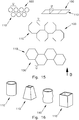
- Fig. 15 schematically shows overlapping arrangement possibilities of the projectile receiving devices 100, which is shown here for reasons of clarity only with the contour of the modules 110.
- the modules 110 have a diamond-shaped profile (upper row on the right). Adjacent devices 100 are juxtaposed in a row adjacent to one another. In Beschussplatz B thus an overlap U is realized. An unhindered passage of a projectile in shooting direction B between the modules 110 is thus prevented.
- the modules 110 are honeycombed (hexagonal, bottom row).
- an overlapping area U of two modules 110 adjoining one another is realized in the direction of bombardment.
- an offset is provided, which requires a greater spatial depth.
- Fig. 16 schematically shows embodiments of a projectile collecting module 110.
- the embodiment of each substantially tubular shape is arbitrary. Shown is a circular cylindrical shape, a tapered rectangular shape, a corrugated tube shape and a cuboid shape of the module 110. These can be combined and arranged arbitrarily.
Landscapes
- Engineering & Computer Science (AREA)
- General Engineering & Computer Science (AREA)
- Aiming, Guidance, Guns With A Light Source, Armor, Camouflage, And Targets (AREA)
Priority Applications (1)
| Application Number | Priority Date | Filing Date | Title |
|---|---|---|---|
| PL18188698T PL3444559T3 (pl) | 2017-08-18 | 2018-08-13 | Układ wychwytywania pocisków, urządzenie do wychwytywania pocisków, system wychwytywania pocisków i sposób i zastosowanie |
Applications Claiming Priority (1)
| Application Number | Priority Date | Filing Date | Title |
|---|---|---|---|
| DE102017118909.2A DE102017118909A1 (de) | 2017-08-18 | 2017-08-18 | Geschossauffangeinrichtung, Geschossauffangvorrichtung, Geschossfangsystem sowie Verfahren und Verwendung hierzu |
Publications (3)
| Publication Number | Publication Date |
|---|---|
| EP3444559A2 true EP3444559A2 (fr) | 2019-02-20 |
| EP3444559A3 EP3444559A3 (fr) | 2019-05-08 |
| EP3444559B1 EP3444559B1 (fr) | 2021-01-27 |
Family
ID=63254533
Family Applications (1)
| Application Number | Title | Priority Date | Filing Date |
|---|---|---|---|
| EP18188698.7A Active EP3444559B1 (fr) | 2017-08-18 | 2018-08-13 | Appareil de captage de balles, dispositif de captage de balles, système de captage de balles ainsi que procédé et utilisation correspondants |
Country Status (3)
| Country | Link |
|---|---|
| EP (1) | EP3444559B1 (fr) |
| DE (1) | DE102017118909A1 (fr) |
| PL (1) | PL3444559T3 (fr) |
Cited By (1)
| Publication number | Priority date | Publication date | Assignee | Title |
|---|---|---|---|---|
| CN117554014A (zh) * | 2023-10-20 | 2024-02-13 | 哈尔滨工程大学 | 用于大尺度跨介质水池重复使用的柔性拦截及测量装置 |
Families Citing this family (1)
| Publication number | Priority date | Publication date | Assignee | Title |
|---|---|---|---|---|
| FR3146730B1 (fr) * | 2023-03-16 | 2025-02-28 | Acia | Dispositif de freinage et de récupération de projectiles |
Family Cites Families (10)
| Publication number | Priority date | Publication date | Assignee | Title |
|---|---|---|---|---|
| EP0105284B1 (fr) * | 1982-03-12 | 1987-09-30 | Georg Fischer Aktiengesellschaft | Dispositif de blindage et son procede de fabrication |
| FR2747719A1 (fr) * | 1988-06-29 | 1997-10-24 | Francois Conversy | Dispositif de protection des abris contre l'impact direct des projectiles conventionnels |
| DE4006230A1 (de) * | 1990-02-28 | 1991-08-29 | Bke Bildtechnisches Konstrukti | Geschossfang |
| DE19506716C2 (de) * | 1994-03-05 | 1999-06-10 | Akzo Nobel Nv | Geschoßfangvorrichtung |
| DE19718810C2 (de) * | 1997-05-03 | 2003-03-27 | Tts Theissen Training Systems | Geschoßfangkammer |
| US8161710B2 (en) * | 2006-01-08 | 2012-04-24 | Specialty Hardware L.P. | Projectile-resistant wall structure with internal bag |
| DE202007008009U1 (de) * | 2007-06-05 | 2007-08-09 | Schrauber, Thomas, Dr. | Haltbarer Pfeilfang für Zielscheiben für Bogen und Armbrust |
| US7921759B2 (en) * | 2007-10-31 | 2011-04-12 | Armordynamics, Inc. | Apparatus for providing protection from ballistic rounds projectiles, fragments and explosives |
| DE202009015225U1 (de) | 2009-11-10 | 2010-03-25 | Bücheler, Gerd | Geschossfanganlage |
| DE202017101089U1 (de) * | 2017-02-27 | 2018-05-29 | Concept GmbH | Geschossfangmasse sowie Geschossfang |
-
2017
- 2017-08-18 DE DE102017118909.2A patent/DE102017118909A1/de not_active Withdrawn
-
2018
- 2018-08-13 EP EP18188698.7A patent/EP3444559B1/fr active Active
- 2018-08-13 PL PL18188698T patent/PL3444559T3/pl unknown
Cited By (2)
| Publication number | Priority date | Publication date | Assignee | Title |
|---|---|---|---|---|
| CN117554014A (zh) * | 2023-10-20 | 2024-02-13 | 哈尔滨工程大学 | 用于大尺度跨介质水池重复使用的柔性拦截及测量装置 |
| CN117554014B (zh) * | 2023-10-20 | 2024-05-31 | 哈尔滨工程大学 | 用于大尺度跨介质水池重复使用的柔性拦截及测量装置 |
Also Published As
| Publication number | Publication date |
|---|---|
| EP3444559B1 (fr) | 2021-01-27 |
| EP3444559A3 (fr) | 2019-05-08 |
| DE102017118909A1 (de) | 2019-02-21 |
| PL3444559T3 (pl) | 2021-07-05 |
Similar Documents
| Publication | Publication Date | Title |
|---|---|---|
| DE102009032325A1 (de) | Schutzausstattung für Container, Container und Containerverbund | |
| DE1800121C3 (de) | Vorrichtung zur definierten Positionierung von Abwurfkörpern, insbesondere Sprengladungen | |
| EP2020585B1 (fr) | Blindage de type SLAT mobile et de préférence amovible pour véhicules | |
| EP3444559B1 (fr) | Appareil de captage de balles, dispositif de captage de balles, système de captage de balles ainsi que procédé et utilisation correspondants | |
| EP2834474B1 (fr) | Dispositif de sécurité destiné à un récipient contenant une masse oscillante | |
| EP1029217B1 (fr) | Dispositif d'arret de projectiles | |
| DE3209644C2 (fr) | ||
| EP0143972A2 (fr) | Conteneur de pièces de monnaie pour machine déclenchée par pièces de monnaie ou pour machine faisant de la monnaie | |
| CH632083A5 (de) | Kuehlturm. | |
| DE682180C (fr) | ||
| DE202009015225U1 (de) | Geschossfanganlage | |
| EP2877807B1 (fr) | Équipement de protection, véhicule et procédé de protection d'un objet | |
| DE102019107217B4 (de) | Schutzanordnung zur Verstärkung des Schutzes eines Containers | |
| DE10221527B4 (de) | Geschossfangeinrichtung und Vorrichtung zur Durchführung von Wartungsarbeiten an derselben | |
| DE4006230A1 (de) | Geschossfang | |
| EP3396303B1 (fr) | Système de déclenchement d'avalanche | |
| DE102004021180A1 (de) | Filtereinheit, insbesondere Pulsfiltereinheit, Filterhaus und Filter sowie Verfahren zum Montieren einer Filtereinheit | |
| DE19749881A1 (de) | Geschoßfangeinrichtung | |
| DE19718810C2 (de) | Geschoßfangkammer | |
| AT507092B1 (de) | Haltemittel für container | |
| EP1394496B1 (fr) | Collecteur de balles | |
| EP3460138B1 (fr) | Dispositif de formation d'au moins une paroi, en particulier d'un bordé sur un navire | |
| AT520070B1 (de) | Netzförmige ineinander verschiebliche Kettenanordnung bei Discgolf-Körben | |
| DE202022104402U1 (de) | Geschossfangsystem | |
| EP2783773B1 (fr) | Dispositif et procédé d'extraction d'une brique de barbotage d'une paroi d'un récipient métallurgique |
Legal Events
| Date | Code | Title | Description |
|---|---|---|---|
| PUAI | Public reference made under article 153(3) epc to a published international application that has entered the european phase |
Free format text: ORIGINAL CODE: 0009012 |
|
| STAA | Information on the status of an ep patent application or granted ep patent |
Free format text: STATUS: THE APPLICATION HAS BEEN PUBLISHED |
|
| AK | Designated contracting states |
Kind code of ref document: A2 Designated state(s): AL AT BE BG CH CY CZ DE DK EE ES FI FR GB GR HR HU IE IS IT LI LT LU LV MC MK MT NL NO PL PT RO RS SE SI SK SM TR |
|
| AX | Request for extension of the european patent |
Extension state: BA ME |
|
| PUAL | Search report despatched |
Free format text: ORIGINAL CODE: 0009013 |
|
| AK | Designated contracting states |
Kind code of ref document: A3 Designated state(s): AL AT BE BG CH CY CZ DE DK EE ES FI FR GB GR HR HU IE IS IT LI LT LU LV MC MK MT NL NO PL PT RO RS SE SI SK SM TR |
|
| AX | Request for extension of the european patent |
Extension state: BA ME |
|
| RIC1 | Information provided on ipc code assigned before grant |
Ipc: F41J 13/00 20090101AFI20190404BHEP |
|
| STAA | Information on the status of an ep patent application or granted ep patent |
Free format text: STATUS: REQUEST FOR EXAMINATION WAS MADE |
|
| 17P | Request for examination filed |
Effective date: 20190731 |
|
| RBV | Designated contracting states (corrected) |
Designated state(s): AL AT BE BG CH CY CZ DE DK EE ES FI FR GB GR HR HU IE IS IT LI LT LU LV MC MK MT NL NO PL PT RO RS SE SI SK SM TR |
|
| GRAP | Despatch of communication of intention to grant a patent |
Free format text: ORIGINAL CODE: EPIDOSNIGR1 |
|
| STAA | Information on the status of an ep patent application or granted ep patent |
Free format text: STATUS: GRANT OF PATENT IS INTENDED |
|
| INTG | Intention to grant announced |
Effective date: 20201116 |
|
| GRAS | Grant fee paid |
Free format text: ORIGINAL CODE: EPIDOSNIGR3 |
|
| GRAA | (expected) grant |
Free format text: ORIGINAL CODE: 0009210 |
|
| STAA | Information on the status of an ep patent application or granted ep patent |
Free format text: STATUS: THE PATENT HAS BEEN GRANTED |
|
| RAP1 | Party data changed (applicant data changed or rights of an application transferred) |
Owner name: RUBAHN, ANDREAS |
|
| RIN1 | Information on inventor provided before grant (corrected) |
Inventor name: RUBAHN, ANDREAS |
|
| AK | Designated contracting states |
Kind code of ref document: B1 Designated state(s): AL AT BE BG CH CY CZ DE DK EE ES FI FR GB GR HR HU IE IS IT LI LT LU LV MC MK MT NL NO PL PT RO RS SE SI SK SM TR |
|
| REG | Reference to a national code |
Ref country code: GB Ref legal event code: FG4D Free format text: NOT ENGLISH |
|
| REG | Reference to a national code |
Ref country code: CH Ref legal event code: EP |
|
| REG | Reference to a national code |
Ref country code: AT Ref legal event code: REF Ref document number: 1358752 Country of ref document: AT Kind code of ref document: T Effective date: 20210215 |
|
| REG | Reference to a national code |
Ref country code: IE Ref legal event code: FG4D Free format text: LANGUAGE OF EP DOCUMENT: GERMAN |
|
| REG | Reference to a national code |
Ref country code: DE Ref legal event code: R096 Ref document number: 502018003779 Country of ref document: DE |
|
| REG | Reference to a national code |
Ref country code: CH Ref legal event code: NV Representative=s name: NOVAGRAAF INTERNATIONAL SA, CH |
|
| REG | Reference to a national code |
Ref country code: NL Ref legal event code: FP |
|
| REG | Reference to a national code |
Ref country code: SE Ref legal event code: TRGR |
|
| REG | Reference to a national code |
Ref country code: NO Ref legal event code: T2 Effective date: 20210127 |
|
| REG | Reference to a national code |
Ref country code: LT Ref legal event code: MG9D |
|
| PG25 | Lapsed in a contracting state [announced via postgrant information from national office to epo] |
Ref country code: HR Free format text: LAPSE BECAUSE OF FAILURE TO SUBMIT A TRANSLATION OF THE DESCRIPTION OR TO PAY THE FEE WITHIN THE PRESCRIBED TIME-LIMIT Effective date: 20210127 Ref country code: FI Free format text: LAPSE BECAUSE OF FAILURE TO SUBMIT A TRANSLATION OF THE DESCRIPTION OR TO PAY THE FEE WITHIN THE PRESCRIBED TIME-LIMIT Effective date: 20210127 Ref country code: GR Free format text: LAPSE BECAUSE OF FAILURE TO SUBMIT A TRANSLATION OF THE DESCRIPTION OR TO PAY THE FEE WITHIN THE PRESCRIBED TIME-LIMIT Effective date: 20210428 Ref country code: BG Free format text: LAPSE BECAUSE OF FAILURE TO SUBMIT A TRANSLATION OF THE DESCRIPTION OR TO PAY THE FEE WITHIN THE PRESCRIBED TIME-LIMIT Effective date: 20210427 Ref country code: LT Free format text: LAPSE BECAUSE OF FAILURE TO SUBMIT A TRANSLATION OF THE DESCRIPTION OR TO PAY THE FEE WITHIN THE PRESCRIBED TIME-LIMIT Effective date: 20210127 Ref country code: PT Free format text: LAPSE BECAUSE OF FAILURE TO SUBMIT A TRANSLATION OF THE DESCRIPTION OR TO PAY THE FEE WITHIN THE PRESCRIBED TIME-LIMIT Effective date: 20210527 |
|
| PG25 | Lapsed in a contracting state [announced via postgrant information from national office to epo] |
Ref country code: LV Free format text: LAPSE BECAUSE OF FAILURE TO SUBMIT A TRANSLATION OF THE DESCRIPTION OR TO PAY THE FEE WITHIN THE PRESCRIBED TIME-LIMIT Effective date: 20210127 Ref country code: RS Free format text: LAPSE BECAUSE OF FAILURE TO SUBMIT A TRANSLATION OF THE DESCRIPTION OR TO PAY THE FEE WITHIN THE PRESCRIBED TIME-LIMIT Effective date: 20210127 |
|
| PG25 | Lapsed in a contracting state [announced via postgrant information from national office to epo] |
Ref country code: IS Free format text: LAPSE BECAUSE OF FAILURE TO SUBMIT A TRANSLATION OF THE DESCRIPTION OR TO PAY THE FEE WITHIN THE PRESCRIBED TIME-LIMIT Effective date: 20210527 |
|
| REG | Reference to a national code |
Ref country code: DE Ref legal event code: R097 Ref document number: 502018003779 Country of ref document: DE |
|
| PG25 | Lapsed in a contracting state [announced via postgrant information from national office to epo] |
Ref country code: EE Free format text: LAPSE BECAUSE OF FAILURE TO SUBMIT A TRANSLATION OF THE DESCRIPTION OR TO PAY THE FEE WITHIN THE PRESCRIBED TIME-LIMIT Effective date: 20210127 Ref country code: SM Free format text: LAPSE BECAUSE OF FAILURE TO SUBMIT A TRANSLATION OF THE DESCRIPTION OR TO PAY THE FEE WITHIN THE PRESCRIBED TIME-LIMIT Effective date: 20210127 |
|
| PG25 | Lapsed in a contracting state [announced via postgrant information from national office to epo] |
Ref country code: SK Free format text: LAPSE BECAUSE OF FAILURE TO SUBMIT A TRANSLATION OF THE DESCRIPTION OR TO PAY THE FEE WITHIN THE PRESCRIBED TIME-LIMIT Effective date: 20210127 Ref country code: DK Free format text: LAPSE BECAUSE OF FAILURE TO SUBMIT A TRANSLATION OF THE DESCRIPTION OR TO PAY THE FEE WITHIN THE PRESCRIBED TIME-LIMIT Effective date: 20210127 Ref country code: RO Free format text: LAPSE BECAUSE OF FAILURE TO SUBMIT A TRANSLATION OF THE DESCRIPTION OR TO PAY THE FEE WITHIN THE PRESCRIBED TIME-LIMIT Effective date: 20210127 |
|
| PLBE | No opposition filed within time limit |
Free format text: ORIGINAL CODE: 0009261 |
|
| STAA | Information on the status of an ep patent application or granted ep patent |
Free format text: STATUS: NO OPPOSITION FILED WITHIN TIME LIMIT |
|
| 26N | No opposition filed |
Effective date: 20211028 |
|
| PG25 | Lapsed in a contracting state [announced via postgrant information from national office to epo] |
Ref country code: AL Free format text: LAPSE BECAUSE OF FAILURE TO SUBMIT A TRANSLATION OF THE DESCRIPTION OR TO PAY THE FEE WITHIN THE PRESCRIBED TIME-LIMIT Effective date: 20210127 Ref country code: ES Free format text: LAPSE BECAUSE OF FAILURE TO SUBMIT A TRANSLATION OF THE DESCRIPTION OR TO PAY THE FEE WITHIN THE PRESCRIBED TIME-LIMIT Effective date: 20210127 |
|
| PG25 | Lapsed in a contracting state [announced via postgrant information from national office to epo] |
Ref country code: SI Free format text: LAPSE BECAUSE OF FAILURE TO SUBMIT A TRANSLATION OF THE DESCRIPTION OR TO PAY THE FEE WITHIN THE PRESCRIBED TIME-LIMIT Effective date: 20210127 |
|
| PG25 | Lapsed in a contracting state [announced via postgrant information from national office to epo] |
Ref country code: MC Free format text: LAPSE BECAUSE OF FAILURE TO SUBMIT A TRANSLATION OF THE DESCRIPTION OR TO PAY THE FEE WITHIN THE PRESCRIBED TIME-LIMIT Effective date: 20210127 |
|
| PG25 | Lapsed in a contracting state [announced via postgrant information from national office to epo] |
Ref country code: IS Free format text: LAPSE BECAUSE OF FAILURE TO SUBMIT A TRANSLATION OF THE DESCRIPTION OR TO PAY THE FEE WITHIN THE PRESCRIBED TIME-LIMIT Effective date: 20210527 |
|
| PG25 | Lapsed in a contracting state [announced via postgrant information from national office to epo] |
Ref country code: IE Free format text: LAPSE BECAUSE OF NON-PAYMENT OF DUE FEES Effective date: 20210813 |
|
| PG25 | Lapsed in a contracting state [announced via postgrant information from national office to epo] |
Ref country code: CY Free format text: LAPSE BECAUSE OF FAILURE TO SUBMIT A TRANSLATION OF THE DESCRIPTION OR TO PAY THE FEE WITHIN THE PRESCRIBED TIME-LIMIT Effective date: 20210127 |
|
| PG25 | Lapsed in a contracting state [announced via postgrant information from national office to epo] |
Ref country code: HU Free format text: LAPSE BECAUSE OF FAILURE TO SUBMIT A TRANSLATION OF THE DESCRIPTION OR TO PAY THE FEE WITHIN THE PRESCRIBED TIME-LIMIT; INVALID AB INITIO Effective date: 20180813 |
|
| PG25 | Lapsed in a contracting state [announced via postgrant information from national office to epo] |
Ref country code: MK Free format text: LAPSE BECAUSE OF FAILURE TO SUBMIT A TRANSLATION OF THE DESCRIPTION OR TO PAY THE FEE WITHIN THE PRESCRIBED TIME-LIMIT Effective date: 20210127 |
|
| PG25 | Lapsed in a contracting state [announced via postgrant information from national office to epo] |
Ref country code: MT Free format text: LAPSE BECAUSE OF FAILURE TO SUBMIT A TRANSLATION OF THE DESCRIPTION OR TO PAY THE FEE WITHIN THE PRESCRIBED TIME-LIMIT Effective date: 20210127 |
|
| PGFP | Annual fee paid to national office [announced via postgrant information from national office to epo] |
Ref country code: NL Payment date: 20250821 Year of fee payment: 8 Ref country code: LU Payment date: 20250820 Year of fee payment: 8 |
|
| PGFP | Annual fee paid to national office [announced via postgrant information from national office to epo] |
Ref country code: DE Payment date: 20250819 Year of fee payment: 8 |
|
| PGFP | Annual fee paid to national office [announced via postgrant information from national office to epo] |
Ref country code: NO Payment date: 20250820 Year of fee payment: 8 |
|
| PGFP | Annual fee paid to national office [announced via postgrant information from national office to epo] |
Ref country code: PL Payment date: 20250801 Year of fee payment: 8 Ref country code: IT Payment date: 20250829 Year of fee payment: 8 |
|
| PGFP | Annual fee paid to national office [announced via postgrant information from national office to epo] |
Ref country code: BE Payment date: 20250820 Year of fee payment: 8 Ref country code: GB Payment date: 20250822 Year of fee payment: 8 |
|
| PGFP | Annual fee paid to national office [announced via postgrant information from national office to epo] |
Ref country code: FR Payment date: 20250821 Year of fee payment: 8 Ref country code: AT Payment date: 20250819 Year of fee payment: 8 |
|
| PGFP | Annual fee paid to national office [announced via postgrant information from national office to epo] |
Ref country code: CH Payment date: 20250901 Year of fee payment: 8 Ref country code: SE Payment date: 20250821 Year of fee payment: 8 |
|
| PGFP | Annual fee paid to national office [announced via postgrant information from national office to epo] |
Ref country code: CZ Payment date: 20250801 Year of fee payment: 8 |
|
| PG25 | Lapsed in a contracting state [announced via postgrant information from national office to epo] |
Ref country code: TR Free format text: LAPSE BECAUSE OF FAILURE TO SUBMIT A TRANSLATION OF THE DESCRIPTION OR TO PAY THE FEE WITHIN THE PRESCRIBED TIME-LIMIT Effective date: 20210127 |