EP3444575A1 - Dispositif capteur destiné à la mesure potentiometrique d'une hauteur de niveau de remplissage dans un recipient - Google Patents
Dispositif capteur destiné à la mesure potentiometrique d'une hauteur de niveau de remplissage dans un recipient Download PDFInfo
- Publication number
- EP3444575A1 EP3444575A1 EP18185383.9A EP18185383A EP3444575A1 EP 3444575 A1 EP3444575 A1 EP 3444575A1 EP 18185383 A EP18185383 A EP 18185383A EP 3444575 A1 EP3444575 A1 EP 3444575A1
- Authority
- EP
- European Patent Office
- Prior art keywords
- arrangement
- sensor arrangement
- container
- electrically conductive
- conductive element
- Prior art date
- Legal status (The legal status is an assumption and is not a legal conclusion. Google has not performed a legal analysis and makes no representation as to the accuracy of the status listed.)
- Granted
Links
Images

Classifications
-
- G—PHYSICS
- G01—MEASURING; TESTING
- G01F—MEASURING VOLUME, VOLUME FLOW, MASS FLOW OR LIQUID LEVEL; METERING BY VOLUME
- G01F23/00—Indicating or measuring liquid level or level of fluent solid material, e.g. indicating in terms of volume or indicating by means of an alarm
- G01F23/22—Indicating or measuring liquid level or level of fluent solid material, e.g. indicating in terms of volume or indicating by means of an alarm by measuring physical variables, other than linear dimensions, pressure or weight, dependent on the level to be measured, e.g. by difference of heat transfer of steam or water
- G01F23/24—Indicating or measuring liquid level or level of fluent solid material, e.g. indicating in terms of volume or indicating by means of an alarm by measuring physical variables, other than linear dimensions, pressure or weight, dependent on the level to be measured, e.g. by difference of heat transfer of steam or water by measuring variations of resistance of resistors due to contact with conductor fluid
-
- G—PHYSICS
- G01—MEASURING; TESTING
- G01F—MEASURING VOLUME, VOLUME FLOW, MASS FLOW OR LIQUID LEVEL; METERING BY VOLUME
- G01F23/00—Indicating or measuring liquid level or level of fluent solid material, e.g. indicating in terms of volume or indicating by means of an alarm
- G01F23/22—Indicating or measuring liquid level or level of fluent solid material, e.g. indicating in terms of volume or indicating by means of an alarm by measuring physical variables, other than linear dimensions, pressure or weight, dependent on the level to be measured, e.g. by difference of heat transfer of steam or water
-
- G—PHYSICS
- G01—MEASURING; TESTING
- G01F—MEASURING VOLUME, VOLUME FLOW, MASS FLOW OR LIQUID LEVEL; METERING BY VOLUME
- G01F23/00—Indicating or measuring liquid level or level of fluent solid material, e.g. indicating in terms of volume or indicating by means of an alarm
- G01F23/22—Indicating or measuring liquid level or level of fluent solid material, e.g. indicating in terms of volume or indicating by means of an alarm by measuring physical variables, other than linear dimensions, pressure or weight, dependent on the level to be measured, e.g. by difference of heat transfer of steam or water
- G01F23/26—Indicating or measuring liquid level or level of fluent solid material, e.g. indicating in terms of volume or indicating by means of an alarm by measuring physical variables, other than linear dimensions, pressure or weight, dependent on the level to be measured, e.g. by difference of heat transfer of steam or water by measuring variations of capacity or inductance of capacitors or inductors arising from the presence of liquid or fluent solid material in the electric or electromagnetic fields
- G01F23/263—Indicating or measuring liquid level or level of fluent solid material, e.g. indicating in terms of volume or indicating by means of an alarm by measuring physical variables, other than linear dimensions, pressure or weight, dependent on the level to be measured, e.g. by difference of heat transfer of steam or water by measuring variations of capacity or inductance of capacitors or inductors arising from the presence of liquid or fluent solid material in the electric or electromagnetic fields by measuring variations in capacitance of capacitors
-
- G—PHYSICS
- G01—MEASURING; TESTING
- G01N—INVESTIGATING OR ANALYSING MATERIALS BY DETERMINING THEIR CHEMICAL OR PHYSICAL PROPERTIES
- G01N27/00—Investigating or analysing materials by the use of electric, electrochemical, or magnetic means
- G01N27/26—Investigating or analysing materials by the use of electric, electrochemical, or magnetic means by investigating electrochemical variables; by using electrolysis or electrophoresis
- G01N27/28—Electrolytic cell components
- G01N27/30—Electrodes, e.g. test electrodes; Half-cells
- G01N27/301—Reference electrodes
Definitions
- the invention relates to a sensor arrangement for the potentiometric measurement of a level height in a container.
- Such sensor arrangements have been known for a long time and serve, for example, for measuring container contents in the chemical industry or in the food industry.
- the ratio of the voltage between an electrode end and the container wall or the counter electrode is measured to the voltage fed between the two electrode ends. This requires an at least low conductivity of the medium.
- the said potentiometric measuring method can also be physically realized via the dielectric behavior of the filling material, ie with the effect of its electrical capacitance.
- the oscillator arrangement which generates the alternating voltage has a certain parasitic capacitance to the electrode arrangement and the environment and due to virtually always existing asymmetries overcouples a common mode component of the alternating voltage in the measurement voltage.
- the measurement is very inaccurate because the parasitic capacitance of the oscillator assembly with the capacity of the filling material is comparable and therefore the error increases very much especially with decreasing level.
- parasitic capacitances, as z. B. arise by shielding, loading on the measurement signal.
- inductive interference can also be coupled into the measurement signal, in particular when using inductive components
- the object of the invention is to provide a solution, with the contents with a low dielectric constant, which is virtually electrically non-conductive, such as pure alcohol or deionized water, can be measured reliably, especially at low levels.
- a sensor arrangement for the potentiometric measurement of a level height in a container comprising an oscillator arrangement for generating an alternating voltage, wherein the oscillator arrangement at least partially in an electromagnetic shielding screen assembly is arranged, the potential of which depends on the potential of the container.
- the potential of the shield arrangement can be tracked to the potential of the container.
- a tracking device may be present, which tracks the potential of the shield arrangement to the potential of the container. Tracking here means that the potential of the screen assembly is coupled to the potential of the container via a predetermined equation or law. In particular, there may be a constant difference between the two.
- the shield arrangement can be at the potential of the container when the measurement signal is zero.
- the measurement signal may be zero, for example, when the oscillator assembly is not in operation or when the container has a certain level, such as completely full or completely empty.
- the test signal can also be artificially zeroed for verification.
- the oscillator arrangement may comprise an AC voltage source, wherein the AC voltage source is arranged in the shield arrangement in order to achieve a good shielding effect.
- the oscillator arrangement may comprise a transformer arrangement, wherein the transformer arrangement is arranged in the screen arrangement in order to achieve a good shielding effect.
- the oscillator arrangement can be arranged completely in the screen arrangement. As a result, the coupling to the outside is minimal.
- the entire electronics of the sensor arrangement is arranged in the screen arrangement.
- the oscillator arrangement is at least partially, preferably completely, arranged outside the electrode.
- the electrode can be made particularly small and compact. Other parts of the electronics can be arranged outside the electrode. In particular, only one current conductor of the oscillator arrangement and / or a return conductor serving for the voltage tapping may be arranged in the electrode.
- the shield arrangement can be connected to the container via an impedance converter.
- the impedance converter may be arranged in the shield arrangement.
- the impedance converter may be connected at an input to the container.
- the input can be high impedance.
- the impedance converter may be connected at its output to the shield arrangement.
- the output can be low impedance.
- the impedance converter may be a tracking device for tracking the potential of the screen assembly.
- the sensor arrangement can have an electrode which is connected to the oscillator arrangement and can be brought into the container so that it projects in particular out of the screen arrangement.
- a distal end of the electrode may be connected to an internal reference ground of the impedance converter. If, at the same time, the container is connected to the input of the impedance converter, a decoupled measuring signal can be tapped at the output, which has the internal reference ground as base potential.
- a current conductor of the oscillator arrangement and / or a return conductor serving for the voltage tap may be guided in the electrode with a short distance to a wall of the electrode, in particular via an insulation at the electrode. To prevent crosstalk between the two, you can be guided so that their distance from each other is maximum.
- the sensor arrangement may be designed so that a temperature measurement at the distal end of the electrode is possible.
- the sensor arrangement may comprise at least one first electrically conductive element made of a first material and at least one second electrically conductive element made of a second material, wherein the first electrically conductive element and the second electrically conductive element are arranged one behind the other along a current path, wherein a transition point between the first electrically conductive element and the second electrically conductive element is disposed at a distal end of the electrode and further transition points are arranged at at least one spaced from the distal end temperature reference point.
- Other transition points may be located outside the electrode or at an upper end of the electrode.
- Such further transition points may in particular have a constant temperature, for example by being tempered. By measuring the voltage between the two elements, a determination of the temperature is possible.
- an amplifier arrangement may be present.
- the first material may be constantan
- the second material may be stainless steel
- the sensor arrangement may have a DC filter for separating the DC voltage from the signal for the temperature measurement, since preferably only this is used to determine the temperature.
- the electrode may comprise the first electrically conductive element.
- a separate element can therefore be dispensed with.
- the first electrically conductive element may be formed by the electrode or at least by a part of the electrode.
- the sensor assembly may comprise a temperature sensing module having an input configured to tap the voltage between the first electrically conductive member and the second electrically conductive member, wherein an output signal representative of one output of the temperature sensing module for the temperature is.
- the raw signal may be directed to the outside and an analysis only take place outside.
- the sensor arrangement can have a filter module which filters out from the measurement voltage a component which is in phase with the oscillator arrangement and / or a phase-different component of the AC voltage. This makes it possible to analyze only the measurement signal or only the interference signal.
- Such a filter module can be realized, for example, with electrical components or designed as a software module in which only a separation of the in-phase and the phase-different component takes place in a software.
- the sensor arrangement can have an evaluation unit which evaluates the in-phase component and / or the phase-different component.
- the sensor arrangement may comprise a transformer having a primary side lying outside the screen assembly and a secondary side lying within the screen assembly.
- the primary side and the secondary side are galvanically separated from each other.
- an air gap may be present between the primary side and the secondary side.
- An electromagnetic coupling can take place via the air gap.
- a primary coil may be present
- a secondary coil may be present.
- the primary coil may have a shield, which may in particular be at the potential of the container.
- the secondary coil may have a shield which may be at the potential of the shield assembly.
- Each of the shields may in particular comprise a thin-layered metal film.
- Such a power supply can in particular also be configured wirelessly.
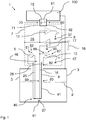
- a sensor arrangement 1 for the potentiometric measurement of a level height 2 in a container 3 is shown.
- an alternating voltage between an upper or proximal end 46 and a lower or distal end 45 of an electrode 4 is generated by an oscillator arrangement 5, which comprises an alternating current generator 51 and a transformer arrangement 52 (not shown).
- the electrode 4 protrudes into the container 3 and immersed in the contents, which is here for example a liquid, a.
- the fill level 2 can be determined by comparing the voltage drop between a lower electrode potential 27 and an upper electrode potential 28 with the voltage between the lower electrode potential 27 and the container 3 and the result is evaluated. Since these voltages are small, amplifiers 12 and 10 are used to process them for a subsequent evaluation circuit, for example with a ⁇ Processor with ADC.
- this is prevented or reduced, since the oscillator arrangement 5 is arranged within a screen arrangement 7, the potential of which is tracked to the potential of the container 3.
- the potential of the shield arrangement 7 is therefore dependent on the potential of the container 3. Although the parasitic capacitances are still there, they do not disturb the measurement due to the missing potential difference.
- the lower electrode potential 27 is connected to the internal reference ground 17 of an impedance converter 6.
- the input of the impedance converter 6 is connected to the potential 16 of the container 3, the container 3, because of its size, representing the environment well. It should be noted here that normally the container 3 is very large in relation to the sensor arrangement 1.
- the shield assembly 7 At the output of the impedance converter 6, the shield assembly 7 is connected. With a measurement signal of zero, the shield arrangement 7 is therefore at the same potential as the container 3.
- the entire sensor arrangement 1 lies within the screen arrangement 7, that is to say in an interior space 26 which is formed by the screen arrangement 7.
- An evaluation unit 100 is located outside the screen arrangement 7 and is connected to the sensor arrangement 1 via an energy transmission arrangement 60 with an energy transmission arrangement 61 and a power reception arrangement 62 and via a signal transmission arrangement 70 with a signal transmission arrangement 71 and a signal reception arrangement 72.
- the energy transmission arrangement 60 and the signal transmission arrangement 70 can each be designed such that transmission takes place without electrical contact, for example via light, in particular laser.
- the output of the impedance converter 6 is further connected to the input of a measuring signal amplifier 10, which amplifies and outputs the measuring signal.
- a reference of the measuring signal amplifier 10 here is a reference ground 37, which is equal to the internal reference ground 17.
- the level signal UL that is evaluated is the potential between the output of the measurement signal amplifier 10 and the internal reference ground 37 and 17, respectively.
- a return electrode 18 for the lower electrode potential 27 is made of a different material than the electrode 4.
- the return conductor 18 represents a first element 91 of a first material, such as Konstantan which is connected to a second element 92, namely a part 41 of the wall 44 of the electrode 4, which is made of a second material, such as stainless steel.
- the first element 91 and the second element 92 are connected to one another at a first transition point 81 located at the distal end 45 of the electrode 4 and lie behind one another along a current path 93.
- a second transition point 82 is located outside of the container 3 at the top or proximal end 46 of the electrode.
- a temperature measuring module 85 has a reference voltage amplifier 12 which amplifies the DC voltage measured between the first element 91 and the second element 92 and applied to the input 86.
- a filter module may also be present which filters out from the measuring voltage a component which is in phase with the oscillator arrangement and / or a phase-different portion of the alternating voltage.
- the in-phase component is the useful signal and the phase-different component is the interference component.
- Such Filter module can be realized by electrical components.
- a filtering process can also be done only with software.
- the return conductor 18 for the lower electrode potential 27 and the current conductor 25, with which the AC voltage is brought to the lower electrode potential 24, should be arranged as close as possible to the wall 44 of the electrode 4.
- the distance 19 between the two should be as large as possible to keep crosstalk low.
Landscapes
- Physics & Mathematics (AREA)
- General Physics & Mathematics (AREA)
- Thermal Sciences (AREA)
- Fluid Mechanics (AREA)
- Life Sciences & Earth Sciences (AREA)
- Chemical & Material Sciences (AREA)
- Power Engineering (AREA)
- Health & Medical Sciences (AREA)
- Engineering & Computer Science (AREA)
- Chemical Kinetics & Catalysis (AREA)
- Molecular Biology (AREA)
- Electromagnetism (AREA)
- Electrochemistry (AREA)
- Analytical Chemistry (AREA)
- Biochemistry (AREA)
- General Health & Medical Sciences (AREA)
- Immunology (AREA)
- Pathology (AREA)
- Measurement Of Levels Of Liquids Or Fluent Solid Materials (AREA)
Applications Claiming Priority (1)
| Application Number | Priority Date | Filing Date | Title |
|---|---|---|---|
| DE102017007946.3A DE102017007946A1 (de) | 2017-08-14 | 2017-08-14 | Sensoranordnung zur potentiometrischen Messung einer Füllstandshöhe in einem Behälter |
Publications (2)
| Publication Number | Publication Date |
|---|---|
| EP3444575A1 true EP3444575A1 (fr) | 2019-02-20 |
| EP3444575B1 EP3444575B1 (fr) | 2019-12-18 |
Family
ID=63047153
Family Applications (1)
| Application Number | Title | Priority Date | Filing Date |
|---|---|---|---|
| EP18185383.9A Active EP3444575B1 (fr) | 2017-08-14 | 2018-07-25 | Dispositif capteur destiné à la mesure potentiometrique d'une hauteur de niveau de remplissage dans un recipient |
Country Status (5)
| Country | Link |
|---|---|
| US (1) | US20190049282A1 (fr) |
| EP (1) | EP3444575B1 (fr) |
| CN (1) | CN109387260B (fr) |
| DE (1) | DE102017007946A1 (fr) |
| DK (1) | DK3444575T3 (fr) |
Citations (2)
| Publication number | Priority date | Publication date | Assignee | Title |
|---|---|---|---|---|
| US4188826A (en) * | 1977-05-27 | 1980-02-19 | Kernforschungsanlage Julich Gesellschaft Mit Beschrankter Haftung | Device for measuring the liquid level of an electrically conductive liquid |
| EP1067368A1 (fr) * | 1999-07-08 | 2001-01-10 | HELIOS AG Niveaumessung und Wägetechnik | Dispositif de mesure du niveau |
Family Cites Families (12)
| Publication number | Priority date | Publication date | Assignee | Title |
|---|---|---|---|---|
| US3114262A (en) * | 1959-05-15 | 1963-12-17 | Simmonds Precision Products | Volumetric gage for conductive liquids |
| SU1267164A1 (ru) * | 1984-04-24 | 1986-10-30 | Предприятие П/Я Ю-9877 | Потенциалометрический уровнемер |
| US5085526A (en) * | 1990-07-26 | 1992-02-04 | Astec International, Ltd. | Compact programmable temperature detector apparatus |
| DE10206463A1 (de) * | 2002-02-16 | 2003-09-11 | Grieshaber Vega Kg | Verfahren zum Betrieb eines Füllstandmessgerätes sowie Füllstandmessgerät |
| GB0417472D0 (en) * | 2004-08-05 | 2004-09-08 | Airbus Uk Ltd | Fuel tank system |
| DE102008054479A1 (de) * | 2008-12-10 | 2010-06-17 | Brita Gmbh | Leitfähigkeitsmessvorrichtung und Flüssigkeitsbehandlungsvorrichtung |
| DE102008043412A1 (de) * | 2008-11-03 | 2010-05-06 | Endress + Hauser Gmbh + Co. Kg | Vorrichtung zur Bestimmung und/oder Überwachung einer Prozessgröße eines Mediums |
| DE102009047697A1 (de) * | 2009-12-09 | 2011-06-16 | Robert Bosch Gmbh | Verfahren und Vorrichtung zur Erfassung einer Gasspezies |
| US9362832B2 (en) * | 2014-02-25 | 2016-06-07 | Telefonaktiebolaget L M Ericsson (Publ) | Intermediate bus architecture power supply |
| US20160003663A1 (en) * | 2014-07-03 | 2016-01-07 | Texas Instruments Incorporated | Capacitive liquid level measurement with differential out-of-phase channel drive to counteract human body capacitance |
| FR3040484B1 (fr) * | 2015-08-26 | 2019-01-25 | Akwel | Dispositif de mesure sans contact d'un niveau dans un reservoir |
| CN106768172A (zh) * | 2015-11-23 | 2017-05-31 | 北京航天试验技术研究所 | 极低相对介电常数介质液位测量实现方法 |
-
2017
- 2017-08-14 DE DE102017007946.3A patent/DE102017007946A1/de not_active Withdrawn
-
2018
- 2018-07-25 DK DK18185383.9T patent/DK3444575T3/da active
- 2018-07-25 EP EP18185383.9A patent/EP3444575B1/fr active Active
- 2018-08-10 US US16/100,219 patent/US20190049282A1/en not_active Abandoned
- 2018-08-14 CN CN201810919003.3A patent/CN109387260B/zh not_active Expired - Fee Related
Patent Citations (2)
| Publication number | Priority date | Publication date | Assignee | Title |
|---|---|---|---|---|
| US4188826A (en) * | 1977-05-27 | 1980-02-19 | Kernforschungsanlage Julich Gesellschaft Mit Beschrankter Haftung | Device for measuring the liquid level of an electrically conductive liquid |
| EP1067368A1 (fr) * | 1999-07-08 | 2001-01-10 | HELIOS AG Niveaumessung und Wägetechnik | Dispositif de mesure du niveau |
Non-Patent Citations (2)
| Title |
|---|
| FERRAN REVERTER ET AL: "Stability and accuracy of active shielding for grounded capacitive sensors", MEASUREMENT SCIENCE AND TECHNOLOGY., vol. 17, no. 11, 28 September 2006 (2006-09-28), GB, pages 2884 - 2890, XP055536781, ISSN: 0957-0233, DOI: 10.1088/0957-0233/17/11/004 * |
| WIKIPEDIA: "Buffer Amplifier", WIKIPEDIA, 6 June 2017 (2017-06-06), XP055536597, Retrieved from the Internet <URL:https://en.wikipedia.org/w/index.php?title=Buffer_amplifier&oldid=784124319> [retrieved on 20181219] * |
Also Published As
| Publication number | Publication date |
|---|---|
| EP3444575B1 (fr) | 2019-12-18 |
| CN109387260A (zh) | 2019-02-26 |
| DE102017007946A1 (de) | 2019-02-14 |
| DK3444575T3 (en) | 2020-03-16 |
| US20190049282A1 (en) | 2019-02-14 |
| CN109387260B (zh) | 2020-12-15 |
Similar Documents
| Publication | Publication Date | Title |
|---|---|---|
| DE102013005963B4 (de) | Kapazitiver Füllstandssensor | |
| EP0555710A2 (fr) | Dispositif de transfert de liquide pour appareil d'analyse | |
| DE19643698C2 (de) | Vorrichtung zur Abschirmung von für kapazitive Messungen verwendeten Leiterbahnen eines Kochfeldes | |
| EP3312600B1 (fr) | Capteur de conductivité et procédé de détermination de la conductivité électrique d'un milieu liquide | |
| DE112013006074T5 (de) | Kapazitiver Sensor, der dafür ausgelegt ist, ein Heizelement als Antennenelektrode zu verwenden | |
| EP3658925B1 (fr) | Procédé et dispositif d'essai pour la mesure d'impulsions de décharge partielle d'un câble blindé | |
| DE102010028718A1 (de) | Erfassung eines dielektrischen Objekts | |
| EP1837946A1 (fr) | Coupleur directionnel | |
| DE60109548T3 (de) | Geräuschbeständiger elektronischer Anwesenheitsdetektor | |
| EP3449226A1 (fr) | Elément de couplage pour un appareil de mesure de niveau de remplissage capacitif | |
| DE112016002011T5 (de) | Hauptwiderstands-Messvorrichtung | |
| DE102011078369B4 (de) | Kapazitive Sensoreinrichtung sowie Verfahren zum Kalibrieren einer kapazitiven Sensoreinrichtung | |
| EP3824323B1 (fr) | Détecteur servant à détecter du matériau électriquement conducteur | |
| DE102007003887A1 (de) | Verfahren zur Bedienung einer Vorrichtung zur kapazitiven Bestimmung und/oder Überwachung einer Prozessgröße | |
| DE102013018342A1 (de) | Kolbenzylindereinheit mit Auswerteeinheit zur Positionsbestimmung des Kolbens | |
| DE10205445B4 (de) | Kapazitives Füllstandmeßgerät | |
| EP3444575B1 (fr) | Dispositif capteur destiné à la mesure potentiometrique d'une hauteur de niveau de remplissage dans un recipient | |
| EP0711978B1 (fr) | Procédé et dispositif pour déterminer la position réelle d'un objet par balayage capacitif | |
| EP2763008A2 (fr) | Agencement de capteur capacitif et procédé de mesure capacitive avec compensation des capacités parasites | |
| WO2001061286A2 (fr) | Dispositif permettant de determiner le niveau de remplissage d'un agent dans un contenant | |
| EP0569572B1 (fr) | Procede pour la determination d'impedances electromagnetiques dans la gamme de frequences comprise entre 0 hz et 10 ghz | |
| DE3720473A1 (de) | Kapazitive fuellstandsmessung | |
| EP3489696A1 (fr) | Dispositif de mesure de courant, gamme de dispositifs de mesure de courant et procédé de mesure de courant | |
| DE102013224235B4 (de) | Sensorsystem zur kapazitiven Abstandsmessung | |
| DE102019120345B4 (de) | Detektionsvorrichtung insbesondere mit einklemmsensor |
Legal Events
| Date | Code | Title | Description |
|---|---|---|---|
| PUAI | Public reference made under article 153(3) epc to a published international application that has entered the european phase |
Free format text: ORIGINAL CODE: 0009012 |
|
| STAA | Information on the status of an ep patent application or granted ep patent |
Free format text: STATUS: THE APPLICATION HAS BEEN PUBLISHED |
|
| AK | Designated contracting states |
Kind code of ref document: A1 Designated state(s): AL AT BE BG CH CY CZ DE DK EE ES FI FR GB GR HR HU IE IS IT LI LT LU LV MC MK MT NL NO PL PT RO RS SE SI SK SM TR |
|
| AX | Request for extension of the european patent |
Extension state: BA ME |
|
| STAA | Information on the status of an ep patent application or granted ep patent |
Free format text: STATUS: REQUEST FOR EXAMINATION WAS MADE |
|
| STAA | Information on the status of an ep patent application or granted ep patent |
Free format text: STATUS: EXAMINATION IS IN PROGRESS |
|
| 17P | Request for examination filed |
Effective date: 20190528 |
|
| RBV | Designated contracting states (corrected) |
Designated state(s): AL AT BE BG CH CY CZ DE DK EE ES FI FR GB GR HR HU IE IS IT LI LT LU LV MC MK MT NL NO PL PT RO RS SE SI SK SM TR |
|
| 17Q | First examination report despatched |
Effective date: 20190625 |
|
| GRAP | Despatch of communication of intention to grant a patent |
Free format text: ORIGINAL CODE: EPIDOSNIGR1 |
|
| STAA | Information on the status of an ep patent application or granted ep patent |
Free format text: STATUS: GRANT OF PATENT IS INTENDED |
|
| INTG | Intention to grant announced |
Effective date: 20190819 |
|
| GRAS | Grant fee paid |
Free format text: ORIGINAL CODE: EPIDOSNIGR3 |
|
| GRAA | (expected) grant |
Free format text: ORIGINAL CODE: 0009210 |
|
| STAA | Information on the status of an ep patent application or granted ep patent |
Free format text: STATUS: THE PATENT HAS BEEN GRANTED |
|
| AK | Designated contracting states |
Kind code of ref document: B1 Designated state(s): AL AT BE BG CH CY CZ DE DK EE ES FI FR GB GR HR HU IE IS IT LI LT LU LV MC MK MT NL NO PL PT RO RS SE SI SK SM TR |
|
| REG | Reference to a national code |
Ref country code: CH Ref legal event code: EP |
|
| REG | Reference to a national code |
Ref country code: IE Ref legal event code: FG4D Free format text: LANGUAGE OF EP DOCUMENT: GERMAN |
|
| REG | Reference to a national code |
Ref country code: DE Ref legal event code: R096 Ref document number: 502018000528 Country of ref document: DE |
|
| REG | Reference to a national code |
Ref country code: AT Ref legal event code: REF Ref document number: 1215113 Country of ref document: AT Kind code of ref document: T Effective date: 20200115 |
|
| REG | Reference to a national code |
Ref country code: DK Ref legal event code: T3 Effective date: 20200311 |
|
| REG | Reference to a national code |
Ref country code: NL Ref legal event code: MP Effective date: 20191218 |
|
| PG25 | Lapsed in a contracting state [announced via postgrant information from national office to epo] |
Ref country code: SE Free format text: LAPSE BECAUSE OF FAILURE TO SUBMIT A TRANSLATION OF THE DESCRIPTION OR TO PAY THE FEE WITHIN THE PRESCRIBED TIME-LIMIT Effective date: 20191218 Ref country code: LV Free format text: LAPSE BECAUSE OF FAILURE TO SUBMIT A TRANSLATION OF THE DESCRIPTION OR TO PAY THE FEE WITHIN THE PRESCRIBED TIME-LIMIT Effective date: 20191218 Ref country code: NO Free format text: LAPSE BECAUSE OF FAILURE TO SUBMIT A TRANSLATION OF THE DESCRIPTION OR TO PAY THE FEE WITHIN THE PRESCRIBED TIME-LIMIT Effective date: 20200318 Ref country code: BG Free format text: LAPSE BECAUSE OF FAILURE TO SUBMIT A TRANSLATION OF THE DESCRIPTION OR TO PAY THE FEE WITHIN THE PRESCRIBED TIME-LIMIT Effective date: 20200318 Ref country code: FI Free format text: LAPSE BECAUSE OF FAILURE TO SUBMIT A TRANSLATION OF THE DESCRIPTION OR TO PAY THE FEE WITHIN THE PRESCRIBED TIME-LIMIT Effective date: 20191218 Ref country code: GR Free format text: LAPSE BECAUSE OF FAILURE TO SUBMIT A TRANSLATION OF THE DESCRIPTION OR TO PAY THE FEE WITHIN THE PRESCRIBED TIME-LIMIT Effective date: 20200319 Ref country code: LT Free format text: LAPSE BECAUSE OF FAILURE TO SUBMIT A TRANSLATION OF THE DESCRIPTION OR TO PAY THE FEE WITHIN THE PRESCRIBED TIME-LIMIT Effective date: 20191218 |
|
| REG | Reference to a national code |
Ref country code: LT Ref legal event code: MG4D |
|
| PG25 | Lapsed in a contracting state [announced via postgrant information from national office to epo] |
Ref country code: RS Free format text: LAPSE BECAUSE OF FAILURE TO SUBMIT A TRANSLATION OF THE DESCRIPTION OR TO PAY THE FEE WITHIN THE PRESCRIBED TIME-LIMIT Effective date: 20191218 Ref country code: HR Free format text: LAPSE BECAUSE OF FAILURE TO SUBMIT A TRANSLATION OF THE DESCRIPTION OR TO PAY THE FEE WITHIN THE PRESCRIBED TIME-LIMIT Effective date: 20191218 |
|
| PG25 | Lapsed in a contracting state [announced via postgrant information from national office to epo] |
Ref country code: AL Free format text: LAPSE BECAUSE OF FAILURE TO SUBMIT A TRANSLATION OF THE DESCRIPTION OR TO PAY THE FEE WITHIN THE PRESCRIBED TIME-LIMIT Effective date: 20191218 |
|
| PG25 | Lapsed in a contracting state [announced via postgrant information from national office to epo] |
Ref country code: NL Free format text: LAPSE BECAUSE OF FAILURE TO SUBMIT A TRANSLATION OF THE DESCRIPTION OR TO PAY THE FEE WITHIN THE PRESCRIBED TIME-LIMIT Effective date: 20191218 Ref country code: CZ Free format text: LAPSE BECAUSE OF FAILURE TO SUBMIT A TRANSLATION OF THE DESCRIPTION OR TO PAY THE FEE WITHIN THE PRESCRIBED TIME-LIMIT Effective date: 20191218 Ref country code: PT Free format text: LAPSE BECAUSE OF FAILURE TO SUBMIT A TRANSLATION OF THE DESCRIPTION OR TO PAY THE FEE WITHIN THE PRESCRIBED TIME-LIMIT Effective date: 20200513 Ref country code: RO Free format text: LAPSE BECAUSE OF FAILURE TO SUBMIT A TRANSLATION OF THE DESCRIPTION OR TO PAY THE FEE WITHIN THE PRESCRIBED TIME-LIMIT Effective date: 20191218 Ref country code: EE Free format text: LAPSE BECAUSE OF FAILURE TO SUBMIT A TRANSLATION OF THE DESCRIPTION OR TO PAY THE FEE WITHIN THE PRESCRIBED TIME-LIMIT Effective date: 20191218 |
|
| PG25 | Lapsed in a contracting state [announced via postgrant information from national office to epo] |
Ref country code: IS Free format text: LAPSE BECAUSE OF FAILURE TO SUBMIT A TRANSLATION OF THE DESCRIPTION OR TO PAY THE FEE WITHIN THE PRESCRIBED TIME-LIMIT Effective date: 20200418 Ref country code: SM Free format text: LAPSE BECAUSE OF FAILURE TO SUBMIT A TRANSLATION OF THE DESCRIPTION OR TO PAY THE FEE WITHIN THE PRESCRIBED TIME-LIMIT Effective date: 20191218 Ref country code: SK Free format text: LAPSE BECAUSE OF FAILURE TO SUBMIT A TRANSLATION OF THE DESCRIPTION OR TO PAY THE FEE WITHIN THE PRESCRIBED TIME-LIMIT Effective date: 20191218 |
|
| REG | Reference to a national code |
Ref country code: DE Ref legal event code: R097 Ref document number: 502018000528 Country of ref document: DE |
|
| PLBE | No opposition filed within time limit |
Free format text: ORIGINAL CODE: 0009261 |
|
| STAA | Information on the status of an ep patent application or granted ep patent |
Free format text: STATUS: NO OPPOSITION FILED WITHIN TIME LIMIT |
|
| PG25 | Lapsed in a contracting state [announced via postgrant information from national office to epo] |
Ref country code: ES Free format text: LAPSE BECAUSE OF FAILURE TO SUBMIT A TRANSLATION OF THE DESCRIPTION OR TO PAY THE FEE WITHIN THE PRESCRIBED TIME-LIMIT Effective date: 20191218 |
|
| 26N | No opposition filed |
Effective date: 20200921 |
|
| PG25 | Lapsed in a contracting state [announced via postgrant information from national office to epo] |
Ref country code: SI Free format text: LAPSE BECAUSE OF FAILURE TO SUBMIT A TRANSLATION OF THE DESCRIPTION OR TO PAY THE FEE WITHIN THE PRESCRIBED TIME-LIMIT Effective date: 20191218 |
|
| PG25 | Lapsed in a contracting state [announced via postgrant information from national office to epo] |
Ref country code: PL Free format text: LAPSE BECAUSE OF FAILURE TO SUBMIT A TRANSLATION OF THE DESCRIPTION OR TO PAY THE FEE WITHIN THE PRESCRIBED TIME-LIMIT Effective date: 20191218 Ref country code: MC Free format text: LAPSE BECAUSE OF FAILURE TO SUBMIT A TRANSLATION OF THE DESCRIPTION OR TO PAY THE FEE WITHIN THE PRESCRIBED TIME-LIMIT Effective date: 20191218 |
|
| REG | Reference to a national code |
Ref country code: BE Ref legal event code: MM Effective date: 20200731 |
|
| PG25 | Lapsed in a contracting state [announced via postgrant information from national office to epo] |
Ref country code: LU Free format text: LAPSE BECAUSE OF NON-PAYMENT OF DUE FEES Effective date: 20200725 |
|
| PG25 | Lapsed in a contracting state [announced via postgrant information from national office to epo] |
Ref country code: BE Free format text: LAPSE BECAUSE OF NON-PAYMENT OF DUE FEES Effective date: 20200731 |
|
| PG25 | Lapsed in a contracting state [announced via postgrant information from national office to epo] |
Ref country code: IE Free format text: LAPSE BECAUSE OF NON-PAYMENT OF DUE FEES Effective date: 20200725 |
|
| PG25 | Lapsed in a contracting state [announced via postgrant information from national office to epo] |
Ref country code: TR Free format text: LAPSE BECAUSE OF FAILURE TO SUBMIT A TRANSLATION OF THE DESCRIPTION OR TO PAY THE FEE WITHIN THE PRESCRIBED TIME-LIMIT Effective date: 20191218 Ref country code: MT Free format text: LAPSE BECAUSE OF FAILURE TO SUBMIT A TRANSLATION OF THE DESCRIPTION OR TO PAY THE FEE WITHIN THE PRESCRIBED TIME-LIMIT Effective date: 20191218 Ref country code: CY Free format text: LAPSE BECAUSE OF FAILURE TO SUBMIT A TRANSLATION OF THE DESCRIPTION OR TO PAY THE FEE WITHIN THE PRESCRIBED TIME-LIMIT Effective date: 20191218 |
|
| PG25 | Lapsed in a contracting state [announced via postgrant information from national office to epo] |
Ref country code: MK Free format text: LAPSE BECAUSE OF FAILURE TO SUBMIT A TRANSLATION OF THE DESCRIPTION OR TO PAY THE FEE WITHIN THE PRESCRIBED TIME-LIMIT Effective date: 20191218 |
|
| PGFP | Annual fee paid to national office [announced via postgrant information from national office to epo] |
Ref country code: IT Payment date: 20220729 Year of fee payment: 5 Ref country code: DK Payment date: 20220721 Year of fee payment: 5 |
|
| PGFP | Annual fee paid to national office [announced via postgrant information from national office to epo] |
Ref country code: FR Payment date: 20220725 Year of fee payment: 5 |
|
| PGFP | Annual fee paid to national office [announced via postgrant information from national office to epo] |
Ref country code: CH Payment date: 20220727 Year of fee payment: 5 |
|
| GBPC | Gb: european patent ceased through non-payment of renewal fee |
Effective date: 20220725 |
|
| PG25 | Lapsed in a contracting state [announced via postgrant information from national office to epo] |
Ref country code: GB Free format text: LAPSE BECAUSE OF NON-PAYMENT OF DUE FEES Effective date: 20220725 |
|
| REG | Reference to a national code |
Ref country code: DK Ref legal event code: EBP Effective date: 20230731 |
|
| REG | Reference to a national code |
Ref country code: CH Ref legal event code: PL |
|
| PG25 | Lapsed in a contracting state [announced via postgrant information from national office to epo] |
Ref country code: CH Free format text: LAPSE BECAUSE OF NON-PAYMENT OF DUE FEES Effective date: 20230731 |
|
| PG25 | Lapsed in a contracting state [announced via postgrant information from national office to epo] |
Ref country code: FR Free format text: LAPSE BECAUSE OF NON-PAYMENT OF DUE FEES Effective date: 20230731 |
|
| PG25 | Lapsed in a contracting state [announced via postgrant information from national office to epo] |
Ref country code: DK Free format text: LAPSE BECAUSE OF NON-PAYMENT OF DUE FEES Effective date: 20230731 |
|
| PG25 | Lapsed in a contracting state [announced via postgrant information from national office to epo] |
Ref country code: IT Free format text: LAPSE BECAUSE OF NON-PAYMENT OF DUE FEES Effective date: 20230725 Ref country code: DK Free format text: LAPSE BECAUSE OF NON-PAYMENT OF DUE FEES Effective date: 20230731 |
|
| REG | Reference to a national code |
Ref country code: AT Ref legal event code: MM01 Ref document number: 1215113 Country of ref document: AT Kind code of ref document: T Effective date: 20230725 |
|
| PG25 | Lapsed in a contracting state [announced via postgrant information from national office to epo] |
Ref country code: AT Free format text: LAPSE BECAUSE OF NON-PAYMENT OF DUE FEES Effective date: 20230725 |
|
| PG25 | Lapsed in a contracting state [announced via postgrant information from national office to epo] |
Ref country code: AT Free format text: LAPSE BECAUSE OF NON-PAYMENT OF DUE FEES Effective date: 20230725 |
|
| PGFP | Annual fee paid to national office [announced via postgrant information from national office to epo] |
Ref country code: DE Payment date: 20250722 Year of fee payment: 8 |
|
| PGFP | Annual fee paid to national office [announced via postgrant information from national office to epo] |
Ref country code: AT Payment date: 20260410 Year of fee payment: 5 |