EP3445155B1 - Mäher mit feststellbremse - Google Patents
Mäher mit feststellbremse Download PDFInfo
- Publication number
- EP3445155B1 EP3445155B1 EP17716961.2A EP17716961A EP3445155B1 EP 3445155 B1 EP3445155 B1 EP 3445155B1 EP 17716961 A EP17716961 A EP 17716961A EP 3445155 B1 EP3445155 B1 EP 3445155B1
- Authority
- EP
- European Patent Office
- Prior art keywords
- mower
- mowing
- cutting deck
- mower according
- cutting
- Prior art date
- Legal status (The legal status is an assumption and is not a legal conclusion. Google has not performed a legal analysis and makes no representation as to the accuracy of the status listed.)
- Active
Links
Images

Classifications
-
- A—HUMAN NECESSITIES
- A01—AGRICULTURE; FORESTRY; ANIMAL HUSBANDRY; HUNTING; TRAPPING; FISHING
- A01D—HARVESTING; MOWING
- A01D69/00—Driving mechanisms or parts thereof for harvesters or mowers
- A01D69/10—Brakes
-
- A—HUMAN NECESSITIES
- A01—AGRICULTURE; FORESTRY; ANIMAL HUSBANDRY; HUNTING; TRAPPING; FISHING
- A01D—HARVESTING; MOWING
- A01D34/00—Mowers; Mowing apparatus of harvesters
- A01D34/01—Mowers; Mowing apparatus of harvesters characterised by features relating to the type of cutting apparatus
- A01D34/412—Mowers; Mowing apparatus of harvesters characterised by features relating to the type of cutting apparatus having rotating cutters
- A01D34/63—Mowers; Mowing apparatus of harvesters characterised by features relating to the type of cutting apparatus having rotating cutters having cutters rotating about a vertical axis
- A01D34/67—Mowers; Mowing apparatus of harvesters characterised by features relating to the type of cutting apparatus having rotating cutters having cutters rotating about a vertical axis hand-guided by a walking operator
- A01D34/68—Mowers; Mowing apparatus of harvesters characterised by features relating to the type of cutting apparatus having rotating cutters having cutters rotating about a vertical axis hand-guided by a walking operator with motor driven cutters or wheels
- A01D34/6806—Driving mechanisms
- A01D34/6812—Braking or clutching mechanisms
-
- A—HUMAN NECESSITIES
- A01—AGRICULTURE; FORESTRY; ANIMAL HUSBANDRY; HUNTING; TRAPPING; FISHING
- A01D—HARVESTING; MOWING
- A01D34/00—Mowers; Mowing apparatus of harvesters
- A01D34/01—Mowers; Mowing apparatus of harvesters characterised by features relating to the type of cutting apparatus
- A01D34/412—Mowers; Mowing apparatus of harvesters characterised by features relating to the type of cutting apparatus having rotating cutters
- A01D34/63—Mowers; Mowing apparatus of harvesters characterised by features relating to the type of cutting apparatus having rotating cutters having cutters rotating about a vertical axis
- A01D34/74—Cutting-height adjustment
-
- A—HUMAN NECESSITIES
- A01—AGRICULTURE; FORESTRY; ANIMAL HUSBANDRY; HUNTING; TRAPPING; FISHING
- A01D—HARVESTING; MOWING
- A01D34/00—Mowers; Mowing apparatus of harvesters
- A01D34/01—Mowers; Mowing apparatus of harvesters characterised by features relating to the type of cutting apparatus
- A01D34/412—Mowers; Mowing apparatus of harvesters characterised by features relating to the type of cutting apparatus having rotating cutters
- A01D34/63—Mowers; Mowing apparatus of harvesters characterised by features relating to the type of cutting apparatus having rotating cutters having cutters rotating about a vertical axis
- A01D34/82—Other details
- A01D34/828—Safety devices
-
- A—HUMAN NECESSITIES
- A01—AGRICULTURE; FORESTRY; ANIMAL HUSBANDRY; HUNTING; TRAPPING; FISHING
- A01D—HARVESTING; MOWING
- A01D2101/00—Lawn-mowers
Definitions
- the present invention relates to an agricultural lawnmower provided with a brake, and more particularly to a parking brake.
- Agrarian mower means a lawnmower or brushcutter that can be used to maintain green spaces. Such a mower may be intended for professional use for the maintenance of public or private green spaces, or for domestic use for the maintenance of parks and gardens.
- the term parking brake means a brake that can be actuated to immobilize the mower when it is not in use.
- the brake can in particular be used to secure the mower parked on a slope, or to immobilize it on a vehicle during its transport.
- the invention finds applications for walk-behind mowers, for ride-on mowers, for remote-driving mowers or for stand-alone mowers. Finally, the invention finds applications both for electric motor mowers and for mowers with a heat engine.
- the present invention aims to provide a mower with a simple and reliable parking brake. Another object is to provide an economic parking brake requiring only a few additional members compared to a mower without such a brake.
- Another goal is to offer a mower with an electric or manual parking brake to operate the brake while securing the mower.
- the invention relates more precisely a mower comprising a frame, wheels for moving the mower according to a mowing plane, and a cutting housing.
- the mower is provided with a parking brake with at least one brake member integral with the cutting housing.
- the mowing deck is movably mounted on the frame between at least one mowing position and an immobilizing position of the mower in which the brake member comes into contact with at least one wheel of the mower to immobilize said wheel.
- Mowing plan means a plane parallel to which the mower can evolve when all its wheels are in contact with the ground. It is also a plan in which the mower is likely to cut the plants when all its wheels are placed on the ground.
- the mowing plan is a horizontal plane when the wheels of the mower are placed on a horizontal and level ground.
- the brake member immobilizes the wheel when it prevents its rotation by complementary form or when it exerts on the wheel a pressure to prevent the mower from moving, especially in a slope, under the effect of its own weight.
- a plurality of brake members may be provided on the mower deck to engage a plurality of mower wheels.
- the mower can be provided with two rear wheels having a fixed axis of rotation relative to the frame, and the cutting housing may comprise two brake members respectively associated with the two rear wheels.
- the term "fixed" rotation axis means the axis of rotation of a non-pivoting wheel.
- the front wheels may be pivoting or non-pivoting wheels.
- a pivoting wheel is understood to mean a wheel with an axis of rotation substantially parallel to the plane of section and a pivot axis substantially perpendicular to the plane of section, that is to say substantially vertical.
- the brake members may also be associated with one or more front wheels of the mower.
- the one or more brake members are configured to cooperate with the wheel, when the cutting deck is in the immobilization position, to immobilize the wheel.
- the cooperation between the brake member and the wheel may take place directly or through a complementary member integral with the rotation of the wheel.
- the one or more brake members may be configured to cooperate with one of a rim, a hub, a drum integral with the rim or hub, and a tread of the wheel.
- the tread may be formed by a tire equipping the wheel.
- the brake member may comprise, for example, a pad or a lug, capable of coming into contact with the wheel.
- the brake member is preferably a rigidly integral member of the cutting housing.
- the cutting housing may have a freedom of movement between the mowing position and the immobilization position, with a component parallel to the mowing plane.
- the mower deck can move, in this case, back and forth relative to the frame between the mowing position, or one of several mowing positions, and the immobilization position.
- immobilization is effected in this case by a displacement of the deck to the rear.
- the cutting deck may also have freedom of movement between the mowing position and the immobilization position, with a component perpendicular to the mowing plane .
- the cutting deck can move, in this case, from top to bottom relative to the frame. When the mower rests on a horizontal surface, this corresponds to a vertical component of the movement. The movement from top to bottom allows incidentally to adjust a cutting height in the mowing position or positions.
- the immobilization position is preferably a high position at the maximum of the stroke of the cutting housing with respect to the chassis and therefore in the position closest to the chassis, or a low position at the maximum of the race and therefore in the furthest position of the chassis.
- the cutting deck may have a freedom of movement between the mowing position and the immobilization position with a component parallel to the mowing plane and a component perpendicular to the plane of mowing. mowing, the parallel and perpendicular components being linked.
- the cutting deck can move, in this case, concomitantly from top to bottom and from front to back.
- the immobilization position is preferably a low position of the mowing deck, that is to say a position lower than the mowing position of the mower. low.
- a position of immobilization of the mower with a cutting deck at the bottom of its stroke relative to the frame, and therefore close to the ground, has a number of advantages. It lowers the center of gravity of the parked mower and reduces access to the blade or blades in the mower deck.
- the mower may advantageously comprise one of a ramp and a parallelogram of suspension of the cutting housing to the frame. These members allow relative movement of the cutting housing with respect to the frame in a movement comprising components parallel and perpendicular to the sectional plane bonded, as described above.
- the mower may include a mechanism for manually moving the mower deck between the mowing position and the immobilization position.
- One and the same lever can be provided to adjust both the cutting height of the mower, selecting a mowing position, and to actuate the parking brake, selecting the off position.
- the mower can still be provided with a latch configured to lock the mower deck in the down position.
- a lock makes it possible to guarantee the quality of the contact between the brake member and the wheel or wheels of the mower and to avoid an untimely release of the parking brake.
- the lock may be an indexed lock further configured to lock the cutting deck in several mowing positions, and in particular mowing positions corresponding to different cutting heights of the mower.
- the mower may further include a jack configured to move the mower deck between a continuous range of mowing positions and the off position.
- the cylinder is preferably an electric cylinder.
- a hydraulic cylinder is also possible.
- the mower of the invention can indeed be an electric mower. It may comprise, in this case, at least one electric motor driving at least one cutting blade of the cutting deck.
- the mower may further include at least one electric motor for advancing the mower coupled to the rear wheels.
- the drive motors blade and advancement of the mower can be powered including an electric storage battery.
- the figure 1 shows an electric lawn mower, walking type, in a mowing position. It comprises a tubular frame 10 on which are mounted different organs of the mower. Among the members mounted on the chassis 10, there may be noted in particular a foldable handlebar 12, non-pivoting rear wheels 14, front wheels 16 pivoting, a power supply battery 18 and a cutting housing 20. For simplicity of In the figure, other accessories of the mower, such as a collection of mowing reliefs, are not shown.
- front and rear are considered in relation to the normal direction of movement of the mower in operation, a driver walking from the mower moving behind the mower.
- the frame 10 is arranged substantially parallel to the lawn mower, that is to say substantially horizontally when the mower rests on its wheels and on a horizontal floor.
- the rear wheels 14 are integral with the frame with a freedom of rotation along an axis also parallel to the mowing plane. These are driving wheels coupled to an electric motor not visible on the figure 1 .
- the front wheels 16, arranged in pairs, have a freedom of rotation along an axis substantially parallel to the mowing plane and a pivotal freedom along an axis substantially perpendicular to the mowing plane.
- the cutting housing 20 is located substantially under the frame 10 between the front wheels 16 and the rear wheels 14. It houses one or more cutting blades not visible in the figure. These blades are driven by an electric motor 22 integral with the cutting housing.
- the cutting housing 20 is mounted on the frame 10 via a suspension parallelogram 24 formed in this example of four rods 26, three of which are visible at least partially in the figures.
- the rods 26 are articulated on both the chassis 10 and the mower deck 20 and thus give the mower deck 20 mobility relative to the chassis 10.
- the cutting deck 20 can thus be moved relative to the frame in a motion which comprises both a component perpendicular to the mowing plane, and a component parallel to the mowing plane.
- the displacement perpendicular to the mowing plane is designated by vertical displacement and the displacement parallel to the mowing plane is designated by horizontal displacement, with reference to the mower whose wheels are placed on a surface. floor plan and horizontal.
- the component of vertical displacement of the mower deck relative to the frame is used to adjust the cutting height of the mower, approaching more or less the mower deck.
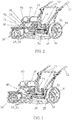
- the vertical displacement of the cutting deck can be indexed or not to define several mowing positions. This aspect is described in more detail in the remainder of the description, in particular with reference to the figure 2 .
- the vertical displacement of the cutting deck is accompanied by a pivoting rods relative to the frame and thus a horizontal displacement, related to the vertical movement.
- the point of articulation of each link on the frame is located at the rear of the point of articulation of the same link on the mower deck.
- a lowering of the cutting housing 20 relative to the chassis 10, in the direction of the ground is accompanied by a displacement of the cutting deck 20 towards the rear, approaching the rear wheels 14.
- This movement is used for the realization of the parking brake
- the cutting housing 20 in fact comprises brake members 30 engageable with the rear wheels 14 in the so-called immobilization position.
- a single brake member or a brake member for each rear wheel may be provided. Its operation is visible on Figures 2 and 3 .
- the figure 2 shows the mower deck in the down position.
- the cutting housing 20 extends in front of the rear wheels 14 and has a brake member 30.
- the brake member 30 comprises a contact end 32, in contact with the tread 34 of a rear wheel 14. It is positioned on the cutting housing near this wheel, so that a slight displacement of the cutting deck 20 rearward, authorized by the links 26, allows the contact end 32 of the brake member 30 to come into engagement with the tread 34 of the wheel 14. More precisely in the example illustrated, the contact end 32 of the brake member 30 engages in a relief of the tread 34 or in support on this tread.
- the contact end 32 may also be formed by a shoe capable of engaging the tread.
- the position of the cutting deck in which the brake member is applied against the wheel is the immobilization position.
- the brake member 30 and the part of the wheel with which it interacts in the immobilization position thus form a parking brake
- a similar brake member, not visible on the figure 2 can be provided for the other rear wheel.
- the figure 2 also shows a mechanism 40 for adjusting the position of the cutting housing 20 with respect to the chassis.
- the adjustment mechanism 40 comprises a pivoting adjustment lever 42 connected to the mower deck 20 via a connecting rod 44 articulated on the mower deck and on the adjustment lever.
- the adjustment lever 42 is manually operable to change the mowing position or to engage or release the immobilization position.
- the adjustment mechanism 40 also comprises a locking lug, not shown in the figure, integral with the adjustment lever 42 and associated with an indexing comb 50.
- the indexing comb 50 comprises a plurality of indexed positions, in the form of notches 52, in which the locking pin, loaded by a non-visible return spring, can come into engagement.
- each notch 52 corresponds a relative position of the cutting housing 20 relative to the frame 10, and a cutting height of the mower.
- the indexing comb 50 also comprises a notch or a stop 54 for locking the adjustment mechanism, and by means of this mechanism the cutting housing, in the immobilization position in which the or the brake members are applied against the wheels.
- the locking lug can be released from the notches 52 or the stopper 54 by an action on a handle 48 of the adjustment lever 42, against the return spring. This frees the adjustment lever to change the mowing position, engage the park position or release the park position.
- the figure 2 shows the adjustment lever 42 in the position corresponding to the immobilization position, the locking pin then cooperating with the stopper 54.
- the figure 3 shows another possibility of realization of a setting mechanism 40 in which the adjusting lever is replaced by an electric jack 60.
- the electric jack can then serve both to the displacement of the cutting deck between different mowing positions and the position immobilization and locking of the different positions.
- the mowing positions are not necessarily indexed, the height of the mower deck relative to the frame can be adjusted continuously.
Landscapes
- Life Sciences & Earth Sciences (AREA)
- Environmental Sciences (AREA)
- Harvester Elements (AREA)
Claims (15)
- Mäher, umfassend ein Gestell (10), Räder (14, 16) zur Verschiebung des Mähers gemäß einer Scherebene und ein Schneidegehäuse (20),
gekennzeichnet durch:- eine Feststellbremse mit zumindest einem Bremsorgan (30), das elnstücklg mit dem Schneidegehäuse (20) ist, und- dass das Schneidegehäuse (20) beweglich auf dem Gestell (10) zwischen zumindest einer Scherposition und einer immobilisierungsposition des Mähers, In der das Bremsorgan in Kontakt mit zumindest einem Rad (14) des Mähers kommt, um das Rad zu immobilisieren, montiert ist. - Mäher nach Anspruch 1, mit zwei Hinterrädern (14), die eine feste Drehachse in Bezug auf das Gestell aufweisen, wobei das Schneidegehäuse (20) zwei Bremsorgane (30) umfasst, die jeweils mit zwei Hinterrädern (14) verbunden sind.
- Mäher nach Anspruch 1 oder 2, wobei das Schneidegehäuse (20) eine Bewegungsfreiheit zwischen der Scherposition und der Immobilisierungsposition mit einer Komponente parallel zur Scherebene aufweist.
- Mäher nach einem der Ansprüche 1 bis 3, wobei das Schneidegehäuse (20) eine Bewegungsfreiheit zwischen der Scherposition und der immobilisierungsposition mit einer Komponente senkrecht zur Scherebene aufweist.
- Mäher nach einem der Ansprüche 1 oder 2, wobei das Schneidegehäuse (20) eine Bewegungsfreiheit zwischen der Scherposition und der Immobilisierungsposition mit einer Komponente parallel zur Scherebene und einer Komponente senkrecht zur Scherebene aufweist, wobei die parallele und die senkrechte Komponente verbunden sind.
- Mäher nach einem der Ansprüche 4 und 5, wobei die immobilisierungsposition eine untere Position des Schneidegehäuses (20) ist.
- Mäher nach einem der Ansprüche 1 bis 6, umfassend eines von einer Schräge und einer Parallelogrammaufhängung (24) des Schneidegehäuses (20) am Gestell (10).
- Mäher nach einem der vorhergehenden Ansprüche, umfassend einen Mechanismus (40) zur manuellen Verschiebung des Schneidegehäuses (20) zwischen der Scherposition und der Immobilisierungsposition.
- Mäher nach einem der vorhergehenden Ansprüche, umfassend eine Verriegelung (50), die konfiguriert Ist, um das Schneidegehäuse In der Immobilisierungsposition zu verriegeln.
- Mäher nach Anspruch 9, wobei die Verriegelung (50) eine gekoppelte Verriegelung Ist, die ferner konfiguriert ist, um das Schneidegehäuse (20) In mehreren Scherpositionen zu verriegeln.
- Mäher nach einem der vorhergehenden Ansprüche, umfassend einen Zylinder (60), der konfiguriert ist, um das Schneidegehäuse zwischen der Scherposition und der Immobilisierungsposition zu verschieben.
- Mäher nach einem der vorhergehenden Ansprüche, wobei das Bremsorgan (30) eines von einer Bremsbacke und einem Rastnocken (32) umfaset.
- Mäher nach einem der vorhergehenden Ansprüche, wobei das Bremsorgan konfiguriert ist, um mit einem von einer Felge, einer Radnabe und einer Lauffläche des Rads zu kooperieren.
- Mäher nach einem der vorhergehenden Ansprüche, umfassend einen elektrischen Motor (22) zum Antreiben von zumindest einer Schneidklinge des Schneidegehäuses.
- Mäher nach einem der Ansprüche 2 bis 14, umfassend einen elektrischen Motor zum Vortreiben des Mähers, der an die Hinterräder gekoppelt Ist.
Applications Claiming Priority (2)
| Application Number | Priority Date | Filing Date | Title |
|---|---|---|---|
| FR1653395A FR3050095B1 (fr) | 2016-04-18 | 2016-04-18 | Tondeuse agraire a frein de stationnement. |
| PCT/FR2017/050667 WO2017182725A1 (fr) | 2016-04-18 | 2017-03-22 | Tondeuse agraire à frein de stationnement |
Publications (2)
| Publication Number | Publication Date |
|---|---|
| EP3445155A1 EP3445155A1 (de) | 2019-02-27 |
| EP3445155B1 true EP3445155B1 (de) | 2019-12-04 |
Family
ID=56148494
Family Applications (1)
| Application Number | Title | Priority Date | Filing Date |
|---|---|---|---|
| EP17716961.2A Active EP3445155B1 (de) | 2016-04-18 | 2017-03-22 | Mäher mit feststellbremse |
Country Status (5)
| Country | Link |
|---|---|
| US (1) | US10716258B2 (de) |
| EP (1) | EP3445155B1 (de) |
| CN (1) | CN109068592A (de) |
| FR (1) | FR3050095B1 (de) |
| WO (1) | WO2017182725A1 (de) |
Families Citing this family (10)
| Publication number | Priority date | Publication date | Assignee | Title |
|---|---|---|---|---|
| US12426543B2 (en) | 2020-11-11 | 2025-09-30 | Techtronic Cordless Gp | Lawn mowers, detachable mower decks, and methods associated therewith |
| US12296694B2 (en) | 2021-03-10 | 2025-05-13 | Techtronic Cordless Gp | Lawnmowers |
| US12443180B2 (en) | 2021-11-10 | 2025-10-14 | Techtronic Cordless Gp | Robotic lawn mowers |
| AU2023200381A1 (en) | 2022-01-31 | 2023-08-17 | Techtronic Cordless Gp | Robotic garden tool |
| EP4270138A1 (de) | 2022-04-28 | 2023-11-01 | Techtronic Cordless GP | Erzeugung einer virtuellen grenze für ein robotisches gartenwerkzeug |
| US12472611B2 (en) | 2022-05-31 | 2025-11-18 | Techtronic Cordless Gp | Peg driver |
| AU2023204696A1 (en) | 2022-07-19 | 2024-02-08 | Techtronic Cordless Gp | Display for controlling robotic tool |
| AU2023206123A1 (en) | 2022-07-29 | 2024-02-15 | Techtronic Cordless Gp | Generation of a cryptography key for a robotic garden tool |
| CN115280958B (zh) * | 2022-08-02 | 2025-09-12 | 宁波领越智能设备有限公司 | 高度调节机构及包含其的割草机 |
| US20250081885A1 (en) * | 2022-09-06 | 2025-03-13 | Greenworks (Jiangsu) Co., Ltd. | Outdoor power machine |
Family Cites Families (20)
| Publication number | Priority date | Publication date | Assignee | Title |
|---|---|---|---|---|
| US4068452A (en) * | 1976-03-11 | 1978-01-17 | Allis-Chalmers Corporation | Mower spindle and spindle drive belt braking arrangement for rotary mower having plurality of mower spindles |
| US4120136A (en) * | 1976-12-27 | 1978-10-17 | Massey-Ferguson Inc. | Implement supporting and lifting linkage |
| US4322935A (en) * | 1980-09-08 | 1982-04-06 | Outboard Marine Corporation | Lawn mower including a safety clutch and brake |
| US4419857A (en) * | 1981-08-07 | 1983-12-13 | Outboard Marine Corporation | Lawn mower with combined engine brake and ignition control |
| EP0243560A1 (de) * | 1986-04-30 | 1987-11-04 | Jean-Jaques Osaer | Bremsvorrichtung für Rollschuhe |
| US5542241A (en) * | 1993-09-27 | 1996-08-06 | Garden Way Incoporated | Control for lawn mowers and the like and other wheeled walk behind powered apparatus |
| US6199354B1 (en) * | 1998-06-30 | 2001-03-13 | Honda Giken Kogyo Kabushiki Kaisha | Foot-operated parking brake for walk-behind power tool |
| JP3685680B2 (ja) * | 2000-03-30 | 2005-08-24 | 株式会社クボタ | 芝刈機 |
| JP3830454B2 (ja) * | 2003-02-10 | 2006-10-04 | 株式会社クボタ | 乗用草刈機 |
| WO2010030280A1 (en) * | 2008-09-12 | 2010-03-18 | Husqvarna U.S. Holding, Inc. | Mower with foot operated parking brake |
| US8511417B2 (en) * | 2008-11-18 | 2013-08-20 | Ted H. CORRIHER | Braking system for front caster wheels of a self-propelled vehicle |
| US8713903B2 (en) * | 2009-10-13 | 2014-05-06 | GXi Holdings, LLC | Brake assembly for power equipment |
| CN202535739U (zh) * | 2011-11-02 | 2012-11-21 | 浙江积体动力股份有限公司 | 一种具有割草高度调节装置的割草机 |
| CN102729961B (zh) * | 2012-07-23 | 2016-01-20 | 欧转喜 | 一种汽车应急制动器 |
| CN102849044B (zh) * | 2012-07-27 | 2014-04-16 | 浙江万安科技股份有限公司 | 一种气压盘式制动器用转化器 |
| HUE039546T2 (hu) * | 2013-03-15 | 2019-01-28 | Mtd Products Inc | Parkolófék rendszer botkormányos irányítású, zéró fordulási sugarú fûnyíróhoz |
| CN203246451U (zh) * | 2013-05-17 | 2013-10-23 | 刘元虎 | 刹车速停器 |
| CN203327540U (zh) * | 2013-05-20 | 2013-12-11 | 黄山学院 | 自适应式割草机 |
| CN103350725B (zh) * | 2013-07-23 | 2016-01-20 | 重庆润通科技有限公司 | 多功能骑式割草机 |
| CN103999627B (zh) * | 2014-04-30 | 2015-09-09 | 福州大学 | 智能割草机器人的机械结构装置 |
-
2016
- 2016-04-18 FR FR1653395A patent/FR3050095B1/fr not_active Expired - Fee Related
-
2017
- 2017-03-22 WO PCT/FR2017/050667 patent/WO2017182725A1/fr not_active Ceased
- 2017-03-22 CN CN201780024168.8A patent/CN109068592A/zh active Pending
- 2017-03-22 US US16/082,353 patent/US10716258B2/en active Active
- 2017-03-22 EP EP17716961.2A patent/EP3445155B1/de active Active
Non-Patent Citations (1)
| Title |
|---|
| None * |
Also Published As
| Publication number | Publication date |
|---|---|
| FR3050095B1 (fr) | 2018-04-06 |
| FR3050095A1 (fr) | 2017-10-20 |
| US10716258B2 (en) | 2020-07-21 |
| WO2017182725A1 (fr) | 2017-10-26 |
| US20190059228A1 (en) | 2019-02-28 |
| CN109068592A (zh) | 2018-12-21 |
| EP3445155A1 (de) | 2019-02-27 |
Similar Documents
| Publication | Publication Date | Title |
|---|---|---|
| EP3445155B1 (de) | Mäher mit feststellbremse | |
| EP0495713B1 (de) | Geländemotorfahrzeug für paraplektisch Behinderte | |
| EP1690446B1 (de) | Landwirtschaftliches Gerät für das Mähen von Produkten | |
| CA2370473C (fr) | Ameliorations a une tondeuse robotique | |
| EP2206425A1 (de) | Vorrichtung, die eine Heckenschere bildet und ein Zubehörteil für eine motorisierte Maschine, wie z.B. einen Aufsitzmäher, darstellt | |
| EP1148022A1 (de) | Rahmen für Hubgondel und Scherenhubgondel mit einem solchen Rahmen | |
| FR2782599A1 (fr) | Tondeuse a gazon autoportee legere, procede de fabrication et kit de mise en oeuvre | |
| FR2681216A1 (fr) | Vehicule permettant d'assurer le prelevement (coupe, ramassage et stockage) d'herbes ou produits similaires, et enceinte de stockage adaptable a des vehicules existants. | |
| EP0549777B1 (de) | Rasenmäher | |
| CH679765A5 (de) | ||
| EP2485977B1 (de) | Hebegerät für einen mäher mit extern montiertem heber | |
| FR2880771A1 (fr) | Machine agricole comportant un dispositif de reception pour le dispositif de transport demontable d'un outil porte, et dispositifs de reception et de transport correspondants | |
| EP2727877B1 (de) | Hydraulische Rasenmäher-Hubvorrichtung mit regulierbarer Breite | |
| FR2509118A1 (fr) | Faucheuse frontale portee a couteaux deplaces en mouvement de translation alternatif | |
| FR2809586A1 (fr) | Engin automoteur notamment pour operations de traitement et d'entretien de cultures | |
| FR2961469A1 (fr) | Vehicule porte-outil automoteur a 4 roues dissymetriques. | |
| FR3145527A1 (fr) | Système de levage et de stabilisation d’un vehicule | |
| FR3153986A1 (fr) | Engin de transport motorisé et adapté au passage d’obstacles | |
| FR3024014A1 (fr) | Machine de coupe comportant des moyens de reglage en inclinaison de ses moyens d'attelage. | |
| FR2991657A1 (fr) | Vehicule de transport automoteur a 3 roues | |
| FR2972184A1 (fr) | Dispositif de levage sous forme d'une colonne de levage | |
| BE886557A (fr) | Autochargeuse pour fourrages | |
| FR2887899A1 (fr) | Balayeuse montee a l'avant d'un vehicule pousseur/porteur de type quad | |
| FR3061891A1 (fr) | Colonne de direction a reglage manuel et retractable, pour un vehicule | |
| FR3070312A1 (fr) | Vehicule motorise multifonction |
Legal Events
| Date | Code | Title | Description |
|---|---|---|---|
| STAA | Information on the status of an ep patent application or granted ep patent |
Free format text: STATUS: UNKNOWN |
|
| STAA | Information on the status of an ep patent application or granted ep patent |
Free format text: STATUS: THE INTERNATIONAL PUBLICATION HAS BEEN MADE |
|
| PUAI | Public reference made under article 153(3) epc to a published international application that has entered the european phase |
Free format text: ORIGINAL CODE: 0009012 |
|
| STAA | Information on the status of an ep patent application or granted ep patent |
Free format text: STATUS: REQUEST FOR EXAMINATION WAS MADE |
|
| 17P | Request for examination filed |
Effective date: 20181025 |
|
| AK | Designated contracting states |
Kind code of ref document: A1 Designated state(s): AL AT BE BG CH CY CZ DE DK EE ES FI FR GB GR HR HU IE IS IT LI LT LU LV MC MK MT NL NO PL PT RO RS SE SI SK SM TR |
|
| AX | Request for extension of the european patent |
Extension state: BA ME |
|
| DAV | Request for validation of the european patent (deleted) | ||
| DAX | Request for extension of the european patent (deleted) | ||
| GRAP | Despatch of communication of intention to grant a patent |
Free format text: ORIGINAL CODE: EPIDOSNIGR1 |
|
| STAA | Information on the status of an ep patent application or granted ep patent |
Free format text: STATUS: GRANT OF PATENT IS INTENDED |
|
| INTG | Intention to grant announced |
Effective date: 20190913 |
|
| GRAS | Grant fee paid |
Free format text: ORIGINAL CODE: EPIDOSNIGR3 |
|
| GRAA | (expected) grant |
Free format text: ORIGINAL CODE: 0009210 |
|
| STAA | Information on the status of an ep patent application or granted ep patent |
Free format text: STATUS: THE PATENT HAS BEEN GRANTED |
|
| AK | Designated contracting states |
Kind code of ref document: B1 Designated state(s): AL AT BE BG CH CY CZ DE DK EE ES FI FR GB GR HR HU IE IS IT LI LT LU LV MC MK MT NL NO PL PT RO RS SE SI SK SM TR |
|
| REG | Reference to a national code |
Ref country code: GB Ref legal event code: FG4D Free format text: NOT ENGLISH |
|
| REG | Reference to a national code |
Ref country code: CH Ref legal event code: EP |
|
| REG | Reference to a national code |
Ref country code: AT Ref legal event code: REF Ref document number: 1208225 Country of ref document: AT Kind code of ref document: T Effective date: 20191215 |
|
| REG | Reference to a national code |
Ref country code: DE Ref legal event code: R096 Ref document number: 602017009418 Country of ref document: DE |
|
| REG | Reference to a national code |
Ref country code: IE Ref legal event code: FG4D Free format text: LANGUAGE OF EP DOCUMENT: FRENCH |
|
| REG | Reference to a national code |
Ref country code: CH Ref legal event code: NV Representative=s name: MICHELI AND CIE SA, CH |
|
| REG | Reference to a national code |
Ref country code: NL Ref legal event code: MP Effective date: 20191204 |
|
| REG | Reference to a national code |
Ref country code: LT Ref legal event code: MG4D |
|
| PG25 | Lapsed in a contracting state [announced via postgrant information from national office to epo] |
Ref country code: FI Free format text: LAPSE BECAUSE OF FAILURE TO SUBMIT A TRANSLATION OF THE DESCRIPTION OR TO PAY THE FEE WITHIN THE PRESCRIBED TIME-LIMIT Effective date: 20191204 Ref country code: BG Free format text: LAPSE BECAUSE OF FAILURE TO SUBMIT A TRANSLATION OF THE DESCRIPTION OR TO PAY THE FEE WITHIN THE PRESCRIBED TIME-LIMIT Effective date: 20200304 Ref country code: GR Free format text: LAPSE BECAUSE OF FAILURE TO SUBMIT A TRANSLATION OF THE DESCRIPTION OR TO PAY THE FEE WITHIN THE PRESCRIBED TIME-LIMIT Effective date: 20200305 Ref country code: NO Free format text: LAPSE BECAUSE OF FAILURE TO SUBMIT A TRANSLATION OF THE DESCRIPTION OR TO PAY THE FEE WITHIN THE PRESCRIBED TIME-LIMIT Effective date: 20200304 Ref country code: SE Free format text: LAPSE BECAUSE OF FAILURE TO SUBMIT A TRANSLATION OF THE DESCRIPTION OR TO PAY THE FEE WITHIN THE PRESCRIBED TIME-LIMIT Effective date: 20191204 Ref country code: LV Free format text: LAPSE BECAUSE OF FAILURE TO SUBMIT A TRANSLATION OF THE DESCRIPTION OR TO PAY THE FEE WITHIN THE PRESCRIBED TIME-LIMIT Effective date: 20191204 Ref country code: LT Free format text: LAPSE BECAUSE OF FAILURE TO SUBMIT A TRANSLATION OF THE DESCRIPTION OR TO PAY THE FEE WITHIN THE PRESCRIBED TIME-LIMIT Effective date: 20191204 |
|
| PG25 | Lapsed in a contracting state [announced via postgrant information from national office to epo] |
Ref country code: HR Free format text: LAPSE BECAUSE OF FAILURE TO SUBMIT A TRANSLATION OF THE DESCRIPTION OR TO PAY THE FEE WITHIN THE PRESCRIBED TIME-LIMIT Effective date: 20191204 Ref country code: RS Free format text: LAPSE BECAUSE OF FAILURE TO SUBMIT A TRANSLATION OF THE DESCRIPTION OR TO PAY THE FEE WITHIN THE PRESCRIBED TIME-LIMIT Effective date: 20191204 |
|
| PG25 | Lapsed in a contracting state [announced via postgrant information from national office to epo] |
Ref country code: AL Free format text: LAPSE BECAUSE OF FAILURE TO SUBMIT A TRANSLATION OF THE DESCRIPTION OR TO PAY THE FEE WITHIN THE PRESCRIBED TIME-LIMIT Effective date: 20191204 |
|
| PG25 | Lapsed in a contracting state [announced via postgrant information from national office to epo] |
Ref country code: NL Free format text: LAPSE BECAUSE OF FAILURE TO SUBMIT A TRANSLATION OF THE DESCRIPTION OR TO PAY THE FEE WITHIN THE PRESCRIBED TIME-LIMIT Effective date: 20191204 Ref country code: EE Free format text: LAPSE BECAUSE OF FAILURE TO SUBMIT A TRANSLATION OF THE DESCRIPTION OR TO PAY THE FEE WITHIN THE PRESCRIBED TIME-LIMIT Effective date: 20191204 Ref country code: PT Free format text: LAPSE BECAUSE OF FAILURE TO SUBMIT A TRANSLATION OF THE DESCRIPTION OR TO PAY THE FEE WITHIN THE PRESCRIBED TIME-LIMIT Effective date: 20200429 Ref country code: CZ Free format text: LAPSE BECAUSE OF FAILURE TO SUBMIT A TRANSLATION OF THE DESCRIPTION OR TO PAY THE FEE WITHIN THE PRESCRIBED TIME-LIMIT Effective date: 20191204 Ref country code: RO Free format text: LAPSE BECAUSE OF FAILURE TO SUBMIT A TRANSLATION OF THE DESCRIPTION OR TO PAY THE FEE WITHIN THE PRESCRIBED TIME-LIMIT Effective date: 20191204 Ref country code: ES Free format text: LAPSE BECAUSE OF FAILURE TO SUBMIT A TRANSLATION OF THE DESCRIPTION OR TO PAY THE FEE WITHIN THE PRESCRIBED TIME-LIMIT Effective date: 20191204 |
|
| PG25 | Lapsed in a contracting state [announced via postgrant information from national office to epo] |
Ref country code: SM Free format text: LAPSE BECAUSE OF FAILURE TO SUBMIT A TRANSLATION OF THE DESCRIPTION OR TO PAY THE FEE WITHIN THE PRESCRIBED TIME-LIMIT Effective date: 20191204 Ref country code: IS Free format text: LAPSE BECAUSE OF FAILURE TO SUBMIT A TRANSLATION OF THE DESCRIPTION OR TO PAY THE FEE WITHIN THE PRESCRIBED TIME-LIMIT Effective date: 20200404 Ref country code: SK Free format text: LAPSE BECAUSE OF FAILURE TO SUBMIT A TRANSLATION OF THE DESCRIPTION OR TO PAY THE FEE WITHIN THE PRESCRIBED TIME-LIMIT Effective date: 20191204 |
|
| REG | Reference to a national code |
Ref country code: DE Ref legal event code: R097 Ref document number: 602017009418 Country of ref document: DE |
|
| REG | Reference to a national code |
Ref country code: AT Ref legal event code: MK05 Ref document number: 1208225 Country of ref document: AT Kind code of ref document: T Effective date: 20191204 |
|
| PLBE | No opposition filed within time limit |
Free format text: ORIGINAL CODE: 0009261 |
|
| STAA | Information on the status of an ep patent application or granted ep patent |
Free format text: STATUS: NO OPPOSITION FILED WITHIN TIME LIMIT |
|
| PG25 | Lapsed in a contracting state [announced via postgrant information from national office to epo] |
Ref country code: MC Free format text: LAPSE BECAUSE OF FAILURE TO SUBMIT A TRANSLATION OF THE DESCRIPTION OR TO PAY THE FEE WITHIN THE PRESCRIBED TIME-LIMIT Effective date: 20191204 Ref country code: DK Free format text: LAPSE BECAUSE OF FAILURE TO SUBMIT A TRANSLATION OF THE DESCRIPTION OR TO PAY THE FEE WITHIN THE PRESCRIBED TIME-LIMIT Effective date: 20191204 |
|
| 26N | No opposition filed |
Effective date: 20200907 |
|
| PG25 | Lapsed in a contracting state [announced via postgrant information from national office to epo] |
Ref country code: PL Free format text: LAPSE BECAUSE OF FAILURE TO SUBMIT A TRANSLATION OF THE DESCRIPTION OR TO PAY THE FEE WITHIN THE PRESCRIBED TIME-LIMIT Effective date: 20191204 Ref country code: AT Free format text: LAPSE BECAUSE OF FAILURE TO SUBMIT A TRANSLATION OF THE DESCRIPTION OR TO PAY THE FEE WITHIN THE PRESCRIBED TIME-LIMIT Effective date: 20191204 Ref country code: SI Free format text: LAPSE BECAUSE OF FAILURE TO SUBMIT A TRANSLATION OF THE DESCRIPTION OR TO PAY THE FEE WITHIN THE PRESCRIBED TIME-LIMIT Effective date: 20191204 |
|
| REG | Reference to a national code |
Ref country code: BE Ref legal event code: MM Effective date: 20200331 |
|
| PG25 | Lapsed in a contracting state [announced via postgrant information from national office to epo] |
Ref country code: LU Free format text: LAPSE BECAUSE OF NON-PAYMENT OF DUE FEES Effective date: 20200322 |
|
| PG25 | Lapsed in a contracting state [announced via postgrant information from national office to epo] |
Ref country code: IE Free format text: LAPSE BECAUSE OF NON-PAYMENT OF DUE FEES Effective date: 20200322 |
|
| PG25 | Lapsed in a contracting state [announced via postgrant information from national office to epo] |
Ref country code: BE Free format text: LAPSE BECAUSE OF NON-PAYMENT OF DUE FEES Effective date: 20200331 |
|
| GBPC | Gb: european patent ceased through non-payment of renewal fee |
Effective date: 20210322 |
|
| PG25 | Lapsed in a contracting state [announced via postgrant information from national office to epo] |
Ref country code: GB Free format text: LAPSE BECAUSE OF NON-PAYMENT OF DUE FEES Effective date: 20210322 |
|
| PG25 | Lapsed in a contracting state [announced via postgrant information from national office to epo] |
Ref country code: TR Free format text: LAPSE BECAUSE OF FAILURE TO SUBMIT A TRANSLATION OF THE DESCRIPTION OR TO PAY THE FEE WITHIN THE PRESCRIBED TIME-LIMIT Effective date: 20191204 Ref country code: MT Free format text: LAPSE BECAUSE OF FAILURE TO SUBMIT A TRANSLATION OF THE DESCRIPTION OR TO PAY THE FEE WITHIN THE PRESCRIBED TIME-LIMIT Effective date: 20191204 Ref country code: CY Free format text: LAPSE BECAUSE OF FAILURE TO SUBMIT A TRANSLATION OF THE DESCRIPTION OR TO PAY THE FEE WITHIN THE PRESCRIBED TIME-LIMIT Effective date: 20191204 |
|
| PG25 | Lapsed in a contracting state [announced via postgrant information from national office to epo] |
Ref country code: MK Free format text: LAPSE BECAUSE OF FAILURE TO SUBMIT A TRANSLATION OF THE DESCRIPTION OR TO PAY THE FEE WITHIN THE PRESCRIBED TIME-LIMIT Effective date: 20191204 |
|
| PGFP | Annual fee paid to national office [announced via postgrant information from national office to epo] |
Ref country code: CH Payment date: 20250401 Year of fee payment: 9 |
|
| PGFP | Annual fee paid to national office [announced via postgrant information from national office to epo] |
Ref country code: DE Payment date: 20260327 Year of fee payment: 10 |
|
| PGFP | Annual fee paid to national office [announced via postgrant information from national office to epo] |
Ref country code: IT Payment date: 20260319 Year of fee payment: 10 |
|
| PGFP | Annual fee paid to national office [announced via postgrant information from national office to epo] |
Ref country code: FR Payment date: 20260205 Year of fee payment: 10 |