EP3445229B1 - Measurement device for detecting and measuring pain - Google Patents
Measurement device for detecting and measuring pain Download PDFInfo
- Publication number
- EP3445229B1 EP3445229B1 EP17786224.0A EP17786224A EP3445229B1 EP 3445229 B1 EP3445229 B1 EP 3445229B1 EP 17786224 A EP17786224 A EP 17786224A EP 3445229 B1 EP3445229 B1 EP 3445229B1
- Authority
- EP
- European Patent Office
- Prior art keywords
- measurement device
- force sensor
- flexible membrane
- force
- closed volume
- Prior art date
- Legal status (The legal status is an assumption and is not a legal conclusion. Google has not performed a legal analysis and makes no representation as to the accuracy of the status listed.)
- Active
Links
Images


Classifications
-
- G—PHYSICS
- G01—MEASURING; TESTING
- G01L—MEASURING FORCE, STRESS, TORQUE, WORK, MECHANICAL POWER, MECHANICAL EFFICIENCY, OR FLUID PRESSURE
- G01L1/00—Measuring force or stress, in general
- G01L1/20—Measuring force or stress, in general by measuring variations in ohmic resistance of solid materials or of electrically-conductive fluids; by making use of electrokinetic cells, i.e. liquid-containing cells wherein an electrical potential is produced or varied upon the application of stress
-
- A—HUMAN NECESSITIES
- A61—MEDICAL OR VETERINARY SCIENCE; HYGIENE
- A61B—DIAGNOSIS; SURGERY; IDENTIFICATION
- A61B5/00—Measuring for diagnostic purposes; Identification of persons
- A61B5/48—Other medical applications
- A61B5/4824—Touch or pain perception evaluation
-
- A—HUMAN NECESSITIES
- A61—MEDICAL OR VETERINARY SCIENCE; HYGIENE
- A61B—DIAGNOSIS; SURGERY; IDENTIFICATION
- A61B5/00—Measuring for diagnostic purposes; Identification of persons
- A61B5/0002—Remote monitoring of patients using telemetry, e.g. transmission of vital signals via a communication network
-
- A—HUMAN NECESSITIES
- A61—MEDICAL OR VETERINARY SCIENCE; HYGIENE
- A61B—DIAGNOSIS; SURGERY; IDENTIFICATION
- A61B5/00—Measuring for diagnostic purposes; Identification of persons
- A61B5/103—Measuring devices for testing the shape, pattern, colour, size or movement of the body or parts thereof, for diagnostic purposes
- A61B5/11—Measuring movement of the entire body or parts thereof, e.g. head or hand tremor or mobility of a limb
- A61B5/1124—Determining motor skills
- A61B5/1125—Grasping motions of hands
-
- A—HUMAN NECESSITIES
- A61—MEDICAL OR VETERINARY SCIENCE; HYGIENE
- A61B—DIAGNOSIS; SURGERY; IDENTIFICATION
- A61B5/00—Measuring for diagnostic purposes; Identification of persons
- A61B5/16—Devices for psychotechnics; Testing reaction times ; Devices for evaluating the psychological state
- A61B5/165—Evaluating the state of mind, e.g. depression, anxiety
-
- A—HUMAN NECESSITIES
- A61—MEDICAL OR VETERINARY SCIENCE; HYGIENE
- A61B—DIAGNOSIS; SURGERY; IDENTIFICATION
- A61B5/00—Measuring for diagnostic purposes; Identification of persons
- A61B5/22—Ergometry; Measuring muscular strength or the force of a muscular blow
- A61B5/224—Measuring muscular strength
- A61B5/225—Measuring muscular strength of the fingers, e.g. by monitoring hand-grip force
-
- A—HUMAN NECESSITIES
- A61—MEDICAL OR VETERINARY SCIENCE; HYGIENE
- A61B—DIAGNOSIS; SURGERY; IDENTIFICATION
- A61B5/00—Measuring for diagnostic purposes; Identification of persons
- A61B5/68—Arrangements of detecting, measuring or recording means, e.g. sensors, in relation to patient
- A61B5/6801—Arrangements of detecting, measuring or recording means, e.g. sensors, in relation to patient specially adapted to be attached to or worn on the body surface
- A61B5/6813—Specially adapted to be attached to a specific body part
- A61B5/6825—Hand
-
- A—HUMAN NECESSITIES
- A61—MEDICAL OR VETERINARY SCIENCE; HYGIENE
- A61B—DIAGNOSIS; SURGERY; IDENTIFICATION
- A61B2562/00—Details of sensors; Constructional details of sensor housings or probes; Accessories for sensors
- A61B2562/02—Details of sensors specially adapted for in-vivo measurements
- A61B2562/0247—Pressure sensors
-
- A—HUMAN NECESSITIES
- A61—MEDICAL OR VETERINARY SCIENCE; HYGIENE
- A61B—DIAGNOSIS; SURGERY; IDENTIFICATION
- A61B5/00—Measuring for diagnostic purposes; Identification of persons
- A61B5/22—Ergometry; Measuring muscular strength or the force of a muscular blow
Definitions
- the invention relates to a measurement device for detecting and measuring pain, distress or other discomfort of a user.
- the invention also relates to an activation system comprising such measurement device and a readout activation system.
- VAS Visual Analog Scale
- the patient marks the point on the line corresponding to his pain.
- the NRS Numerical Rating Scale
- the VAS is used the most since it is not at all complicated and does not require any great explanations.
- the problem with such scales is, however, that as a person completing the scale one generally tends toward the centre and is averse to marking the extremes.
- users also tend toward an evaluation, which becomes closer and closer (convergence) with different pain intensity.
- the most important pain questionnaire is the McGill Pain Questionnaire (MPQ).
- MPQ McGill Pain Questionnaire
- the patient is given a large choice of adjectives of which he checks the ones, which correspond to his pain.
- the adjectives are divided into three classes: sensory, affective and evaluative. A plurality of aspects of the pain are thus admittedly detected, but filling out takes a long time and the patient also has to understand and/or know all the adjectives to be able to complete the MPQ correctly.
- WO2009/052100A1 discloses a further apparatus for measuring pain.
- This apparatus has the disadvantage that the pain can only be measured with extreme imprecision and that the apparatus is only suitable to measure intestinal pain.
- US2013/0046205A1 discloses a device for detecting and measuring pain felt by a person.
- Said device comprises a pressure or force sensor, a hollow body having an outer sleeve and an inner space, and an electronic unit for detecting the signal of the pressure or force sensor.
- the outer sleeve of the hollow body is embodied in such a way that it can be at least partially surrounded by a hand, the inner space of the hollow body is filled with a non-gaseous elastic material or a non-gaseous fluid, and the pressure or force sensor is arranged in such a way that the pressure of the elastic material or the fluid can be measured.
- the invention has for its object to remedy or to reduce at least one of the drawbacks of the prior art, or at least provide a useful alternative to prior art.
- the invention in a first aspect, relates to a measurement device for detecting and measuring pain or other discomfort of a user.
- the measurement device comprises: i) an external housing having at least partially flexible walls and being configured for being held and squeezed by a hand of the user in response to the pain, distress, or other discomfort experienced by the user, wherein the external housing defines a first closed volume, and ii) a force sensor for detecting and measuring pressure in the first closed volume.
- the measurement device further comprises an inner housing, wherein the inner housing defines a second closed volume. The inner housing is suspended within the first closed volume of the external housing by means of a positioning member that fixes the inner housing to the inside of the external housing.
- the second closed volume comprises the force sensor
- the inner housing comprises a flexible membrane that is placed such that the flexible membrane faces the first closed volume at a first side of the flexible membrane and faces the force sensor at a second, opposite, side of the flexible membrane, wherein the flexible membrane is positioned such that there is a gap between the flexible membrane and the force sensor when no force is applied by the user to the external housing. Furthermore, at a certain predefined pressure applied by the user the flexible membrane touches the force sensor, wherein the force sensor from that instant starts to register a force.
- an internal housing comprising the force sensor.
- the second housing defines a second closed volume within the first closed volume.
- the housing further comprises a flexible membrane, which on one side faces the first closed volume, and on the other side the force sensor.
- the internal housing is designed such that a gap is provided between said membrane and the force sensor, when the measurement device is at rest.
- closed volume is a space within a housing that is closed, wherein said space may be filed with a fluid (gas or liquid), but also flexible material.
- the housing obviously does not need to be fluid tight (so the word “closed” does not necessarily mean air or liquid tight), but when a liquid or gas is used it should preferably be (liquid/air) tight (or sealed).
- volume other words could be used as well, such as "space”, “chamber”, “room”, “enclosure”, "region”, or the like. It is submitted that all these different words have a commonality, namely that it may contain or comprise things like other components, gas, liquid, flexible material, porous material, or combinations of the above, etc.
- the flexible membrane is provided with a protruding element at the second side, wherein the protruding element is configured for pressing on the force sensor when the flexible membrane is pushed towards the force sensor upon the application of the force on the external housing by the hand of the user.
- This embodiment conveniently increases the sensitivity of the measurement device, starting from the threshold force, because as soon as the protruding element touches the force sensor the force (pressure) applied to the force sensor is higher than what it would have been without the protruding element.
- this embodiment is particularly advantageous when the flexible area is larger than the area of the force sensor.
- the protruding element is designed to have a contact area when pushed to be in contact with the force sensor, wherein the contact area is designed to be a predefined factor smaller than a membrane area of the flexible membrane.
- the amplification factor of the force applied by the membrane is roughly determined by the area of the flexible membrane divided by the contact area of the protruding element.
- the measurement device further comprises an electronic circuit coupled with the force sensor for controlling and reading out the force sensor and for storing the measurements.
- the electronic circuit may register when the measurement device is squeezed, how long this took place, and how much force was applied (which is an indication of the level of pain, discomfort or distress).
- the measurement device further comprises a battery for supplying power to the electronic circuit.
- a battery-powered device when the measurement device is to be carried by a user all day long, and when it has to be used at all places he or she may be.
- Such battery-powered device when being small, portable, and handheld, is also inconspicuous, which offers the user privacy, i.e. nobody will know he or she carries such device.
- the electronic circuit further comprises a communication circuit for communicating registered data with a readout system.
- a communication circuit for communicating registered data with a readout system.
- such communication circuit comprises a wireless communication circuit, such as a Bluetooth transceiver circuit.
- the electronic circuit further comprises a switching circuit, which is configured for deactivating part of the electronic circuit, preferably at least the communication circuit, during the time that the measurement device is not being read out by a readout system, and for activating the part during the time that the measurement device is to be read out by the readout system.
- Battery lifetime is of high importance. This problem is also acknowledged in Kanjo, E., Al-Husain, L., & Chamberlain, A. (2015). Emotions in context: examining pervasive affective sensing systems, applications, and analyses. PersUbiq Compute 19(7), (1197-1212 ). As pointed out in Kanjo et.
- the switching circuit is controllable by a magnetic field.
- This embodiment conveniently cooperates with a so-called readout activation system that the inventors developed together with the measurement device.
- This readout activation system may be conveniently provided with one or more magnets such that the presence of a magnetic field may trigger the measurement device to activate said part of the circuitry, including the communication circuit. Similarly, the absence of the magnetic field will trigger the measurement device to deactivate said part of the circuitry.
- the inner housing further comprises a space for containing respective components other than the force sensor.
- the electric circuit may be conveniently placed within this space, for example in the form of a printed-circuit board (PCB).
- PCB printed-circuit board
- the inner housing is preferably suspended in the middle of the first closed volume such that during squeezing the user does not experience any obstructions.
- the force sensor comprises a force-sensitive resistor.
- the force-sensitive resistor provides for a low-power solution, because it only provides for a measurement signal when a force is applied to it. Thus in rest, no power is consumed, which increases the battery lifetime significantly.
- the first closed volume is at least partially filled with a fluid or an elastic material.
- the fluid may be a liquid or a gas.
- the first closed volume could contain an elastic porous material, which regains its form after squeezing it, wherein the pores are filled with a fluid.
- the second closed volume is at least partially filled with a further fluid for converting a pressure on the flexible membrane into a pressure applied to the force sensor.
- a further fluid for converting a pressure on the flexible membrane into a pressure applied to the force sensor.
- special measures may be necessary for protection of the force sensor. Either the force sensor has to be able to tolerate contact with liquid or it has to be properly sealed.
- the invention in a second aspect, relates to an activation system for activating reading out the measurement device.
- the activation system comprises the measurement device and a readout activation system configured for controlling the switching circuit for activating or deactivating the part of the electronic circuit.
- the activation system only relates to a group of embodiments of the measurement device of the invention, in particular those that comprise a switch for deactivating part of the electronic circuit.
- the readout activation system comprises a receiving region, such as a recess, for receiving the measurement device, and further comprises at least one magnet configured for generating a magnetic field for controlling the switching circuit for activating or deactivating the part of the electronic circuit when the measurement device is put in or taken from the receiving region, respectively.
- This embodiment of the activation system conveniently only relates to the embodiments of the measurement device of the invention, which comprise the switch that is activated by a magnetic field.
- the present invention relates to a measurement device for detecting and measuring pain, distress, or other discomfort of a user.
- the core of this measurement device is a pressure registration unit for registration of the pressure, which a user applies to the unit.
- the pressure registration unit will preferably be arranged to be able to register pressure in combination with time, such that it may be registered, for instance, when the user applies pressure to the unit, for how long the user applies the pressure, and how much pressure is applied.
- the pressure registration unit according to the invention can be used for instance in the fields of medicine, psychiatry, child welfare, and similar fields.
- the invention can be of a size which fits into the hand of the user.
- the purpose of the invention is to help the user and their therapist (or similar) to register for instance chronic pain, fear, withdrawal symptoms, and so on. Reference is made to US2013/0046205 for more background information and explanation on using such device and why it is beneficial.
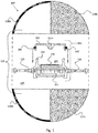
- Fig. 1 shows an exploded view of an embodiment of the measurement device 100 in accordance with the invention.
- the measurement device 100 comprises an external housing 110 having flexible walls 110w.
- the external housing 110 defines (alternatively the words "encloses or isolates" could be used in this context) a first closed volume 105.
- the housing 110 comprises two parts 110a, 110b that are mounted together (through gluing, screwing, clamping, or the like).
- the measurement device 100 further comprises an internal housing 150, which is suspended within the external housing 110 by means of a positioning member 125 as shown.
- the positioning member 125 is preferably also flexible.
- the internal housing 150 comprises a first part 151, which may be non-flexible or at least much less flexible than the external housing 110.
- the first part 151 of the internal housing partially defines a first space 155, which comprises a force sensor 170, which preferably is a force-sensitive resistor (FSR), because of its low power consumption advantage.
- the first space 155 is further sealed off by a flexible membrane 152, which in this embodiment is to be clicked over said first part 151 of the internal housing 150 and held in place with an O-ring 160, as illustrated.
- the membrane 152 in this embodiment is provided with a protruding element 152p, which is advantageous as discussed in the introduction of this specification.
- Fig. 2 shows an enlarged cross-sectional view of the part of the measurement device of Fig. 1 .
- the flexible membrane 152 has been mounted on the first part 151 of the internal housing 150.
- the second closed volume 155 (earlier mentioned first space) is formed. It is illustrated how the flexible membrane 152 faces the first closed volume 105 on a first side 152s1 thereof, and the force sensor 170 on a second, opposite, side 152s2 thereof.
- the figure further illustrates that there is a gap 152d between said protruding part 152p and the force sensor 170.
- Another aspect that Fig. 2 illustrates is the amplification of the pressure/force applied to the membrane 152.
- the pressure in the first closed volume 105 presses on an area 152a with the size as illustrated by the arrow. Under this pressure the membrane 152 may bend towards the force sensor 170. As soon as the protruding element 152p of the membrane touches the force sensor 170 it is the contact area 152pa of the protruding element 152p, as illustrated by the other arrow, which will transfer the force to the force sensor 170. This force/pressure is effectively an amplified version of the force applied to the membrane 152.
- the amplification factor is typically in the order of the ratio between the membrane area 152a and the contact area 152pa of the protruding element 152.
- Fig. 2 further illustrates that the force sensor 170 is connected to a printed-circuit board (PCB) 180 via a connecting wire (or wires) 171.
- the PCB 180 is provided in a second space 181 of the internal housing 150 as illustrated.
- the PCB 180 is provided with en electronic circuit 182 (i.e. an integrated circuit), which may comprise a processor or control unit for controlling and reading out the force sensor 170 and storage circuitry for storing said measurements).
- the electronic circuit 182 in this embodiment also comprises a switching circuit 184 and a communication circuit 186.
- the communication circuit 186 may be a Bluetooth transceiver circuit, which as such is well-known to the person skilled in the art.
- the electronic circuit is power by a battery 190.
- the switching circuit 184 has been added to facilitate deactivating part of the electronic circuit 182, in particular the communication circuit 186, for reasons as earlier discussed, i.e. save power and thereby increase battery lifetime.
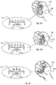
- Figs. 3a-3c illustrate some aspects of the functioning of the measurement device of the invention.
- the hand 200 of the user applies the so-called threshold pressure to the measurement device 100.
- the flexible membrane 152, or the protruding element 152p if present barely touches the force sensor 170, i.e. it begins to apply a small force when the force applied to the measurement device 100 is further increased.
- Fig. 3b shows the situation where the user applies a medium force to the measurement device. In this situation the flexible membrane 152, or the protruding element 152p if present, applies a force to the force sensor 170.
- Fig. 3c shows the situation where the user applies a maximum force to the measurement device. With “maximum force” it is meant the maximum force that can be registered, not the maximum force that could be applied.
- the force sensor 170 in this situation outputs its maximum signal level to the electronic circuit 180.
- Figs. 4a-4d illustrate some other aspects of the functioning of the measurement device of the invention.
- Fig. 4a shows the equilibrium situation, where the user does not apply a pressure to the measurement device 100. Consequently, the membrane 152 applies a zero force F0 to the force sensor 170 (although there is still the pressure in the 155 second closed volume, which applies a pressure on the force sensor 170).
- Fig. 4b shows the situation which complies with Fig. 3a .
- a minimum force Fmn is applied to the force sensor 170.
- Fig. 4c shows the situation that complies with Fig. 3b .
- a medium force Fmd is applied to the force sensor 170.
- Fig. 4d shows the situation that complies with Fig. 3c .
- the maximum registerable force Fmx is applied to the force sensor 170.
- the reason for differentiating between F0 and Fmn is that the force sensor may be very sensitive (for instance when an FSR is used).
- the force sensor may be very sensitive (for instance when an FSR is used).
- the pressure is registered by the measurement device 100.
- the small-signal behaviour in these two situations is very different.
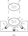
- Figs. 5a-5c illustrate an embodiment of a readout activation system 300 and a readout system for reading out said measurement device in accordance with the invention.
- the communication circuit 182 only needs to be active when the measurement device 100 is read out by a readout system (i.e. laptop, table, PC, smartphone) 400.
- the measurement device 100 may comprise a switching circuit for (triggering) deactivating said communication 182 (and/or other parts).
- the deactivation is done in software.
- the measurement device 100 is configured such, that when it is put in the readout activation device 300 (also called the crib) it will broadcast and be ready for connection for a predefined time, for instance 30 seconds. After this time has lapsed, the measurement device 100 will return to its sleep mode again (arranged in software) even if the measurement device 100 remains in the crib 300.
- the readout activation system 300 which comprises in this embodiment a receiving region 310 (such as a recess) for receiving the measurement device 100 in accordance with the invention.
- a receiving region 310 such as a recess
- the readout activation system 300 is preferably put within Bluetooth communication reach of the readout system 400.
- the measurement device 100 is put into the recess 310.
- the measurement device 100 is activated by the readout activation system 300 and transmits its registered data to the readout system 400 via a wireless communication signal 999 as schematically illustrated.
- the registered data may be shown on the readout system 400 in the form of a graph 410 for example.
- the physician may subsequently interpret the registered data, which forms an indication of the pain, distress or other discomfort of the user over a certain period.
- Fig. 6 illustrates the operation of the readout activation system 300.
- This figure is very schematic in order to facilitate understanding of the principle.
- a plurality (but at least one) of magnets 350 as illustrated. These could be permanent magnets, but also other magnets are possible.
- These magnets 350 generate a magnetic field 355, which subsequently trigger the earlier-discussed switching circuit 184 to activate the communication circuit (not shown in Fig. 6 ), for instance by closing or opening when the measurement device 100 is placed in the recess 310.
- the switching circuit 184 be used to directly switch (on or off) the respective part electronically (i.e. in hardware), but it could also be used to trigger the deactivation through software.
- the measurement device in accordance with the invention is possible without deviating from the scope of protection as defined by the claims. It must be stressed that the protruding element of the membrane is optional, yet results in an advantage when used. In addition, the measurement device may have other forms than illustrated. Furthermore, the second closed volume may be provided outside the first closed volume if so desired, wherein the flexible membrane then effectively forms the interface between both volumes.
Landscapes
- Health & Medical Sciences (AREA)
- Life Sciences & Earth Sciences (AREA)
- Engineering & Computer Science (AREA)
- Physics & Mathematics (AREA)
- Animal Behavior & Ethology (AREA)
- Veterinary Medicine (AREA)
- Biophysics (AREA)
- Pathology (AREA)
- Public Health (AREA)
- Biomedical Technology (AREA)
- Heart & Thoracic Surgery (AREA)
- Medical Informatics (AREA)
- Molecular Biology (AREA)
- Surgery (AREA)
- General Health & Medical Sciences (AREA)
- Psychiatry (AREA)
- Hospice & Palliative Care (AREA)
- Social Psychology (AREA)
- Pain & Pain Management (AREA)
- Child & Adolescent Psychology (AREA)
- Developmental Disabilities (AREA)
- Educational Technology (AREA)
- Psychology (AREA)
- Physiology (AREA)
- Physical Education & Sports Medicine (AREA)
- Dentistry (AREA)
- Oral & Maxillofacial Surgery (AREA)
- General Physics & Mathematics (AREA)
- Computer Networks & Wireless Communication (AREA)
- Measuring And Recording Apparatus For Diagnosis (AREA)
- Measuring Pulse, Heart Rate, Blood Pressure Or Blood Flow (AREA)
Priority Applications (1)
| Application Number | Priority Date | Filing Date | Title |
|---|---|---|---|
| PL17786224T PL3445229T3 (pl) | 2016-04-22 | 2017-04-20 | Urządzenie pomiarowe do wykrywania i pomiaru bólu |
Applications Claiming Priority (2)
| Application Number | Priority Date | Filing Date | Title |
|---|---|---|---|
| NO20160684A NO20160684A1 (en) | 2016-04-22 | 2016-04-22 | Measurement device for detecting and measuring pain |
| PCT/NO2017/050098 WO2017183994A1 (en) | 2016-04-22 | 2017-04-20 | Measurement device for detecting and measuring pain |
Publications (3)
| Publication Number | Publication Date |
|---|---|
| EP3445229A1 EP3445229A1 (en) | 2019-02-27 |
| EP3445229A4 EP3445229A4 (en) | 2019-11-13 |
| EP3445229B1 true EP3445229B1 (en) | 2021-12-15 |
Family
ID=60116211
Family Applications (1)
| Application Number | Title | Priority Date | Filing Date |
|---|---|---|---|
| EP17786224.0A Active EP3445229B1 (en) | 2016-04-22 | 2017-04-20 | Measurement device for detecting and measuring pain |
Country Status (6)
| Country | Link |
|---|---|
| EP (1) | EP3445229B1 (da) |
| DK (1) | DK3445229T3 (da) |
| ES (1) | ES2907947T3 (da) |
| NO (1) | NO20160684A1 (da) |
| PL (1) | PL3445229T3 (da) |
| WO (1) | WO2017183994A1 (da) |
Families Citing this family (3)
| Publication number | Priority date | Publication date | Assignee | Title |
|---|---|---|---|---|
| CA3003155A1 (en) * | 2018-04-25 | 2019-10-25 | Dynamic Disc Designs Corp. | Sensitivity metering system for use in patient diagnosis |
| GB202208551D0 (en) * | 2022-06-10 | 2022-07-27 | Xie Yaqil | Apparatus and method for the assessment of pain |
| WO2023237749A1 (en) | 2022-06-10 | 2023-12-14 | Xie Yaqi | Apparatus and method for the assessment of pain |
Family Cites Families (17)
| Publication number | Priority date | Publication date | Assignee | Title |
|---|---|---|---|---|
| US5157970A (en) * | 1990-10-17 | 1992-10-27 | Lewis Jr Royce C | Grasp analysis method |
| GB9123638D0 (en) * | 1991-11-07 | 1992-01-02 | Magill Alan R | Apparel & fabric & devices suitable for health monitoring applications |
| SE508357C2 (sv) | 1996-01-02 | 1998-09-28 | Kay Laserow | Mätinstrument för mätning av smärta jämte ett förfarande för att med ett mätinstrument mäta smärta |
| US6026684A (en) * | 1998-07-17 | 2000-02-22 | Haemonetics Corporation | Active donor hand gripper for use in a blood collection apparatus |
| US20030009308A1 (en) * | 2000-06-24 | 2003-01-09 | Chris Kirtley | Instrumented insole |
| EP1631222B1 (en) | 2003-05-22 | 2007-01-03 | Medoc Ltd. | Thermal stimulation probe and method |
| US7261106B2 (en) * | 2003-09-25 | 2007-08-28 | Ethicon Endo-Surgery, Inc. | Response testing for conscious sedation utilizing a cannula for support/response |
| US20100228100A1 (en) | 2007-10-15 | 2010-09-09 | Vining David J | Apparatus and method for use in analyzing a patient's bowel |
| FR2936140B1 (fr) * | 2008-09-22 | 2013-01-18 | Univ Troyes Technologie | Dispositif d'evaluation et/ou de renforcement de la force de prehension |
| US20110066078A1 (en) * | 2009-09-14 | 2011-03-17 | Artann Laboratories, Inc. | Pain monitor for a patient undergoing a medical procedure |
| US20110088463A1 (en) * | 2009-10-16 | 2011-04-21 | Shapiro Ronald S | Performance enhancement measurement device for joints |
| EP2515759A4 (en) * | 2009-12-23 | 2015-01-21 | Given Imaging Inc | METHOD OF ASSESSING CONSTIPATION USING INGREDIENT CAPSULE |
| WO2011079966A1 (de) | 2009-12-28 | 2011-07-07 | Msys Ag | Vorrichtung und verfahren zum erfassen und messen von schmerzen |
| AT509443A1 (de) * | 2010-02-12 | 2011-08-15 | Ait Austrian Inst Technology | Verfahren zur objektivierten bestimmung und messung von schmerzen |
| EP2543317B1 (de) * | 2011-07-06 | 2016-10-12 | Msys Ag | Vorrichtung und Verfahren zum Erfassen der Handkraft oder des Handdrucks |
| WO2014151874A1 (en) * | 2013-03-14 | 2014-09-25 | Accendowave Incorporated | Systems, methods and devices for assessing and treating pain, discomfort and anxiety |
| WO2014143675A1 (en) * | 2013-03-15 | 2014-09-18 | Tk Holdings Inc. | Human machine interfaces for pressure sensitive control in a distracted operating environment and method of using the same |
-
2016
- 2016-04-22 NO NO20160684A patent/NO20160684A1/en not_active Application Discontinuation
-
2017
- 2017-04-20 WO PCT/NO2017/050098 patent/WO2017183994A1/en not_active Ceased
- 2017-04-20 EP EP17786224.0A patent/EP3445229B1/en active Active
- 2017-04-20 DK DK17786224.0T patent/DK3445229T3/da active
- 2017-04-20 PL PL17786224T patent/PL3445229T3/pl unknown
- 2017-04-20 ES ES17786224T patent/ES2907947T3/es active Active
Non-Patent Citations (1)
| Title |
|---|
| None * |
Also Published As
| Publication number | Publication date |
|---|---|
| DK3445229T3 (en) | 2022-03-14 |
| EP3445229A4 (en) | 2019-11-13 |
| ES2907947T3 (es) | 2022-04-27 |
| NO20160684A1 (en) | 2017-10-23 |
| PL3445229T3 (pl) | 2022-03-28 |
| EP3445229A1 (en) | 2019-02-27 |
| WO2017183994A1 (en) | 2017-10-26 |
Similar Documents
| Publication | Publication Date | Title |
|---|---|---|
| TWI580233B (zh) | A system with separate computing units | |
| US10987044B2 (en) | Uroflowmetry systems, devices and methods | |
| US9750456B2 (en) | Method and system of attachment and detection of attachment of a wearable sensor to clothing material | |
| US10076251B2 (en) | Physiology signal sensing device | |
| JP5859847B2 (ja) | 液体検知システム | |
| KR102173725B1 (ko) | 생체 신호를 측정하는 방법 및 장치 | |
| EP3445229B1 (en) | Measurement device for detecting and measuring pain | |
| RU2016106344A (ru) | Предмет личной гигиены с цифровым элементом | |
| KR20170008187A (ko) | 스마트 생리컵 및 스마트 생리컵을 이용한 생리혈 측정 방법 | |
| KR20120065540A (ko) | 휴대단말기와 무선 데이터 송수신이 가능한 패치형 센서를 이용한 실시간 건강관리 시스템 | |
| KR200481546Y1 (ko) | 착용형 헬스케어 장치 | |
| US20170224277A1 (en) | Control method of wearable device execution module and wearable device | |
| CN117322860A (zh) | 心率跟踪技术 | |
| EP3189778B1 (en) | Physiological status monitoring device | |
| KR101484026B1 (ko) | 피부 탄성도 측정장치 | |
| US10182761B2 (en) | Method and system of attachment and detection of attachment of a wearable sensor to clothing material | |
| KR101877495B1 (ko) | 스마트 생리컵 및 스마트 생리컵을 이용한 생리혈 측정 방법 | |
| KR20140094912A (ko) | 다중 생체신호 센서 | |
| Islam | Assistive sensing technology for the elderly health monitoring | |
| JP2018050944A (ja) | センサ装置、保険証、会員証 | |
| RU2798240C1 (ru) | Устройство для генерирования аэрозоля, содержащее дисплей (варианты) | |
| KR20240009644A (ko) | 무선 이오닉 리퀴드 압력 센서 | |
| CN106539577A (zh) | 生物信息感测模块及生物信息感测方法 |
Legal Events
| Date | Code | Title | Description |
|---|---|---|---|
| STAA | Information on the status of an ep patent application or granted ep patent |
Free format text: STATUS: THE INTERNATIONAL PUBLICATION HAS BEEN MADE |
|
| PUAI | Public reference made under article 153(3) epc to a published international application that has entered the european phase |
Free format text: ORIGINAL CODE: 0009012 |
|
| STAA | Information on the status of an ep patent application or granted ep patent |
Free format text: STATUS: REQUEST FOR EXAMINATION WAS MADE |
|
| 17P | Request for examination filed |
Effective date: 20181008 |
|
| AK | Designated contracting states |
Kind code of ref document: A1 Designated state(s): AL AT BE BG CH CY CZ DE DK EE ES FI FR GB GR HR HU IE IS IT LI LT LU LV MC MK MT NL NO PL PT RO RS SE SI SK SM TR |
|
| AX | Request for extension of the european patent |
Extension state: BA ME |
|
| DAV | Request for validation of the european patent (deleted) | ||
| DAX | Request for extension of the european patent (deleted) | ||
| A4 | Supplementary search report drawn up and despatched |
Effective date: 20191014 |
|
| RIC1 | Information provided on ipc code assigned before grant |
Ipc: H04B 5/00 20060101ALI20191008BHEP Ipc: H01H 36/00 20060101ALI20191008BHEP Ipc: A61B 5/11 20060101ALI20191008BHEP Ipc: G01L 1/22 20060101ALI20191008BHEP Ipc: A61B 5/00 20060101AFI20191008BHEP Ipc: A61B 5/22 20060101ALI20191008BHEP Ipc: A61B 5/16 20060101ALI20191008BHEP Ipc: G01L 7/06 20060101ALI20191008BHEP Ipc: G01L 9/04 20060101ALI20191008BHEP |
|
| STAA | Information on the status of an ep patent application or granted ep patent |
Free format text: STATUS: EXAMINATION IS IN PROGRESS |
|
| 17Q | First examination report despatched |
Effective date: 20200825 |
|
| GRAP | Despatch of communication of intention to grant a patent |
Free format text: ORIGINAL CODE: EPIDOSNIGR1 |
|
| STAA | Information on the status of an ep patent application or granted ep patent |
Free format text: STATUS: GRANT OF PATENT IS INTENDED |
|
| INTG | Intention to grant announced |
Effective date: 20210927 |
|
| GRAS | Grant fee paid |
Free format text: ORIGINAL CODE: EPIDOSNIGR3 |
|
| GRAA | (expected) grant |
Free format text: ORIGINAL CODE: 0009210 |
|
| STAA | Information on the status of an ep patent application or granted ep patent |
Free format text: STATUS: THE PATENT HAS BEEN GRANTED |
|
| AK | Designated contracting states |
Kind code of ref document: B1 Designated state(s): AL AT BE BG CH CY CZ DE DK EE ES FI FR GB GR HR HU IE IS IT LI LT LU LV MC MK MT NL NO PL PT RO RS SE SI SK SM TR |
|
| REG | Reference to a national code |
Ref country code: GB Ref legal event code: FG4D Ref country code: CH Ref legal event code: EP |
|
| REG | Reference to a national code |
Ref country code: DE Ref legal event code: R096 Ref document number: 602017051000 Country of ref document: DE |
|
| REG | Reference to a national code |
Ref country code: IE Ref legal event code: FG4D |
|
| REG | Reference to a national code |
Ref country code: AT Ref legal event code: REF Ref document number: 1454850 Country of ref document: AT Kind code of ref document: T Effective date: 20220115 |
|
| REG | Reference to a national code |
Ref country code: FI Ref legal event code: FGE Ref country code: DK Ref legal event code: T3 Effective date: 20220307 |
|
| REG | Reference to a national code |
Ref country code: NL Ref legal event code: FP |
|
| REG | Reference to a national code |
Ref country code: SE Ref legal event code: TRGR |
|
| REG | Reference to a national code |
Ref country code: LT Ref legal event code: MG9D |
|
| REG | Reference to a national code |
Ref country code: ES Ref legal event code: FG2A Ref document number: 2907947 Country of ref document: ES Kind code of ref document: T3 Effective date: 20220427 |
|
| PG25 | Lapsed in a contracting state [announced via postgrant information from national office to epo] |
Ref country code: RS Free format text: LAPSE BECAUSE OF FAILURE TO SUBMIT A TRANSLATION OF THE DESCRIPTION OR TO PAY THE FEE WITHIN THE PRESCRIBED TIME-LIMIT Effective date: 20211215 Ref country code: LT Free format text: LAPSE BECAUSE OF FAILURE TO SUBMIT A TRANSLATION OF THE DESCRIPTION OR TO PAY THE FEE WITHIN THE PRESCRIBED TIME-LIMIT Effective date: 20211215 Ref country code: BG Free format text: LAPSE BECAUSE OF FAILURE TO SUBMIT A TRANSLATION OF THE DESCRIPTION OR TO PAY THE FEE WITHIN THE PRESCRIBED TIME-LIMIT Effective date: 20220315 |
|
| REG | Reference to a national code |
Ref country code: NO Ref legal event code: T2 Effective date: 20211215 |
|
| PG25 | Lapsed in a contracting state [announced via postgrant information from national office to epo] |
Ref country code: LV Free format text: LAPSE BECAUSE OF FAILURE TO SUBMIT A TRANSLATION OF THE DESCRIPTION OR TO PAY THE FEE WITHIN THE PRESCRIBED TIME-LIMIT Effective date: 20211215 Ref country code: HR Free format text: LAPSE BECAUSE OF FAILURE TO SUBMIT A TRANSLATION OF THE DESCRIPTION OR TO PAY THE FEE WITHIN THE PRESCRIBED TIME-LIMIT Effective date: 20211215 Ref country code: GR Free format text: LAPSE BECAUSE OF FAILURE TO SUBMIT A TRANSLATION OF THE DESCRIPTION OR TO PAY THE FEE WITHIN THE PRESCRIBED TIME-LIMIT Effective date: 20220316 |
|
| PG25 | Lapsed in a contracting state [announced via postgrant information from national office to epo] |
Ref country code: SM Free format text: LAPSE BECAUSE OF FAILURE TO SUBMIT A TRANSLATION OF THE DESCRIPTION OR TO PAY THE FEE WITHIN THE PRESCRIBED TIME-LIMIT Effective date: 20211215 Ref country code: SK Free format text: LAPSE BECAUSE OF FAILURE TO SUBMIT A TRANSLATION OF THE DESCRIPTION OR TO PAY THE FEE WITHIN THE PRESCRIBED TIME-LIMIT Effective date: 20211215 Ref country code: RO Free format text: LAPSE BECAUSE OF FAILURE TO SUBMIT A TRANSLATION OF THE DESCRIPTION OR TO PAY THE FEE WITHIN THE PRESCRIBED TIME-LIMIT Effective date: 20211215 Ref country code: PT Free format text: LAPSE BECAUSE OF FAILURE TO SUBMIT A TRANSLATION OF THE DESCRIPTION OR TO PAY THE FEE WITHIN THE PRESCRIBED TIME-LIMIT Effective date: 20220418 Ref country code: EE Free format text: LAPSE BECAUSE OF FAILURE TO SUBMIT A TRANSLATION OF THE DESCRIPTION OR TO PAY THE FEE WITHIN THE PRESCRIBED TIME-LIMIT Effective date: 20211215 Ref country code: CZ Free format text: LAPSE BECAUSE OF FAILURE TO SUBMIT A TRANSLATION OF THE DESCRIPTION OR TO PAY THE FEE WITHIN THE PRESCRIBED TIME-LIMIT Effective date: 20211215 |
|
| REG | Reference to a national code |
Ref country code: DE Ref legal event code: R097 Ref document number: 602017051000 Country of ref document: DE |
|
| PLBE | No opposition filed within time limit |
Free format text: ORIGINAL CODE: 0009261 |
|
| STAA | Information on the status of an ep patent application or granted ep patent |
Free format text: STATUS: NO OPPOSITION FILED WITHIN TIME LIMIT |
|
| PG25 | Lapsed in a contracting state [announced via postgrant information from national office to epo] |
Ref country code: AL Free format text: LAPSE BECAUSE OF FAILURE TO SUBMIT A TRANSLATION OF THE DESCRIPTION OR TO PAY THE FEE WITHIN THE PRESCRIBED TIME-LIMIT Effective date: 20211215 |
|
| 26N | No opposition filed |
Effective date: 20220916 |
|
| PG25 | Lapsed in a contracting state [announced via postgrant information from national office to epo] |
Ref country code: SI Free format text: LAPSE BECAUSE OF FAILURE TO SUBMIT A TRANSLATION OF THE DESCRIPTION OR TO PAY THE FEE WITHIN THE PRESCRIBED TIME-LIMIT Effective date: 20211215 |
|
| PG25 | Lapsed in a contracting state [announced via postgrant information from national office to epo] |
Ref country code: MC Free format text: LAPSE BECAUSE OF FAILURE TO SUBMIT A TRANSLATION OF THE DESCRIPTION OR TO PAY THE FEE WITHIN THE PRESCRIBED TIME-LIMIT Effective date: 20211215 Ref country code: LU Free format text: LAPSE BECAUSE OF NON-PAYMENT OF DUE FEES Effective date: 20220420 |
|
| P01 | Opt-out of the competence of the unified patent court (upc) registered |
Effective date: 20230524 |
|
| REG | Reference to a national code |
Ref country code: AT Ref legal event code: UEP Ref document number: 1454850 Country of ref document: AT Kind code of ref document: T Effective date: 20211215 |
|
| PG25 | Lapsed in a contracting state [announced via postgrant information from national office to epo] |
Ref country code: HU Free format text: LAPSE BECAUSE OF FAILURE TO SUBMIT A TRANSLATION OF THE DESCRIPTION OR TO PAY THE FEE WITHIN THE PRESCRIBED TIME-LIMIT; INVALID AB INITIO Effective date: 20170420 |
|
| PG25 | Lapsed in a contracting state [announced via postgrant information from national office to epo] |
Ref country code: MK Free format text: LAPSE BECAUSE OF FAILURE TO SUBMIT A TRANSLATION OF THE DESCRIPTION OR TO PAY THE FEE WITHIN THE PRESCRIBED TIME-LIMIT Effective date: 20211215 Ref country code: CY Free format text: LAPSE BECAUSE OF FAILURE TO SUBMIT A TRANSLATION OF THE DESCRIPTION OR TO PAY THE FEE WITHIN THE PRESCRIBED TIME-LIMIT Effective date: 20211215 |
|
| PG25 | Lapsed in a contracting state [announced via postgrant information from national office to epo] |
Ref country code: MT Free format text: LAPSE BECAUSE OF FAILURE TO SUBMIT A TRANSLATION OF THE DESCRIPTION OR TO PAY THE FEE WITHIN THE PRESCRIBED TIME-LIMIT Effective date: 20211215 |
|
| PGFP | Annual fee paid to national office [announced via postgrant information from national office to epo] |
Ref country code: IS Payment date: 20250324 Year of fee payment: 9 |
|
| PGFP | Annual fee paid to national office [announced via postgrant information from national office to epo] |
Ref country code: NO Payment date: 20250318 Year of fee payment: 9 |
|
| PGFP | Annual fee paid to national office [announced via postgrant information from national office to epo] |
Ref country code: NL Payment date: 20250422 Year of fee payment: 9 |
|
| PGFP | Annual fee paid to national office [announced via postgrant information from national office to epo] |
Ref country code: FI Payment date: 20250410 Year of fee payment: 9 |
|
| PGFP | Annual fee paid to national office [announced via postgrant information from national office to epo] |
Ref country code: DE Payment date: 20250403 Year of fee payment: 9 |
|
| PGFP | Annual fee paid to national office [announced via postgrant information from national office to epo] |
Ref country code: DK Payment date: 20250401 Year of fee payment: 9 Ref country code: GB Payment date: 20250404 Year of fee payment: 9 Ref country code: ES Payment date: 20250502 Year of fee payment: 9 |
|
| PGFP | Annual fee paid to national office [announced via postgrant information from national office to epo] |
Ref country code: BE Payment date: 20250409 Year of fee payment: 9 Ref country code: IT Payment date: 20250416 Year of fee payment: 9 |
|
| PGFP | Annual fee paid to national office [announced via postgrant information from national office to epo] |
Ref country code: FR Payment date: 20250404 Year of fee payment: 9 |
|
| PGFP | Annual fee paid to national office [announced via postgrant information from national office to epo] |
Ref country code: CH Payment date: 20250501 Year of fee payment: 9 |
|
| PGFP | Annual fee paid to national office [announced via postgrant information from national office to epo] |
Ref country code: AT Payment date: 20250424 Year of fee payment: 9 |
|
| PGFP | Annual fee paid to national office [announced via postgrant information from national office to epo] |
Ref country code: IE Payment date: 20250404 Year of fee payment: 9 |
|
| PGFP | Annual fee paid to national office [announced via postgrant information from national office to epo] |
Ref country code: SE Payment date: 20250401 Year of fee payment: 9 |
|
| PG25 | Lapsed in a contracting state [announced via postgrant information from national office to epo] |
Ref country code: TR Free format text: LAPSE BECAUSE OF FAILURE TO SUBMIT A TRANSLATION OF THE DESCRIPTION OR TO PAY THE FEE WITHIN THE PRESCRIBED TIME-LIMIT Effective date: 20211215 |
|
| PGFP | Annual fee paid to national office [announced via postgrant information from national office to epo] |
Ref country code: PL Payment date: 20260323 Year of fee payment: 10 |