EP3445593B1 - Stylo marqueur à régulation de pression interne - Google Patents
Stylo marqueur à régulation de pression interne Download PDFInfo
- Publication number
- EP3445593B1 EP3445593B1 EP17786447.7A EP17786447A EP3445593B1 EP 3445593 B1 EP3445593 B1 EP 3445593B1 EP 17786447 A EP17786447 A EP 17786447A EP 3445593 B1 EP3445593 B1 EP 3445593B1
- Authority
- EP
- European Patent Office
- Prior art keywords
- cavity
- piston
- pressure
- writing implement
- nib
- Prior art date
- Legal status (The legal status is an assumption and is not a legal conclusion. Google has not performed a legal analysis and makes no representation as to the accuracy of the status listed.)
- Active
Links
Images


Classifications
-
- B—PERFORMING OPERATIONS; TRANSPORTING
- B43—WRITING OR DRAWING IMPLEMENTS; BUREAU ACCESSORIES
- B43K—IMPLEMENTS FOR WRITING OR DRAWING
- B43K5/00—Pens with ink reservoirs in holders, e.g. fountain-pens
- B43K5/02—Ink reservoirs
- B43K5/06—Ink reservoirs with movable pistons for withdrawing ink from an ink-receptacle
-
- B—PERFORMING OPERATIONS; TRANSPORTING
- B43—WRITING OR DRAWING IMPLEMENTS; BUREAU ACCESSORIES
- B43K—IMPLEMENTS FOR WRITING OR DRAWING
- B43K8/00—Pens with writing-points other than nibs or balls
- B43K8/02—Pens with writing-points other than nibs or balls with writing-points comprising fibres, felt, or similar porous or capillary material
-
- B—PERFORMING OPERATIONS; TRANSPORTING
- B43—WRITING OR DRAWING IMPLEMENTS; BUREAU ACCESSORIES
- B43K—IMPLEMENTS FOR WRITING OR DRAWING
- B43K23/00—Holders or connectors for writing implements; Means for protecting the writing-points
- B43K23/08—Protecting means, e.g. caps
-
- B—PERFORMING OPERATIONS; TRANSPORTING
- B43—WRITING OR DRAWING IMPLEMENTS; BUREAU ACCESSORIES
- B43K—IMPLEMENTS FOR WRITING OR DRAWING
- B43K8/00—Pens with writing-points other than nibs or balls
- B43K8/02—Pens with writing-points other than nibs or balls with writing-points comprising fibres, felt, or similar porous or capillary material
- B43K8/04—Arrangements for feeding ink to writing-points
Definitions
- the present invention relates to a writing implement, a method of manufacturing a writing implement and more particularly to regulating an internal pressure within a writing implement.
- a marker pen typically includes a body having a first end and a second end. The first end is coupled to a nib (e.g., tip) and the second end is an impermeable end cap that is fixed to the body.
- the body also defines a cavity having a fixed volume between the first end and the second end to hold a writing material (e.g., ink, paint, etc.).
- the nib is used to dispense the writing material from the cavity and onto a work surface.
- US 6102601 A describes an ink chamber pressure enhancing control device.
- the device includes a valve block mounted in a barrel of a writing instrument above an ink chamber, a cap axially movably mounted in the valve block above a valve port in the valve block, and a piston supported on a spring member above the ink chamber in the barrel.
- the piston is forced upwards by the spring member to close the valve port, enabling an air chamber to be formed within the cap and the valve block above the valve port. Air is forced into the ink chamber in the writing instrument when the cap is depressed.
- WO 01/65970 A1 describes a pressurised writing device comprising an ink tube having a first end and second end. A writing tip is provided at the first end and an end plug at the second end. A pressurizing system applies a force to a writing medium in the ink tube to force the writing medium out the writing tip.
- the pressurization system includes a compressible ink driving member.
- EP 2933117 A1 describes a writing instrument in which a flow pressure of an ink applied to a pen tip is controlled to a fixed level to prevent an ink direct flow phenomenon-reverse flow phenomenon.
- EP 2933117 A1 describes a writing instrument comprising a pen tip disposed at a front part of an ink tank, an ink received in the ink tank, a follower filled at a rear part of the ink, and a capillary porous member provided with a capillary force.
- the invention relates to a writing implement, as defined in claim 1 and configured to dispense material onto a work surface.
- the writing implement includes a body having a first end, a second end, and an inner surface.
- the writing implement also includes a nib coupled to the first end.
- the nib is configured to allow the material to be dispensed onto the work piece.
- the writing implement further includes a piston coupled to the body.
- the piston and the inner surface define a cavity configured to hold the material.
- the piston is moveable relative to the body in response to a pressure change within the cavity.
- the piston is coupled within the body and has a first surface that faces the first end and a second surface that faces the second end.
- the cavity is configured to hold the material between the first surface and the nib.
- the piston includes a groove positioned between the first surface and the second surface. The groove is sized to receive a seal. At least one of the piston and the seal slidably engages the inner surface of the body.
- the invention in another aspect, relates to a method of manufacturing a writing implement, as defined in claim 9, and including providing a body having a first end, a second end, and an inner surface.
- the method also includes inserting a piston through the second end of the body to define a cavity between the inner surface of the body and the piston.
- the piston is configured to be moveable relative to the body to control a pressure within the cavity.
- the method further includes injecting a material through the first end of the body into the cavity and coupling a nib to the first end of the body.
- the nib is configured to allow the material to be dispensed onto a work surface.
- the piston is coupled within the body and has a first surface that faces the first end and a second surface that faces the second end.
- the cavity is configured to hold the material between the first surface and the nib.
- the piston includes a groove positioned between the first surface and the second surface. The groove is sized to receive a seal. At least one of the piston and the seal slidably engages the inner surface of the body.
- FIGS. 1 and 2 illustrate a marker pen 10 (e.g., a permanent marker, writing implement, etc.) including a body 14 having a first end 18 and a second end 22.
- a cap 26 is removably coupled to the first end 18 for covering and protecting the first end 18 of the marker 10.
- the body 14 includes an inner surface 24 that defines an internal diameter 28.
- the inner surface 24 also defines an internal cavity 30 of the body 14.
- the cavity 30 is in fluid communication with a tip or nib 34 that is coupled to the first end 18.
- a portion of the cavity 30 contains a liquid writing material or solution 38 (e.g., ink, etc.) that is configured to flow through the nib 34 to be transferred to a work surface.
- a liquid writing material or solution 38 e.g., ink, etc.
- the liquid solution 38 is a permanent writing solution (e.g., paint solution and/or a metallic solution, etc.). In other embodiments, the liquid solution 38 may be a highlighter or fluorescent solution. In further embodiments, the liquid solution 38 may be a removable or washable solution (e.g., non-permanent).
- a pressure regulating assembly 40 includes a plug or end cap 42 that is coupled to the second end 22 of the marker 10 and a piston 46 slidably received within the cavity 30 between the plug 42 and the liquid solution 38.
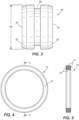
- the illustrated piston 46 defines a solid cylindrical member including a first surface 50 that faces the liquid solution 38, a second surface 54 that faces the plug 42, a groove 58 positioned between the surfaces 50, 54, and a chamfer 62 located between the groove 58 and the first surface 50 as well as between the groove 58 and the second surface 54 ( FIG. 3 ).
- the piston 46 can be a hollow cylindrical member.
- the piston 46 includes an outer diameter 66 ( FIG.
- the seal 70 receives a seal 70 that directly contacts the inner surface 24 of the body 14.
- the seal 70 and the piston 46 directly contact the inner surface 24.
- the seal 70 includes four arcuate or concave sides 74 (e.g., a quad-ring or X-ring).
- the seal 70 may include a circular cross section (e.g., an O-ring), an ellipse cross section, a square cross section, a rectangular cross section, etc.
- the illustrated plug 42 is configured to provide communication between the cavity 30 and the ambient air surrounding the marker 10 and to inhibit dust and debris from entering the cavity 30.
- the plug 42 allows air to pass therethrough to either exit or enter the cavity 30 (e.g., between the second surface 54 and the plug 42).
- the plug 42 may be an absorbent or porous cylindrical member.
- the seal 70 is coupled to the piston within the groove 58 so that the piston 46 and the seal 70 are both inserted into the body 14 through the second end 22.
- the piston 46 and the seal 70 are positioned within the cavity 30 at a desired location relative to the second end 22 to define a desired volume of the cavity 30 between the first surface 50 of the piston 46 and the first end 18 ( FIG. 2 ).
- the body 14 is oriented in an upright position (e.g., the first end 18 is above the second end 22)
- the liquid solution 38 is injected through the first end 18 and into the cavity 30 (e.g., into the volume defined between the first surface 50 and the first end 18).
- the piston 46 may be temporality fixed relative to the body 14 while the cavity 30 is filled with the liquid solution 38. Once a determined amount of the liquid solution 38 is injected into the cavity 30, the nib 34 is coupled to the first end 18.
- the plug 42 is coupled to the second end 22.
- the piston 46 and seal 70 are sized and configured to inhibit the liquid solution 38 from traveling between the piston 46 and the plug 42. In other words, only ambient air is located between the piston 46 and the plug 42.
- the piston 46 is inserted into the body 14 at the desired location so that a desired internal pressure 78 (e.g., ambient pressure surrounding the marker 10) within the cavity 30 is created once the liquid solution 38 is injected into the cavity 30 and the nib 34 is coupled to the first end 18.
- a desired internal pressure 78 e.g., ambient pressure surrounding the marker 10.
- the desired internal pressure 78 is substantially maintained by the frictional engagement between the piston 46 and/or the seal 70 against the inner surface 24 of the body 14.
- the desired internal pressure 78 may be slightly greater than the ambient pressure surrounding the marker 10.
- the nib 34 is depressed against the work surface to allow the liquid solution 38 to travel from the cavity 30 through the nib 34 to be dispensed onto the work piece (e.g., fluid communication between the cavity 30 and the ambient environment is provided by depressing the nib 34 onto the work surface). Once the nib 34 is moved out of contact with the work surface, the nib 34 blocks the liquid solution 38 from traveling from the cavity 30 through the nib 34 and onto the work surface (e.g., fluid communication between the cavity 30 and the ambient environment is blocked by the nib 34).
- the pressure within the cavity 30 may increase or decrease upon either expansion or contraction of the liquid solution 38.
- an actual pressure 80 FIG. 6
- the desired internal pressure 78 e.g., a positive pressure change. If the higher actual pressure 80 is maintained within the marker 10, more liquid solution 38 than is desired will initially exit the nib 34 once the nib 34 is depressed onto the work surface (e.g., the higher actual pressure 80 will push out an undesirable amount of liquid solution 38 onto the work surface).
- the illustrated pressure regulating assembly 40 regulates (e.g., controls) the actual pressure 80 within the cavity 30 relative to the desired internal pressure 78 before the nib 34 is depressed onto the work surface.
- the higher actual pressure 80 within the cavity 30 will act against the first surface 50 of the piston 46 to move the piston 46 towards the plug 42, thereby increasing a volume of the cavity 30 between the nib 34 and the first surface 50.
- the actual pressure 80 within the cavity 30 decreases to be substantially equal with the desired internal pressure 78.
- the piston 46 moves towards the plug 42, the piston 46 pushes the ambient air positioned between the second surface 54 and the plug 42 through the plug 42 and into the ambient environment.
- a constant and desired flow of liquid solution 38 travels through the nib 34 once the nib 34 is depressed onto the work surface regardless of the orientation of the marker 10 (e.g., using the marker 10 upside down).
- the actual pressure 80 within the cavity 30 will also decrease below the determined internal pressure 78 (e.g., a negative pressure change). As such, the lower actual pressure 80 within the cavity 30 will move the piston 46 towards the first end 18 to again substantially equalize the actual pressure 80 with the desired internal pressure 78.
- the determined internal pressure 78 e.g., a negative pressure change
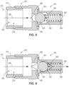
- FIGS. 8 and 9 illustrate a portion of a marker 210 according to another embodiment of the invention.
- the marker 210 is similar to the marker 10 with similar components including similar reference numbers incremented by 200. Only the differences between the markers 10, 210 will be described below in detail. In addition, components or features described with respect to only one or some of the embodiments described herein are equally applicable to any other embodiments described herein.
- the illustrated marker 210 includes a pressure regulating assembly 240 coupled to a second end 222 of a body 214 and is in communication with a cavity 230 defined by the body 214.
- the pressure regulating assembly 240 includes a body 242 having an inlet 286 and an outlet 290 with a valve 294 (e.g., a ball valve, etc.) and a biasing member 298 (e.g., a coil spring, etc.) located between the inlet and outlet 286, 290.
- the valve 294 is positioned between a first edge 300 of the inlet 286 and a tapered surface or second edge 302 defined on an inner surface of the body 242.
- the tapered surface 302 is positioned between the edge 300 and the outlet 290.
- the biasing member 298 provides a biasing force against the valve 294 towards the inlet 286 thereby creating a biasing pressure 306 of the valve 294 acting on the first edge 300.
- the illustrated biasing pressure 306 is a determined pressure.
- the combination of the valve 294 and the biasing member 298 is commonly referenced as a check valve.
- the valve 294 and/or the biasing member 298 may be positioned between the inlet 286 and the cavity 230.
- the biasing member 298 forces the valve 294 into engagement with the first edge 300 when an actual internal pressure 280 within the cavity 230 is less than the biasing pressure 306 ( FIG. 8 ). As such, communication between the cavity 230 and the outlet 290 is blocked by the valve 294 engaging the first edge 300 of the body 242.
- the internal pressure 280 acts on the valve 294 to move the valve 294 towards the outlet 290.
- the internal pressure 280 is allowed to flow around the valve 294 and exit the marker 210 through the outlet 290.
- the internal pressure 280 can push the valve 294 into engagement with the tapered surface 302. In this situation, the internal pressure 280 within the cavity 230 is still allowed to escape through the outlet 290 (e.g., engagement between the valve 294 and the tapered surface 302 does not block communication between the cavity 230 and the outlet 290).
- the internal pressure 280 will continue to exit the outlet 290 (e.g., the internal pressure 280 within the cavity 230 will decrease) until the internal pressure 280 substantially equalizes with a desired internal pressure 278 of the cavity 230. Thereafter, the biasing member 298 pushes the valve 294 back into engagement with the first edge 300 to block fluid communication between the cavity 230 and the outlet 290.
- the pressure regulating assembly 240 can include a filter positioned between the cavity 230 and the inlet 286 to inhibit a liquid solution from traveling past the inlet 286 but allows air to travel past the inlet 286 and toward the outlet 290.
Landscapes
- Engineering & Computer Science (AREA)
- Mechanical Engineering (AREA)
- Pens And Brushes (AREA)
Claims (10)
- Article d'écriture (10) configuré pour distribuer un matériau (38) sur une surface de travail, l'article d'écriture (10) comprenant :un corps (14) comprenant une première extrémité (18), une seconde extrémité (22) et une surface intérieure (24) ;une pointe (34) couplée à la première extrémité (18), la pointe (34) étant configurée pour permettre au matériau (38) d'être distribué sur la surface de travail ;un capuchon d'extrémité poreux absorbant (42) couplé à la seconde extrémité (22) et configuré pour permettre à l'air ambiant de passer à travers le capuchon d'extrémité poreux absorbant (42) ; etun piston (46) couplé au corps (14), le piston (46) et la surface intérieure (24) définissant une cavité (30) configurée pour retenir le matériau (38), le piston (46) étant mobile par rapport au corps (14) en réponse à un changement de température qui change une pression à l'intérieur de la cavité (30),dans lequel le piston (46) est couplé à l'intérieur du corps (14), le piston (46) ayant une première surface (50) qui fait face à la première extrémité (18) et une seconde surface (54) qui fait face à la seconde extrémité (22), et dans lequel la cavité (30) est configurée pour retenir le matériau (38) entre la première surface (50) et la pointe (34),et dans lequel le piston (46) comprend une rainure (58) positionnée entre la première surface (50) et la seconde surface (54), et dans lequel la rainure est dimensionnée pour recevoir un joint (70), et dans lequel au moins un élément parmi le piston (46) et le joint (70) vient en prise de manière coulissante avec la surface intérieure (24) du corps (14).
- Article d'écriture (10) selon la revendication 1, dans lequel le piston (46) et la surface intérieure (24) sont configurés pour retenir le matériau (38) à une pression souhaitée, le piston (46) étant mobile par rapport au corps (14) pour contrôler une pression réelle à l'intérieur de la cavité (30) par rapport à la pression souhaitée.
- Article d'écriture (10) selon la revendication 1, dans lequel un volume de la cavité (30) augmente lorsque le piston (46) se déplace vers la seconde extrémité (22) en réponse à la pression à l'intérieur de la cavité (30) augmentant au-dessus d'une pression souhaitée à l'intérieur de la cavité (30) ; ou article d'écriture (10) selon la revendication 2, dans lequel un volume de la cavité (30) augmente lorsque le piston (46) se déplace vers la seconde extrémité (22) en réponse à la pression réelle à l'intérieur de la cavité (30) augmentant au-dessus de la pression souhaitée à l'intérieur de la cavité (30) .
- Article d'écriture (10) selon la revendication 3 telle qu'elle dépend de la revendication 1, dans lequel le volume de la cavité (30) diminue lorsque le piston (46) se déplace vers la première extrémité (18) en réponse à la pression à l'intérieur de la cavité (30) diminuant en-dessous de la pression souhaitée à l'intérieur de la cavité (30).
- Article d'écriture (10) selon la revendication 1, dans lequel le capuchon d'extrémité poreux absorbant (42) est couplé à la seconde extrémité (22) de sorte que le piston (46) soit couplé entre le capuchon d'extrémité poreux absorbant (42) et la pointe (34), et dans lequel le capuchon d'extrémité poreux absorbant (42) est configuré pour permettre à l'air ambiant de passer à travers le capuchon d'extrémité poreux absorbant (42) .
- Article d'écriture (10) selon la revendication 1 ou la revendication 2, comprenant en outre un clapet anti-retour couplé à la seconde extrémité (22) du corps (14).
- Article d'écriture (10) selon la revendication 6, telle qu'elle dépend de la revendication 1, dans lequel le clapet anti-retour comprend un corps de clapet anti-retour (242) ayant une entrée (286), une sortie (290), un clapet (294) et un élément de sollicitation (298), et dans lequel le clapet (294) et l'élément de sollicitation (298) sont positionnés entre l'entrée (286) et la sortie (290), et dans lequel l'élément de sollicitation (298) est configuré pour solliciter le clapet (294) en mise en prise avec un premier bord (300) de l'entrée (286) pour empêcher la pression à l'intérieur de la cavité (30) de sortir de la sortie (290) ; ou
article d'écriture (10) selon la revendication 6, telle qu'elle dépend de la revendication 2, dans lequel le clapet anti-retour comprend un corps de clapet anti-retour (242) ayant une entrée (286), une sortie (290), un clapet (294) et un élément de sollicitation (298), et dans lequel le clapet (294) et l'élément de sollicitation (298) sont positionnés entre l'entrée (286) et la sortie (290), et dans lequel l'élément de sollicitation (298) est configuré pour solliciter le clapet (294) en mise en prise avec un premier bord (300) de l'entrée (286) pour empêcher la pression réelle à l'intérieur de la cavité (30) de sortir de la sortie (290). - Article d'écriture (10) selon la revendication 7, telle qu'elle dépend de la revendication 1 à la revendication 6, dans lequel le clapet (294) est mobile vers la sortie (290) pour permettre à la pression à l'intérieur de la cavité (30) de sortir de la sortie (290) en réponse à la pression à l'intérieur de la cavité (30) augmentant au-dessus d'une pression souhaitée à l'intérieur de la cavité (30) ; ou article d'écriture (10) selon la revendication 7, telle qu'elle dépend de la revendication 2 à la revendication 6, dans lequel le clapet (294) est mobile vers la sortie (290) pour permettre à la pression réelle à l'intérieur de la cavité (30) de sortir de la sortie (290) en réponse à la pression réelle à l'intérieur de la cavité (30) augmentant au-dessus de la pression souhaitée à l'intérieur de la cavité (30).
- Procédé de fabrication d'un article d'écriture (10), le procédé consistant à :fournir un corps (14) comprenant une première extrémité (18), une seconde extrémité (22) et une surface intérieure (24) ;insérer un piston (46) à travers la seconde extrémité (22) du corps (14) pour définir une cavité (30) entre la surface intérieure (24) du corps (14) et le piston (46), le piston (46) étant configuré pour être mobile par rapport au corps (14) pour contrôler une pression à l'intérieur de la cavité (30) ;coupler un capuchon d'extrémité poreux absorbant (42) à la seconde extrémité (22) qui permet à l'air ambiant de passer à travers le capuchon d'extrémité poreux absorbant (42) ;injecter un matériau (38) à travers la première extrémité (18) du corps (14) dans la cavité (30) ; etcoupler une pointe (34) à la première extrémité (18) du corps (14), la pointe (34) étant configurée pour permettre au matériau (38) d'être distribué sur une surface de travail,dans lequel le piston (46) est couplé à l'intérieur du corps (14), le piston (46) ayant une première surface (50) qui fait face à la première extrémité (18) et une seconde surface (54) qui fait face à la seconde extrémité (22), et dans lequel la cavité (30) est configurée pour retenir le matériau (38) entre la première surface (50) et la pointe (34),et dans lequel le piston (46) comprend une rainure (58) positionnée entre la première surface (50) et la seconde surface (54), et dans lequel la rainure est dimensionnée pour recevoir un joint (70), et dans lequel au moins un élément parmi le piston (46) et le joint (70) vient en prise de manière coulissante avec la surface intérieure (24) du corps (14).
- Procédé selon la revendication 9, dans lequel le piston (46) est positionné entre le capuchon d'extrémité poreux absorbant (42) et la pointe (34).
Applications Claiming Priority (2)
| Application Number | Priority Date | Filing Date | Title |
|---|---|---|---|
| US201662325512P | 2016-04-21 | 2016-04-21 | |
| PCT/US2017/028074 WO2017184570A1 (fr) | 2016-04-21 | 2017-04-18 | Stylo marqueur à régulation de pression interne |
Publications (3)
| Publication Number | Publication Date |
|---|---|
| EP3445593A1 EP3445593A1 (fr) | 2019-02-27 |
| EP3445593A4 EP3445593A4 (fr) | 2019-11-20 |
| EP3445593B1 true EP3445593B1 (fr) | 2024-07-17 |
Family
ID=60089366
Family Applications (1)
| Application Number | Title | Priority Date | Filing Date |
|---|---|---|---|
| EP17786447.7A Active EP3445593B1 (fr) | 2016-04-21 | 2017-04-18 | Stylo marqueur à régulation de pression interne |
Country Status (5)
| Country | Link |
|---|---|
| US (4) | US10603947B2 (fr) |
| EP (1) | EP3445593B1 (fr) |
| CN (2) | CN109070623B (fr) |
| TW (1) | TWM549710U (fr) |
| WO (1) | WO2017184570A1 (fr) |
Families Citing this family (2)
| Publication number | Priority date | Publication date | Assignee | Title |
|---|---|---|---|---|
| USD875177S1 (en) * | 2018-06-12 | 2020-02-11 | Chongbiao Zhao | Pen |
| CN115742605A (zh) * | 2022-10-27 | 2023-03-07 | 西北工业大学宁波研究院 | 一种太空出舱笔笔芯 |
Citations (2)
| Publication number | Priority date | Publication date | Assignee | Title |
|---|---|---|---|---|
| US2294596A (en) * | 1940-08-06 | 1942-09-01 | Dole Kenneth | Fountain pen |
| EP2933117A1 (fr) * | 2012-12-04 | 2015-10-21 | Mitsubishi Pencil Company, Limited | Instrument d'écriture |
Family Cites Families (27)
| Publication number | Priority date | Publication date | Assignee | Title |
|---|---|---|---|---|
| US1065872A (en) * | 1912-11-21 | 1913-06-24 | Samuel Insull | Fountain-pen. |
| US1457875A (en) * | 1922-09-26 | 1923-06-05 | Noel H Coates | Stylographic fountain pen |
| GB688891A (en) * | 1946-05-13 | 1953-03-18 | Compania Uruguaya De Fomento Industrial Sa | Improvements in and relating to reservoir writing instruments |
| US2954264A (en) * | 1957-03-04 | 1960-09-27 | A P D Co | Sealing ring |
| US3397939A (en) * | 1966-09-14 | 1968-08-20 | Carter S Ink Co | Marking instrument |
| US3622168A (en) * | 1970-07-16 | 1971-11-23 | George V Woodling | Rotary shaft seal means |
| DE3772608D1 (de) * | 1986-04-10 | 1991-10-10 | Jiro Hori | Geraet, zum beispiel schreibstift, zum aufbringen von fluessigkeit. |
| JPH0433804Y2 (fr) * | 1986-10-29 | 1992-08-12 | ||
| DE69125774T2 (de) * | 1990-09-11 | 1997-07-31 | Jiro Hori | Markierer |
| JPH04332698A (ja) * | 1991-05-08 | 1992-11-19 | Jiro Hori | 直液形筆記具のスライド栓 |
| JP2679918B2 (ja) * | 1992-02-17 | 1997-11-19 | 二郎 堀 | 筆記具 |
| US5607766A (en) * | 1993-03-30 | 1997-03-04 | American Filtrona Corporation | Polyethylene terephthalate sheath/thermoplastic polymer core bicomponent fibers, method of making same and products formed therefrom |
| US5344670A (en) * | 1993-07-22 | 1994-09-06 | Sierra Innotek, Inc. | System for applying chemiluminescent fluid to an object |
| US5924810A (en) * | 1997-11-05 | 1999-07-20 | Bic Corporation | Double seal system for pressurized writing device |
| US6102601A (en) * | 1999-03-30 | 2000-08-15 | Pro Eton Corporation | Ink chamber pressure enhancing control |
| JP2001138689A (ja) * | 1999-11-12 | 2001-05-22 | Sailor Pen Co Ltd:The | 塗布具 |
| US6361234B1 (en) | 2000-03-08 | 2002-03-26 | Bic Corporation | Pressurized writing instrument employing a compressible piston member |
| JP3436728B2 (ja) * | 2000-05-08 | 2003-08-18 | 株式会社 ヒックス | 筆記具 |
| DE102004053083A1 (de) * | 2004-02-09 | 2005-09-01 | Ludwig Ehrhardt Gmbh | Abstreif- und/oder Dichtungselement sowie Verfahren zum Abdichten eines Kolbens und Spann-und/oder Stützelement |
| US20060013636A1 (en) * | 2004-07-15 | 2006-01-19 | Shachar Shalom | Pen |
| JP2007152745A (ja) * | 2005-12-05 | 2007-06-21 | Tombow Pencil Co Ltd | 加圧ペン |
| JP4137963B2 (ja) | 2006-09-08 | 2008-08-20 | 三菱鉛筆株式会社 | 筆記具 |
| CN201176060Y (zh) * | 2008-03-28 | 2009-01-07 | 徐春华 | 一种记号笔 |
| CN201509801U (zh) * | 2009-09-30 | 2010-06-23 | 许作明 | 一种气压驱动推送料的笔 |
| CN201895480U (zh) * | 2009-10-21 | 2011-07-13 | 上海白金制笔有限公司 | 一种直液式笔 |
| US8092108B2 (en) * | 2009-12-30 | 2012-01-10 | Harry Bainbridge | Porous tip liquid applicator having draw fill mechanism |
| CN205033777U (zh) * | 2015-10-10 | 2016-02-17 | 王君豪 | 一种多功能笔 |
-
2017
- 2017-04-18 EP EP17786447.7A patent/EP3445593B1/fr active Active
- 2017-04-18 US US15/490,171 patent/US10603947B2/en not_active Expired - Fee Related
- 2017-04-18 CN CN201780024157.XA patent/CN109070623B/zh active Active
- 2017-04-18 WO PCT/US2017/028074 patent/WO2017184570A1/fr not_active Ceased
- 2017-04-18 CN CN202110851128.9A patent/CN113580810B/zh active Active
- 2017-04-20 TW TW106205482U patent/TWM549710U/zh not_active IP Right Cessation
-
2020
- 2020-02-18 US US16/793,885 patent/US11148461B2/en active Active
-
2021
- 2021-09-29 US US17/489,165 patent/US11524517B2/en active Active
-
2022
- 2022-12-06 US US18/062,401 patent/US11964510B2/en active Active
Patent Citations (2)
| Publication number | Priority date | Publication date | Assignee | Title |
|---|---|---|---|---|
| US2294596A (en) * | 1940-08-06 | 1942-09-01 | Dole Kenneth | Fountain pen |
| EP2933117A1 (fr) * | 2012-12-04 | 2015-10-21 | Mitsubishi Pencil Company, Limited | Instrument d'écriture |
Also Published As
| Publication number | Publication date |
|---|---|
| EP3445593A1 (fr) | 2019-02-27 |
| US10603947B2 (en) | 2020-03-31 |
| CN113580810A (zh) | 2021-11-02 |
| US20200180349A1 (en) | 2020-06-11 |
| CN109070623B (zh) | 2021-08-10 |
| US20220016925A1 (en) | 2022-01-20 |
| CN109070623A (zh) | 2018-12-21 |
| TWM549710U (zh) | 2017-10-01 |
| US20170305185A1 (en) | 2017-10-26 |
| WO2017184570A1 (fr) | 2017-10-26 |
| US11524517B2 (en) | 2022-12-13 |
| CN113580810B (zh) | 2023-02-24 |
| US20230102068A1 (en) | 2023-03-30 |
| EP3445593A4 (fr) | 2019-11-20 |
| US11964510B2 (en) | 2024-04-23 |
| US11148461B2 (en) | 2021-10-19 |
Similar Documents
| Publication | Publication Date | Title |
|---|---|---|
| US11964510B2 (en) | Internal pressure regulating marker pen | |
| EP0556440B1 (fr) | Instrument à écrire | |
| GB2086809A (en) | Writing pen | |
| US5888007A (en) | Marking instrument | |
| CA2115264C (fr) | Instruments de marquage | |
| EP1896267B1 (fr) | Instrument d'écriture destiné à la peinture, au dessin et au marquage | |
| JP2010099928A (ja) | インキ吸入式万年筆 | |
| AU700541B2 (en) | Marking instrument | |
| US20130014835A1 (en) | Gas Biased Pressure Regulator | |
| JP6389649B2 (ja) | 筆記具 | |
| JPH04332697A (ja) | 筆記具 | |
| JPH0543907Y2 (fr) | ||
| JPH039812Y2 (fr) | ||
| DE3828437A1 (de) | Bremsdruckregeleinrichtung | |
| JPH0560887U (ja) | 液式筆記具 | |
| JP2006187892A (ja) | 液体塗布具 | |
| JPH0872469A (ja) | バルブ装置付き液体筆記具 | |
| HK1111387B (en) | Pressurized pen | |
| HK1111387A1 (zh) | 加压笔 | |
| WO2012025243A2 (fr) | Cartouche de stylo aérée | |
| KR20160089769A (ko) | 펜 | |
| JP2017180697A (ja) | マスタシリンダ |
Legal Events
| Date | Code | Title | Description |
|---|---|---|---|
| STAA | Information on the status of an ep patent application or granted ep patent |
Free format text: STATUS: THE INTERNATIONAL PUBLICATION HAS BEEN MADE |
|
| PUAI | Public reference made under article 153(3) epc to a published international application that has entered the european phase |
Free format text: ORIGINAL CODE: 0009012 |
|
| STAA | Information on the status of an ep patent application or granted ep patent |
Free format text: STATUS: REQUEST FOR EXAMINATION WAS MADE |
|
| 17P | Request for examination filed |
Effective date: 20181012 |
|
| AK | Designated contracting states |
Kind code of ref document: A1 Designated state(s): AL AT BE BG CH CY CZ DE DK EE ES FI FR GB GR HR HU IE IS IT LI LT LU LV MC MK MT NL NO PL PT RO RS SE SI SK SM TR |
|
| AX | Request for extension of the european patent |
Extension state: BA ME |
|
| DAV | Request for validation of the european patent (deleted) | ||
| DAX | Request for extension of the european patent (deleted) | ||
| A4 | Supplementary search report drawn up and despatched |
Effective date: 20191018 |
|
| RIC1 | Information provided on ipc code assigned before grant |
Ipc: B43K 8/04 20060101AFI20191014BHEP Ipc: B43K 8/00 20060101ALI20191014BHEP Ipc: B43K 23/12 20060101ALI20191014BHEP Ipc: B43K 8/02 20060101ALI20191014BHEP Ipc: B43K 8/03 20060101ALI20191014BHEP |
|
| STAA | Information on the status of an ep patent application or granted ep patent |
Free format text: STATUS: EXAMINATION IS IN PROGRESS |
|
| 17Q | First examination report despatched |
Effective date: 20201028 |
|
| GRAP | Despatch of communication of intention to grant a patent |
Free format text: ORIGINAL CODE: EPIDOSNIGR1 |
|
| STAA | Information on the status of an ep patent application or granted ep patent |
Free format text: STATUS: GRANT OF PATENT IS INTENDED |
|
| INTG | Intention to grant announced |
Effective date: 20240215 |
|
| GRAS | Grant fee paid |
Free format text: ORIGINAL CODE: EPIDOSNIGR3 |
|
| GRAA | (expected) grant |
Free format text: ORIGINAL CODE: 0009210 |
|
| STAA | Information on the status of an ep patent application or granted ep patent |
Free format text: STATUS: THE PATENT HAS BEEN GRANTED |
|
| AK | Designated contracting states |
Kind code of ref document: B1 Designated state(s): AL AT BE BG CH CY CZ DE DK EE ES FI FR GB GR HR HU IE IS IT LI LT LU LV MC MK MT NL NO PL PT RO RS SE SI SK SM TR |
|
| REG | Reference to a national code |
Ref country code: CH Ref legal event code: EP |
|
| REG | Reference to a national code |
Ref country code: DE Ref legal event code: R096 Ref document number: 602017083374 Country of ref document: DE |
|
| REG | Reference to a national code |
Ref country code: IE Ref legal event code: FG4D |
|
| P01 | Opt-out of the competence of the unified patent court (upc) registered |
Free format text: CASE NUMBER: APP_44643/2024 Effective date: 20240731 |
|
| REG | Reference to a national code |
Ref country code: LT Ref legal event code: MG9D |
|
| REG | Reference to a national code |
Ref country code: NL Ref legal event code: MP Effective date: 20240717 |
|
| PG25 | Lapsed in a contracting state [announced via postgrant information from national office to epo] |
Ref country code: PT Free format text: LAPSE BECAUSE OF FAILURE TO SUBMIT A TRANSLATION OF THE DESCRIPTION OR TO PAY THE FEE WITHIN THE PRESCRIBED TIME-LIMIT Effective date: 20241118 |
|
| REG | Reference to a national code |
Ref country code: AT Ref legal event code: MK05 Ref document number: 1703787 Country of ref document: AT Kind code of ref document: T Effective date: 20240717 |
|
| PG25 | Lapsed in a contracting state [announced via postgrant information from national office to epo] |
Ref country code: NL Free format text: LAPSE BECAUSE OF FAILURE TO SUBMIT A TRANSLATION OF THE DESCRIPTION OR TO PAY THE FEE WITHIN THE PRESCRIBED TIME-LIMIT Effective date: 20240717 |
|
| PG25 | Lapsed in a contracting state [announced via postgrant information from national office to epo] |
Ref country code: PT Free format text: LAPSE BECAUSE OF FAILURE TO SUBMIT A TRANSLATION OF THE DESCRIPTION OR TO PAY THE FEE WITHIN THE PRESCRIBED TIME-LIMIT Effective date: 20241118 Ref country code: NL Free format text: LAPSE BECAUSE OF FAILURE TO SUBMIT A TRANSLATION OF THE DESCRIPTION OR TO PAY THE FEE WITHIN THE PRESCRIBED TIME-LIMIT Effective date: 20240717 |
|
| PG25 | Lapsed in a contracting state [announced via postgrant information from national office to epo] |
Ref country code: NO Free format text: LAPSE BECAUSE OF FAILURE TO SUBMIT A TRANSLATION OF THE DESCRIPTION OR TO PAY THE FEE WITHIN THE PRESCRIBED TIME-LIMIT Effective date: 20241017 |
|
| PG25 | Lapsed in a contracting state [announced via postgrant information from national office to epo] |
Ref country code: PL Free format text: LAPSE BECAUSE OF FAILURE TO SUBMIT A TRANSLATION OF THE DESCRIPTION OR TO PAY THE FEE WITHIN THE PRESCRIBED TIME-LIMIT Effective date: 20240717 Ref country code: FI Free format text: LAPSE BECAUSE OF FAILURE TO SUBMIT A TRANSLATION OF THE DESCRIPTION OR TO PAY THE FEE WITHIN THE PRESCRIBED TIME-LIMIT Effective date: 20240717 Ref country code: GR Free format text: LAPSE BECAUSE OF FAILURE TO SUBMIT A TRANSLATION OF THE DESCRIPTION OR TO PAY THE FEE WITHIN THE PRESCRIBED TIME-LIMIT Effective date: 20241018 |
|
| PG25 | Lapsed in a contracting state [announced via postgrant information from national office to epo] |
Ref country code: BG Free format text: LAPSE BECAUSE OF FAILURE TO SUBMIT A TRANSLATION OF THE DESCRIPTION OR TO PAY THE FEE WITHIN THE PRESCRIBED TIME-LIMIT Effective date: 20240717 |
|
| PG25 | Lapsed in a contracting state [announced via postgrant information from national office to epo] |
Ref country code: LV Free format text: LAPSE BECAUSE OF FAILURE TO SUBMIT A TRANSLATION OF THE DESCRIPTION OR TO PAY THE FEE WITHIN THE PRESCRIBED TIME-LIMIT Effective date: 20240717 |
|
| PG25 | Lapsed in a contracting state [announced via postgrant information from national office to epo] |
Ref country code: IS Free format text: LAPSE BECAUSE OF FAILURE TO SUBMIT A TRANSLATION OF THE DESCRIPTION OR TO PAY THE FEE WITHIN THE PRESCRIBED TIME-LIMIT Effective date: 20241117 Ref country code: AT Free format text: LAPSE BECAUSE OF FAILURE TO SUBMIT A TRANSLATION OF THE DESCRIPTION OR TO PAY THE FEE WITHIN THE PRESCRIBED TIME-LIMIT Effective date: 20240717 |
|
| PG25 | Lapsed in a contracting state [announced via postgrant information from national office to epo] |
Ref country code: HR Free format text: LAPSE BECAUSE OF FAILURE TO SUBMIT A TRANSLATION OF THE DESCRIPTION OR TO PAY THE FEE WITHIN THE PRESCRIBED TIME-LIMIT Effective date: 20240717 |
|
| PG25 | Lapsed in a contracting state [announced via postgrant information from national office to epo] |
Ref country code: ES Free format text: LAPSE BECAUSE OF FAILURE TO SUBMIT A TRANSLATION OF THE DESCRIPTION OR TO PAY THE FEE WITHIN THE PRESCRIBED TIME-LIMIT Effective date: 20240717 Ref country code: RS Free format text: LAPSE BECAUSE OF FAILURE TO SUBMIT A TRANSLATION OF THE DESCRIPTION OR TO PAY THE FEE WITHIN THE PRESCRIBED TIME-LIMIT Effective date: 20241017 |
|
| PG25 | Lapsed in a contracting state [announced via postgrant information from national office to epo] |
Ref country code: RS Free format text: LAPSE BECAUSE OF FAILURE TO SUBMIT A TRANSLATION OF THE DESCRIPTION OR TO PAY THE FEE WITHIN THE PRESCRIBED TIME-LIMIT Effective date: 20241017 Ref country code: PL Free format text: LAPSE BECAUSE OF FAILURE TO SUBMIT A TRANSLATION OF THE DESCRIPTION OR TO PAY THE FEE WITHIN THE PRESCRIBED TIME-LIMIT Effective date: 20240717 Ref country code: NO Free format text: LAPSE BECAUSE OF FAILURE TO SUBMIT A TRANSLATION OF THE DESCRIPTION OR TO PAY THE FEE WITHIN THE PRESCRIBED TIME-LIMIT Effective date: 20241017 Ref country code: LV Free format text: LAPSE BECAUSE OF FAILURE TO SUBMIT A TRANSLATION OF THE DESCRIPTION OR TO PAY THE FEE WITHIN THE PRESCRIBED TIME-LIMIT Effective date: 20240717 Ref country code: IS Free format text: LAPSE BECAUSE OF FAILURE TO SUBMIT A TRANSLATION OF THE DESCRIPTION OR TO PAY THE FEE WITHIN THE PRESCRIBED TIME-LIMIT Effective date: 20241117 Ref country code: HR Free format text: LAPSE BECAUSE OF FAILURE TO SUBMIT A TRANSLATION OF THE DESCRIPTION OR TO PAY THE FEE WITHIN THE PRESCRIBED TIME-LIMIT Effective date: 20240717 Ref country code: GR Free format text: LAPSE BECAUSE OF FAILURE TO SUBMIT A TRANSLATION OF THE DESCRIPTION OR TO PAY THE FEE WITHIN THE PRESCRIBED TIME-LIMIT Effective date: 20241018 Ref country code: FI Free format text: LAPSE BECAUSE OF FAILURE TO SUBMIT A TRANSLATION OF THE DESCRIPTION OR TO PAY THE FEE WITHIN THE PRESCRIBED TIME-LIMIT Effective date: 20240717 Ref country code: ES Free format text: LAPSE BECAUSE OF FAILURE TO SUBMIT A TRANSLATION OF THE DESCRIPTION OR TO PAY THE FEE WITHIN THE PRESCRIBED TIME-LIMIT Effective date: 20240717 Ref country code: BG Free format text: LAPSE BECAUSE OF FAILURE TO SUBMIT A TRANSLATION OF THE DESCRIPTION OR TO PAY THE FEE WITHIN THE PRESCRIBED TIME-LIMIT Effective date: 20240717 Ref country code: AT Free format text: LAPSE BECAUSE OF FAILURE TO SUBMIT A TRANSLATION OF THE DESCRIPTION OR TO PAY THE FEE WITHIN THE PRESCRIBED TIME-LIMIT Effective date: 20240717 |
|
| PG25 | Lapsed in a contracting state [announced via postgrant information from national office to epo] |
Ref country code: SM Free format text: LAPSE BECAUSE OF FAILURE TO SUBMIT A TRANSLATION OF THE DESCRIPTION OR TO PAY THE FEE WITHIN THE PRESCRIBED TIME-LIMIT Effective date: 20240717 Ref country code: RO Free format text: LAPSE BECAUSE OF FAILURE TO SUBMIT A TRANSLATION OF THE DESCRIPTION OR TO PAY THE FEE WITHIN THE PRESCRIBED TIME-LIMIT Effective date: 20240717 Ref country code: DK Free format text: LAPSE BECAUSE OF FAILURE TO SUBMIT A TRANSLATION OF THE DESCRIPTION OR TO PAY THE FEE WITHIN THE PRESCRIBED TIME-LIMIT Effective date: 20240717 |
|
| REG | Reference to a national code |
Ref country code: DE Ref legal event code: R097 Ref document number: 602017083374 Country of ref document: DE |
|
| PG25 | Lapsed in a contracting state [announced via postgrant information from national office to epo] |
Ref country code: EE Free format text: LAPSE BECAUSE OF FAILURE TO SUBMIT A TRANSLATION OF THE DESCRIPTION OR TO PAY THE FEE WITHIN THE PRESCRIBED TIME-LIMIT Effective date: 20240717 |
|
| PG25 | Lapsed in a contracting state [announced via postgrant information from national office to epo] |
Ref country code: CZ Free format text: LAPSE BECAUSE OF FAILURE TO SUBMIT A TRANSLATION OF THE DESCRIPTION OR TO PAY THE FEE WITHIN THE PRESCRIBED TIME-LIMIT Effective date: 20240717 |
|
| PG25 | Lapsed in a contracting state [announced via postgrant information from national office to epo] |
Ref country code: SK Free format text: LAPSE BECAUSE OF FAILURE TO SUBMIT A TRANSLATION OF THE DESCRIPTION OR TO PAY THE FEE WITHIN THE PRESCRIBED TIME-LIMIT Effective date: 20240717 |
|
| PLBE | No opposition filed within time limit |
Free format text: ORIGINAL CODE: 0009261 |
|
| STAA | Information on the status of an ep patent application or granted ep patent |
Free format text: STATUS: NO OPPOSITION FILED WITHIN TIME LIMIT |
|
| 26N | No opposition filed |
Effective date: 20250422 |
|
| PG25 | Lapsed in a contracting state [announced via postgrant information from national office to epo] |
Ref country code: SE Free format text: LAPSE BECAUSE OF FAILURE TO SUBMIT A TRANSLATION OF THE DESCRIPTION OR TO PAY THE FEE WITHIN THE PRESCRIBED TIME-LIMIT Effective date: 20240717 |
|
| REG | Reference to a national code |
Ref country code: CH Ref legal event code: H13 Free format text: ST27 STATUS EVENT CODE: U-0-0-H10-H13 (AS PROVIDED BY THE NATIONAL OFFICE) Effective date: 20251125 |
|
| PG25 | Lapsed in a contracting state [announced via postgrant information from national office to epo] |
Ref country code: LU Free format text: LAPSE BECAUSE OF NON-PAYMENT OF DUE FEES Effective date: 20250418 |
|
| PG25 | Lapsed in a contracting state [announced via postgrant information from national office to epo] |
Ref country code: MC Free format text: LAPSE BECAUSE OF FAILURE TO SUBMIT A TRANSLATION OF THE DESCRIPTION OR TO PAY THE FEE WITHIN THE PRESCRIBED TIME-LIMIT Effective date: 20240717 |
|
| REG | Reference to a national code |
Ref country code: BE Ref legal event code: MM Effective date: 20250430 |
|
| PG25 | Lapsed in a contracting state [announced via postgrant information from national office to epo] |
Ref country code: FR Free format text: LAPSE BECAUSE OF NON-PAYMENT OF DUE FEES Effective date: 20250430 |
|
| PG25 | Lapsed in a contracting state [announced via postgrant information from national office to epo] |
Ref country code: BE Free format text: LAPSE BECAUSE OF NON-PAYMENT OF DUE FEES Effective date: 20250430 |
|
| PG25 | Lapsed in a contracting state [announced via postgrant information from national office to epo] |
Ref country code: CH Free format text: LAPSE BECAUSE OF NON-PAYMENT OF DUE FEES Effective date: 20250430 |
|
| PG25 | Lapsed in a contracting state [announced via postgrant information from national office to epo] |
Ref country code: IT Free format text: LAPSE BECAUSE OF FAILURE TO SUBMIT A TRANSLATION OF THE DESCRIPTION OR TO PAY THE FEE WITHIN THE PRESCRIBED TIME-LIMIT Effective date: 20240717 |
|
| PG25 | Lapsed in a contracting state [announced via postgrant information from national office to epo] |
Ref country code: IE Free format text: LAPSE BECAUSE OF NON-PAYMENT OF DUE FEES Effective date: 20250418 |
|
| PG25 | Lapsed in a contracting state [announced via postgrant information from national office to epo] |
Ref country code: CY Free format text: LAPSE BECAUSE OF FAILURE TO SUBMIT A TRANSLATION OF THE DESCRIPTION OR TO PAY THE FEE WITHIN THE PRESCRIBED TIME-LIMIT Effective date: 20240717 |
|
| PG25 | Lapsed in a contracting state [announced via postgrant information from national office to epo] |
Ref country code: LT Free format text: LAPSE BECAUSE OF FAILURE TO SUBMIT A TRANSLATION OF THE DESCRIPTION OR TO PAY THE FEE WITHIN THE PRESCRIBED TIME-LIMIT Effective date: 20240717 |
|
| PGFP | Annual fee paid to national office [announced via postgrant information from national office to epo] |
Ref country code: GB Payment date: 20260427 Year of fee payment: 10 |
|
| PGFP | Annual fee paid to national office [announced via postgrant information from national office to epo] |
Ref country code: DE Payment date: 20260429 Year of fee payment: 10 |