EP3447174A1 - Revêtement de la machine - Google Patents
Revêtement de la machine Download PDFInfo
- Publication number
- EP3447174A1 EP3447174A1 EP18184604.9A EP18184604A EP3447174A1 EP 3447174 A1 EP3447174 A1 EP 3447174A1 EP 18184604 A EP18184604 A EP 18184604A EP 3447174 A1 EP3447174 A1 EP 3447174A1
- Authority
- EP
- European Patent Office
- Prior art keywords
- wing
- machine
- door
- linkage
- held
- Prior art date
- Legal status (The legal status is an assumption and is not a legal conclusion. Google has not performed a legal analysis and makes no representation as to the accuracy of the status listed.)
- Withdrawn
Links
Images


Classifications
-
- D—TEXTILES; PAPER
- D01—NATURAL OR MAN-MADE THREADS OR FIBRES; SPINNING
- D01G—PRELIMINARY TREATMENT OF FIBRES, e.g. FOR SPINNING
- D01G15/00—Carding machines or accessories; Card clothing; Burr-crushing or removing arrangements associated with carding or other preliminary-treatment machines
- D01G15/02—Carding machines
- D01G15/12—Details
-
- F—MECHANICAL ENGINEERING; LIGHTING; HEATING; WEAPONS; BLASTING
- F16—ENGINEERING ELEMENTS AND UNITS; GENERAL MEASURES FOR PRODUCING AND MAINTAINING EFFECTIVE FUNCTIONING OF MACHINES OR INSTALLATIONS; THERMAL INSULATION IN GENERAL
- F16P—SAFETY DEVICES IN GENERAL; SAFETY DEVICES FOR PRESSES
- F16P3/00—Safety devices acting in conjunction with the control or operation of a machine; Control arrangements requiring the simultaneous use of two or more parts of the body
- F16P3/08—Safety devices acting in conjunction with the control or operation of a machine; Control arrangements requiring the simultaneous use of two or more parts of the body in connection with the locking of doors, covers, guards, or like members giving access to moving machine parts
-
- D—TEXTILES; PAPER
- D01—NATURAL OR MAN-MADE THREADS OR FIBRES; SPINNING
- D01G—PRELIMINARY TREATMENT OF FIBRES, e.g. FOR SPINNING
- D01G15/00—Carding machines or accessories; Card clothing; Burr-crushing or removing arrangements associated with carding or other preliminary-treatment machines
- D01G15/02—Carding machines
- D01G15/12—Details
- D01G15/32—Framework; Casings; Coverings
-
- E—FIXED CONSTRUCTIONS
- E06—DOORS, WINDOWS, SHUTTERS, OR ROLLER BLINDS IN GENERAL; LADDERS
- E06B—FIXED OR MOVABLE CLOSURES FOR OPENINGS IN BUILDINGS, VEHICLES, FENCES OR LIKE ENCLOSURES IN GENERAL, e.g. DOORS, WINDOWS, BLINDS, GATES
- E06B3/00—Window sashes, door leaves, or like elements for closing wall or like openings; Layout of fixed or moving closures, e.g. windows in wall or like openings; Features of rigidly-mounted outer frames relating to the mounting of wing frames
- E06B3/32—Arrangements of wings characterised by the manner of movement; Arrangements of movable wings in openings; Features of wings or frames relating solely to the manner of movement of the wing
- E06B3/48—Wings connected at their edges, e.g. foldable wings
-
- B—PERFORMING OPERATIONS; TRANSPORTING
- B65—CONVEYING; PACKING; STORING; HANDLING THIN OR FILAMENTARY MATERIAL
- B65H—HANDLING THIN OR FILAMENTARY MATERIAL, e.g. SHEETS, WEBS, CABLES
- B65H54/00—Winding, coiling, or depositing filamentary material
- B65H54/70—Other constructional features of yarn-winding machines
- B65H54/72—Framework; Casings; Coverings
-
- D—TEXTILES; PAPER
- D01—NATURAL OR MAN-MADE THREADS OR FIBRES; SPINNING
- D01G—PRELIMINARY TREATMENT OF FIBRES, e.g. FOR SPINNING
- D01G19/00—Combing machines
- D01G19/06—Details
- D01G19/24—Framework; Casings; Coverings
-
- D—TEXTILES; PAPER
- D01—NATURAL OR MAN-MADE THREADS OR FIBRES; SPINNING
- D01G—PRELIMINARY TREATMENT OF FIBRES, e.g. FOR SPINNING
- D01G7/00—Breaking or opening fibre bales
- D01G7/06—Details of apparatus or machines
- D01G7/12—Framework; Casings; Coverings; Grids
-
- D—TEXTILES; PAPER
- D01—NATURAL OR MAN-MADE THREADS OR FIBRES; SPINNING
- D01G—PRELIMINARY TREATMENT OF FIBRES, e.g. FOR SPINNING
- D01G9/00—Opening or cleaning fibres, e.g. scutching cotton
- D01G9/14—Details of machines or apparatus
- D01G9/20—Framework; Casings; Coverings; Grids
-
- D—TEXTILES; PAPER
- D01—NATURAL OR MAN-MADE THREADS OR FIBRES; SPINNING
- D01H—SPINNING OR TWISTING
- D01H1/00—Spinning or twisting machines in which the product is wound-up continuously
- D01H1/14—Details
- D01H1/16—Framework; Casings; Coverings ; Removal of heat; Means for generating overpressure of air against infiltration of dust; Ducts for electric cables
-
- D—TEXTILES; PAPER
- D01—NATURAL OR MAN-MADE THREADS OR FIBRES; SPINNING
- D01H—SPINNING OR TWISTING
- D01H5/00—Drafting machines or arrangements ; Threading of roving into drafting machine
- D01H5/02—Gill boxes or other drafting machines employing fallers or like pinned bars
- D01H5/12—Details
- D01H5/16—Framework; Casings; Coverings
Definitions
- the present invention relates to a machine panel for a textile machine with a machine frame and side covers.
- Object of the present invention is therefore to provide a machine panel, which allows at least a full lateral opening, without disturbing suspensions or guides over the length of the openings are necessary.
- Machine cladding is proposed for a textile machine with a machine frame and side covers, wherein at least one of the side covers has a door with at least two wings.
- the textile machine may be, for example, a card, a carding machine or a cleaner.
- the first wing of the door is rotatably supported and fixed on one side in first hinges on the machine frame.
- the second wing is held on one side in second hinges on a side opposite the first hinge side of the first wing and connected via a parallel to the first wing arranged linkage and a rocker arm with a fixedly held on the machine frame fulcrum.
- first hinges can be arranged on the machine frame in any axis.
- the first hinges are mounted in a vertical axis on the machine frame, so that there is a horizontal movement of the door and thus also their wings.
- two or more first hinges are provided. It has been found that the arrangement of three hinges in the vertical axis (top, middle, bottom) results in a good stability of the door as it moves.
- the second hinges a number of two or more hinges are preferred, and advantageously an arrangement of three hinges is provided.
- About the linkage and the rocker arm with a fixed pivot point on the machine frame results in a movement of the second wing without this must be performed in stationary rails.
- the rocker arm is connected to the first wing and the second wing and the linkage via a carrier, so that upon rotation of the first wing results in an opposite rotational movement of the second wing.
- the opposite movement of the second wing of this is taken in a pivoting movement of the first wing and moved against the first wing.
- the central hinge is integrated into the carrier.
- the rocker arm is rotatably connected to the linkage and the second wing by crank rocker pins.
- the compounds of the wings and the linkage with the carrier are provided by stationary rotatably supported carrier bolts.
- the carrier has slots for guiding the crank rocker pin.
- the slots are designed in such a curved shape that the position of the one Crank swing pin depending on the movement of the other crank rocker pin changed.
- a movement of the first wing now causes a change in the position of the linkage which is, however, held stationary on the machine frame, which causes the crank rocker pin of the linkage changes its position in the slot in which the crank rocker pin is guided.
- the second wing is held on the first wing in the maximum open position of the door by a magnet.
- the magnet is designed only so strong that the magnetic force can be overcome by a simple manual pulling when the door should be closed again.
- the fixedly arranged on the machine frame pivot point of the linkage is provided with a releasable locking.
- the linkage can be decoupled from the machine frame and, as a result, the door can be further swung open.
- the first and the parallel or almost parallel to the first wing arranged second wing together over the first hinges open in a rectified rotational movement. This makes it possible to release the entire opening of the two wings and simultaneously swing the two wings away from the work area without the door must be removed from the machine frame.
- the door is held in the closed position by a closing device.
- the closing device is used for safety during operation of the machine and is preferably provided with a switch which brings about a shutdown of the machine when opening the door.
- the closing device may be provided mechanically (for example a bar or a magnet) or electrically.
- a card is proposed with a machine panel with a side cover which consists of a door at least two wings as described above.
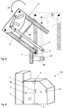
- FIG. 1 shows a schematic view of an embodiment of a side panel with a door 2 and FIG. 2 shows a schematic representation of a section at the point AA after the FIG. 1 when the door is closed 2.
- the door 2 consists of a first wing 3 and a second wing 4.
- the first wing 3 of the door 2 via first hinges 5 on the machine frame 1 is rotatably mounted.
- two first hinges 5 arranged in a vertical axis are shown.
- the second wing 4 is held by second hinges 6 on the first wing 3.
- the hinges 6 have two axes of rotation.
- the first wing 3 and the second wing 4 are connected to each other via a carrier 10, wherein the two wings 3 and 4 are respectively rotatably supported in the carrier 10 via the support pins 14.
- the carrier 10 is connected via a further carrier pin 14 rotatably connected to a linkage 7.
- the other end of the linkage 7 is fixed in a pivot point 9 in a mounting 18 on the machine frame 1.
- two curved slots 15 are provided in the carrier 10. These serve a rocker arm 8 as guides.
- the rocker arm 8 is provided at its two ends with crank rocker pin 13, which engage in the two slots 15. In this case, the one crank rocker pin 13 with the second wing 4 and the other rocker pin 13 are rotatably connected to the linkage 7.
- FIG. 3 shows a schematic representation of a portion of the section at the point AA after FIG. 1 when the door 2 is half open 2.
- a rotational movement 11 about the carrier pin 14 via which the first wing 3 is connected to the carrier 10 also takes place. This is effected by the fact that the linkage 7 is connected via the attachment 18 with the machine frame 1 and thus a fixed distance between the pivot point on the machine frame and the carrier pin 14 with which the linkage 7 is connected to the carrier 10.
- the rotational movement 11 of the first wing 3 leads via the linkage 7 and the connection via the carrier pin 14 with the carrier 10 to the fact that the rocker arm 8 in the slot 15 via the crank rocker pin 13 changes its position.
- the change in position of the rocker arm 8 in the slots 15 causes by the connection via the crank rocker pin 13 with the second wing 4, a rotational movement 12 of the second wing about the carrier pin 14 with which the second wing 4 is connected to the carrier 10.
- the rotational movements 11 of the first wing 3 and the rotational movement 12 of the second wing 4 are directed opposite. A continuation of these movements leads to a position of the two wings 3 and 4 as in FIG. 4 shown.
- FIG. 4 shows a schematic representation of the section at the point AA after the FIG. 1 with the door open 2.
- the first wing 4 is compared to the first hinges 5 relative to the machine frame 1 FIG. 2 rotated by 90 degrees, which has a rotational movement 11 to the carrier pin 14 also by 90 degrees result.
- the rocker arm 8 has reached its end position by the leadership of the crank rocker pin 13 in the slots 15 in the carrier 10.
- the first wing 3 is thereby arranged parallel to the second wing 4.
- FIG. 5 shows a schematic representation of the section at the point AA after the FIG. 1 with the door open and pivoted 2.
- the two wings 3 and 4 are arranged parallel to each other and are held together by a magnet 16.
- the linkage 7 is provided in the attachment 18 on the machine frame 1 with a releasable lock 17. After releasing the lock 17, the linkage 7 is no longer connected to the machine frame 1 and the two wings 3 and 4 can be pivoted about the first hinges 5 together with a rotational movement 19. This ensures that the entire door can be pivoted away from the work area.
- FIG. 6 shows a schematic view of a card 20 with a side panel.
- the side panel is provided with a door with two wings 3 and 4.
- the door has two door handles 21, which are arranged on the second wing 4 in the embodiment shown.
- the second wing 4 is pivoted about the second hinges 6 and about the carrier 10 (not shown).
- the rocker arm 8 and the linkage 7 By coupling with the first wing 3 via the rocker arm 8 and the linkage 7 is simultaneously a pivoting of the first wing 3 to the first hinges fifth
Landscapes
- Engineering & Computer Science (AREA)
- Textile Engineering (AREA)
- General Engineering & Computer Science (AREA)
- Preliminary Treatment Of Fibers (AREA)
- Mechanical Engineering (AREA)
- Civil Engineering (AREA)
- Structural Engineering (AREA)
- Casings For Electric Apparatus (AREA)
Applications Claiming Priority (1)
| Application Number | Priority Date | Filing Date | Title |
|---|---|---|---|
| CH01044/17A CH714076A1 (de) | 2017-08-22 | 2017-08-22 | Maschinenverkleidung. |
Publications (1)
| Publication Number | Publication Date |
|---|---|
| EP3447174A1 true EP3447174A1 (fr) | 2019-02-27 |
Family
ID=63014343
Family Applications (1)
| Application Number | Title | Priority Date | Filing Date |
|---|---|---|---|
| EP18184604.9A Withdrawn EP3447174A1 (fr) | 2017-08-22 | 2018-07-20 | Revêtement de la machine |
Country Status (3)
| Country | Link |
|---|---|
| EP (1) | EP3447174A1 (fr) |
| CN (1) | CN109423711A (fr) |
| CH (1) | CH714076A1 (fr) |
Cited By (3)
| Publication number | Priority date | Publication date | Assignee | Title |
|---|---|---|---|---|
| CN112359444A (zh) * | 2020-10-29 | 2021-02-12 | 四川力王无纺制品科技有限公司 | 一种无纺布生产装置 |
| CN114737263A (zh) * | 2022-03-21 | 2022-07-12 | 广东百如森羽绒制品有限公司 | 一种自动化羽绒蓬松除铁一体设备 |
| DE102021204139A1 (de) | 2021-04-26 | 2022-10-27 | James Hardie Europe Gmbh | Rohrmanschette, Brandschutzmanschette mit derartiger Rohrmanschette, Deckendurchführung, Decke mit derartiger Deckendurchführung und Verfahren zur Montage einer Deckendurchführung |
Citations (6)
| Publication number | Priority date | Publication date | Assignee | Title |
|---|---|---|---|---|
| US3017926A (en) * | 1959-05-05 | 1962-01-23 | Robert L Dickerson | Bi-fold door assembly |
| JPS5112723U (fr) * | 1974-07-05 | 1976-01-30 | ||
| DE29505908U1 (de) * | 1995-04-06 | 1995-06-14 | Christmann & Pfeifer GmbH & Co KG, 35236 Breidenbach | Schrank |
| DE10242929A1 (de) * | 2002-09-16 | 2004-03-18 | Trützschler GmbH & Co KG | Vorrichtung an einer Spinnereivorbereitungsmaschine, insbesondere Karde, mit einer Maschinenverkleidung |
| CN201835030U (zh) * | 2010-10-11 | 2011-05-18 | 青岛天一集团红旗纺织机械有限公司 | 粗纱机折叠式锭翼防护罩 |
| EP2551387A1 (fr) * | 2011-07-28 | 2013-01-30 | Marzoli S.P.A. | Ensemble d'essieu |
Family Cites Families (4)
| Publication number | Priority date | Publication date | Assignee | Title |
|---|---|---|---|---|
| DD99398A1 (fr) * | 1972-02-01 | 1973-08-13 | ||
| EP0195101B1 (fr) * | 1985-03-20 | 1989-05-24 | Carl Sigerist AG | Porte repliable avec panneau élastique |
| CN2592661Y (zh) * | 2002-11-23 | 2003-12-17 | 江苏省金坛市纺织机械总厂 | 梳棉机前门启闭装置 |
| DE20311189U1 (de) * | 2003-07-21 | 2003-09-25 | Arturo Salice S.P.A., Novedrate, Como | Hebevorrichtung für eine zweiflüglige Faltklappe oder -tür |
-
2017
- 2017-08-22 CH CH01044/17A patent/CH714076A1/de not_active Application Discontinuation
-
2018
- 2018-07-20 EP EP18184604.9A patent/EP3447174A1/fr not_active Withdrawn
- 2018-08-22 CN CN201810960086.0A patent/CN109423711A/zh active Pending
Patent Citations (6)
| Publication number | Priority date | Publication date | Assignee | Title |
|---|---|---|---|---|
| US3017926A (en) * | 1959-05-05 | 1962-01-23 | Robert L Dickerson | Bi-fold door assembly |
| JPS5112723U (fr) * | 1974-07-05 | 1976-01-30 | ||
| DE29505908U1 (de) * | 1995-04-06 | 1995-06-14 | Christmann & Pfeifer GmbH & Co KG, 35236 Breidenbach | Schrank |
| DE10242929A1 (de) * | 2002-09-16 | 2004-03-18 | Trützschler GmbH & Co KG | Vorrichtung an einer Spinnereivorbereitungsmaschine, insbesondere Karde, mit einer Maschinenverkleidung |
| CN201835030U (zh) * | 2010-10-11 | 2011-05-18 | 青岛天一集团红旗纺织机械有限公司 | 粗纱机折叠式锭翼防护罩 |
| EP2551387A1 (fr) * | 2011-07-28 | 2013-01-30 | Marzoli S.P.A. | Ensemble d'essieu |
Cited By (4)
| Publication number | Priority date | Publication date | Assignee | Title |
|---|---|---|---|---|
| CN112359444A (zh) * | 2020-10-29 | 2021-02-12 | 四川力王无纺制品科技有限公司 | 一种无纺布生产装置 |
| DE102021204139A1 (de) | 2021-04-26 | 2022-10-27 | James Hardie Europe Gmbh | Rohrmanschette, Brandschutzmanschette mit derartiger Rohrmanschette, Deckendurchführung, Decke mit derartiger Deckendurchführung und Verfahren zur Montage einer Deckendurchführung |
| CN114737263A (zh) * | 2022-03-21 | 2022-07-12 | 广东百如森羽绒制品有限公司 | 一种自动化羽绒蓬松除铁一体设备 |
| CN114737263B (zh) * | 2022-03-21 | 2023-05-09 | 广东百如森羽绒制品有限公司 | 一种自动化羽绒蓬松除铁一体设备 |
Also Published As
| Publication number | Publication date |
|---|---|
| CH714076A1 (de) | 2019-02-28 |
| CN109423711A (zh) | 2019-03-05 |
Similar Documents
| Publication | Publication Date | Title |
|---|---|---|
| EP0654573B1 (fr) | Boíte, notamment boíte à bagages pour le toit d'un véhicule | |
| DE102012111397B4 (de) | Motorhaubenverriegelungsvorrichtung mit Zwei-Stufen-Führung für ein Fahrzeug | |
| EP3088646B1 (fr) | Dispositif de guidage pour une porte coulissante | |
| EP2147178B1 (fr) | Agencement de charnière | |
| EP3904625A1 (fr) | Rail de guidage d'un chariot d'une porte de meuble | |
| EP3299550A1 (fr) | Ouverture de porte électrique pour porte battante pourvue d'un verrou magnétique | |
| CH714076A1 (de) | Maschinenverkleidung. | |
| EP2194181B1 (fr) | Appareil d'entretien du linge doté d'un élément de préhension pivotant verticalement | |
| EP3441549B1 (fr) | Verrouillage de porte | |
| EP0633974B1 (fr) | Charniere | |
| EP2689083B1 (fr) | Armoire, en particulier armoire pour bouteilles de gaz | |
| EP1103690B1 (fr) | Exutoire de désenfumage | |
| DE10127864C1 (de) | Schaltschrank für eine elektrische Schaltanlage mit einer Tür | |
| DE102006021636B3 (de) | Schließvorrichtung | |
| DE2924551A1 (de) | Tuerkonstruktion fuer fahrzeuge, bestehend aus einer ein- oder zweifluegeligen tuer | |
| EP1651831B1 (fr) | Ensemble constituant une partie d'un mecanisme de fermeture | |
| DE102013227005B4 (de) | Fahrzeugtüranordnung | |
| DE10122526B4 (de) | Karusselltür mit Nachtabschluss | |
| DE69117733T2 (de) | Vorrichtung zum Öffnen und Schliessen von mehreren Flügeln durch kombiniertes Schwenken und Schieben von denselben | |
| CH620494A5 (en) | Locking device | |
| EP3296492A1 (fr) | Systeme de guidage de porte coulissante et porte coulissante comprenant un systeme de guidage et vehicule en etant equipe | |
| DE2614753B2 (de) | Vorrichtung zum oeffnen und schliessen von tueren | |
| EP0705953B1 (fr) | Charnière | |
| AT395337B (de) | Verriegelungsvorrichtung | |
| DE10301046A1 (de) | Drehbeschlag für die verdeckte Anordnung an Türen oder Fenstern |
Legal Events
| Date | Code | Title | Description |
|---|---|---|---|
| PUAI | Public reference made under article 153(3) epc to a published international application that has entered the european phase |
Free format text: ORIGINAL CODE: 0009012 |
|
| AK | Designated contracting states |
Kind code of ref document: A1 Designated state(s): AL AT BE BG CH CY CZ DE DK EE ES FI FR GB GR HR HU IE IS IT LI LT LU LV MC MK MT NL NO PL PT RO RS SE SI SK SM TR |
|
| AX | Request for extension of the european patent |
Extension state: BA ME |
|
| STAA | Information on the status of an ep patent application or granted ep patent |
Free format text: STATUS: THE APPLICATION IS DEEMED TO BE WITHDRAWN |
|
| 18D | Application deemed to be withdrawn |
Effective date: 20190828 |