EP3447295A1 - Offener verdichter - Google Patents
Offener verdichter Download PDFInfo
- Publication number
- EP3447295A1 EP3447295A1 EP17848842.5A EP17848842A EP3447295A1 EP 3447295 A1 EP3447295 A1 EP 3447295A1 EP 17848842 A EP17848842 A EP 17848842A EP 3447295 A1 EP3447295 A1 EP 3447295A1
- Authority
- EP
- European Patent Office
- Prior art keywords
- open
- oil supply
- orbiting
- drive bearing
- drive shaft
- Prior art date
- Legal status (The legal status is an assumption and is not a legal conclusion. Google has not performed a legal analysis and makes no representation as to the accuracy of the status listed.)
- Withdrawn
Links
- 239000000314 lubricant Substances 0.000 claims description 78
- 230000002093 peripheral effect Effects 0.000 claims description 30
- 230000004308 accommodation Effects 0.000 abstract 2
- 239000003921 oil Substances 0.000 abstract 2
- 239000010687 lubricating oil Substances 0.000 abstract 1
- 230000006835 compression Effects 0.000 description 25
- 238000007906 compression Methods 0.000 description 25
- 239000003507 refrigerant Substances 0.000 description 21
- 239000012530 fluid Substances 0.000 description 7
- 230000001050 lubricating effect Effects 0.000 description 2
- 230000000149 penetrating effect Effects 0.000 description 2
- 230000000630 rising effect Effects 0.000 description 2
- 238000007599 discharging Methods 0.000 description 1
- 230000000694 effects Effects 0.000 description 1
- 239000007788 liquid Substances 0.000 description 1
- 239000002184 metal Substances 0.000 description 1
- 230000000452 restraining effect Effects 0.000 description 1
- 238000007789 sealing Methods 0.000 description 1
Images



Classifications
-
- F—MECHANICAL ENGINEERING; LIGHTING; HEATING; WEAPONS; BLASTING
- F04—POSITIVE - DISPLACEMENT MACHINES FOR LIQUIDS; PUMPS FOR LIQUIDS OR ELASTIC FLUIDS
- F04C—ROTARY-PISTON, OR OSCILLATING-PISTON, POSITIVE-DISPLACEMENT MACHINES FOR LIQUIDS; ROTARY-PISTON, OR OSCILLATING-PISTON, POSITIVE-DISPLACEMENT PUMPS
- F04C18/00—Rotary-piston pumps specially adapted for elastic fluids
- F04C18/02—Rotary-piston pumps specially adapted for elastic fluids of arcuate-engagement type, i.e. with circular translatory movement of co-operating members, each member having the same number of teeth or tooth-equivalents
- F04C18/0207—Rotary-piston pumps specially adapted for elastic fluids of arcuate-engagement type, i.e. with circular translatory movement of co-operating members, each member having the same number of teeth or tooth-equivalents both members having co-operating elements in spiral form
- F04C18/0215—Rotary-piston pumps specially adapted for elastic fluids of arcuate-engagement type, i.e. with circular translatory movement of co-operating members, each member having the same number of teeth or tooth-equivalents both members having co-operating elements in spiral form where only one member is moving
-
- F—MECHANICAL ENGINEERING; LIGHTING; HEATING; WEAPONS; BLASTING
- F04—POSITIVE - DISPLACEMENT MACHINES FOR LIQUIDS; PUMPS FOR LIQUIDS OR ELASTIC FLUIDS
- F04C—ROTARY-PISTON, OR OSCILLATING-PISTON, POSITIVE-DISPLACEMENT MACHINES FOR LIQUIDS; ROTARY-PISTON, OR OSCILLATING-PISTON, POSITIVE-DISPLACEMENT PUMPS
- F04C18/00—Rotary-piston pumps specially adapted for elastic fluids
- F04C18/02—Rotary-piston pumps specially adapted for elastic fluids of arcuate-engagement type, i.e. with circular translatory movement of co-operating members, each member having the same number of teeth or tooth-equivalents
- F04C18/0207—Rotary-piston pumps specially adapted for elastic fluids of arcuate-engagement type, i.e. with circular translatory movement of co-operating members, each member having the same number of teeth or tooth-equivalents both members having co-operating elements in spiral form
- F04C18/0246—Details concerning the involute wraps or their base, e.g. geometry
- F04C18/0253—Details concerning the base
-
- F—MECHANICAL ENGINEERING; LIGHTING; HEATING; WEAPONS; BLASTING
- F04—POSITIVE - DISPLACEMENT MACHINES FOR LIQUIDS; PUMPS FOR LIQUIDS OR ELASTIC FLUIDS
- F04C—ROTARY-PISTON, OR OSCILLATING-PISTON, POSITIVE-DISPLACEMENT MACHINES FOR LIQUIDS; ROTARY-PISTON, OR OSCILLATING-PISTON, POSITIVE-DISPLACEMENT PUMPS
- F04C29/00—Component parts, details or accessories of pumps or pumping installations, not provided for in groups F04C18/00 - F04C28/00
- F04C29/02—Lubrication; Lubricant separation
- F04C29/023—Lubricant distribution through a hollow driving shaft
Definitions
- the present invention relates to an open-type compressor.
- a metal housing internally has a crankshaft rotationally driven by an electric motor or an engine, an eccentric shaft disposed at a position offset from the crankshaft, an orbiting scroll rotatably supported by the eccentric shaft, and a fixed scroll facing the orbiting scroll (for example, refer to PTL 1).
- the orbiting scroll revolves around an axis of the crankshaft without any rotation, that is, the orbiting scroll performs orbiting movement. In this manner, a volume of a compression chamber formed between the fixed scroll and the orbiting scroll is changed so that a fluid introduced into the compression chamber is compressed.
- the eccentric shaft is pivotably disposed inside a bottomed cylindrical boss formed in an end plate of the orbiting scroll via a drive bearing.
- the drive bearing is lubricated by a mist-like lubricant fed into the housing from the outside of the housing together with the fluid serving as a compression target.
- the drive bearing is accommodated inside an orbiting end plate of the orbiting scroll. Therefore, in some cases, depending on an operation condition of the open-type compressor, it may be difficult to sufficiently supply the mist-like lubricant to the drive bearing. If the lubricant is insufficiently supplied, the drive bearing is poorly lubricated, thereby causing a possibility that the drive bearing may be abnormally worn due to a load generated when the fluid is compressed between the fixed scroll and the orbiting scroll.
- the present invention aims to provide an open-type compressor capable of stably supplying a lubricant to a drive bearing.
- an open-type compressor including a drive shaft to be rotationally driven around a central axis, a crank pin integrally formed in an end portion of the drive shaft, and being eccentric from the central axis in a direction orthogonal to the central axis, a drive bearing into which the crank pin is to be inserted, an orbiting scroll having an orbiting end plate having a drive bearing accommodating portion for accommodating the drive bearing, and an orbiting wrap extending from the orbiting end plate toward a side opposite to a side having the crank pin in an axial direction in which the central axis extends, and a housing accommodating the drive shaft, the crank pin, and the orbiting scroll, and having an oil introduction portion which introduces a lubricant to be supplied to the drive bearing from the outside.
- the orbiting end plate internally has an oil passage that allows a first opening which is open on an outer peripheral surface of the orbiting end plate and a second opening which is open inside the drive bearing accommodating portion to communicate with each other.
- a fluid is suctioned into a compression chamber while the orbiting end plate performs orbiting movement.
- Pressure of the first opening which is open on the outer peripheral surface of the orbiting end plate becomes lower than pressure in the second opening which is open inside the drive bearing accommodating portion. Therefore, the fluid starts to flow from the second opening toward the first opening inside the oil passage.
- the lubricant contained inside the drive bearing accommodating portion is suctioned from the second opening which is open inside the drive bearing accommodating portion.
- the lubricant smoothly flows in the vicinity of the drive bearing, thereby restraining the lubricant from being stagnant.
- the oil passage may extend in a radial direction inside the orbiting end plate.
- a flowing direction of the lubricant inside the oil passage can be coincident with a direction of a centrifugal force acting on the orbiting end plate. Therefore, the centrifugal force of the orbiting end plate can be efficiently utilized so as to allow the lubricant inside the oil passage to flow. As a result, the lubricant can more smoothly flow in the vicinity of the drive bearing.
- the first opening may be formed at a position different from a position of the oil introduction portion in a circumferential direction around the central axis.
- the first opening and the oil introduction portion are separated from each other. Therefore, a refrigerant flowing from the oil introduction portion is less likely to flow into the oil passage from the first opening. Accordingly, it is possible to prevent the lubricant from being reduced in the vicinity of the drive bearing since the lubricant for lubricating the drive bearing is flushed with the refrigerant reversely flowing inside the oil passage.
- the oil passage may be disposed in the orbiting end plate while avoiding a stepped portion formed on a surface on a side having the orbiting wrap.
- the stepped portion of the orbiting end plate on which stress is concentrated and the oil passage are formed at the same position. Accordingly, it is possible to prevent the orbiting end plate from being partially thinned. Therefore, it is possible to restrain strength from being weakened in the vicinity of the stepped portion of the orbiting end plate on which the stress is concentrated.
- the drive shaft internally may have an oil supply passage having a first oil supply opening which is open while facing a space into which the lubricant is introduced inside the housing, and a second oil supply opening which is open while facing a space having the drive bearing.
- the lubricant can be supplied to the drive bearing accommodating portion through the oil supply passage from the space in which the lubricant is introduced into the housing. In this manner, a new lubricant can be stably supplied to the drive bearing.
- the second oil supply opening may be formed at a position facing the drive bearing in the axial direction.
- the lubricant can be directly supplied to the drive bearing through the oil supply passage.
- the oil supply passage may extend in the axial direction at a position offset to a side opposite to the crank pin across the central axis.
- a space for forming the oil supply passage is likely to be secured at a position close to the drive bearing in the radial direction. Therefore, the oil supply passage can be formed at the position close to the drive bearing.
- the oil supply passage may be formed by allowing the drive shaft and a balance weight disposed in the drive shaft so as to negate an eccentric force generated by orbiting of the crank pin and the orbiting scroll to communicate with each other.
- the lubricant can be supplied to the drive bearing, even if the balance weight is provided.
- the second oil supply opening may be formed in a tip portion of the crank pin located inside the drive bearing.
- the lubricant can be directly supplied to the drive bearing through the oil supply passage.
- an open-type compressor including a drive shaft to be rotationally driven around a central axis, a crank pin integrally formed in an end portion of the drive shaft, and eccentric from the central axis in a direction orthogonal to the central axis, a drive bearing into which the crank pin is to be inserted, an orbiting scroll having an orbiting end plate having a drive bearing accommodating portion for accommodating the drive bearing, and an orbiting wrap extending from the orbiting end plate toward a side opposite to a side having the crank pin in an axial direction in which the central axis extends, and a housing accommodating the drive shaft, the crank pin, and the orbiting scroll, and having an oil introduction portion which introduces a lubricant to be supplied to the drive bearing from the outside.
- the drive shaft internally has an oil supply passage having a first oil supply opening which is open while facing a space into which the lubricant is introduced inside the housing, and a second oil supply opening which is open while facing a space having the
- the lubricant can be stably supplied to the drive bearing.
- Fig. 1 is a sectional view illustrating a configuration of an open-type scroll compressor according to a first embodiment.
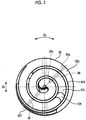
- Fig. 2 is a view when an orbiting scroll of the open-type scroll compressor is viewed in an axial direction.
- Fig. 3 is an enlarged sectional view illustrating a partial configuration of the open-type scroll compressor.
- an open-type scroll compressor (open-type compressor) 1A includes a housing 2, a front housing 3, a drive shaft 5, a scroll compression mechanism 6, a main bearing 7, and a sub-bearing 8.
- the housing 2 accommodates the drive shaft 5, a crank pin 51 (to be described later), the scroll compression mechanism 6 including an orbiting scroll 62 (to be described later), the main bearing 7, and the sub-bearing 8.
- the housing 2 extends in an axial direction Da along a central axis X.
- the housing 2 has a bottomed cylindrical shape in which one end portion 2a is open and the other end portion 2b is closed.
- a suction opening (oil introduction portion) 21 and a discharge port 22 are formed on an outer peripheral surface of the housing 2.
- the suction opening 21 (oil introduction portion) introduces a refrigerant (refrigerant gas) and a mist-like lubricant which are fluids into the housing 2 from the outside.
- the discharge port 22 discharges the refrigerant compressed by the scroll compression mechanism 6 outward of the housing 2.
- axial direction Da A direction in which the central axis X extends
- Dr A radial direction based on the central axis X
- Dc a direction around the drive shaft centered on the central axis X
- the front housing 3 is attached to the housing 2 so as to close an opening on one end portion 2a side of the housing 2.
- the front housing 3 is fixed to the housing 2, thereby internally forming a space hermetically sealed with the housing 2.
- the scroll compression mechanism 6 and the drive shaft 5 are accommodated inside this hermetically sealed space.
- the front housing 3 has a bearing holding portion 31 in a portion to be inserted into the housing 2.
- the bearing holding portion 31 extends in a cylindrical shape toward the other end portion 2b of the housing 2.
- the bearing holding portion 31 has a first oil supply passage 81 penetrating through the bearing holding portion 31.
- the first oil supply passage 81 communicates with an inner space S3 inside the bearing holding portion 31 between the main bearing 7 and the sub-bearing 8.
- the front housing 3 has a second oil supply passage 82 which allows an inner space S3 and an outer peripheral side of the sub-bearing 8 inside a through-hole 32 to communicate with each other.
- a central portion of the front housing 3 has the through-hole 32 penetrating in the axial direction Da.
- the drive shaft 5 is rotationally driven around the central axis X.
- the drive shaft 5 extends in the axial direction Da.
- the drive shaft 5 is rotatably supported by the front housing 3 via the main bearing 7 and the sub-bearing 8.
- One end portion 5a which is one side of the drive shaft 5 in the axial direction Da protrudes outward from the front housing 3 in a state where the drive shaft 5 is inserted into the through-hole 32.
- a lip seal 9 is disposed to maintain sealing performance between the drive shaft 5 and the through-hole 32.
- the drive shaft 5 has a disk-shaped disk portion 5d in an end portion on the other side (on the other end portion 2b side of the housing 2) in the axial direction Da.
- the crank pin 51 On the other side in the axial direction Da of the disk portion 5d of the drive shaft 5, the crank pin 51 is disposed at a position eccentric as much as a predetermined dimension in the radial direction Dr which is a direction orthogonal to the central axis X of the drive shaft 5.
- the crank pin 51 protrudes from an end portion of the disk portion 5d of the drive shaft 5 toward the other end portion 2b of the housing 2. Therefore, the crank pin 51 is formed integrally with an end portion on the other side of the drive shaft 5 in the axial direction Da. If the drive shaft 5 is rotated around the central axis X, the crank pin 51 orbits along a circular orbit whose radius is set to a dimension in which the crank pin 51 is eccentric with respect to the central axis X in the radial direction Dr.
- the main bearing 7 is fixed to the inside of the bearing holding portion 31 of the front housing 3.
- the disk portion 5d is fitted into the main bearing 7 so as to be rotatably supported.
- the sub-bearing 8 is located on the front housing 3 side with respect to the main bearing 7.
- the sub-bearing 8 is disposed inside the through-hole 32 of the front housing 3.
- the drive shaft 5 is rotatably supported via the sub-bearing 8 in an intermediate portion in the axial direction Da between one end portion 5a and the disk portion 5d.
- a pulley 11 is rotatably disposed in the front housing 3 via the bearing 10.
- a belt for transmitting a driving force from a driving source such as a motor and an engine is wound around the pulley 11.
- the pulley 11 and one end portion 5a of the drive shaft 5 are connected to each other via an electromagnetic clutch 12.
- the drive shaft 5 is rotated around the central axis X if external power for driving the pulley 11 is transmitted to the drive shaft 5 via the electromagnetic clutch 12.
- the scroll compression mechanism 6 is connected to the drive shaft 5.
- the scroll compression mechanism 6 includes a fixed scroll 61 and an orbiting scroll 62.
- the fixed scroll 61 integrally has a disk-shaped fixed end plate 61a and a spirally wounded fixed wrap 61b rising to the front housing 3 side (one side in the axial direction Da) with respect to the fixed end plate 61a.
- the fixed end plate 61a is fixed to the other end portion 2b of the housing 2 via a bolt 63.
- a central portion of the fixed end plate 61a has a discharge port 64 for discharging the refrigerant compressed by the scroll compression mechanism 6.
- the fixed wrap 61b is formed so that a height in the axial direction Da is gradually lowered from an outer peripheral side toward an inner peripheral side.
- a groove bottom surface 61c which is a surface on a side having the fixed wrap 61b gradually is formed so that the height is gradually raised from the outer peripheral side to the inner peripheral side on a side where the fixed wrap 61b rises.
- An O-ring 69 is disposed on the other side in the axial direction Da of the outer peripheral surface of the fixed end plate 61a. The O-ring 69 is in close contact with the inner peripheral surface of the housing 2.
- a space between the inner peripheral surface of the housing 2 and the outer peripheral side of the fixed end plate 61a is divided into a discharge chamber S2 on the other side in the axial direction Da with respect to the O-ring 69 and a suction chamber S1 on one side in the axial direction Da in which the front housing 3 is located with respect to the O-ring 69.
- the suction chamber S1 communicates with the suction opening 21 formed in the housing 2.
- a low pressure refrigerant circulating in a refrigerating cycle is suctioned through the suction opening 21, and the refrigerant is suctioned into the compression chamber 65 via the suction chamber S1.
- the orbiting scroll 62 integrally has a disk-shaped orbiting end plate 62a and a spirally wound orbiting wrap 62b rising to the fixed scroll 61 side (the other side in the axial direction Da) with respect to the orbiting end plate 62a.
- the orbiting wrap 62 b extends toward a side in the axial direction Da which is opposite to a side where the crank pin 51 is located with respect to the orbiting end plate 62a.
- the orbiting wrap 62b is formed so that the height in the axial direction Da is gradually lowered from the outer peripheral side toward the inner peripheral side.
- a groove bottom surface 62c which is a surface on a side having the orbiting wrap 62b is formed so that the height is gradually raised from the outer peripheral side toward the inner peripheral side on the side where the orbiting wrap 62b rises. Therefore, the groove bottom surface 62c has a stepped portion 62t in which a length of the orbiting end plate 62a in the axial direction Da varies.
- a drive bearing accommodating portion 66 for accommodating the drive bearing 67 is formed on a surface opposite to the groove bottom surface 62c of the orbiting end plate 62a in the axial direction Da.
- the drive bearing accommodating portion 66 has a cylindrical shape protruding to one side in the axial direction Da.
- the crank pin 51 is inserted into the drive bearing 67 via a drive bush 68. That is, the drive bearing 67 is disposed in a cylindrical shape so as to cover the crank pin 51 from the outside in the radial direction Dr.
- the drive bearing 67 accommodates the drive bush 68 fixed to the outer peripheral surface of the crank pin 51 in a pivotable state. In this manner, since the drive shaft 5 is rotated around the central axis X, the orbiting scroll 62 is driven so as to freely and smoothly revolve and orbit around the fixed scroll 61 together with the crank pin 51 which orbits along the circular orbit.
- the orbiting end plate 62a internally has an oil passage 86 extending outward in the radial direction Dr from the central portion of the orbiting end plate 62a in the radial direction Dr.
- two oil passages 86 according to the present embodiment are formed at positions different as much as 180° from each other in the circumferential direction Dc so as to interpose the central axis X therebetween with respect to the orbiting end plate 62a.
- the oil passage 86 is not limited to an example in which two are formed with respect to the orbiting end plate 62a.
- only one oil passage 86 may be formed with respect to the orbiting end plate 62a, or three or more oil passages 86 may be formed.
- each of the oil passages 86 allows a first opening 86a which is open on an outer peripheral surface 62f of the orbiting end plate 62a and a second opening 86b which is open inside the drive bearing accommodating portion 66 to communicate with each other.
- the oil passage 86 linearly extends to the outer peripheral surface 62f inside the orbiting end plate 62a in the radial direction Dr.
- the second opening 86b is formed on a surface facing one side of the drive bearing accommodating portion 66 in the axial direction Da so as to face the drive bearing 67.
- the second opening 86b is formed so as to project inward in the radial direction Dr from the inner peripheral surface to which the drive bearing 67 of the drive bearing accommodating portion 66 is attached. Therefore, the second opening 86b is formed inside the drive bearing accommodating portion 66 so as to be visible when the drive bearing accommodating portion 66 is viewed from one side in the axial direction Da.
- an opening area of the second opening 86b has an opening area having a size equal to or larger than 1/2 of a flow path cross section parallel to the axial direction Da of the oil passage 86.
- this oil passage 86 is formed at a position avoiding the stepped portion 62t of the groove bottom surface 62c in the orbiting end plate 62a. That is, the oil passage 86 is formed so as to be located at the position different from the position of the stepped portion 62t of the groove bottom surface 62c in the circumferential direction Dc.
- a main balance weight 71 and a sub-balance weight 72 which negate an eccentric force generated by orbiting of the crank pin 51 and the orbiting scroll 62 are disposed in the drive shaft 5.
- the main balance weight 71 is disposed between the drive shaft 5 and the orbiting scroll 62 in order to eliminate imbalance caused by the orbiting scroll 62 which orbits eccentrically with respect to the central axis X.
- the main balance weight 71 is located so as to be adjacent to the other side in the axial direction Da with respect to the disk portion 5d.
- the sub-balance weight 72 is disposed between the disk portion 5d of the drive shaft 5 and the sub-bearing 8 in order to eliminate the imbalance caused by the orbiting scroll 62 which orbits eccentrically with respect to the central axis X.
- the sub-balance weight 72 is located so as to be adjacent to one side in the axial direction Da with respect to the disk portion 5d.
- the fixed wrap 61b of the fixed scroll 61 and the orbiting wrap 62b of the orbiting scroll 62 are disposed so as to mesh with each other.
- a pair of compression chambers 65 is symmetrically formed with respect to a scroll center between the fixed scroll 61 and the orbiting scroll 62.
- the compression chambers 65 are partitioned by the fixed end plate 61a and the fixed wrap 61b, and the orbiting end plate 62a and the orbiting wrap 62b so as to be continuous in a spirally wound shape.
- the scroll compression mechanism 6 has a configuration capable of so-called three-dimensionally compressing the refrigerant.
- This scroll compression mechanism 6 is driven by the drive shaft 5, and the refrigerant flowing into the housing 2 from the suction opening 21 formed in the housing 2 is suctioned into the compression chamber 65 from the outer peripheral side.
- the refrigerant suctioned into the compression chamber 65 is compressed by moving the compression chamber 65 from an outer peripheral position to a center position while the volume of the compression chamber 65 is gradually reduced.
- the compressed refrigerant is supplied from the discharge port 64 formed in the fixed end plate 61a of the fixed scroll 61 to the discharge chamber S2 formed in a gap between the fixed end plate 61a of the fixed scroll 61 and the other end portion 2b of the housing 2. Thereafter, the refrigerant is discharged from the discharge port 22 to the refrigerating cycle side outside the housing 2.
- a mist-like lubricant together with the fluid is introduced into the housing 2 from the suction opening 21.
- a portion of the mist-like lubricant introduced into the housing 2 from the suction opening 21 is introduced into the inner space S3 of the bearing holding portion 31 through the first oil supply passage 81.
- the lubricant is supplied to the main bearing 7 by the portion of the lubricant introduced into the inner space S3.
- the portion of the mist-like lubricant introduced into the inner space S3 is supplied into the through-hole 32 through the second oil supply passage 82. In this manner, the lubricant is supplied to the sub-bearing 8.
- the scroll compression mechanism 6 suctions the refrigerant into the compression chamber 65 from the suction chamber S1 disposed on the outer peripheral side.
- the pressure of the first opening 86a which is open on the outer peripheral surface 62f of the orbiting end plate 62a becomes lower than the pressure of the second opening 86b which is open inside the drive bearing accommodating portion 66.
- the refrigerant or the lubricant starts to flow by being suctioned from the second opening 86b disposed on the drive bearing accommodating portion 66 side toward the first opening 86a disposed on the outer peripheral side communicating with the suction chamber S1.
- the lubricant contained inside the drive bearing accommodating portion 66 is suctioned from the second opening 86b which is open inside the drive bearing accommodating portion 66.
- the portion of the mist-like lubricant introduced into the housing 2 from the suction opening 21 is suctioned into the drive bearing accommodating portion 66 which accommodates the drive bearing 67. Therefore, the lubricant can smoothly flow in the vicinity of the drive bearing 67, and the lubricant is restrained from being stagnant. In this manner, the lubricant can be stably supplied to the drive bearing 67.
- the oil passage 86 is formed so as to linearly extend to the outer peripheral surface 62f in the radial direction Dr inside the orbiting end plate 62a. Therefore, if a hole extending from the outer peripheral surface 62f in the radial direction Dr is formed in the orbiting end plate 62a, the oil passage 86 can be formed, and the oil passage 86 can be easily processed.
- the oil passage 86 extends in the radial direction Dr. Accordingly, a flowing direction of the lubricant inside the oil passage 86 can be coincident with a direction of a centrifugal force acting on the orbiting end plate 62a. Therefore, the centrifugal force of the orbiting end plate 62a can be efficiently utilized so as to allow the lubricant inside the oil passage 86 to flow toward the first opening 86a from the second opening 86b. As a result, the lubricant can more smoothly flow in the vicinity of the drive bearing 67.
- the oil passage 86 is disposed while avoiding the stepped portion 62t of the orbiting end plate 62a. Therefore, the stepped portion 62t of the orbiting end plate 62a whose thickness varies and the oil passage 86 are formed at the same position. Accordingly, it is possible to prevent the orbiting end plate 62a from being partially thinned. Therefore, it is possible to restrain strength from being weakened in the vicinity of the stepped portion 62t of the orbiting end plate 62a on which stress is concentrated.
- the opening area of the second opening 86b which is open inside the drive bearing accommodating portion 66 in the oil passage 86 is set to a size equal to or larger than 1/2 of a cross section of a portion 86c extending in radial direction Dr of the orbiting end plate 62a. Accordingly, it is possible to restrain clogging when the lubricant flows to the second opening 86b. Therefore, the lubricant contained inside the drive bearing accommodating portion 66 can be efficiently suctioned from the second opening 86b, thereby enabling the lubricant to reliably flow in the vicinity of the drive bearing 67.
- the open-type compressor illustrated in the second embodiment has a different oil passage. Therefore, in the description of the second embodiment, the same reference numerals will be given to elements which are the same as those according to the first embodiment, and repeated description will be omitted. That is, configurations of the open-type compressor which are common to the configurations described in the first embodiment will be omitted in the description.
- an oil passage 86A according to the second embodiment is disposed so as to avoid not only the stepped portion 62t but also a position which overlaps the suction opening 21 in the circumferential direction Dc around the central axis X. Therefore, a first opening 860a according to the second embodiment is formed at a position of the circumferential direction Dc is formed at a position different from the position of the suction opening 21 in the circumferential direction Dc.
- the refrigerant may reversely flow (liquid backflow) in some cases.
- the respective positions of the first opening 860a and the suction opening 21 are separated from each other in the circumferential direction Dc. Therefore, even if the refrigerant reversely flows, the refrigerant flowing from the suction opening 21 is less likely to flow into the oil passage 86A from the first opening 860a. Therefore, it is possible to prevent the lubricant from being reduced in the vicinity of the drive bearing 67 since the lubricant for lubricating the drive bearing 67 is flushed with the refrigerant reversely flowing inside the oil passage 86A.
- a configuration of a third embodiment described below is different from that of the first embodiment and the second embodiment in that the drive shaft has an oil supply passage. Therefore, the same reference numerals will be given to elements which are the same as those according to the first embodiment and the second embodiment, and repeated description will be omitted.
- Fig. 5 is a sectional view illustrating a configuration of the open-type scroll compressor according to this embodiment.
- a drive shaft oil supply passage (oil supply passage) 83 for supplying the lubricant to the drive bearing 67 is formed inside the drive shaft 5.
- the drive shaft oil supply passage 83 supplies the lubricant from the inner space S3 serving as a space into which the lubricant is introduced, to the drive bearing accommodating portion 66 serving as a space where the drive bearing 67 is located.
- the drive shaft oil supply passage 83 according to the third embodiment linearly extends in the axial direction Da.
- the drive shaft oil supply passage 83 is formed at a position offset to a side opposite to the crank pin 51 across the central axis X in the circumferential direction Dc.
- the drive shaft oil supply passage 83 is formed at a position whose phase is different as much as 180° from that of the crank pin 51 in the circumferential direction Dc around the central axis X.
- the drive shaft oil supply passage 83 has a first oil supply opening 83a which is open to face the inner space S3 inside the housing 2 and a second oil supply opening 83b which is open to face the drive bearing accommodating portion 66.
- the drive shaft oil supply passage 83 is configured to include a third oil supply passage 831 formed in the disk portion 5d, a fourth oil supply passage 832 formed in the main balance weight 71, and a fifth oil supply passage 833 formed in the sub-balance weight 72.
- the first oil supply opening 83a and the second oil supply opening 83b according to the third embodiment are formed at positions offset to a side opposite to the crank pin 51 across the central axis X.
- the first oil supply opening 83a is formed at the position which is the same as the position of the second oil supply opening 83b in the circumferential direction Dc and the radial direction Dr.
- the second oil supply opening 83b is formed so as to face a surface facing one side of the drive bearing 67 in the axial direction Da.
- the third oil supply passage 831 penetrates the disk portion 5d in the axial direction Da.
- the third oil supply passage 831 linearly extends parallel to the central axis X.
- the fourth oil supply passage 832 penetrates the main balance weight 71 in the axial direction Da.
- the fourth oil supply passage 832 linearly extends parallel to the central axis X.
- the fourth oil supply passage 832 is formed at a position communicating with the third oil supply passage 831.
- An opening on the other side of the fourth oil supply passage 832 in the axial direction Da is the second oil supply opening 83b.
- the fifth oil supply passage 833 penetrates the sub-balance weight 72 in the axial direction Da.
- the fifth oil supply passage 833 linearly extends parallel to the central axis X.
- the fifth oil supply passage 833 is formed at a position communicating with the third oil supply passage 831.
- An opening on one side of the fifth oil supply passage 833 in the axial direction Da is the first oil supply opening 83a.
- the inner diameter of the fourth oil supply passage 832 of the main balance weight 71 and the fifth oil supply passage 833 of the sub-balance weight 72 is larger than the inner diameter of the third oil supply passage 831 formed in the disk portion 5d.
- the lubricant can be supplied to the drive bearing 67 inside the drive bearing accommodating portion 66 from the inner space S3 into which the lubricant is introduced, through the third oil supply passage 831, the fourth oil supply passage 832, and the fifth oil supply passage 833. In this manner, the new lubricant can be stably supplied to the drive bearing 67.
- the third oil supply passage 831, the fourth oil supply passage 832, and the fifth oil supply passage 833 are offset to the side opposite to the crank pin 51. Therefore, each space for forming the third oil supply passage 831, the fourth oil supply passage 832, and the fifth oil supply passage 833 with respect to the disk portion 5d, the main balance weight 71, and the sub-balance weight 72 is likely to be secured at the position close to the drive bearing 67 in the radial direction Dr. Therefore, the third oil supply passage 831, the fourth oil supply passage 832, and the fifth oil supply passage 833 can be formed at the position close to the drive bearing 67.
- the second oil supply opening 83b is open so as to face the drive bearing 67 in the axial direction Da. Therefore, the lubricant can be directly supplied to the drive bearing 67 through the drive shaft oil supply passage 83. In this manner, the lubricant can be more reliably supplied to the drive bearing 67.
- a portion of the drive shaft oil supply passage 83 is formed in the main balance weight 71 and the sub-balance weight 72. Therefore, even in a case where the main balance weight 71 and the sub-balance weight 72 are provided, the lubricant can be supplied to the drive bearing 67 by forming the fourth oil supply passage 832 and the fifth oil supply passage 833.
- a configuration of a fourth embodiment described below is different from that of the third embodiment in that the fourth embodiment employs a different configuration of the oil supply passage. Therefore, the same reference numerals will be given to elements which are the same as those according to the first to third embodiments, and repeated description will be omitted.
- Fig. 6 is a sectional view illustrating a configuration of the open-type scroll compressor according to the fourth embodiment.
- a drive shaft oil supply passage (oil supply passage) 88 for supplying the lubricant to the drive bearing 67 is formed in the drive shaft 5 and the crank pin 51.
- the drive shaft oil supply passage 88 penetrates the disk portion 5d and the crank pin 51 in a direction including the axial direction Da.
- the drive shaft oil supply passage 88 according to the present embodiment linearly extends in a direction inclined with respect to the axial direction Da.
- the drive shaft oil supply passage 88 has a first oil supply opening 88a which is open in the disk portion 5d while facing the inner space S3, and a second oil supply opening 88b which is open inside the drive bearing accommodating portion 66.
- the drive shaft oil supply passage 88 according to the fourth embodiment is not formed in the main balance weight 71 or the sub-balance weight 72.
- the first oil supply opening 88a is formed on a surface 5g of the disk portion 5d on the front housing 3 side.
- the second oil supply opening 88b is formed in a tip portion of the crank pin 51 located inside the drive bearing 67.
- the second oil supply opening 88b according to the present embodiment is formed in a tip surface 51g which is an end surface facing the other side of the tip portion in the axial direction Da.
- the lubricant can be supplied to the tip surface 51g located in the rear inside the drive bearing 67 through the drive shaft oil supply passage 88 from the inner space S3 in which the lubricant is introduced into the housing 2. Accordingly, the lubricant can be directly supplied to the drive bearing 67. In this manner, a new lubricant can be stably supplied to the drive bearing 67.
- the drive shaft oil supply passage 88 is formed to be inclined with respect to the central axis X.
- the drive shaft oil supply passage 88 may be formed to be inclined so as to be separated outward in the radial direction Dr from the central axis X.
- the mist-like lubricant flowing into the drive shaft oil supply passage 88 is likely to be discharged toward the drive bearing 67 from the second oil supply opening 88b by the centrifugal force.
- the fifth embodiment described below includes the oil passage and the oil supply passage which are described in the first embodiment, the third embodiment, and the fourth embodiment.
- Fig. 7 is a sectional view illustrating a configuration of the open-type scroll compressor according to the fifth embodiment.
- an open-type scroll compressor 1D has the oil passage 86, the drive shaft oil supply passage 83, and the drive shaft oil supply passage 88.
- the lubricant can be supplied to the drive bearing 67 from the inner space S3 by the drive shaft oil supply passage 83 and the drive shaft oil supply passage 88 which are different from those according to the above-described embodiments. Therefore, the lubricant can be directly supplied to the drive bearing 67. In this manner, a new lubricant can be stably supplied to the drive bearing 67. Furthermore, since the oil passage 86 is formed, the lubricant contained in the drive bearing accommodating portion 66 is suctioned from the second opening 86b. As a result, the lubricant more smoothly flows in the vicinity of the drive bearing 67. Therefore, while the new lubricant is supplied to the drive bearing 67, the lubricant can be restrained from being stagnant in the vicinity of the drive bearing 67.
- the new lubricant can be more stably supplied to the drive bearing 67.
- the fourth embodiment described above includes all of the oil passage 86 described in the first embodiment, the drive shaft oil supply passage 88 described in the third embodiment, and the drive shaft oil supply passage 88 described in the fourth embodiment. However, a configuration may be adopted which includes at least two of these.
- the lubricant can be stably supplied to the drive bearing.
Landscapes
- Engineering & Computer Science (AREA)
- Mechanical Engineering (AREA)
- General Engineering & Computer Science (AREA)
- Rotary Pumps (AREA)
- Applications Or Details Of Rotary Compressors (AREA)
Applications Claiming Priority (2)
| Application Number | Priority Date | Filing Date | Title |
|---|---|---|---|
| JP2016174902A JP6756551B2 (ja) | 2016-09-07 | 2016-09-07 | 開放型圧縮機 |
| PCT/JP2017/032261 WO2018047904A1 (ja) | 2016-09-07 | 2017-09-07 | 開放型圧縮機 |
Publications (2)
| Publication Number | Publication Date |
|---|---|
| EP3447295A1 true EP3447295A1 (de) | 2019-02-27 |
| EP3447295A4 EP3447295A4 (de) | 2019-07-03 |
Family
ID=61561623
Family Applications (1)
| Application Number | Title | Priority Date | Filing Date |
|---|---|---|---|
| EP17848842.5A Withdrawn EP3447295A4 (de) | 2016-09-07 | 2017-09-07 | Offener verdichter |
Country Status (3)
| Country | Link |
|---|---|
| EP (1) | EP3447295A4 (de) |
| JP (1) | JP6756551B2 (de) |
| WO (1) | WO2018047904A1 (de) |
Family Cites Families (13)
| Publication number | Priority date | Publication date | Assignee | Title |
|---|---|---|---|---|
| JPS5849715B2 (ja) * | 1978-10-30 | 1983-11-05 | サンデン株式会社 | 容積式流体圧縮装置 |
| JPS5535154A (en) * | 1978-09-04 | 1980-03-12 | Sanden Corp | Volume type fluid compressor |
| JPS56143386A (en) * | 1980-04-09 | 1981-11-09 | Hitachi Ltd | Enclosed scroll compressor |
| JPS57105582A (en) * | 1980-12-24 | 1982-07-01 | Hitachi Ltd | Scroll fluid machinery |
| JPS58130096U (ja) * | 1982-12-27 | 1983-09-02 | サンデン株式会社 | 容積式流体圧縮装置 |
| US5308231A (en) * | 1993-05-10 | 1994-05-03 | General Motors Corporation | Scroll compressor lubrication |
| JPH084667A (ja) * | 1994-06-15 | 1996-01-09 | Toyota Autom Loom Works Ltd | スクロール型圧縮機 |
| US5888057A (en) * | 1996-06-28 | 1999-03-30 | Sanden Corporation | Scroll-type refrigerant fluid compressor having a lubrication path through the orbiting scroll |
| JPH1130188A (ja) * | 1997-07-10 | 1999-02-02 | Mitsubishi Heavy Ind Ltd | スクロール型圧縮機 |
| JP2000352377A (ja) | 1999-06-08 | 2000-12-19 | Mitsubishi Heavy Ind Ltd | 開放型圧縮機 |
| JP2012062854A (ja) * | 2010-09-17 | 2012-03-29 | Keihin Corp | スクロール型圧縮機 |
| JP5561302B2 (ja) * | 2012-03-29 | 2014-07-30 | 株式会社豊田自動織機 | スクロール圧縮機 |
| CN105604936B (zh) * | 2016-03-04 | 2017-10-24 | 广东正力精密机械有限公司 | 一种无油涡旋空气压缩机 |
-
2016
- 2016-09-07 JP JP2016174902A patent/JP6756551B2/ja active Active
-
2017
- 2017-09-07 WO PCT/JP2017/032261 patent/WO2018047904A1/ja not_active Ceased
- 2017-09-07 EP EP17848842.5A patent/EP3447295A4/de not_active Withdrawn
Also Published As
| Publication number | Publication date |
|---|---|
| JP2018040293A (ja) | 2018-03-15 |
| EP3447295A4 (de) | 2019-07-03 |
| JP6756551B2 (ja) | 2020-09-16 |
| WO2018047904A1 (ja) | 2018-03-15 |
Similar Documents
| Publication | Publication Date | Title |
|---|---|---|
| US10415567B2 (en) | Scroll compressor with axial flux motor | |
| EP2416015B1 (de) | Spiralverdichter | |
| CN104903583B (zh) | 涡旋式压缩机 | |
| KR101099923B1 (ko) | 스크롤형 압축기 | |
| JPWO2013171957A1 (ja) | 電動圧縮機 | |
| EP3073117B1 (de) | Spiralverdichter | |
| US10539139B2 (en) | Compressor | |
| WO2017163814A1 (ja) | スクロール型圧縮機 | |
| JP2014132158A (ja) | スクロール型圧縮機 | |
| US10533554B2 (en) | Cylinder-rotation compressor with improved vane and suction passage locations | |
| WO2018145091A1 (en) | Scroll compressor with axial flux motor | |
| US20180187679A1 (en) | Scroll compressor | |
| US20200217315A1 (en) | Scroll compressor | |
| EP3447295A1 (de) | Offener verdichter | |
| EP3315781B1 (de) | Offener verdichter | |
| EP3409948B1 (de) | Hermetischer zweistufiger verdichter | |
| KR101897776B1 (ko) | 압축기 | |
| JP4681322B2 (ja) | スクロール圧縮機 | |
| JP2018159285A (ja) | スクロール型圧縮機 | |
| EP4600495A1 (de) | Spiralverdichter | |
| WO2024122093A1 (ja) | 両回転式スクロール型圧縮機 | |
| JP2006183461A (ja) | 流体機械 | |
| EP3150855B1 (de) | Offener verdichter | |
| EP3461992A1 (de) | Offener verdichter | |
| JP2006070711A (ja) | スクロール圧縮機 |
Legal Events
| Date | Code | Title | Description |
|---|---|---|---|
| STAA | Information on the status of an ep patent application or granted ep patent |
Free format text: STATUS: THE INTERNATIONAL PUBLICATION HAS BEEN MADE |
|
| PUAI | Public reference made under article 153(3) epc to a published international application that has entered the european phase |
Free format text: ORIGINAL CODE: 0009012 |
|
| STAA | Information on the status of an ep patent application or granted ep patent |
Free format text: STATUS: REQUEST FOR EXAMINATION WAS MADE |
|
| 17P | Request for examination filed |
Effective date: 20181121 |
|
| AK | Designated contracting states |
Kind code of ref document: A1 Designated state(s): AL AT BE BG CH CY CZ DE DK EE ES FI FR GB GR HR HU IE IS IT LI LT LU LV MC MK MT NL NO PL PT RO RS SE SI SK SM TR |
|
| AX | Request for extension of the european patent |
Extension state: BA ME |
|
| A4 | Supplementary search report drawn up and despatched |
Effective date: 20190531 |
|
| RIC1 | Information provided on ipc code assigned before grant |
Ipc: F04C 29/02 20060101ALI20190524BHEP Ipc: F04C 18/02 20060101AFI20190524BHEP |
|
| DAV | Request for validation of the european patent (deleted) | ||
| DAX | Request for extension of the european patent (deleted) | ||
| GRAP | Despatch of communication of intention to grant a patent |
Free format text: ORIGINAL CODE: EPIDOSNIGR1 |
|
| STAA | Information on the status of an ep patent application or granted ep patent |
Free format text: STATUS: GRANT OF PATENT IS INTENDED |
|
| INTG | Intention to grant announced |
Effective date: 20200408 |
|
| STAA | Information on the status of an ep patent application or granted ep patent |
Free format text: STATUS: THE APPLICATION IS DEEMED TO BE WITHDRAWN |
|
| 18D | Application deemed to be withdrawn |
Effective date: 20200819 |