EP3447352A1 - Ensemble de soupape pour une turbomachine - Google Patents
Ensemble de soupape pour une turbomachine Download PDFInfo
- Publication number
- EP3447352A1 EP3447352A1 EP17187065.2A EP17187065A EP3447352A1 EP 3447352 A1 EP3447352 A1 EP 3447352A1 EP 17187065 A EP17187065 A EP 17187065A EP 3447352 A1 EP3447352 A1 EP 3447352A1
- Authority
- EP
- European Patent Office
- Prior art keywords
- valve
- valve seat
- cone
- steam
- arrangement
- Prior art date
- Legal status (The legal status is an assumption and is not a legal conclusion. Google has not performed a legal analysis and makes no representation as to the accuracy of the status listed.)
- Withdrawn
Links
Images


Classifications
-
- F—MECHANICAL ENGINEERING; LIGHTING; HEATING; WEAPONS; BLASTING
- F16—ENGINEERING ELEMENTS AND UNITS; GENERAL MEASURES FOR PRODUCING AND MAINTAINING EFFECTIVE FUNCTIONING OF MACHINES OR INSTALLATIONS; THERMAL INSULATION IN GENERAL
- F16K—VALVES; TAPS; COCKS; ACTUATING-FLOATS; DEVICES FOR VENTING OR AERATING
- F16K47/00—Means in valves for absorbing fluid energy
- F16K47/04—Means in valves for absorbing fluid energy for decreasing pressure or noise level, the throttle being incorporated in the closure member
-
- B—PERFORMING OPERATIONS; TRANSPORTING
- B22—CASTING; POWDER METALLURGY
- B22F—WORKING METALLIC POWDER; MANUFACTURE OF ARTICLES FROM METALLIC POWDER; MAKING METALLIC POWDER; APPARATUS OR DEVICES SPECIALLY ADAPTED FOR METALLIC POWDER
- B22F10/00—Additive manufacturing of workpieces or articles from metallic powder
- B22F10/20—Direct sintering or melting
- B22F10/28—Powder bed fusion, e.g. selective laser melting [SLM] or electron beam melting [EBM]
-
- F—MECHANICAL ENGINEERING; LIGHTING; HEATING; WEAPONS; BLASTING
- F16—ENGINEERING ELEMENTS AND UNITS; GENERAL MEASURES FOR PRODUCING AND MAINTAINING EFFECTIVE FUNCTIONING OF MACHINES OR INSTALLATIONS; THERMAL INSULATION IN GENERAL
- F16K—VALVES; TAPS; COCKS; ACTUATING-FLOATS; DEVICES FOR VENTING OR AERATING
- F16K1/00—Lift valves or globe valves, i.e. cut-off apparatus with closure members having at least a component of their opening and closing motion perpendicular to the closing faces
- F16K1/32—Details
- F16K1/34—Cutting-off parts, e.g. valve members, seats
- F16K1/36—Valve members
- F16K1/38—Valve members of conical shape
-
- F—MECHANICAL ENGINEERING; LIGHTING; HEATING; WEAPONS; BLASTING
- F16—ENGINEERING ELEMENTS AND UNITS; GENERAL MEASURES FOR PRODUCING AND MAINTAINING EFFECTIVE FUNCTIONING OF MACHINES OR INSTALLATIONS; THERMAL INSULATION IN GENERAL
- F16K—VALVES; TAPS; COCKS; ACTUATING-FLOATS; DEVICES FOR VENTING OR AERATING
- F16K1/00—Lift valves or globe valves, i.e. cut-off apparatus with closure members having at least a component of their opening and closing motion perpendicular to the closing faces
- F16K1/32—Details
- F16K1/34—Cutting-off parts, e.g. valve members, seats
- F16K1/42—Valve seats
-
- F—MECHANICAL ENGINEERING; LIGHTING; HEATING; WEAPONS; BLASTING
- F16—ENGINEERING ELEMENTS AND UNITS; GENERAL MEASURES FOR PRODUCING AND MAINTAINING EFFECTIVE FUNCTIONING OF MACHINES OR INSTALLATIONS; THERMAL INSULATION IN GENERAL
- F16K—VALVES; TAPS; COCKS; ACTUATING-FLOATS; DEVICES FOR VENTING OR AERATING
- F16K47/00—Means in valves for absorbing fluid energy
- F16K47/08—Means in valves for absorbing fluid energy for decreasing pressure or noise level and having a throttling member separate from the closure member, e.g. screens, slots, labyrinths
-
- B—PERFORMING OPERATIONS; TRANSPORTING
- B22—CASTING; POWDER METALLURGY
- B22F—WORKING METALLIC POWDER; MANUFACTURE OF ARTICLES FROM METALLIC POWDER; MAKING METALLIC POWDER; APPARATUS OR DEVICES SPECIALLY ADAPTED FOR METALLIC POWDER
- B22F2999/00—Aspects linked to processes or compositions used in powder metallurgy
-
- B—PERFORMING OPERATIONS; TRANSPORTING
- B22—CASTING; POWDER METALLURGY
- B22F—WORKING METALLIC POWDER; MANUFACTURE OF ARTICLES FROM METALLIC POWDER; MAKING METALLIC POWDER; APPARATUS OR DEVICES SPECIALLY ADAPTED FOR METALLIC POWDER
- B22F5/00—Manufacture of workpieces or articles from metallic powder characterised by the special shape of the product
- B22F5/06—Manufacture of workpieces or articles from metallic powder characterised by the special shape of the product of threaded articles, e.g. nuts
-
- B—PERFORMING OPERATIONS; TRANSPORTING
- B33—ADDITIVE MANUFACTURING TECHNOLOGY
- B33Y—ADDITIVE MANUFACTURING, i.e. MANUFACTURING OF THREE-DIMENSIONAL [3D] OBJECTS BY ADDITIVE DEPOSITION, ADDITIVE AGGLOMERATION OR ADDITIVE LAYERING, e.g. BY 3D PRINTING, STEREOLITHOGRAPHY OR SELECTIVE LASER SINTERING
- B33Y80/00—Products made by additive manufacturing
-
- Y—GENERAL TAGGING OF NEW TECHNOLOGICAL DEVELOPMENTS; GENERAL TAGGING OF CROSS-SECTIONAL TECHNOLOGIES SPANNING OVER SEVERAL SECTIONS OF THE IPC; TECHNICAL SUBJECTS COVERED BY FORMER USPC CROSS-REFERENCE ART COLLECTIONS [XRACs] AND DIGESTS
- Y02—TECHNOLOGIES OR APPLICATIONS FOR MITIGATION OR ADAPTATION AGAINST CLIMATE CHANGE
- Y02P—CLIMATE CHANGE MITIGATION TECHNOLOGIES IN THE PRODUCTION OR PROCESSING OF GOODS
- Y02P10/00—Technologies related to metal processing
- Y02P10/25—Process efficiency
Definitions
- the invention relates to a valve arrangement for flowing through a flow medium, comprising a valve cone and a valve housing with a valve seat, wherein the valve arrangement is formed with a valve inlet and a valve outlet, wherein the valve cone is formed movable against the valve seat and a fluidic connection between the valve inlet and the Valve outlet establishes when the valve plug is spaced from the valve seat and the fluidic connection is closed when the valve plug is in contact with the valve seat.
- the invention relates to a method for producing a valve arrangement.
- Valves are used, for example, in steam power plants in which a high temperature steam at high pressure is passed through steam lines.
- the steam is generated in steam generators and first led via the steam lines to a high-pressure turbine section and then to a reheater in the steam generator.
- the steam is brought to a higher temperature and then fed to a medium-pressure turbine section.
- the steam flows into a low-pressure turbine section and from there into a condenser.
- the vapor condenses on cooled condenser tubes. The resulting condensate is recycled via pumps to preheaters or to the steam generator.
- the object of the invention is therefore to change the valve so that the noise emission is reduced.
- a valve arrangement for flowing through a flow medium comprising a valve cone and a valve housing with a valve seat, wherein the valve arrangement is formed with a valve inlet and a valve outlet, wherein the valve cone is designed to be movable against the valve seat and a fluidic connection between the valve inlet and the valve outlet when the poppet is spaced from the valve seat and the fluidic connection is closed when the poppet is in contact with the valve seat, the poppet or valve seat or poppet and valve seat being formed with a flow surface substantially parallel to the valve seat deviates circular shape.
- the flow medium flowing through the valve assembly flows along the flow surface.
- Current valves are designed with smooth flow surfaces.
- the valve cone or the valve seat or the valve cone and the valve seat are circular.
- the invention now goes the way that the flow surface does not have a circular shape. Rather, the invention goes assume that the flow surface has a changed structure distributed along the circumference.
- the altered structure is characterized by having regular mountains and valleys in the circumferential direction. As a result, the shape of the flow surface is chevron-shaped.
- the flow surface may also have a serrated configuration. This means that the poppet affects the flow through its jagged formation.
- valve cone or the valve seat is formed with the flow surface according to the invention.
- the deviation from a circular shape relates to a flow surface which is located after the passage of the gap between the valve cone and the valve seat.
- the inventive design of the flow surface leads to a turbulence of the flow of the flow medium.
- the flow medium is a vapor.
- the region of the valve arrangement is thus manufactured downstream of the valve seat in such a way that it has the shape of a chevron nozzle or star-shaped or jagged nozzle in order to influence the jet disintegration and thereby the acoustic emission.
- the contour deviating from the circular shape can be introduced either in the valve cone, in the valve seat or in the valve cone and in the valve seat.
- the deviating from the circular shape geometry provides a targeted vortex formation, which increases the beam breakage and certain Schallmoden be dammed targeted.
- the advantage of the invention is that the noise emission is reduced by a faster jet breakup. Likewise, it is possible to selectively attenuate sound modes, which leads to a reduction of valve vibrations.
- the geometry of the invention must be located downstream of the seat, so that the valve can still close pressure-tight.
- the Chevron Nozzles generate vortex structures that contribute to faster jet breakup.
- the FIG. 1 shows a valve assembly 1 according to the prior art.
- the valve arrangement comprises a valve cone 2.
- the valve cone 2 is fastened to a valve spindle 3.
- the valve spindle 3 can be moved in the direction of movement 4.
- the valve assembly 1 further comprises a valve housing 5.
- the valve housing 5 is formed around the valve cone 2.
- the passage 6 of the valve stem 3 through the valve housing 5 is sealed.
- Within the valve housing 5 there is a steam space 7.
- the valve arrangement 1 further comprises a steam inlet 8 and a steam outlet 9.
- a vapor (preferably from the steam generator) flows through the steam inlet 8.
- the steam flows out of the valve arrangement 1 to, for example, a steam turbine.
- valve assembly 1 The amount of steam flowing through the valve assembly 1 from the steam inlet 8 to the steam outlet 9 is regulated by the position of the valve cone 2 to a valve seat 10.
- valve assembly 1 In the FIG. 1 the valve assembly 1 is shown in an open state. This is illustrated by the spacing of the valve cone 2 to the valve seat 10. In a closed state of the valve arrangement 1, the valve cone 2 would be arranged such that it touches the valve seat 10 is applied so that no steam from the steam chamber 7 can flow into the steam outlet 9.
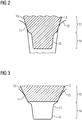
- the FIG. 2 shows an inventive arrangement of the valve cone 2.
- the FIG. 2 shows the arrangement of the valve plug 2 relative to the valve seat 10 in a closed state. This means that the valve cone 2 bears against the valve seat 10 at a contact line 11.
- the contact line 11 is circular in a cylindrical configuration of the valve cone 2. Other shapes of the valve cone 2, such as oval are also possible. Then, the contact line 11 would be an ellipse-like line as seen from above.
- the poppet 2 comprises a contact region 12.
- This contact region 12 of the poppet 2 has a substantially smooth flow surface 13.
- a steam flowing out of the steam inlet 8 thus flows on the smooth flow surface 13 in the direction of the steam outlet 9.
- the valve cone 2 comprises a downstream profile region 14. This profile region 14 is characterized in that it has a turbulence surface 15 which is opposite to the smooth surface Flow surface is not circular.
- the FIG. 2 shows a sectional view through the valve cone. 2
- FIG. 4 is a view from below of the poppet 2 to see.
- chevrons 17 are arranged, which have an influence on the steam flow.
- only one chevron is provided with the reference numeral 17.
- a serrated or star-shaped shape of the profile region 14 of the valve cone 2 may have.
- the number of spikes or chevrons can be adapted to the flow conditions.
- the FIG. 3 shows a way to arrange the profile area 14 in the region of the valve seat 10.
- the profile region 14 is executed in chevronförmiger, serrated or star-shaped design.
- the swirling surface 15 deviates substantially from the circular shape.
- the turbulence surface 15 leads to a turbulence of the flow.
- the swirling surface 15 is arranged after the passage of the vapor between the valve cone 2 and the valve seat 10. That is, the swirl surface 15 is located downstream to optimize swirling.
- the valve assembly 1 may be formed by an additive manufacturing process.
- the selective laser melting process offers.
Landscapes
- Engineering & Computer Science (AREA)
- General Engineering & Computer Science (AREA)
- Mechanical Engineering (AREA)
- Physics & Mathematics (AREA)
- Plasma & Fusion (AREA)
- Chemical & Material Sciences (AREA)
- Manufacturing & Machinery (AREA)
- Materials Engineering (AREA)
- Lift Valve (AREA)
- Details Of Valves (AREA)
Priority Applications (1)
| Application Number | Priority Date | Filing Date | Title |
|---|---|---|---|
| EP17187065.2A EP3447352A1 (fr) | 2017-08-21 | 2017-08-21 | Ensemble de soupape pour une turbomachine |
Applications Claiming Priority (1)
| Application Number | Priority Date | Filing Date | Title |
|---|---|---|---|
| EP17187065.2A EP3447352A1 (fr) | 2017-08-21 | 2017-08-21 | Ensemble de soupape pour une turbomachine |
Publications (1)
| Publication Number | Publication Date |
|---|---|
| EP3447352A1 true EP3447352A1 (fr) | 2019-02-27 |
Family
ID=59677133
Family Applications (1)
| Application Number | Title | Priority Date | Filing Date |
|---|---|---|---|
| EP17187065.2A Withdrawn EP3447352A1 (fr) | 2017-08-21 | 2017-08-21 | Ensemble de soupape pour une turbomachine |
Country Status (1)
| Country | Link |
|---|---|
| EP (1) | EP3447352A1 (fr) |
Citations (8)
| Publication number | Priority date | Publication date | Assignee | Title |
|---|---|---|---|---|
| US3187775A (en) * | 1961-08-21 | 1965-06-08 | Shaffer Tool Works | Flow bean |
| NL8602008A (nl) * | 1986-08-06 | 1988-03-01 | Grontmij N V | Klepsamenstel voor het begrenzen van de doorstroming door een vloeistofleiding. |
| US6082405A (en) * | 1996-07-09 | 2000-07-04 | Tac Ab | Valve cone, a valve and a valve manufacturing process |
| DE10146941A1 (de) * | 2001-09-24 | 2003-04-10 | Gen Motors Corp | Fluidventil |
| WO2009027810A2 (fr) * | 2007-08-31 | 2009-03-05 | Enologica Friulana S.A.S | Buse auto-nettoyante pour clarificateurs par flottation |
| US20150233493A1 (en) * | 2012-09-17 | 2015-08-20 | Paal Irgens HAGEVIK | Device to Reduce the Pressure of a Liquid Flow and a Regulating Valve |
| WO2016133497A1 (fr) * | 2015-02-17 | 2016-08-25 | Halliburton Energy Services, Inc. | Clapet à battant imprimé en 3d |
| US20160369905A1 (en) * | 2013-07-23 | 2016-12-22 | Kyb Corporation | Control valve |
-
2017
- 2017-08-21 EP EP17187065.2A patent/EP3447352A1/fr not_active Withdrawn
Patent Citations (8)
| Publication number | Priority date | Publication date | Assignee | Title |
|---|---|---|---|---|
| US3187775A (en) * | 1961-08-21 | 1965-06-08 | Shaffer Tool Works | Flow bean |
| NL8602008A (nl) * | 1986-08-06 | 1988-03-01 | Grontmij N V | Klepsamenstel voor het begrenzen van de doorstroming door een vloeistofleiding. |
| US6082405A (en) * | 1996-07-09 | 2000-07-04 | Tac Ab | Valve cone, a valve and a valve manufacturing process |
| DE10146941A1 (de) * | 2001-09-24 | 2003-04-10 | Gen Motors Corp | Fluidventil |
| WO2009027810A2 (fr) * | 2007-08-31 | 2009-03-05 | Enologica Friulana S.A.S | Buse auto-nettoyante pour clarificateurs par flottation |
| US20150233493A1 (en) * | 2012-09-17 | 2015-08-20 | Paal Irgens HAGEVIK | Device to Reduce the Pressure of a Liquid Flow and a Regulating Valve |
| US20160369905A1 (en) * | 2013-07-23 | 2016-12-22 | Kyb Corporation | Control valve |
| WO2016133497A1 (fr) * | 2015-02-17 | 2016-08-25 | Halliburton Energy Services, Inc. | Clapet à battant imprimé en 3d |
Similar Documents
| Publication | Publication Date | Title |
|---|---|---|
| DE69208222T2 (de) | Ventil mit einem geschlitzten Ventilsitz | |
| DE102004022063A1 (de) | Abgasdiffusor für eine Axialströmungsturbine | |
| EP2505808B1 (fr) | Dispositif de mélange de carburant et d'air dans un moteur à réaction | |
| DE10054244C2 (de) | Turbinenblattanordnung und Turbinenblatt für eine Axialturbine | |
| DE102009059318A1 (de) | Verfahren, Systeme und/oder Vorrichtungen im Zusammenhang mit Dampfturbinenauslassdiffusoren | |
| DE102020115426A1 (de) | Ventiltrimmvorrichtung zur Verwendung mit Ventilen | |
| EP2455665A2 (fr) | Chambre de combustion de turbine à gaz dotée d'un dispositif d'amenée d'air de refroidissement | |
| DE102010037844A1 (de) | Brennstoffdüsendichtungsabstandhalter und Verfahren zu seinem Einbau | |
| CH698570B1 (de) | Brennstoffdüse für eine Brennkammer. | |
| DE102018119730A1 (de) | Verbesserte Fluidleitungen | |
| DE102016213551A1 (de) | Düse für Wasser, insbesondere für einen Wasserwerfer | |
| EP3019793B1 (fr) | Insert de protection contre la chaleur pour conduite de carburant | |
| DE2447100C2 (de) | Brennkraftmaschine mit Aufladung nach dem Stoßverfahren | |
| EP3793807B1 (fr) | Joint pour étanchéifier un interstice entre deux conduits contenant des gaz d'échappement | |
| DE2545378A1 (de) | Gas-druckregelgeraet | |
| EP1153219B1 (fr) | Diffuseur sans pulsations de l'interface d'impact, et procede pour empecher les pulsations de l'interface d'impact de diffuseurs | |
| EP3447352A1 (fr) | Ensemble de soupape pour une turbomachine | |
| EP0035605A1 (fr) | Organe de fermeture pour milieux gazeux avec un dispositif pour amortir des vibrations acoustiques auto-amorçées dans des cavités | |
| EP2558781A1 (fr) | Générateur de turbulence pour un brûleur | |
| WO2000057030A1 (fr) | Aube de turbomachine | |
| DE112015004881B4 (de) | Hauptdampfventil und Dampfturbine | |
| DE112022002451T5 (de) | Dampfventil und energieerzeugungssystem | |
| DE10314941A1 (de) | Brennstoffinjektionseinrichtung für Gasturbinenbrenner | |
| DE102016003011B4 (de) | Durchflussmengenregler-Einheit sowie Verwendung einer solchen Durchflussmengenregler-Einheit | |
| EP3296523A1 (fr) | Dispositif de répartition d'un courant de masse dans deux courants massiques partiels |
Legal Events
| Date | Code | Title | Description |
|---|---|---|---|
| PUAI | Public reference made under article 153(3) epc to a published international application that has entered the european phase |
Free format text: ORIGINAL CODE: 0009012 |
|
| AK | Designated contracting states |
Kind code of ref document: A1 Designated state(s): AL AT BE BG CH CY CZ DE DK EE ES FI FR GB GR HR HU IE IS IT LI LT LU LV MC MK MT NL NO PL PT RO RS SE SI SK SM TR |
|
| AX | Request for extension of the european patent |
Extension state: BA ME |
|
| STAA | Information on the status of an ep patent application or granted ep patent |
Free format text: STATUS: THE APPLICATION IS DEEMED TO BE WITHDRAWN |
|
| 18D | Application deemed to be withdrawn |
Effective date: 20190828 |