EP3447412B1 - Appareil de réfrigération et/ou de congélation et procédé pour pour la fabrication du même - Google Patents
Appareil de réfrigération et/ou de congélation et procédé pour pour la fabrication du même Download PDFInfo
- Publication number
- EP3447412B1 EP3447412B1 EP18189939.4A EP18189939A EP3447412B1 EP 3447412 B1 EP3447412 B1 EP 3447412B1 EP 18189939 A EP18189939 A EP 18189939A EP 3447412 B1 EP3447412 B1 EP 3447412B1
- Authority
- EP
- European Patent Office
- Prior art keywords
- refrigerator
- evaporator
- freezer according
- accommodated
- assembly carrier
- Prior art date
- Legal status (The legal status is an assumption and is not a legal conclusion. Google has not performed a legal analysis and makes no representation as to the accuracy of the status listed.)
- Active
Links
Images

Classifications
-
- F—MECHANICAL ENGINEERING; LIGHTING; HEATING; WEAPONS; BLASTING
- F25—REFRIGERATION OR COOLING; COMBINED HEATING AND REFRIGERATION SYSTEMS; HEAT PUMP SYSTEMS; MANUFACTURE OR STORAGE OF ICE; LIQUEFACTION SOLIDIFICATION OF GASES
- F25D—REFRIGERATORS; COLD ROOMS; ICE-BOXES; COOLING OR FREEZING APPARATUS NOT OTHERWISE PROVIDED FOR
- F25D19/00—Arrangement or mounting of refrigeration units with respect to devices or objects to be refrigerated, e.g. infrared detectors
- F25D19/02—Arrangement or mounting of refrigeration units with respect to devices or objects to be refrigerated, e.g. infrared detectors plug-in type
-
- F—MECHANICAL ENGINEERING; LIGHTING; HEATING; WEAPONS; BLASTING
- F25—REFRIGERATION OR COOLING; COMBINED HEATING AND REFRIGERATION SYSTEMS; HEAT PUMP SYSTEMS; MANUFACTURE OR STORAGE OF ICE; LIQUEFACTION SOLIDIFICATION OF GASES
- F25D—REFRIGERATORS; COLD ROOMS; ICE-BOXES; COOLING OR FREEZING APPARATUS NOT OTHERWISE PROVIDED FOR
- F25D23/00—General constructional features
- F25D23/006—General constructional features for mounting refrigerating machinery components
-
- F—MECHANICAL ENGINEERING; LIGHTING; HEATING; WEAPONS; BLASTING
- F25—REFRIGERATION OR COOLING; COMBINED HEATING AND REFRIGERATION SYSTEMS; HEAT PUMP SYSTEMS; MANUFACTURE OR STORAGE OF ICE; LIQUEFACTION SOLIDIFICATION OF GASES
- F25D—REFRIGERATORS; COLD ROOMS; ICE-BOXES; COOLING OR FREEZING APPARATUS NOT OTHERWISE PROVIDED FOR
- F25D2201/00—Insulation
- F25D2201/10—Insulation with respect to heat
- F25D2201/14—Insulation with respect to heat using subatmospheric pressure
-
- F—MECHANICAL ENGINEERING; LIGHTING; HEATING; WEAPONS; BLASTING
- F25—REFRIGERATION OR COOLING; COMBINED HEATING AND REFRIGERATION SYSTEMS; HEAT PUMP SYSTEMS; MANUFACTURE OR STORAGE OF ICE; LIQUEFACTION SOLIDIFICATION OF GASES
- F25D—REFRIGERATORS; COLD ROOMS; ICE-BOXES; COOLING OR FREEZING APPARATUS NOT OTHERWISE PROVIDED FOR
- F25D23/00—General constructional features
- F25D23/06—Walls
- F25D23/061—Walls with conduit means
-
- F—MECHANICAL ENGINEERING; LIGHTING; HEATING; WEAPONS; BLASTING
- F25—REFRIGERATION OR COOLING; COMBINED HEATING AND REFRIGERATION SYSTEMS; HEAT PUMP SYSTEMS; MANUFACTURE OR STORAGE OF ICE; LIQUEFACTION SOLIDIFICATION OF GASES
- F25D—REFRIGERATORS; COLD ROOMS; ICE-BOXES; COOLING OR FREEZING APPARATUS NOT OTHERWISE PROVIDED FOR
- F25D2400/00—General features of, or devices for refrigerators, cold rooms, ice-boxes, or for cooling or freezing apparatus not covered by any other subclass
- F25D2400/40—Refrigerating devices characterised by electrical wiring
Definitions
- the invention relates to a refrigerator and / or freezer with a device body that has heat-insulating walls that enclose an interior space, as well as with a refrigerant circuit that includes a compressor, a condenser, a throttle and an evaporator as components.
- the invention also relates to a method for producing such a refrigerator and / or freezer.
- JPH09243234A, JP2007249537A and JPS4894247U disclose prior art refrigerators and / or freezers.
- vacuum-insulated cooling devices which are characterized by a particularly low heat loss, but which are complex to manufacture and in which the implementation of lines into the interior of the device is associated with great effort.
- the object of the invention is to provide a refrigerator and / or freezer which is simple and inexpensive to manufacture and maintain even in the case of vacuum insulation.
- the invention relates to a refrigerator and / or freezer with a device body that has heat-insulating walls that enclose an interior space, as well as with a refrigerant circuit that includes a compressor, a condenser, a throttle and an evaporator as components.
- the unit carrier comprises a machine section and an evaporator section connected to it, the compressor and the condenser in the machine section and the evaporator are accommodated in the evaporator section and that the unit carrier has a connection channel in which all cables and / or lines running between the machine section and the evaporator section are accommodated, a condensate line being accommodated in the connection channel.
- an assembly carrier with all components of the refrigerant circuit can be separated from the device body as a whole.
- This also includes the pipes and any other components of the refrigerant circuit such as dryers or collectors.
- both components of the warm side of the refrigerant circuit, i.e. the compressor and condenser, and components of the cold side of the refrigerant circuit, i.e. the evaporator, are installed together on a unit carrier that is separated from the unit body and removed from the cooling unit can be.
- these components can also be installed in a single work step by inserting the assembly carrier in the device.
- the unit carrier which is detachably connected to the device body, can be fastened, for example, by means of screw connections.
- the unit carrier can be detached from the device body without tools and, for example, is only connected to it by means of latching connections.
- the connecting channel can be completely enclosed by sections of the unit carrier or can be exposed at least on one side and / or at least in sections.
- connection channel is thermally insulated at least in sections.
- the connecting duct is preferably thermally insulated over its entire length.
- heat insulation material can be provided in the unit carrier and preferably in the evaporator section of the unit carrier, which is arranged along the connecting channel.
- the connecting channel can run at least in sections in an area of the unit carrier which borders on a heat-insulating wall of the device body.
- the connection channel can run along the underside of the evaporator section, whereby its outside at or near the heat insulating Floor of the interior runs. Thermal insulation of the connecting channel can therefore also be achieved, at least in part, by the insulating properties of the heat-insulating floor of the interior.
- a suction pipe and / or a capillary of the refrigerant circuit are received in the connecting channel.
- a condensate line is received in the connecting channel.
- the throttle of the refrigerant circuit can be a capillary that is passed through the connecting channel.
- the capillary can also be wound around the suction tube at least in sections within the connecting channel.
- a strong heat exchange between capillary and suction tube can take place within the preferably thermally insulated connection channel, which has a favorable effect on the energy efficiency of the device.
- the condensate line can be a hose feed-through.
- the device body has full vacuum insulation, the interior space being surrounded by a one-piece, box-shaped vacuum insulation body.
- the heat-insulating walls of the device body are sections of the vacuum insulation body in this embodiment.
- the vacuum insulation body comprises a barrier film and a support material arranged in the core enclosed by the barrier film.
- the device body can have a frame substructure which extends over the entire height of the device and surrounds the area of the interior space as well as forming a base area.
- the box-shaped vacuum insulation body can be used in this frame construction.
- the frame substructure can also serve to accommodate the assembly carrier. You can also form the bottom of the device body. It gives the device body stability.
- the vacuum insulation body In order to protect the vacuum insulation body, it can be provided that it is completely concealed. On the one hand, it can be provided that a plastic inner container is inserted into the box-shaped vacuum insulation body. Furthermore, it can be provided that the outside of the frame substructure is clad with wall panels and preferably wall sheets. The connection between the wall panels, the inner container, the vacuum insulation body and the frame substructure can be made by gluing, screwing, locking and preferably a combination thereof.
- the unit carrier is installed in the lower area of the device body.
- the installation of the heavy components of the refrigerant circuit in the lower (base) area of the device results in a high level of stability. Furthermore, a deep installation results in better ergonomics for the customer, since the compartments higher up are more accessible and the less accessible area in the base area of the device is taken up by the unit carrier. Ultimately, any condensation can simply flow downwards.
- components selected from the group of a machine room fan, a cold room fan, a control unit, a condensate tray and a power supply unit with cabling are installed on the unit carrier. This leads to a further simplification in the assembly of the device and to a simplification in the implementation of any repair work.
- components on the warm side of the refrigerant circuit such as a machine room fan, a control unit, a condensate tray or a power supply unit with cabling are to be arranged in the machine section and components on the cold side of the refrigerant circuit such as a cold room fan in the evaporator section.
- the connecting duct can also accommodate all cables and / or lines which, due to these additional components installed on the unit carrier, must also run between the machine section and the evaporator section.
- a supply line of a cooling chamber fan can run in the connecting channel.
- a heat insulation layer belonging to the device body is arranged in a free space lying next to the connection between the machine section and the evaporator section.
- the thermal insulation layer can be a section of the full vacuum insulation.
- the connection can be formed, for example, by a web running in the front area of the device, which belongs to the machine section or the evaporator section or is formed by a separate intermediate piece. In this case, the bottom of the cooled interior or the section of the vacuum insulation body and the inner container forming the interior bottom can be set back somewhat with respect to the opening plane of the interior.
- the thermal insulation layer is part of the body of the device and fills an area in the subframe between the machine section and the evaporator section and next to the connecting element.
- the connection itself can also comprise insulating material in order to avoid the formation of a thermal bridge in this area as well.
- the machine section is accommodated in a base space of the device body and the evaporator section is accommodated in the lowermost area of the interior.
- the machine section is below the evaporator section.
- the machine section is preferably dimensioned so that it completely fills the base space of the device body and the evaporator section is dimensioned such that it completely occupies the lowest area of the heat-insulated interior in such a way that the bottom and the lowermost sections of the rear wall and possibly also the side walls of the interior completely be covered by the evaporator section.
- the base space as well as the interior are preferably open towards the front so that the unit carrier can be pulled forwards out of the device body in the event of dismantling and, conversely, can be pushed into the device body from the front during assembly.
- the invention also relates to a method for producing a refrigerator and / or freezer according to the invention, the assembly carrier being inserted as a whole into the device body.
- the unit carrier is preferably pushed into the device body from the front.
- the unit carrier is preferably used in a lower area of the device body.
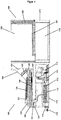
- the right figure of the Figure 1 shows an assembly carrier of a refrigerator and / or freezer according to the invention, which is generally identified by the reference symbol 100.
- the left figure of the Figure 1 shows a device body of a refrigerator and / or freezer according to the invention, which is generally identified by the reference numeral 200.
- the Figure 2 shows a sectional view through the lower region of a refrigerator and / or freezer device according to the invention, in which the assembly carrier 100 is inserted into the device body 200.
- the device body 200 comprises a frame substructure which forms a base space 210 with the device base in the lowest region and in which a box-shaped vacuum insulation body is received in the region above, which defines an interior space 220.
- the vacuum insulation body serves as thermal insulation for the interior space 220 and comprises a barrier film and a support material arranged in the core enclosed by the barrier film. It is laminated all around to protect the barrier film.
- a plastic inner container is inserted into the interior opening of the vacuum insulation body.
- the frame substructure is covered with a ceiling panel, a rear panel and two side panels. The section of the vacuum insulation body and of the inner container forming the interior floor 221 are set back somewhat with respect to the opening plane of the interior.
- the unit carrier 100 comprises a machine section 110 and an evaporator section 120 connected to it.
- the machine section 110 forms the lower part of the unit carrier 100 and is dimensioned so that it can be pushed into the base space 210 of the device body 200 from the front and occupies it completely.
- the evaporator section 120 is placed on the machine section 110 and dimensioned so that it can be pushed into the lowermost area of the heat-insulated interior 220 of the device body 200 from the front and occupies this completely, so that the bottom 221 and the lowermost sections of the side walls and the rear wall 222 of the interior 220 are completely covered by the evaporator section 120.
- the machine section 110 and the evaporator section 120 are only connected by means of a connecting web 130, which is located in the front region of the unit carrier 100. Behind the connecting web 130, a recess 140 is provided in the unit carrier 100 between the machine section 110 and the evaporator section 120, in which the vacuum-insulated floor 221 of the device body 200 can find space when the unit carrier 100 is pushed into the device body 200 from the front in such a way that the machine section 110 can be pushed into the base space 210 and the evaporator section 120 into the interior 220 of the device body 200.
- a compressor 111 and a condenser 112 are arranged in the machine section 110, the compressor 111 being located in the rear area and the condenser 112 being located in the front area of the machine section 110. Furthermore, a condensate tray 113 is arranged in the front region of the machine section 110 in thermal contact with the condenser 112.
- the compressor 111 is installed with a sprung suspension 114 in the rear region of the machine section 110.
- the rear side 211 of the base space 210 is closed by the wall section 211.
- a cooling air fan and a control unit are also arranged in the machine section 110, but are not shown separately in the figure for reasons of clarity.
- Electrical cabling with a power supply unit, which is arranged in the machine section and which can be connected to a power supply due to the delimitation of the base space 210 of the device body 200, is also not shown in detail in the figure.
- a cold air duct 121 is formed in the evaporator section 120 and extends from a suction opening 122 to an outlet opening 123.
- the evaporator 128 is located inside the cold air duct.
- the suction opening 122 is located at the front end of the evaporator section 120.
- the outlet opening 123 is located at the rear end of the evaporator section 120 and, when the unit carrier 100 is installed, is adjacent to the rear wall 222 of the device body 200 the cold air duct 121 is widened near the outlet opening 123 and forms a fan chamber 124 in which an evaporator fan 125 is arranged.
- the rear end piece of the upper cover 126 of the fan chamber 124 points vertically upwards and does not extend all the way to the rear end of the evaporator section, so that in the installed state of the assembly support 100 between the rear end piece of the upper cover 126 of the fan chamber 124 and the rear wall 222 of the device body 200, a vertical channel section is formed which opens into a vertical air duct, not shown in detail, in the area of the rear wall of the 222 located further up.
- the unit carrier 100 also has a connecting duct 150 in which all cables and lines 151 running between the machine section 110 and the evaporator section 120 are received.
- the connecting channel 150 is completely enclosed by housing parts of the assembly carrier 110. It is essentially thermally insulated over its entire length. For this purpose, on the one hand, thermal insulation material is provided in the evaporator section 120 of the assembly carrier 110.
- the connection channel runs from the rear of the evaporator section 120 along the underside of the evaporator section 120 and thus borders on one side of the heat-insulating floor 221 of the interior 220 of the device body 200 of the interior 220 of the device body 200 is reached.
- the lines 151 running in the connecting channel 150 are only shown collectively in the figure and not shown individually. Below them, however, are the suction pipe and the capillary of the refrigerant circuit, the capillary being wound around the suction pipe within the thermally insulated connecting channel 150. Furthermore, a condensation water hose runs within the connecting channel 150 and leads from the evaporator 128 to the condensation water tray 113. Furthermore, a supply line, which connects the evaporator fan 125 to the control unit and power supply of the machine section 110, runs in the connecting duct 150.
Landscapes
- Engineering & Computer Science (AREA)
- Chemical & Material Sciences (AREA)
- Combustion & Propulsion (AREA)
- Physics & Mathematics (AREA)
- Mechanical Engineering (AREA)
- Thermal Sciences (AREA)
- General Engineering & Computer Science (AREA)
- Devices That Are Associated With Refrigeration Equipment (AREA)
Claims (10)
- Appareil de réfrigération et/ou de congélation avec un corps d'appareil (200), qui présente des parois thermo-isolantes, qui renferment un espace intérieur (220), ainsi qu'avec un circuit de réfrigérant, qui comprend en tant que composants un compresseur (111), un condenseur (112), un élément d'étranglement et un évaporateur (128), dans lequel tous les composants du circuit de réfrigérant sont montés conjointement sur un support de groupe (100), qui peut être séparé dans son ensemble du corps d'appareil (200) et peut être retiré de l'appareil, dans lequel le support de groupe (100) comprend une section de machine (110) et une section d'évaporateur (120) reliée à celle-ci, dans lequel le compresseur (11) ainsi que le condenseur (112) sont logés dans la section de machine et l'évaporateur (128) est logé dans la section d'évaporateur (120) et dans lequel le support de groupe (100) présente un canal de liaison (150), dans lequel sont logés tous les câbles et/ou conduits (151) s'étendant entre la section de machine et la section d'évaporateur, caractérisé en ce qu'un conduit d'eau de condensation est logé dans le canal de liaison.
- Appareil de réfrigération et/ou de congélation selon la revendication 1, caractérisé en ce que le canal de liaison (150) est thermo-isolé au moins par endroits.
- Appareil de réfrigération et/ou de congélation selon l'une quelconque des revendications précédentes, caractérisé en ce que le canal de liaison (150) s'étend au moins par endroits dans une zone du support de groupe, qui jouxte une paroi thermo-isolante du corps d'appareil.
- Appareil de réfrigération et/ou de congélation selon l'une quelconque des revendications précédentes, caractérisé en ce qu'un tube d'aspiration et/ou un capillaire du circuit de réfrigérant sont logés dans le canal de liaison (150).
- Appareil de réfrigération et/ou de congélation selon l'une quelconque des revendications précédentes, caractérisé en ce que le corps d'appareil présente une isolation sous vide total, dans lequel l'espace intérieur (220) est entouré par un corps isolant sous vide traversant en forme de caisse.
- Appareil de réfrigération et/ou de congélation selon l'une quelconque des revendications précédentes, caractérisé en ce que le support de groupe (100) est monté dans la zone inférieure du corps d'appareil.
- Appareil de réfrigération et/ou de congélation selon l'une quelconque des revendications précédentes, caractérisé en ce qu'en outre un ou plusieurs composants choisis parmi le groupe d'un ventilateur d'espace de machine, d'un ventilateur d'espace de refroidissement, d'une unité de commande, d'une coque d'eau de condensation (113) et d'une partie de réseau avec câblage sont montés sur le support de groupe.
- Appareil de réfrigération et/ou de congélation selon l'une quelconque des revendications précédentes, caractérisé en ce qu'une couche thermo-isolante appartenant au corps d'appareil est disposée dans un espace libre se trouvant à côté de la liaison entre la section de machine (110) et la section d'évaporateur (120).
- Appareil de réfrigération et/ou de congélation selon l'une quelconque des revendications précédentes, caractérisé en ce que la section de machine (110) est logée dans un espace de socle du corps d'appareil et la section d'évaporateur (120) est logée dans la zone la plus basse de l'espace intérieur.
- Procédé de fabrication d'un appareil de réfrigération et/ou de congélation selon l'une quelconque des revendications précédentes,
caractérisé en ce
que le support de groupe (100) est inséré comme un tout dans le corps d'appareil (200).
Applications Claiming Priority (1)
| Application Number | Priority Date | Filing Date | Title |
|---|---|---|---|
| DE102017119045.7A DE102017119045A1 (de) | 2017-08-21 | 2017-08-21 | Kühl- und/oder Gerfriergerät |
Publications (2)
| Publication Number | Publication Date |
|---|---|
| EP3447412A1 EP3447412A1 (fr) | 2019-02-27 |
| EP3447412B1 true EP3447412B1 (fr) | 2021-01-13 |
Family
ID=63350408
Family Applications (1)
| Application Number | Title | Priority Date | Filing Date |
|---|---|---|---|
| EP18189939.4A Active EP3447412B1 (fr) | 2017-08-21 | 2018-08-21 | Appareil de réfrigération et/ou de congélation et procédé pour pour la fabrication du même |
Country Status (3)
| Country | Link |
|---|---|
| EP (1) | EP3447412B1 (fr) |
| DE (1) | DE102017119045A1 (fr) |
| ES (1) | ES2863372T3 (fr) |
Cited By (1)
| Publication number | Priority date | Publication date | Assignee | Title |
|---|---|---|---|---|
| EP4345404A1 (fr) * | 2022-09-27 | 2024-04-03 | Liebherr-Hausgeräte Lienz GmbH | Appareil de refroidissement et/ou de congélation |
Families Citing this family (1)
| Publication number | Priority date | Publication date | Assignee | Title |
|---|---|---|---|---|
| DE102022106725A1 (de) | 2022-03-03 | 2023-09-07 | Liebherr-Hausgeräte Lienz Gmbh | Kühl- und/oder Gefriergerät |
Citations (1)
| Publication number | Priority date | Publication date | Assignee | Title |
|---|---|---|---|---|
| JPS4894247U (fr) * | 1972-02-12 | 1973-11-10 |
Family Cites Families (9)
| Publication number | Priority date | Publication date | Assignee | Title |
|---|---|---|---|---|
| DE955148C (de) * | 1953-08-18 | 1956-12-27 | F & R Fischer K G | Tragbarer, elektrischer Kuehlbehaelter |
| JPS5422273U (fr) * | 1977-07-18 | 1979-02-14 | ||
| JPH04129086U (ja) * | 1991-05-13 | 1992-11-25 | 日本建鐵株式会社 | 横形冷蔵庫 |
| JPH09243234A (ja) * | 1996-03-05 | 1997-09-19 | Hoshizaki Electric Co Ltd | 冷却貯蔵庫における除霜排水蒸発装置 |
| JP3137946B2 (ja) * | 1998-09-22 | 2001-02-26 | 明星工業株式会社 | 断熱パネル及びその製造方法 |
| US6550255B2 (en) * | 2001-03-21 | 2003-04-22 | The Coca-Cola Company | Stirling refrigeration system with a thermosiphon heat exchanger |
| JP2007249537A (ja) * | 2006-03-15 | 2007-09-27 | Sanden Corp | 自動販売機 |
| JP4895848B2 (ja) * | 2007-02-08 | 2012-03-14 | 三洋電機株式会社 | 冷却装置 |
| EP2778580B1 (fr) * | 2013-03-15 | 2019-06-26 | Whirlpool Corporation | Construction d'armoire tubulaire à structure isolée sous vide |
-
2017
- 2017-08-21 DE DE102017119045.7A patent/DE102017119045A1/de not_active Withdrawn
-
2018
- 2018-08-21 ES ES18189939T patent/ES2863372T3/es active Active
- 2018-08-21 EP EP18189939.4A patent/EP3447412B1/fr active Active
Patent Citations (1)
| Publication number | Priority date | Publication date | Assignee | Title |
|---|---|---|---|---|
| JPS4894247U (fr) * | 1972-02-12 | 1973-11-10 |
Cited By (1)
| Publication number | Priority date | Publication date | Assignee | Title |
|---|---|---|---|---|
| EP4345404A1 (fr) * | 2022-09-27 | 2024-04-03 | Liebherr-Hausgeräte Lienz GmbH | Appareil de refroidissement et/ou de congélation |
Also Published As
| Publication number | Publication date |
|---|---|
| ES2863372T3 (es) | 2021-10-11 |
| DE102017119045A1 (de) | 2019-02-21 |
| EP3447412A1 (fr) | 2019-02-27 |
Similar Documents
| Publication | Publication Date | Title |
|---|---|---|
| EP3447412B1 (fr) | Appareil de réfrigération et/ou de congélation et procédé pour pour la fabrication du même | |
| WO2007031470A2 (fr) | Appareil frigorifique sans givre | |
| DE102009001825A1 (de) | Haushaltskältegerät mit einem ersten Lüfter und mindestens einen weiteren Lüfter zur Förderung von Kühlraumluft entlang der Oberfläche eines Verdampfers und zugehöriges Verfahren | |
| EP2522937A2 (fr) | Dispositif de vaporisation pour un appareil frigorifique encastrable ainsi qu'appareil frigorifique encastrable et procédé d'encastrement d'un appareil frigorifique encastrable | |
| EP3447414B1 (fr) | Appareil de réfrigération et/ou de congélation | |
| DE102017002599A1 (de) | Kühl- und/oder Gefriergerät | |
| EP3447418B1 (fr) | Appareil de réfrigération et/ou de congélation | |
| WO2006058819A1 (fr) | Appareil frigorifique encastrable | |
| DE4420149A1 (de) | Kühlanlage mit Kühlraum, sowie Isolierpaneel mit integrierten Luftkühlerbauelementen für einen Kühlraum | |
| EP3447413B1 (fr) | Appareil de réfrigération et/ou de congélation | |
| DE102016224389A1 (de) | No-Frost-Haushaltskältegerät mit zur Rückwand dichtender Trennplatte | |
| DE102023212101B4 (de) | Kältegerät und Verfahren zum Montieren eines Kältegeräts | |
| EP1728035A1 (fr) | Appareil frigorifique integre avec unite de socle | |
| WO2009000737A2 (fr) | Appareil frigorifique | |
| EP2461125A2 (fr) | Appareil de réfrigération et/ou de congélation | |
| DE19907124A1 (de) | Kältegerät | |
| EP1110041B1 (fr) | Dispositif evaporateur | |
| WO2005017425A1 (fr) | Appareil refrigerant en deux parties | |
| DE102012014342A1 (de) | System von mehreren Kühl- und/oder Gefriergeräten | |
| EP4265985B1 (fr) | Appareil frigorifique ménager pourvu de deux évaporateurs | |
| DE102017124425A1 (de) | Kühl- und oder Gefriergerät | |
| DE102017127472A1 (de) | Kühl- und/oder Gefriergerät | |
| DE102023125967A1 (de) | Kühl- und/oder Gefriergerät | |
| DE202005011951U1 (de) | Kühl- und/oder Gefriergerät mit wenigstens zwei Kompartimenten | |
| DE102017114354A1 (de) | Kühl- und/oder Gefriergerät |
Legal Events
| Date | Code | Title | Description |
|---|---|---|---|
| PUAI | Public reference made under article 153(3) epc to a published international application that has entered the european phase |
Free format text: ORIGINAL CODE: 0009012 |
|
| STAA | Information on the status of an ep patent application or granted ep patent |
Free format text: STATUS: THE APPLICATION HAS BEEN PUBLISHED |
|
| AK | Designated contracting states |
Kind code of ref document: A1 Designated state(s): AL AT BE BG CH CY CZ DE DK EE ES FI FR GB GR HR HU IE IS IT LI LT LU LV MC MK MT NL NO PL PT RO RS SE SI SK SM TR |
|
| AX | Request for extension of the european patent |
Extension state: BA ME |
|
| STAA | Information on the status of an ep patent application or granted ep patent |
Free format text: STATUS: REQUEST FOR EXAMINATION WAS MADE |
|
| 17P | Request for examination filed |
Effective date: 20190820 |
|
| STAA | Information on the status of an ep patent application or granted ep patent |
Free format text: STATUS: EXAMINATION IS IN PROGRESS |
|
| 17Q | First examination report despatched |
Effective date: 20191112 |
|
| GRAP | Despatch of communication of intention to grant a patent |
Free format text: ORIGINAL CODE: EPIDOSNIGR1 |
|
| STAA | Information on the status of an ep patent application or granted ep patent |
Free format text: STATUS: GRANT OF PATENT IS INTENDED |
|
| INTG | Intention to grant announced |
Effective date: 20200819 |
|
| GRAS | Grant fee paid |
Free format text: ORIGINAL CODE: EPIDOSNIGR3 |
|
| GRAA | (expected) grant |
Free format text: ORIGINAL CODE: 0009210 |
|
| STAA | Information on the status of an ep patent application or granted ep patent |
Free format text: STATUS: THE PATENT HAS BEEN GRANTED |
|
| AK | Designated contracting states |
Kind code of ref document: B1 Designated state(s): AL AT BE BG CH CY CZ DE DK EE ES FI FR GB GR HR HU IE IS IT LI LT LU LV MC MK MT NL NO PL PT RO RS SE SI SK SM TR |
|
| REG | Reference to a national code |
Ref country code: GB Ref legal event code: FG4D Free format text: NOT ENGLISH |
|
| REG | Reference to a national code |
Ref country code: CH Ref legal event code: EP |
|
| REG | Reference to a national code |
Ref country code: IE Ref legal event code: FG4D Free format text: LANGUAGE OF EP DOCUMENT: GERMAN |
|
| REG | Reference to a national code |
Ref country code: DE Ref legal event code: R096 Ref document number: 502018003636 Country of ref document: DE |
|
| REG | Reference to a national code |
Ref country code: AT Ref legal event code: REF Ref document number: 1354878 Country of ref document: AT Kind code of ref document: T Effective date: 20210215 |
|
| REG | Reference to a national code |
Ref country code: NL Ref legal event code: MP Effective date: 20210113 |
|
| REG | Reference to a national code |
Ref country code: LT Ref legal event code: MG9D |
|
| PG25 | Lapsed in a contracting state [announced via postgrant information from national office to epo] |
Ref country code: HR Free format text: LAPSE BECAUSE OF FAILURE TO SUBMIT A TRANSLATION OF THE DESCRIPTION OR TO PAY THE FEE WITHIN THE PRESCRIBED TIME-LIMIT Effective date: 20210113 Ref country code: GR Free format text: LAPSE BECAUSE OF FAILURE TO SUBMIT A TRANSLATION OF THE DESCRIPTION OR TO PAY THE FEE WITHIN THE PRESCRIBED TIME-LIMIT Effective date: 20210414 Ref country code: FI Free format text: LAPSE BECAUSE OF FAILURE TO SUBMIT A TRANSLATION OF THE DESCRIPTION OR TO PAY THE FEE WITHIN THE PRESCRIBED TIME-LIMIT Effective date: 20210113 Ref country code: BG Free format text: LAPSE BECAUSE OF FAILURE TO SUBMIT A TRANSLATION OF THE DESCRIPTION OR TO PAY THE FEE WITHIN THE PRESCRIBED TIME-LIMIT Effective date: 20210413 Ref country code: NO Free format text: LAPSE BECAUSE OF FAILURE TO SUBMIT A TRANSLATION OF THE DESCRIPTION OR TO PAY THE FEE WITHIN THE PRESCRIBED TIME-LIMIT Effective date: 20210413 Ref country code: PT Free format text: LAPSE BECAUSE OF FAILURE TO SUBMIT A TRANSLATION OF THE DESCRIPTION OR TO PAY THE FEE WITHIN THE PRESCRIBED TIME-LIMIT Effective date: 20210513 Ref country code: LT Free format text: LAPSE BECAUSE OF FAILURE TO SUBMIT A TRANSLATION OF THE DESCRIPTION OR TO PAY THE FEE WITHIN THE PRESCRIBED TIME-LIMIT Effective date: 20210113 |
|
| PG25 | Lapsed in a contracting state [announced via postgrant information from national office to epo] |
Ref country code: SE Free format text: LAPSE BECAUSE OF FAILURE TO SUBMIT A TRANSLATION OF THE DESCRIPTION OR TO PAY THE FEE WITHIN THE PRESCRIBED TIME-LIMIT Effective date: 20210113 Ref country code: RS Free format text: LAPSE BECAUSE OF FAILURE TO SUBMIT A TRANSLATION OF THE DESCRIPTION OR TO PAY THE FEE WITHIN THE PRESCRIBED TIME-LIMIT Effective date: 20210113 Ref country code: LV Free format text: LAPSE BECAUSE OF FAILURE TO SUBMIT A TRANSLATION OF THE DESCRIPTION OR TO PAY THE FEE WITHIN THE PRESCRIBED TIME-LIMIT Effective date: 20210113 Ref country code: PL Free format text: LAPSE BECAUSE OF FAILURE TO SUBMIT A TRANSLATION OF THE DESCRIPTION OR TO PAY THE FEE WITHIN THE PRESCRIBED TIME-LIMIT Effective date: 20210113 |
|
| PG25 | Lapsed in a contracting state [announced via postgrant information from national office to epo] |
Ref country code: IS Free format text: LAPSE BECAUSE OF FAILURE TO SUBMIT A TRANSLATION OF THE DESCRIPTION OR TO PAY THE FEE WITHIN THE PRESCRIBED TIME-LIMIT Effective date: 20210513 |
|
| REG | Reference to a national code |
Ref country code: ES Ref legal event code: FG2A Ref document number: 2863372 Country of ref document: ES Kind code of ref document: T3 Effective date: 20211011 |
|
| REG | Reference to a national code |
Ref country code: DE Ref legal event code: R097 Ref document number: 502018003636 Country of ref document: DE |
|
| PG25 | Lapsed in a contracting state [announced via postgrant information from national office to epo] |
Ref country code: CZ Free format text: LAPSE BECAUSE OF FAILURE TO SUBMIT A TRANSLATION OF THE DESCRIPTION OR TO PAY THE FEE WITHIN THE PRESCRIBED TIME-LIMIT Effective date: 20210113 Ref country code: EE Free format text: LAPSE BECAUSE OF FAILURE TO SUBMIT A TRANSLATION OF THE DESCRIPTION OR TO PAY THE FEE WITHIN THE PRESCRIBED TIME-LIMIT Effective date: 20210113 Ref country code: SM Free format text: LAPSE BECAUSE OF FAILURE TO SUBMIT A TRANSLATION OF THE DESCRIPTION OR TO PAY THE FEE WITHIN THE PRESCRIBED TIME-LIMIT Effective date: 20210113 |
|
| PLBE | No opposition filed within time limit |
Free format text: ORIGINAL CODE: 0009261 |
|
| STAA | Information on the status of an ep patent application or granted ep patent |
Free format text: STATUS: NO OPPOSITION FILED WITHIN TIME LIMIT |
|
| PG25 | Lapsed in a contracting state [announced via postgrant information from national office to epo] |
Ref country code: RO Free format text: LAPSE BECAUSE OF FAILURE TO SUBMIT A TRANSLATION OF THE DESCRIPTION OR TO PAY THE FEE WITHIN THE PRESCRIBED TIME-LIMIT Effective date: 20210113 Ref country code: SK Free format text: LAPSE BECAUSE OF FAILURE TO SUBMIT A TRANSLATION OF THE DESCRIPTION OR TO PAY THE FEE WITHIN THE PRESCRIBED TIME-LIMIT Effective date: 20210113 Ref country code: DK Free format text: LAPSE BECAUSE OF FAILURE TO SUBMIT A TRANSLATION OF THE DESCRIPTION OR TO PAY THE FEE WITHIN THE PRESCRIBED TIME-LIMIT Effective date: 20210113 |
|
| 26N | No opposition filed |
Effective date: 20211014 |
|
| PG25 | Lapsed in a contracting state [announced via postgrant information from national office to epo] |
Ref country code: AL Free format text: LAPSE BECAUSE OF FAILURE TO SUBMIT A TRANSLATION OF THE DESCRIPTION OR TO PAY THE FEE WITHIN THE PRESCRIBED TIME-LIMIT Effective date: 20210113 |
|
| PG25 | Lapsed in a contracting state [announced via postgrant information from national office to epo] |
Ref country code: SI Free format text: LAPSE BECAUSE OF FAILURE TO SUBMIT A TRANSLATION OF THE DESCRIPTION OR TO PAY THE FEE WITHIN THE PRESCRIBED TIME-LIMIT Effective date: 20210113 |
|
| REG | Reference to a national code |
Ref country code: CH Ref legal event code: PL |
|
| PG25 | Lapsed in a contracting state [announced via postgrant information from national office to epo] |
Ref country code: MC Free format text: LAPSE BECAUSE OF FAILURE TO SUBMIT A TRANSLATION OF THE DESCRIPTION OR TO PAY THE FEE WITHIN THE PRESCRIBED TIME-LIMIT Effective date: 20210113 |
|
| REG | Reference to a national code |
Ref country code: BE Ref legal event code: MM Effective date: 20210831 |
|
| PG25 | Lapsed in a contracting state [announced via postgrant information from national office to epo] |
Ref country code: LI Free format text: LAPSE BECAUSE OF NON-PAYMENT OF DUE FEES Effective date: 20210831 Ref country code: CH Free format text: LAPSE BECAUSE OF NON-PAYMENT OF DUE FEES Effective date: 20210831 |
|
| PG25 | Lapsed in a contracting state [announced via postgrant information from national office to epo] |
Ref country code: IS Free format text: LAPSE BECAUSE OF FAILURE TO SUBMIT A TRANSLATION OF THE DESCRIPTION OR TO PAY THE FEE WITHIN THE PRESCRIBED TIME-LIMIT Effective date: 20210513 Ref country code: LU Free format text: LAPSE BECAUSE OF NON-PAYMENT OF DUE FEES Effective date: 20210821 |
|
| PG25 | Lapsed in a contracting state [announced via postgrant information from national office to epo] |
Ref country code: IE Free format text: LAPSE BECAUSE OF NON-PAYMENT OF DUE FEES Effective date: 20210821 Ref country code: BE Free format text: LAPSE BECAUSE OF NON-PAYMENT OF DUE FEES Effective date: 20210831 |
|
| GBPC | Gb: european patent ceased through non-payment of renewal fee |
Effective date: 20220821 |
|
| PG25 | Lapsed in a contracting state [announced via postgrant information from national office to epo] |
Ref country code: NL Free format text: LAPSE BECAUSE OF NON-PAYMENT OF DUE FEES Effective date: 20210113 Ref country code: CY Free format text: LAPSE BECAUSE OF FAILURE TO SUBMIT A TRANSLATION OF THE DESCRIPTION OR TO PAY THE FEE WITHIN THE PRESCRIBED TIME-LIMIT Effective date: 20210113 |
|
| P01 | Opt-out of the competence of the unified patent court (upc) registered |
Effective date: 20230530 |
|
| PG25 | Lapsed in a contracting state [announced via postgrant information from national office to epo] |
Ref country code: HU Free format text: LAPSE BECAUSE OF FAILURE TO SUBMIT A TRANSLATION OF THE DESCRIPTION OR TO PAY THE FEE WITHIN THE PRESCRIBED TIME-LIMIT; INVALID AB INITIO Effective date: 20180821 |
|
| PG25 | Lapsed in a contracting state [announced via postgrant information from national office to epo] |
Ref country code: GB Free format text: LAPSE BECAUSE OF NON-PAYMENT OF DUE FEES Effective date: 20220821 |
|
| PGFP | Annual fee paid to national office [announced via postgrant information from national office to epo] |
Ref country code: IT Payment date: 20230829 Year of fee payment: 6 Ref country code: ES Payment date: 20230901 Year of fee payment: 6 |
|
| PGFP | Annual fee paid to national office [announced via postgrant information from national office to epo] |
Ref country code: FR Payment date: 20230824 Year of fee payment: 6 |
|
| PG25 | Lapsed in a contracting state [announced via postgrant information from national office to epo] |
Ref country code: MK Free format text: LAPSE BECAUSE OF FAILURE TO SUBMIT A TRANSLATION OF THE DESCRIPTION OR TO PAY THE FEE WITHIN THE PRESCRIBED TIME-LIMIT Effective date: 20210113 |
|
| PG25 | Lapsed in a contracting state [announced via postgrant information from national office to epo] |
Ref country code: MT Free format text: LAPSE BECAUSE OF FAILURE TO SUBMIT A TRANSLATION OF THE DESCRIPTION OR TO PAY THE FEE WITHIN THE PRESCRIBED TIME-LIMIT Effective date: 20210113 |
|
| REG | Reference to a national code |
Ref country code: AT Ref legal event code: MM01 Ref document number: 1354878 Country of ref document: AT Kind code of ref document: T Effective date: 20230821 |
|
| PG25 | Lapsed in a contracting state [announced via postgrant information from national office to epo] |
Ref country code: AT Free format text: LAPSE BECAUSE OF NON-PAYMENT OF DUE FEES Effective date: 20230821 |
|
| PG25 | Lapsed in a contracting state [announced via postgrant information from national office to epo] |
Ref country code: AT Free format text: LAPSE BECAUSE OF NON-PAYMENT OF DUE FEES Effective date: 20230821 |
|
| PG25 | Lapsed in a contracting state [announced via postgrant information from national office to epo] |
Ref country code: IT Free format text: LAPSE BECAUSE OF NON-PAYMENT OF DUE FEES Effective date: 20240821 |
|
| PG25 | Lapsed in a contracting state [announced via postgrant information from national office to epo] |
Ref country code: FR Free format text: LAPSE BECAUSE OF NON-PAYMENT OF DUE FEES Effective date: 20240831 |
|
| REG | Reference to a national code |
Ref country code: ES Ref legal event code: FD2A Effective date: 20250929 |
|
| PG25 | Lapsed in a contracting state [announced via postgrant information from national office to epo] |
Ref country code: ES Free format text: LAPSE BECAUSE OF NON-PAYMENT OF DUE FEES Effective date: 20240822 |
|
| PGFP | Annual fee paid to national office [announced via postgrant information from national office to epo] |
Ref country code: DE Payment date: 20250828 Year of fee payment: 8 |
|
| PG25 | Lapsed in a contracting state [announced via postgrant information from national office to epo] |
Ref country code: TR Free format text: LAPSE BECAUSE OF FAILURE TO SUBMIT A TRANSLATION OF THE DESCRIPTION OR TO PAY THE FEE WITHIN THE PRESCRIBED TIME-LIMIT Effective date: 20210113 |
|
| PGFP | Annual fee paid to national office [announced via postgrant information from national office to epo] |
Ref country code: AT Payment date: 20260410 Year of fee payment: 5 |