EP3447905A1 - Système de démarrage de moteur à l'aide d'une énergie stockée - Google Patents
Système de démarrage de moteur à l'aide d'une énergie stockée Download PDFInfo
- Publication number
- EP3447905A1 EP3447905A1 EP18201630.3A EP18201630A EP3447905A1 EP 3447905 A1 EP3447905 A1 EP 3447905A1 EP 18201630 A EP18201630 A EP 18201630A EP 3447905 A1 EP3447905 A1 EP 3447905A1
- Authority
- EP
- European Patent Office
- Prior art keywords
- engine
- super
- capacitor
- voltage level
- engine arrangement
- Prior art date
- Legal status (The legal status is an assumption and is not a legal conclusion. Google has not performed a legal analysis and makes no representation as to the accuracy of the status listed.)
- Granted
Links
Images




Classifications
-
- F—MECHANICAL ENGINEERING; LIGHTING; HEATING; WEAPONS; BLASTING
- F02—COMBUSTION ENGINES; HOT-GAS OR COMBUSTION-PRODUCT ENGINE PLANTS
- F02N—STARTING OF COMBUSTION ENGINES; STARTING AIDS FOR SUCH ENGINES, NOT OTHERWISE PROVIDED FOR
- F02N11/00—Starting of engines by means of electric motors
- F02N11/08—Circuits specially adapted for starting of engines
- F02N11/0862—Circuits specially adapted for starting of engines characterised by the electrical power supply means, e.g. battery
- F02N11/0866—Circuits specially adapted for starting of engines characterised by the electrical power supply means, e.g. battery comprising several power sources, e.g. battery and capacitor or two batteries
-
- F—MECHANICAL ENGINEERING; LIGHTING; HEATING; WEAPONS; BLASTING
- F02—COMBUSTION ENGINES; HOT-GAS OR COMBUSTION-PRODUCT ENGINE PLANTS
- F02C—GAS-TURBINE PLANTS; AIR INTAKES FOR JET-PROPULSION PLANTS; CONTROLLING FUEL SUPPLY IN AIR-BREATHING JET-PROPULSION PLANTS
- F02C7/00—Features, components parts, details or accessories, not provided for in, or of interest apart form groups F02C1/00 - F02C6/00; Air intakes for jet-propulsion plants
- F02C7/26—Starting; Ignition
-
- H—ELECTRICITY
- H02—GENERATION; CONVERSION OR DISTRIBUTION OF ELECTRIC POWER
- H02P—CONTROL OR REGULATION OF ELECTRIC MOTORS, ELECTRIC GENERATORS OR DYNAMO-ELECTRIC CONVERTERS; CONTROLLING TRANSFORMERS, REACTORS OR CHOKE COILS
- H02P1/00—Arrangements for starting electric motors or dynamo-electric converters
-
- H—ELECTRICITY
- H02—GENERATION; CONVERSION OR DISTRIBUTION OF ELECTRIC POWER
- H02P—CONTROL OR REGULATION OF ELECTRIC MOTORS, ELECTRIC GENERATORS OR DYNAMO-ELECTRIC CONVERTERS; CONTROLLING TRANSFORMERS, REACTORS OR CHOKE COILS
- H02P9/00—Arrangements for controlling electric generators for the purpose of obtaining a desired output
- H02P9/02—Details of the control
-
- H—ELECTRICITY
- H02—GENERATION; CONVERSION OR DISTRIBUTION OF ELECTRIC POWER
- H02P—CONTROL OR REGULATION OF ELECTRIC MOTORS, ELECTRIC GENERATORS OR DYNAMO-ELECTRIC CONVERTERS; CONTROLLING TRANSFORMERS, REACTORS OR CHOKE COILS
- H02P9/00—Arrangements for controlling electric generators for the purpose of obtaining a desired output
- H02P9/48—Arrangements for obtaining a constant output value at varying speed of the generator, e.g. on vehicle
-
- H—ELECTRICITY
- H02—GENERATION; CONVERSION OR DISTRIBUTION OF ELECTRIC POWER
- H02P—CONTROL OR REGULATION OF ELECTRIC MOTORS, ELECTRIC GENERATORS OR DYNAMO-ELECTRIC CONVERTERS; CONTROLLING TRANSFORMERS, REACTORS OR CHOKE COILS
- H02P2101/00—Special adaptation of control arrangements for generators
- H02P2101/30—Special adaptation of control arrangements for generators for aircraft
Definitions
- the application relates generally to engine starting systems and more particularly, to starting systems based on energy storage devices.
- Reliability is a critical feature for most vehicles, and particularly for aircrafts.
- reliability may be improved using redundancy of components. Should one component fail, a backup is available.
- This strategy causes reliability to be inversely proportional to desired costs and to desired overall weight. That is to say, the more redundancy is included in a design, the greater the costs and the greater the weight of the aircraft.
- it is also desirable to maintain both costs and weight relatively low there is a need for improvement to aircraft engine systems that would allow reliability to be increased without negatively affecting costs and weight.
- an engine starting system for a twin engine installation comprises a first engine arrangement comprising a first electric machine; a second engine arrangement comprising a second electric machine; an energy storage unit coupled to the first engine arrangement and the second engine arrangement and having at least a first super-capacitor and a second super-capacitor; and a DC to DC converter configured to receive a first voltage level from a power source, increase the first voltage level to a second voltage level, and charge the first super-capacitor and the second super-capacitor to the second voltage level.
- a method of starting at least one engine of a twin engine installation having a first engine arrangement and a second engine arrangement.
- the method comprises receiving a first voltage level from a power source and increasing the first voltage level to a second voltage level; charging an energy storage unit having at least a first super-capacitor and a second super-capacitor to the second voltage level; selectively connecting one of the first super-capacitor and the second super-capacitor to a first power control unit in the first engine arrangement; controlling a discharge current to a first electric machine in the first engine arrangement via the first power control unit; and rotating a rotor of the first electric machine to an above engine idle speed to start a first engine of the twin engine installation.
- a method for simultaneously starting two engines in a twin engine installation having a first engine arrangement and a second engine arrangement.
- the method comprises receiving a first voltage level from a power source and increasing the first voltage level to a second voltage level; charging an energy storage unit having at least a first super-capacitor and a second super-capacitor to the second voltage level; applying power to the first engine arrangement from the first super-capacitor to start a first engine; and applying power to the second engine arrangement from the second super-capacitor to start the second engine.
- FIG. 1 illustrates an exemplary gas turbine (GT) engine for one of the two engines in the twin engine installation.
- An electric machine 10 driven by a shaft 5 operates within the gas turbine engine.
- the illustrated gas turbine engine is a turbofan, the system as described herein can be employed with a turboprop engine or a turboshaft engine and is not limited to application on aircraft engines.
- the engine may be an aircraft engine, a ship engine, a vehicle engine, etc.
- the electric machine 10 may be provided in other types of engines, such as an electric engine and a more-electric engine.
- the electric machine 10 is operable as either a motor or a generator, or both, depending on the associated control provided.
- the materials for the machine 10 may be any deemed suitable by the designer. Some exemplary materials are samarium cobalt permanent magnets, copper power and control windings, a suitable saturable electromagnetic material(s) for the stator teeth and power and control flux buses, such as Hiperco 50 alloy (a trademark of Carpenter Technology Corporation) may be used, although other suitable materials, such as electrical silicon steels commonly used in the construction of electromagnetic machines, may also be used.
- the rotor can be ferromagnetic, electromagnetic or a permanent magnet, and may be provided in an outside or inside configuration, or any other suitable configuration.
- the stator teeth, power and control flux buses may be integral or non-integral with one another, as desired.
- machine 10 may have any suitable configuration, in this example it is illustratively a permanent magnet electric machine.
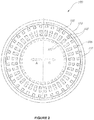
- Figure 2 shows an example of an electric machine 100 described in US Patent No. 7,262,539 , having two independent channel sections which in essence provide two separately controllable machines, namely machine A and machine B, within the same stator structure 102.
- the rotor 104 is shown as being outside the stator 102, but it can be inside if desired.
- the stator 102 has a plurality of stator windings 106 provided in slots 108 of stator 102.
- Permanent magnets 110 are provided on the rotor 104.
- the channels A, B comprise independent and separated sets of windings 106, and thus machine 100 has a two-in-one electric machine design.
- the windings of channel A are confined to the sector of the stator indicated as "A" in Figure 2
- the windings of channel B are confined to the sector of the stator indicated as “B” in Figure 2
- the windings are independently operable by a controller, and may be operated each in a motor and generator mode. For example, rotation of rotor 104 may be used to generate electricity in the windings 106 of channel A, while the windings of channel B are turned “off” via the control coils 107 effect on the magnetic properties of the stator sector. Alternately, the windings of channel B may also be turned “on” and also used to generate electricity in tandem with the windings of channel A.
- the control of the relevant stator, using DC current in the control winding is useful for both controlling the generator mode of the machine and the motor mode of the machine.
- the DC control current controls the AC output current from the windings as is described in US patent 7,262,539 .
- the control current is normally held at a fixed value unless a fault is detected in either the relevant motor winding or in the relevant motor drive circuit, at which point the control current would be set to zero and the relevant motor drive would be shut off, preventing current generated by the continued rotation of the machine from circulating in the fault circuit.
- the non-failed motor/motor drive channel is used to continue the rotation of the machine to drive the accessories, while repairs / replacement would be made at the next earliest opportunity.
- the electric machine 10 may be standard or have a dual redundant configuration.
- One exemplary dual redundant configuration is a single stator dual rotor configuration. Other dual redundant configurations may also be applicable, as will be understood by those skilled in the art.
- the electric machine 10 may also have more than two channels by providing a single rotor rotating relative to multiple independent stators. In the case of dual channels, the rotor rotates relative to a first "virtual" stator and also relative to a second "virtual” stator. The electric machine 10 is thus a "two-in-one" machine in this case. The output of these two “machines” may then be combined, which permits the option of operating the "two machines" as one.
- the machine 10 may be single or multi-phase.
- the windings may have single or multi turns per slot, the number of turns of windings does not have to equal the number of turns of control windings, the number of turns of a winding does not necessarily have to be a whole number, the number of primary windings does not have to equal the number of control windings, as one or more windings in a slot may perhaps be present in another slot.
- a variety of winding types may be used (squirrel cage, lap, etc.), and the windings may be any conductor(s) (i.e. single conductor, more than one wire, insulated, laminated, etc.) or may be superconductors.
- multiphase machine there may be zigzag, delta, or Y-connected windings in accordance with known techniques. There need not be an air gap between the primary and control winding, as long as the windings are electrically isolated from one another.
- FIG. 3 there is illustrated an exemplary starting system 200 for a twin engine installation, incorporating the electric machine 10 described above.
- two electric machines 10 operate as starter-generators 210, 212 and comprises a single rotor 201 dual stator 203 configuration.
- the starter-generators 210, 212 are used for starting the engines and also generating electricity when the engines are in operation.
- Two separate sets of stator windings (Stator A, Stator B) 203 are used to drive a common rotor 201 in each starter-generator 210, 212.
- the two stators 203 each output electricity via their respective sets of windings during the generation mode of operation.
- the dual channel single rotor starter-generators 210, 212 are controlled by a respective dual channel full authority digital engine control (FADEC) 206, 208 via respective dual channel power control units (PCU A, PCU B) 202, 211.
- the FADECs 206, 208 may comprise an electronic engine controller (EEC) or engine control unit (ECU) and its related accessories in order to control all aspects of engine starting performance.
- EEC electronic engine controller
- ECU engine control unit
- the dual FADECs 206, 208 control the input current to both starter channels of the starter-generators 210, 212 based on any one of a number of input parameters, such as speed, temperature, altitude, and forward speed.
- the FADEC may also control the phase angle of the switching sequence to the motor as a function of speed as a means to compensate for phase errors in the motor system
- the starter-generator 210, dual FADEC 206 and dual channel PCU 202 form a first engine arrangement for starting the first engine of the twin engine installation.
- the starter-generator 212, dual FADEC 208 and dual channel PCU 211 form a second engine arrangement for starting the second engine of the twin engine installation.
- An energy storage unit 205 is coupled to both the first engine arrangement and the second engine arrangement.
- the energy storage unit 205 comprises at least a first super-capacitor and a second super-capacitor. More than two super-capacitors may be provided in the energy storage unit 205.
- the two super-capacitors are electrical double-layer capacitors (EDLC A, EDLC B).
- the Boostcap® ultra capacitor from Maxwell Technologies (datasheet BMOD0094 P075 B02) with a rated voltage of 75V may be used.
- Other types of super-capacitors include pseudo-capacitors and hybrid capacitors.
- a single DC to DC converter 207 receives a first voltage level from a power source 216 and increases the first voltage level to a second voltage level.
- the power source 216 may take various forms, such as a single battery, a combination of multiple batteries, a ground power supply, an engine driven generator, and a rotor driven generator.
- the super-capacitors are then charged to the second voltage level by the DC to DC converter 207. This allows the super-capacitors in the energy storage unit 205 to be charged to a higher voltage than is typically available from an aircraft starting supply. For example, the super-capacitors may be charged to approximately 72V from a 28V aircraft supply using a 28V to 72V inverter as the DC to DC converter 207.
- Charging may take place over an extended period of time, and maintaining the charge on the super-capacitors requires a relatively small amount of energy once the initial charge is completed.
- the super-capacitors may continue to receive charging current during the starting process, if desired. Since the charging rate can be orders of magnitude slower than the discharging rate during an engine start, the power source 216 can provide power via a single DC to DC converter 207 at a rate which optimizes battery efficiency (in the case of a battery) in terms of its discharge curve. This may allow many more starts from a battery of a given capacity. This may also allow a smaller, and thus lighter, battery to be used.
- Each super-capacitor may then be used as a high voltage source to provide power to one of the engine arrangements, for starting the first engine and/or the second engine, up to above an idle engine speed.
- Each super-capacitor of the energy storage unit 205 may be connected directly to one of the engine arrangements, or alternatively, a switching module, comprising switches 209, 213, may be used to selectively connect the super-capacitors to a desired one of the two engine arrangements, thus making the super-capacitors interchangeable and capable of starting either one of the engines.
- the super-capacitors may be connected to the engine arrangements via the dual channel PCUs 202, 211 instead of directly into the starter-generators 210, 212.
- an alternate or backup power source 215 may also be provided.
- This power source 215 may be any independent power source and may also be used to feed the energy storage unit 205, for the purposes of charging, recharging, and/or maintaining a charge thereon. It may also be provided simply as a redundant power source in case of failure of the primary power source 216.
- the alternate power source 215 may be, for example, an airframe supplied, transmission mounted generator operating at 3.6KW, 72V, and 50A. Other types of power sources may also be used.
- Figure 3 allows the optimization of the starting speed and acceleration profile, which improves the starting of a gas turbine engine. Dual redundant starting capabilities are also provided for single engine starting. In addition, both engines of the twin engine installation may be started simultaneously, if desired.
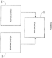
- the starting system 200 is used in conjunction with an ignition system 300 to start one or both of the twin engines 400.
- the ignition system 300 is a continuous plasma ignition system, as described in US Patent No. 5,587,630 .
- the ignition starting system may be incorporated directly into the first engine arrangement and the second engine arrangement, such that a separate continuous plasma ignition system is used for lighting each one of the engines in the twin engine installation.
- a single continuous plasma ignition system is used for both engine arrangements, in a switchable configuration.
- the ignition system 300 comprises a dual redundant configuration, similarly to the starting system 200.
- dual ignition exciters, dual air gap ignitors and dual sets of electrically shielded cables to interface the exciters are provided for each ignition system 300.
- an ignition system 300 with dual redundant configuration is provided for each engine arrangement 210, 212.
- one dual redundant ignition system is switchable between the first engine arrangement 210 and the second engine arrangement 212.
- FIG. 5 illustrates an exemplary method of starting at least one engine of a twin engine installation having a first engine arrangement and a second engine arrangement.
- each engine arrangement may comprise, but does not require, an electric machine with a single rotor dual stator configuration operating as a starter-generator, a dual channel PCU, and a dual FADEC.
- a first voltage level is received from a first power source.
- the first voltage level is increased to a second voltage 504 and used to charge an energy storage unit with at least two electrically separate super-capacitors 506.
- At least one of the two super-capacitors is selectively connected to the PCU of one of the engine arrangements 508 and current is controllably discharged through the PCU to the electric machine 510. At least one of the twin engines is thus started by rotating a rotor of the electric machine to an above engine idle speed 512.
- the first voltage level may be received from any one of a single battery, a plurality of batteries, a ground power supply, an engine driven generator, and a rotor driven generator. Should it be desired to use the second super-capacitor to start the first engine, it may be switched from the second engine arrangement to the first engine arrangement.
- Figure 6 illustrates an exemplary method for concurrently starting both engines of a twin engine installation.
- the method may also comprise a step of recharging/maintaining the charge on the energy storage unit 505. This may be done by the DC to DC converter or by the alternative or backup power source.
- the engine(s) may also be lit using one or more of the respective continuous plasma ignition systems 507.
- the present embodiments may be provided by a combination of hardware and software components, with some components being implemented by a given function or operation of a hardware or software system, and some of the data paths illustrated being implemented by data communication within a computer application or operating system.
- the power control units 202, 211 may be implemented using hardwired logic, Field-Programmable Gate Arrays (FPGAs), analog systems, etc. The structure illustrated is thus provided for efficiency of teaching of the present embodiment, which can be carried out as a method or embodied in a system.
Landscapes
- Engineering & Computer Science (AREA)
- Power Engineering (AREA)
- Chemical & Material Sciences (AREA)
- Combustion & Propulsion (AREA)
- Mechanical Engineering (AREA)
- General Engineering & Computer Science (AREA)
- Control Of Eletrric Generators (AREA)
- Hybrid Electric Vehicles (AREA)
- Electric Propulsion And Braking For Vehicles (AREA)
Applications Claiming Priority (2)
| Application Number | Priority Date | Filing Date | Title |
|---|---|---|---|
| US13/803,572 US9840997B2 (en) | 2013-03-14 | 2013-03-14 | Engine starting system using stored energy |
| EP14159211.3A EP2779427B1 (fr) | 2013-03-14 | 2014-03-12 | Système de démarrage de moteur à l'aide d'une énergie stockée |
Related Parent Applications (1)
| Application Number | Title | Priority Date | Filing Date |
|---|---|---|---|
| EP14159211.3A Division EP2779427B1 (fr) | 2013-03-14 | 2014-03-12 | Système de démarrage de moteur à l'aide d'une énergie stockée |
Publications (2)
| Publication Number | Publication Date |
|---|---|
| EP3447905A1 true EP3447905A1 (fr) | 2019-02-27 |
| EP3447905B1 EP3447905B1 (fr) | 2021-02-17 |
Family
ID=50287889
Family Applications (2)
| Application Number | Title | Priority Date | Filing Date |
|---|---|---|---|
| EP14159211.3A Active EP2779427B1 (fr) | 2013-03-14 | 2014-03-12 | Système de démarrage de moteur à l'aide d'une énergie stockée |
| EP18201630.3A Active EP3447905B1 (fr) | 2013-03-14 | 2014-03-12 | Système de démarrage de moteur à l'aide d'une énergie stockée |
Family Applications Before (1)
| Application Number | Title | Priority Date | Filing Date |
|---|---|---|---|
| EP14159211.3A Active EP2779427B1 (fr) | 2013-03-14 | 2014-03-12 | Système de démarrage de moteur à l'aide d'une énergie stockée |
Country Status (3)
| Country | Link |
|---|---|
| US (3) | US9840997B2 (fr) |
| EP (2) | EP2779427B1 (fr) |
| CA (1) | CA2845185C (fr) |
Families Citing this family (15)
| Publication number | Priority date | Publication date | Assignee | Title |
|---|---|---|---|---|
| US9657645B2 (en) * | 2013-02-25 | 2017-05-23 | Pratt & Whitney Canada Corp. | Engine architecture using electric machine |
| FR3019219B1 (fr) * | 2014-03-27 | 2016-03-18 | Turbomeca | Architecture d'un systeme propulsif d'un helicoptere multi-moteur et helicoptere correspondant |
| US10450886B2 (en) | 2015-12-22 | 2019-10-22 | General Electric Company | Hybrid propulsion system including a chemically rechargeable ultra-capacitor |
| US10598047B2 (en) | 2016-02-29 | 2020-03-24 | United Technologies Corporation | Low-power bowed rotor prevention system |
| US10787933B2 (en) * | 2016-06-20 | 2020-09-29 | Raytheon Technologies Corporation | Low-power bowed rotor prevention and monitoring system |
| US10823078B2 (en) * | 2017-06-28 | 2020-11-03 | General Electric Company | Systems and methods for starting a turbine engine |
| GB2570475B (en) * | 2018-01-26 | 2020-04-08 | Rolls Royce Plc | Cabin blower system |
| US11401041B2 (en) | 2018-07-30 | 2022-08-02 | Raytheon Technologies Corporation | Hybrid electric power distribution and control for an aircraft |
| US11565821B2 (en) | 2018-07-30 | 2023-01-31 | Raytheon Technologies Corporation | Hybrid energy storage system control for an aircraft engine |
| US11332256B2 (en) | 2018-08-21 | 2022-05-17 | General Electric Company | Fault tolerant hybrid electric propulsion system for an aerial vehicle |
| US11015480B2 (en) | 2018-08-21 | 2021-05-25 | General Electric Company | Feed forward load sensing for hybrid electric systems |
| US11027719B2 (en) | 2018-12-03 | 2021-06-08 | General Electric Company | Distributed power generation for a vehicle system |
| US11286805B2 (en) * | 2020-06-22 | 2022-03-29 | Florida Turbine Technologies, Inc. | Multi-spool geared turbofan arrangement with integrated starter/generator |
| GB202118041D0 (en) * | 2021-12-14 | 2022-01-26 | Rolls Royce Plc | Restarting a gas turbine engine |
| FR3143231A1 (fr) * | 2022-12-07 | 2024-06-14 | Safran Electrical & Power | Système propulsif électrique d’aéronef à tolérance de pannes |
Citations (7)
| Publication number | Priority date | Publication date | Assignee | Title |
|---|---|---|---|---|
| JPH04178144A (ja) * | 1990-08-24 | 1992-06-25 | Satake Eng Co Ltd | 2固定子誘導電動機 |
| US5552681A (en) * | 1992-03-06 | 1996-09-03 | Hino Jidosha Kogyo Kabushiki Kaisha | Apparatus for storing energy generated during breaking of a vehicle and for providing energy to the internal combustion engine of the vehicle at other times |
| US5587630A (en) | 1993-10-28 | 1996-12-24 | Pratt & Whitney Canada Inc. | Continuous plasma ignition system |
| WO1999000596A1 (fr) * | 1997-06-30 | 1999-01-07 | Sundstrand Corporation | Systeme redondant de demarrage/generation |
| US5899411A (en) * | 1996-01-22 | 1999-05-04 | Sundstrand Corporation | Aircraft electrical system providing emergency power and electric starting of propulsion engines |
| US7262539B2 (en) | 2004-11-26 | 2007-08-28 | Pratt & Whitney Canada Corp. | Saturation control of electric machine |
| DE102009057263A1 (de) * | 2009-12-08 | 2011-06-09 | Hofer Eds Gmbh | Start-Stopp-System, insbesondere für ein Kraftfahrzeug mit Verbrennungskraftmaschine |
Family Cites Families (13)
| Publication number | Priority date | Publication date | Assignee | Title |
|---|---|---|---|---|
| FR2769952A1 (fr) * | 1997-10-20 | 1999-04-23 | Aerospatiale | Dispositif de demarrage pour turbine a gaz dans un aeronef |
| US6355987B1 (en) | 2000-06-27 | 2002-03-12 | General Electric Company | Power converter and control for microturbine |
| US6639328B2 (en) | 2000-12-19 | 2003-10-28 | Capstone Turbine Corporation | Microturbine/capacitor power distribution system |
| JP4343691B2 (ja) * | 2001-11-13 | 2009-10-14 | グッドリッチ・ポンプ・アンド・エンジン・コントロール・システムズ・インコーポレーテッド | ガスタービン・エンジン用故障管理システム |
| US7319306B1 (en) * | 2004-06-25 | 2008-01-15 | Sure Power Industries, Inc. | Supercapacitor engine starting system with charge hysteresis |
| US7513119B2 (en) * | 2005-02-03 | 2009-04-07 | The Boeing Company | Systems and methods for starting aircraft engines |
| US7958727B2 (en) | 2005-12-29 | 2011-06-14 | Honeywell International Inc. | Electric boost compressor and turbine generator system |
| US7693264B2 (en) | 2006-11-07 | 2010-04-06 | General Electric Company | Antechamber control reducing leak through ferrofluid seals |
| US7704110B2 (en) | 2007-08-31 | 2010-04-27 | Brp Us Inc. | Engine starting system for a marine outboard engine |
| US7952221B2 (en) * | 2007-11-14 | 2011-05-31 | Honeywell International Inc. | Enhanced DC electric main engine start system |
| US7963264B2 (en) | 2008-06-25 | 2011-06-21 | GM Global Technology Operations LLC | Engine cranking system and method |
| US8164206B2 (en) * | 2009-03-26 | 2012-04-24 | Ford Global Technologies, Llc | Methods and systems for engine start control |
| FR2967132B1 (fr) | 2010-11-04 | 2012-11-09 | Turbomeca | Procede d'optimisation de la consommation specifique d'un helicoptere bimoteur et architecture bimoteur dissymetrique a systeme de regulation pour sa mise en oeuvre |
-
2013
- 2013-03-14 US US13/803,572 patent/US9840997B2/en active Active
-
2014
- 2014-02-28 CA CA2845185A patent/CA2845185C/fr active Active
- 2014-03-12 EP EP14159211.3A patent/EP2779427B1/fr active Active
- 2014-03-12 EP EP18201630.3A patent/EP3447905B1/fr active Active
-
2017
- 2017-11-07 US US15/805,602 patent/US10578071B2/en active Active
-
2020
- 2020-01-24 US US16/751,877 patent/US11391258B2/en active Active
Patent Citations (7)
| Publication number | Priority date | Publication date | Assignee | Title |
|---|---|---|---|---|
| JPH04178144A (ja) * | 1990-08-24 | 1992-06-25 | Satake Eng Co Ltd | 2固定子誘導電動機 |
| US5552681A (en) * | 1992-03-06 | 1996-09-03 | Hino Jidosha Kogyo Kabushiki Kaisha | Apparatus for storing energy generated during breaking of a vehicle and for providing energy to the internal combustion engine of the vehicle at other times |
| US5587630A (en) | 1993-10-28 | 1996-12-24 | Pratt & Whitney Canada Inc. | Continuous plasma ignition system |
| US5899411A (en) * | 1996-01-22 | 1999-05-04 | Sundstrand Corporation | Aircraft electrical system providing emergency power and electric starting of propulsion engines |
| WO1999000596A1 (fr) * | 1997-06-30 | 1999-01-07 | Sundstrand Corporation | Systeme redondant de demarrage/generation |
| US7262539B2 (en) | 2004-11-26 | 2007-08-28 | Pratt & Whitney Canada Corp. | Saturation control of electric machine |
| DE102009057263A1 (de) * | 2009-12-08 | 2011-06-09 | Hofer Eds Gmbh | Start-Stopp-System, insbesondere für ein Kraftfahrzeug mit Verbrennungskraftmaschine |
Also Published As
| Publication number | Publication date |
|---|---|
| US9840997B2 (en) | 2017-12-12 |
| CA2845185C (fr) | 2021-06-01 |
| CA2845185A1 (fr) | 2014-09-14 |
| EP3447905B1 (fr) | 2021-02-17 |
| EP2779427A2 (fr) | 2014-09-17 |
| US11391258B2 (en) | 2022-07-19 |
| EP2779427B1 (fr) | 2018-10-24 |
| US20200166013A1 (en) | 2020-05-28 |
| EP2779427A3 (fr) | 2015-01-14 |
| US20180058412A1 (en) | 2018-03-01 |
| US10578071B2 (en) | 2020-03-03 |
| US20140260306A1 (en) | 2014-09-18 |
Similar Documents
| Publication | Publication Date | Title |
|---|---|---|
| US11391258B2 (en) | Engine starting system using stored energy | |
| US10669950B2 (en) | Engine architecture using electric machine | |
| US12097965B2 (en) | Electric architecture for a hybrid thermal/electric propulsion aircraft and twin-engined aircraft comprising such an architecture | |
| US9776583B2 (en) | Aircraft electrical system | |
| CN112888633B (zh) | 用于飞行器的转换和输送电能的系统 | |
| RU2655183C2 (ru) | Устройство отключения генераторов переменного тока турбомашины во время ускорения | |
| CN105765214B (zh) | 用于起动航空器的发动机的方法 | |
| US20170107910A1 (en) | Method and apparatus for starting an aircraft engine and operating a power architecture for an aircraft | |
| EP4054044B1 (fr) | Systèmes d'alimentation électrique | |
| US20200157966A1 (en) | Engine assembly | |
| US9917544B2 (en) | Method and power converter unit for operating a generator | |
| EP4054040A1 (fr) | Systèmes d'alimentation électrique | |
| EP4054041A1 (fr) | Systèmes d'alimentation électrique | |
| CA3156955C (fr) | Système de contrôle d’huile et de carburant pour moteur et méthode pour contrôler l’huile et le carburant dans un moteur | |
| EP3096448B1 (fr) | Générateur à champ enroulé comprenant un alternateur de moteur isolé électriquement | |
| CN110784048A (zh) | 定子组件 |
Legal Events
| Date | Code | Title | Description |
|---|---|---|---|
| PUAI | Public reference made under article 153(3) epc to a published international application that has entered the european phase |
Free format text: ORIGINAL CODE: 0009012 |
|
| STAA | Information on the status of an ep patent application or granted ep patent |
Free format text: STATUS: THE APPLICATION HAS BEEN PUBLISHED |
|
| AC | Divisional application: reference to earlier application |
Ref document number: 2779427 Country of ref document: EP Kind code of ref document: P |
|
| AK | Designated contracting states |
Kind code of ref document: A1 Designated state(s): AL AT BE BG CH CY CZ DE DK EE ES FI FR GB GR HR HU IE IS IT LI LT LU LV MC MK MT NL NO PL PT RO RS SE SI SK SM TR |
|
| STAA | Information on the status of an ep patent application or granted ep patent |
Free format text: STATUS: REQUEST FOR EXAMINATION WAS MADE |
|
| 17P | Request for examination filed |
Effective date: 20190827 |
|
| RBV | Designated contracting states (corrected) |
Designated state(s): AL AT BE BG CH CY CZ DE DK EE ES FI FR GB GR HR HU IE IS IT LI LT LU LV MC MK MT NL NO PL PT RO RS SE SI SK SM TR |
|
| GRAP | Despatch of communication of intention to grant a patent |
Free format text: ORIGINAL CODE: EPIDOSNIGR1 |
|
| STAA | Information on the status of an ep patent application or granted ep patent |
Free format text: STATUS: GRANT OF PATENT IS INTENDED |
|
| INTG | Intention to grant announced |
Effective date: 20200812 |
|
| RIN1 | Information on inventor provided before grant (corrected) |
Inventor name: PEKOVIC, TATJANA |
|
| GRAS | Grant fee paid |
Free format text: ORIGINAL CODE: EPIDOSNIGR3 |
|
| GRAA | (expected) grant |
Free format text: ORIGINAL CODE: 0009210 |
|
| STAA | Information on the status of an ep patent application or granted ep patent |
Free format text: STATUS: THE PATENT HAS BEEN GRANTED |
|
| AC | Divisional application: reference to earlier application |
Ref document number: 2779427 Country of ref document: EP Kind code of ref document: P |
|
| AK | Designated contracting states |
Kind code of ref document: B1 Designated state(s): AL AT BE BG CH CY CZ DE DK EE ES FI FR GB GR HR HU IE IS IT LI LT LU LV MC MK MT NL NO PL PT RO RS SE SI SK SM TR |
|
| REG | Reference to a national code |
Ref country code: GB Ref legal event code: FG4D |
|
| REG | Reference to a national code |
Ref country code: CH Ref legal event code: EP |
|
| REG | Reference to a national code |
Ref country code: DE Ref legal event code: R096 Ref document number: 602014075030 Country of ref document: DE |
|
| REG | Reference to a national code |
Ref country code: AT Ref legal event code: REF Ref document number: 1362826 Country of ref document: AT Kind code of ref document: T Effective date: 20210315 |
|
| REG | Reference to a national code |
Ref country code: IE Ref legal event code: FG4D |
|
| REG | Reference to a national code |
Ref country code: LT Ref legal event code: MG9D |
|
| REG | Reference to a national code |
Ref country code: NL Ref legal event code: MP Effective date: 20210217 |
|
| PG25 | Lapsed in a contracting state [announced via postgrant information from national office to epo] |
Ref country code: FI Free format text: LAPSE BECAUSE OF FAILURE TO SUBMIT A TRANSLATION OF THE DESCRIPTION OR TO PAY THE FEE WITHIN THE PRESCRIBED TIME-LIMIT Effective date: 20210217 Ref country code: GR Free format text: LAPSE BECAUSE OF FAILURE TO SUBMIT A TRANSLATION OF THE DESCRIPTION OR TO PAY THE FEE WITHIN THE PRESCRIBED TIME-LIMIT Effective date: 20210518 Ref country code: HR Free format text: LAPSE BECAUSE OF FAILURE TO SUBMIT A TRANSLATION OF THE DESCRIPTION OR TO PAY THE FEE WITHIN THE PRESCRIBED TIME-LIMIT Effective date: 20210217 Ref country code: BG Free format text: LAPSE BECAUSE OF FAILURE TO SUBMIT A TRANSLATION OF THE DESCRIPTION OR TO PAY THE FEE WITHIN THE PRESCRIBED TIME-LIMIT Effective date: 20210517 Ref country code: NO Free format text: LAPSE BECAUSE OF FAILURE TO SUBMIT A TRANSLATION OF THE DESCRIPTION OR TO PAY THE FEE WITHIN THE PRESCRIBED TIME-LIMIT Effective date: 20210517 Ref country code: PT Free format text: LAPSE BECAUSE OF FAILURE TO SUBMIT A TRANSLATION OF THE DESCRIPTION OR TO PAY THE FEE WITHIN THE PRESCRIBED TIME-LIMIT Effective date: 20210617 Ref country code: LT Free format text: LAPSE BECAUSE OF FAILURE TO SUBMIT A TRANSLATION OF THE DESCRIPTION OR TO PAY THE FEE WITHIN THE PRESCRIBED TIME-LIMIT Effective date: 20210217 |
|
| REG | Reference to a national code |
Ref country code: AT Ref legal event code: MK05 Ref document number: 1362826 Country of ref document: AT Kind code of ref document: T Effective date: 20210217 |
|
| PG25 | Lapsed in a contracting state [announced via postgrant information from national office to epo] |
Ref country code: SE Free format text: LAPSE BECAUSE OF FAILURE TO SUBMIT A TRANSLATION OF THE DESCRIPTION OR TO PAY THE FEE WITHIN THE PRESCRIBED TIME-LIMIT Effective date: 20210217 Ref country code: PL Free format text: LAPSE BECAUSE OF FAILURE TO SUBMIT A TRANSLATION OF THE DESCRIPTION OR TO PAY THE FEE WITHIN THE PRESCRIBED TIME-LIMIT Effective date: 20210217 Ref country code: NL Free format text: LAPSE BECAUSE OF FAILURE TO SUBMIT A TRANSLATION OF THE DESCRIPTION OR TO PAY THE FEE WITHIN THE PRESCRIBED TIME-LIMIT Effective date: 20210217 Ref country code: LV Free format text: LAPSE BECAUSE OF FAILURE TO SUBMIT A TRANSLATION OF THE DESCRIPTION OR TO PAY THE FEE WITHIN THE PRESCRIBED TIME-LIMIT Effective date: 20210217 Ref country code: RS Free format text: LAPSE BECAUSE OF FAILURE TO SUBMIT A TRANSLATION OF THE DESCRIPTION OR TO PAY THE FEE WITHIN THE PRESCRIBED TIME-LIMIT Effective date: 20210217 |
|
| PG25 | Lapsed in a contracting state [announced via postgrant information from national office to epo] |
Ref country code: IS Free format text: LAPSE BECAUSE OF FAILURE TO SUBMIT A TRANSLATION OF THE DESCRIPTION OR TO PAY THE FEE WITHIN THE PRESCRIBED TIME-LIMIT Effective date: 20210617 |
|
| PG25 | Lapsed in a contracting state [announced via postgrant information from national office to epo] |
Ref country code: EE Free format text: LAPSE BECAUSE OF FAILURE TO SUBMIT A TRANSLATION OF THE DESCRIPTION OR TO PAY THE FEE WITHIN THE PRESCRIBED TIME-LIMIT Effective date: 20210217 Ref country code: CZ Free format text: LAPSE BECAUSE OF FAILURE TO SUBMIT A TRANSLATION OF THE DESCRIPTION OR TO PAY THE FEE WITHIN THE PRESCRIBED TIME-LIMIT Effective date: 20210217 Ref country code: SM Free format text: LAPSE BECAUSE OF FAILURE TO SUBMIT A TRANSLATION OF THE DESCRIPTION OR TO PAY THE FEE WITHIN THE PRESCRIBED TIME-LIMIT Effective date: 20210217 Ref country code: AT Free format text: LAPSE BECAUSE OF FAILURE TO SUBMIT A TRANSLATION OF THE DESCRIPTION OR TO PAY THE FEE WITHIN THE PRESCRIBED TIME-LIMIT Effective date: 20210217 |
|
| REG | Reference to a national code |
Ref country code: CH Ref legal event code: PL |
|
| REG | Reference to a national code |
Ref country code: DE Ref legal event code: R097 Ref document number: 602014075030 Country of ref document: DE |
|
| PG25 | Lapsed in a contracting state [announced via postgrant information from national office to epo] |
Ref country code: DK Free format text: LAPSE BECAUSE OF FAILURE TO SUBMIT A TRANSLATION OF THE DESCRIPTION OR TO PAY THE FEE WITHIN THE PRESCRIBED TIME-LIMIT Effective date: 20210217 Ref country code: RO Free format text: LAPSE BECAUSE OF FAILURE TO SUBMIT A TRANSLATION OF THE DESCRIPTION OR TO PAY THE FEE WITHIN THE PRESCRIBED TIME-LIMIT Effective date: 20210217 Ref country code: SK Free format text: LAPSE BECAUSE OF FAILURE TO SUBMIT A TRANSLATION OF THE DESCRIPTION OR TO PAY THE FEE WITHIN THE PRESCRIBED TIME-LIMIT Effective date: 20210217 Ref country code: MC Free format text: LAPSE BECAUSE OF FAILURE TO SUBMIT A TRANSLATION OF THE DESCRIPTION OR TO PAY THE FEE WITHIN THE PRESCRIBED TIME-LIMIT Effective date: 20210217 |
|
| REG | Reference to a national code |
Ref country code: BE Ref legal event code: MM Effective date: 20210331 |
|
| PLBE | No opposition filed within time limit |
Free format text: ORIGINAL CODE: 0009261 |
|
| STAA | Information on the status of an ep patent application or granted ep patent |
Free format text: STATUS: NO OPPOSITION FILED WITHIN TIME LIMIT |
|
| 26N | No opposition filed |
Effective date: 20211118 |
|
| PG25 | Lapsed in a contracting state [announced via postgrant information from national office to epo] |
Ref country code: ES Free format text: LAPSE BECAUSE OF FAILURE TO SUBMIT A TRANSLATION OF THE DESCRIPTION OR TO PAY THE FEE WITHIN THE PRESCRIBED TIME-LIMIT Effective date: 20210217 Ref country code: AL Free format text: LAPSE BECAUSE OF FAILURE TO SUBMIT A TRANSLATION OF THE DESCRIPTION OR TO PAY THE FEE WITHIN THE PRESCRIBED TIME-LIMIT Effective date: 20210217 Ref country code: CH Free format text: LAPSE BECAUSE OF NON-PAYMENT OF DUE FEES Effective date: 20210331 Ref country code: LI Free format text: LAPSE BECAUSE OF NON-PAYMENT OF DUE FEES Effective date: 20210331 Ref country code: LU Free format text: LAPSE BECAUSE OF NON-PAYMENT OF DUE FEES Effective date: 20210312 Ref country code: IE Free format text: LAPSE BECAUSE OF NON-PAYMENT OF DUE FEES Effective date: 20210312 |
|
| PG25 | Lapsed in a contracting state [announced via postgrant information from national office to epo] |
Ref country code: SI Free format text: LAPSE BECAUSE OF FAILURE TO SUBMIT A TRANSLATION OF THE DESCRIPTION OR TO PAY THE FEE WITHIN THE PRESCRIBED TIME-LIMIT Effective date: 20210217 |
|
| PG25 | Lapsed in a contracting state [announced via postgrant information from national office to epo] |
Ref country code: IT Free format text: LAPSE BECAUSE OF FAILURE TO SUBMIT A TRANSLATION OF THE DESCRIPTION OR TO PAY THE FEE WITHIN THE PRESCRIBED TIME-LIMIT Effective date: 20210217 |
|
| PG25 | Lapsed in a contracting state [announced via postgrant information from national office to epo] |
Ref country code: IS Free format text: LAPSE BECAUSE OF FAILURE TO SUBMIT A TRANSLATION OF THE DESCRIPTION OR TO PAY THE FEE WITHIN THE PRESCRIBED TIME-LIMIT Effective date: 20210617 |
|
| PG25 | Lapsed in a contracting state [announced via postgrant information from national office to epo] |
Ref country code: BE Free format text: LAPSE BECAUSE OF NON-PAYMENT OF DUE FEES Effective date: 20210331 |
|
| PG25 | Lapsed in a contracting state [announced via postgrant information from national office to epo] |
Ref country code: CY Free format text: LAPSE BECAUSE OF FAILURE TO SUBMIT A TRANSLATION OF THE DESCRIPTION OR TO PAY THE FEE WITHIN THE PRESCRIBED TIME-LIMIT Effective date: 20210217 |
|
| P01 | Opt-out of the competence of the unified patent court (upc) registered |
Effective date: 20230530 |
|
| PG25 | Lapsed in a contracting state [announced via postgrant information from national office to epo] |
Ref country code: HU Free format text: LAPSE BECAUSE OF FAILURE TO SUBMIT A TRANSLATION OF THE DESCRIPTION OR TO PAY THE FEE WITHIN THE PRESCRIBED TIME-LIMIT; INVALID AB INITIO Effective date: 20140312 |
|
| PG25 | Lapsed in a contracting state [announced via postgrant information from national office to epo] |
Ref country code: MK Free format text: LAPSE BECAUSE OF FAILURE TO SUBMIT A TRANSLATION OF THE DESCRIPTION OR TO PAY THE FEE WITHIN THE PRESCRIBED TIME-LIMIT Effective date: 20210217 |
|
| PG25 | Lapsed in a contracting state [announced via postgrant information from national office to epo] |
Ref country code: MT Free format text: LAPSE BECAUSE OF FAILURE TO SUBMIT A TRANSLATION OF THE DESCRIPTION OR TO PAY THE FEE WITHIN THE PRESCRIBED TIME-LIMIT Effective date: 20210217 |
|
| PG25 | Lapsed in a contracting state [announced via postgrant information from national office to epo] |
Ref country code: TR Free format text: LAPSE BECAUSE OF FAILURE TO SUBMIT A TRANSLATION OF THE DESCRIPTION OR TO PAY THE FEE WITHIN THE PRESCRIBED TIME-LIMIT Effective date: 20210217 |
|
| PGFP | Annual fee paid to national office [announced via postgrant information from national office to epo] |
Ref country code: GB Payment date: 20260219 Year of fee payment: 13 |
|
| PGFP | Annual fee paid to national office [announced via postgrant information from national office to epo] |
Ref country code: DE Payment date: 20260219 Year of fee payment: 13 |
|
| PGFP | Annual fee paid to national office [announced via postgrant information from national office to epo] |
Ref country code: FR Payment date: 20260220 Year of fee payment: 13 |