EP3448121A1 - Dispositif d'alimentation de micro-ondes sur un four à micro-ondes - Google Patents
Dispositif d'alimentation de micro-ondes sur un four à micro-ondes Download PDFInfo
- Publication number
- EP3448121A1 EP3448121A1 EP17187390.4A EP17187390A EP3448121A1 EP 3448121 A1 EP3448121 A1 EP 3448121A1 EP 17187390 A EP17187390 A EP 17187390A EP 3448121 A1 EP3448121 A1 EP 3448121A1
- Authority
- EP
- European Patent Office
- Prior art keywords
- coupling
- cooking chamber
- power
- coupling element
- waveguide
- Prior art date
- Legal status (The legal status is an assumption and is not a legal conclusion. Google has not performed a legal analysis and makes no representation as to the accuracy of the status listed.)
- Granted
Links
Images


Classifications
-
- H—ELECTRICITY
- H05—ELECTRIC TECHNIQUES NOT OTHERWISE PROVIDED FOR
- H05B—ELECTRIC HEATING; ELECTRIC LIGHT SOURCES NOT OTHERWISE PROVIDED FOR; CIRCUIT ARRANGEMENTS FOR ELECTRIC LIGHT SOURCES, IN GENERAL
- H05B6/00—Heating by electric, magnetic or electromagnetic fields
- H05B6/64—Heating using microwaves
- H05B6/66—Circuits
- H05B6/68—Circuits for monitoring or control
-
- H—ELECTRICITY
- H05—ELECTRIC TECHNIQUES NOT OTHERWISE PROVIDED FOR
- H05B—ELECTRIC HEATING; ELECTRIC LIGHT SOURCES NOT OTHERWISE PROVIDED FOR; CIRCUIT ARRANGEMENTS FOR ELECTRIC LIGHT SOURCES, IN GENERAL
- H05B6/00—Heating by electric, magnetic or electromagnetic fields
- H05B6/64—Heating using microwaves
- H05B6/70—Feed lines
- H05B6/707—Feed lines using waveguides
-
- F—MECHANICAL ENGINEERING; LIGHTING; HEATING; WEAPONS; BLASTING
- F24—HEATING; RANGES; VENTILATING
- F24C—DOMESTIC STOVES OR RANGES ; DETAILS OF DOMESTIC STOVES OR RANGES, OF GENERAL APPLICATION
- F24C7/00—Stoves or ranges heated by electric energy
- F24C7/06—Arrangement or mounting of electric heating elements
- F24C7/067—Arrangement or mounting of electric heating elements on ranges
-
- H—ELECTRICITY
- H05—ELECTRIC TECHNIQUES NOT OTHERWISE PROVIDED FOR
- H05B—ELECTRIC HEATING; ELECTRIC LIGHT SOURCES NOT OTHERWISE PROVIDED FOR; CIRCUIT ARRANGEMENTS FOR ELECTRIC LIGHT SOURCES, IN GENERAL
- H05B6/00—Heating by electric, magnetic or electromagnetic fields
- H05B6/64—Heating using microwaves
- H05B6/70—Feed lines
- H05B6/705—Feed lines using microwave tuning
Definitions
- the invention relates to a device for feeding an alternating electromagnetic field generated by a microwave transmitter in a cooking chamber of a microwave oven, wherein the alternating electromagnetic field is transmitted in a power flow direction by means of a transmission device from the microwave transmitter to a plurality of feed points of the cooking chamber, where the electromagnetic power generated by the microwave transmitter in the Cooking chamber is fed, wherein the transmission device has at least one waveguide and a coupled to the waveguide coupling element.
- the invention further relates to a method for operating such a device.
- microwave ovens Devices for feeding electromagnetic alternating fields in a cooking chamber are known under the name "microwave ovens".
- the electromagnetic alternating field is generated by a microwave transmitter having a magnetron for this purpose.
- the microwaves are transmitted via a decoupling section to a coupling element.
- the coupling element couples the electromagnetic alternating field to a waveguide, which opens into the cooking chamber.
- the coupling element and the decoupling section can form an impedance converter.
- the electromagnetic waves prepare in the direction of their emission direction at the feed points and are reflected several times by the walls. There is no homogeneous field distribution within the Cooking space, so that the heating of food inside the cooking chamber is not homogeneous. Standing waves arising in the cooking chamber are superimposed destructively or constructively. There remain hot or cold spots.
- the EP 0 284 958 A1 proposes a device for coupling a microwave field to a microwave oven, in which coupling pins are provided within a resonator chamber, which are to cause a rotation of the coupled into the resonator cavity electromagnetic field, so that can emerge from an infeed unpolarized alternating field. There is also proposed to connect two transmitters, each with a waveguide to a common resonator, which in turn is coupled via a plurality of coupling openings to the cooking chamber.
- the invention has for its object to propose measures with which the food to be heated is heated more uniformly and thus has a more homogeneous temperature distribution.
- the transmission device with which the electromagnetic alternating field and thus the power generated by the microwave transmitter is transmitted from the microwave transmitter to the feed points, has a coupling element and a plurality of waveguides.
- the alternating electromagnetic field is fed into the coupling element and divided with his help on several waveguides, so that it can be passed in several different ways in the oven, since each waveguide opens at an individually assigned feed point into the cooking chamber.
- the electromagnetic alternating field is generated, for example, in a magnetron and, for example, fed into a coupling branch of the coupling element.
- the coupling element may have a plurality of outcoupling branches which divide the power fed into the coupling element into the plurality of waveguides. This can be done according to a predetermined power sharing ratio.
- the power coupled in the coupling branch is transmitted uniformly to all the coupling branches.
- the coupling element may be formed by an electrically conductive body, in particular by a metal body. It can be a multi-armed pen. An arm of the coupling element acts as a coupling branch. Several other arms of the coupling element act as decoupling branches.
- the coupling element forms a switch, with which electromagnetic waves generated by a single source can be distributed to a plurality of outputs. Each output is preferably assigned an entry point.
- the feed points are preferably arranged on at least two mutually angled walls of the cooking chamber.
- this embodiment which in particular has a plurality of lateral feed points, it is possible to influence the constructive and destructive superimpositions which occur in the prior art and arise from a superposition of the field strengths in such a way that the electromagnetic waves essentially do not cancel each other out 100 percent additively superimpose, so that can be reduced with the inventive device, the formation of cold and hot zones within the food.
- the coupling element is designed as a multi-way switch.
- the individual coupling-out branches can also be brought from a power-transmitting functional position into a non-power-transmitting functional position with respect to the coupling branch.
- This makes it possible to feed the power through different feed points into the cooking chamber in a time sequence, wherein in particular it is also provided that the electromagnetic alternating fields are fed successively through different groups of feed points in the cooking chamber.
- the feed points can be realized through openings, at each of which a waveguide opens into the cooking chamber. As a result, individual zones or radiation paths within the cooking chamber can be supplied with microwave energy in chronological succession.
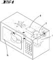
- FIG. 1 shows a microwave oven according to the prior art, in which a housing limited by walls cooking chamber 14 is provided within a housing, in which at a feed point, a waveguide 8 opens in the power in the form of an alternating electromagnetic field is coupled.
- the electromagnetic alternating field is generated in a magnetron 1 and coupled via a decoupling section 2 in the waveguide 8.
- Within the cooking chamber 14 there is a multiple reflection of the propagating alternating electromagnetic field.
- the energy transported by the electromagnetic alternating field is converted into heat within the food.
- a paddle wheel is arranged on the ceiling of the cooking chamber 14.
- FIG. 2 shows a further microwave oven of the prior art, in which the alternating electromagnetic field generated by a microwave transmitter 1, 2 is coupled into a coupling element 3 in the form of a coupling pin.
- the coupling element 3 transmits the electromagnetic power generated by the microwave transmitter 1, 2 to a waveguide 8, in which the power is transported as electromagnetic radiation to an opening in the wall of the cooking chamber 14, which constitutes a feed point 11.
- the in the FIG. 3 illustrated first embodiment of the invention has a coupling element 3, which is fork-shaped. It has four Poor.
- a short Einkopplungsarm 4 which branches into three outcoupling arms 5, 6, 7.
- the coupled into the Einkopplungsarm 4 electromagnetic power is uniformly in the outcoupling arms 5, 6, 7 protrude.
- the ends of the outcoupling arms 5, 6, 7 form local sources for an electromagnetic alternating field, which is in each case transmitted to a waveguide 8, 9,10.
- the waveguides 8, 9,10 open at mutually different locations in the cooking chamber 14.
- the waveguides 8, 9,10 open at three lying in a side wall at different points infeed points 11, 12, 13th
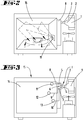
- FIGS. 4 and 5 show a further embodiment in which the coupling element 3 is also formed as a total four-armed coupling pin.
- a Einkopplungsarm 4 is connected to a plurality of outcoupling arms 5, 6, 7.
- Each output arm 5, 6, 7 is connected to a waveguide 8, 9, 10.
- the waveguide 8 opens on a side wall of the cooking chamber 14 in its upper region and forms a feed point 11 from.
- the waveguide 9 opens on the back of the cooking chamber 14 at a feed point 12.
- the waveguide 10 opens below the feed point 11 of the waveguide 8 at a feed point 13 in the cooking chamber fourteenth
- the total of three outcoupling branches 5, 6, 7, which are connected together with a coupling branch 4, are selectively brought from a power transmitting functional position in a non-power transmitting functional position.
- suitable switching means 16,17,18 are provided, with which the power transmission from the coupling end of the coupling-out branch 5, 6, 7 for auskoppelnden end of the coupling-out branch 5, 6, 7 can be interrupted.
- electromagnetic alternating fields can be coupled into the cooking chamber 14 at spatially different feed-in points 11, 12, 13. These may be polarized or non-polarized alternating electromagnetic fields.
- the feed points 11,12,13 are arranged at selected locations of the walls of the cooking chamber 14, that the electromagnetic waves are superimposed neither 100 percent constructive nor 100 percent destructive.
- electromagnetic alternating fields can be fed into the cooking chamber 14 at different feed-in points 11, 12, 13 in chronologically successive steps. It is also possible to use different groups of feed points 11, 12, 13 for feeding the heating power.
- the coupling element 3 may be an electrically conductive solid in which electromagnetic microwaves are fed.
- the solid bifurcates into several outcoupling branches 5, 6, 7. This branch divides the microwaves into several outputs.
- the coupling-out branches 5, 6, 7 are preferably each connected to a waveguide 8, 9, 10, which conduct the microwaves to the feed-in points 11, 12, 13.
- the coupling element 3 may also be physically different. Essential is its electrical property, divided into a coupling branch 4 coupled power to several outcoupling branches 5, 6, 7.
- the coupling element 3 can thus also be formed as a branching waveguide.
- Each coupling branch 5, 6, 7 can in a Pass over waveguide 8, which opens at the feed point 11, 12, 13 in the cooking chamber 14.
- the switching elements denoted by the reference numerals 16, 17, 18 can block the power transmission through a coupling-out branch 5, 6, 7. However, it is also possible to merely reduce the power transmission through a coupling-out branch 5, 6, 7, so that the electromagnetic power coupled into the coupling branch 4 can be transmitted in varying ratios to the coupling-out branches 5, 6, 7.
Landscapes
- Physics & Mathematics (AREA)
- Electromagnetism (AREA)
- Engineering & Computer Science (AREA)
- Chemical & Material Sciences (AREA)
- Combustion & Propulsion (AREA)
- Mechanical Engineering (AREA)
- General Engineering & Computer Science (AREA)
- Constitution Of High-Frequency Heating (AREA)
- Electric Ovens (AREA)
Priority Applications (5)
| Application Number | Priority Date | Filing Date | Title |
|---|---|---|---|
| EP17187390.4A EP3448121B1 (fr) | 2017-08-23 | 2017-08-23 | Dispositif d'alimentation de micro-ondes sur un four à micro-ondes |
| ES17187390T ES2844648T3 (es) | 2017-08-23 | 2017-08-23 | Dispositivo de alimentación de microondas en un horno de microondas |
| PL17187390T PL3448121T3 (pl) | 2017-08-23 | 2017-08-23 | Urządzenie zasilające mikrofalami w kuchence mikrofalowej |
| US16/108,586 US20190069354A1 (en) | 2017-08-23 | 2018-08-22 | Microwave feed device on a microwave oven |
| CN201810959000.2A CN109429401A (zh) | 2017-08-23 | 2018-08-22 | 在微波炉上的微波馈入设备 |
Applications Claiming Priority (1)
| Application Number | Priority Date | Filing Date | Title |
|---|---|---|---|
| EP17187390.4A EP3448121B1 (fr) | 2017-08-23 | 2017-08-23 | Dispositif d'alimentation de micro-ondes sur un four à micro-ondes |
Publications (2)
| Publication Number | Publication Date |
|---|---|
| EP3448121A1 true EP3448121A1 (fr) | 2019-02-27 |
| EP3448121B1 EP3448121B1 (fr) | 2020-12-23 |
Family
ID=59745715
Family Applications (1)
| Application Number | Title | Priority Date | Filing Date |
|---|---|---|---|
| EP17187390.4A Active EP3448121B1 (fr) | 2017-08-23 | 2017-08-23 | Dispositif d'alimentation de micro-ondes sur un four à micro-ondes |
Country Status (5)
| Country | Link |
|---|---|
| US (1) | US20190069354A1 (fr) |
| EP (1) | EP3448121B1 (fr) |
| CN (1) | CN109429401A (fr) |
| ES (1) | ES2844648T3 (fr) |
| PL (1) | PL3448121T3 (fr) |
Citations (5)
| Publication number | Priority date | Publication date | Assignee | Title |
|---|---|---|---|---|
| FR1378280A (fr) * | 1963-10-04 | 1964-11-13 | Procédé et dispositif d'excitation d'un four de chauffage à ondes d'hyperfréquence | |
| EP0284958A1 (fr) | 1987-03-24 | 1988-10-05 | Gigatherm Aktiengesellschaft | Dispositif de couplage d'un champ à micro-ondes à un four à micro-ondes |
| JP2008269794A (ja) * | 2007-04-16 | 2008-11-06 | Matsushita Electric Ind Co Ltd | マイクロ波処理装置 |
| EP2445312A1 (fr) * | 2010-10-22 | 2012-04-25 | Whirlpool Corporation | Appareil de chauffage par micro-ondes et son procédé de fonctionnement |
| EP3151636A1 (fr) * | 2014-05-28 | 2017-04-05 | Guangdong Midea Kitchen Appliances Manufacturing Co., Ltd. | Four à micro-ondes à semi-conducteur et source de micro-ondes à semi-conducteur pour celui-ci |
Family Cites Families (9)
| Publication number | Priority date | Publication date | Assignee | Title |
|---|---|---|---|---|
| SE387815B (sv) * | 1974-12-18 | 1976-09-13 | Husqvarna Ab | Mikrovagsapplikator |
| DE4027777A1 (de) * | 1990-09-01 | 1992-03-05 | Kueppersbusch | Mikrowellenofen |
| CN1826026A (zh) * | 2005-02-24 | 2006-08-30 | 厦门灿坤实业股份有限公司 | 均匀辐射的微波加热方法及装置 |
| CN101282600B (zh) * | 2007-04-06 | 2010-09-15 | 财团法人食品工业发展研究所 | 连续式微波加热装置 |
| CN102374557B (zh) * | 2011-10-31 | 2016-08-03 | 广东美的厨房电器制造有限公司 | 半导体微波炉的微波馈入结构 |
| CN109068430B (zh) * | 2012-03-14 | 2022-05-24 | 微波材料技术有限公司 | 微波加热系统及其使用方法 |
| CN104676670A (zh) * | 2014-05-28 | 2015-06-03 | 广东美的厨房电器制造有限公司 | 半导体微波炉及其半导体微波源 |
| CN104902604B (zh) * | 2015-06-08 | 2016-11-30 | 广东美的厨房电器制造有限公司 | 波导组件和微波饭煲 |
| CN109417836B (zh) * | 2016-12-27 | 2021-04-16 | 惠而浦公司 | 固态射频发生系统和电磁烹饪装置 |
-
2017
- 2017-08-23 ES ES17187390T patent/ES2844648T3/es active Active
- 2017-08-23 EP EP17187390.4A patent/EP3448121B1/fr active Active
- 2017-08-23 PL PL17187390T patent/PL3448121T3/pl unknown
-
2018
- 2018-08-22 CN CN201810959000.2A patent/CN109429401A/zh active Pending
- 2018-08-22 US US16/108,586 patent/US20190069354A1/en not_active Abandoned
Patent Citations (5)
| Publication number | Priority date | Publication date | Assignee | Title |
|---|---|---|---|---|
| FR1378280A (fr) * | 1963-10-04 | 1964-11-13 | Procédé et dispositif d'excitation d'un four de chauffage à ondes d'hyperfréquence | |
| EP0284958A1 (fr) | 1987-03-24 | 1988-10-05 | Gigatherm Aktiengesellschaft | Dispositif de couplage d'un champ à micro-ondes à un four à micro-ondes |
| JP2008269794A (ja) * | 2007-04-16 | 2008-11-06 | Matsushita Electric Ind Co Ltd | マイクロ波処理装置 |
| EP2445312A1 (fr) * | 2010-10-22 | 2012-04-25 | Whirlpool Corporation | Appareil de chauffage par micro-ondes et son procédé de fonctionnement |
| EP3151636A1 (fr) * | 2014-05-28 | 2017-04-05 | Guangdong Midea Kitchen Appliances Manufacturing Co., Ltd. | Four à micro-ondes à semi-conducteur et source de micro-ondes à semi-conducteur pour celui-ci |
Also Published As
| Publication number | Publication date |
|---|---|
| US20190069354A1 (en) | 2019-02-28 |
| EP3448121B1 (fr) | 2020-12-23 |
| PL3448121T3 (pl) | 2021-06-14 |
| CN109429401A (zh) | 2019-03-05 |
| ES2844648T3 (es) | 2021-07-22 |
Similar Documents
| Publication | Publication Date | Title |
|---|---|---|
| DE1027274B (de) | Leiter zur UEbertragung elektromagnetischer H-Wellen | |
| DE102007035357B4 (de) | Antennenstruktur für ein Gargerät und Gargerät mit solch einer Antennenstruktur | |
| DE69106942T2 (de) | Vorrichtung zur Speisung von Strahlungselementen einer Gruppenantenne und ihre Verwendung für eine Antenne eines Landungshilfssystems vom Typ MLS. | |
| DE10139071A1 (de) | Wandlervorrichtung | |
| DE1909092A1 (de) | Hybridkoppler mit 90 deg.-Phasenverschiebung | |
| DE2058485C3 (de) | Anordnung für die Umschaltung und Verteilung von Hochfrequenz-Energie | |
| DE2830855A1 (de) | Matrix aus kopplungsnetzwerken und daraus aufgebaute antennenanordnung | |
| EP3448121A1 (fr) | Dispositif d'alimentation de micro-ondes sur un four à micro-ondes | |
| DE112010002639B4 (de) | Antenneneinrichtung | |
| DE1264545C2 (de) | Verteilerschaltung fuer vier im Drehfeld gespeiste Strahler | |
| DE1276764B (de) | Hochfrequenzverteiler | |
| DE102013220254A1 (de) | Hochfrequenzschaltung mit gekreuzten Leitungen | |
| DE102012210852A1 (de) | Kochfeld bzw. Gargerät mit einem Kochfeld und einer elektrischen Versorgungsleitung | |
| DE102022131525A1 (de) | Verstärkerschaltung für Mikrowellensignale sowie Mikrowellenvorrichtung | |
| DE570167C (de) | Heizbares Antennensystem | |
| EP1253669B1 (fr) | Réseau d'antennes avec un nombre d' éléments rayonnants résonants | |
| DE2423112C2 (de) | Anordnung zur Aufteilung von Hochfrequenzenergie auf zwei oder mehr Verbraucherausgänge | |
| DE757273C (de) | Anordnung zur Anpassung einer Hochfrequenzleitung an eine Belastung | |
| DE2323143C3 (de) | Sammelschieneneinrichtung, insbesondere für Gemeinschaftsantennenanlagen | |
| DE2525741B2 (de) | Taktimpulssystem mit einem Impulsgenerator zum Erzeugen und mit Verteilerleitungen zum Verteilen zweier zueinander symmetrischer und zeitlich verschobener Taktimpulssignale | |
| DE102022131522A1 (de) | Verstärkerschaltung für Mikrowellensignale sowie Gargerät | |
| DE1591163C (de) | Vorrichtung zur Addition von Mikrowel lensignalen | |
| DE102023133248A1 (de) | Verstärkerschaltung mit phasenverschiebenden Elementen für Mikrowellensignale sowie Gargerät | |
| DE1956812C (de) | Abgleichbarer Anpassungs-Speiseleitungs-Abschnitt für die Übertragung von Ultrakurz- oder Mikrowellen | |
| WO2025228785A1 (fr) | Procédé de réglage d'une distribution de puissance haute fréquence, coupleur hybride à commande de phase, système coupleur hybride et agencement de coupleur hybride |
Legal Events
| Date | Code | Title | Description |
|---|---|---|---|
| PUAI | Public reference made under article 153(3) epc to a published international application that has entered the european phase |
Free format text: ORIGINAL CODE: 0009012 |
|
| STAA | Information on the status of an ep patent application or granted ep patent |
Free format text: STATUS: THE APPLICATION HAS BEEN PUBLISHED |
|
| AK | Designated contracting states |
Kind code of ref document: A1 Designated state(s): AL AT BE BG CH CY CZ DE DK EE ES FI FR GB GR HR HU IE IS IT LI LT LU LV MC MK MT NL NO PL PT RO RS SE SI SK SM TR |
|
| AX | Request for extension of the european patent |
Extension state: BA ME |
|
| STAA | Information on the status of an ep patent application or granted ep patent |
Free format text: STATUS: REQUEST FOR EXAMINATION WAS MADE |
|
| 17P | Request for examination filed |
Effective date: 20190731 |
|
| RBV | Designated contracting states (corrected) |
Designated state(s): AL AT BE BG CH CY CZ DE DK EE ES FI FR GB GR HR HU IE IS IT LI LT LU LV MC MK MT NL NO PL PT RO RS SE SI SK SM TR |
|
| GRAP | Despatch of communication of intention to grant a patent |
Free format text: ORIGINAL CODE: EPIDOSNIGR1 |
|
| STAA | Information on the status of an ep patent application or granted ep patent |
Free format text: STATUS: GRANT OF PATENT IS INTENDED |
|
| INTG | Intention to grant announced |
Effective date: 20200717 |
|
| GRAS | Grant fee paid |
Free format text: ORIGINAL CODE: EPIDOSNIGR3 |
|
| GRAA | (expected) grant |
Free format text: ORIGINAL CODE: 0009210 |
|
| STAA | Information on the status of an ep patent application or granted ep patent |
Free format text: STATUS: THE PATENT HAS BEEN GRANTED |
|
| AK | Designated contracting states |
Kind code of ref document: B1 Designated state(s): AL AT BE BG CH CY CZ DE DK EE ES FI FR GB GR HR HU IE IS IT LI LT LU LV MC MK MT NL NO PL PT RO RS SE SI SK SM TR |
|
| REG | Reference to a national code |
Ref country code: GB Ref legal event code: FG4D Free format text: NOT ENGLISH |
|
| REG | Reference to a national code |
Ref country code: DE Ref legal event code: R096 Ref document number: 502017008746 Country of ref document: DE |
|
| REG | Reference to a national code |
Ref country code: AT Ref legal event code: REF Ref document number: 1348961 Country of ref document: AT Kind code of ref document: T Effective date: 20210115 |
|
| REG | Reference to a national code |
Ref country code: IE Ref legal event code: FG4D Free format text: LANGUAGE OF EP DOCUMENT: GERMAN |
|
| PG25 | Lapsed in a contracting state [announced via postgrant information from national office to epo] |
Ref country code: GR Free format text: LAPSE BECAUSE OF FAILURE TO SUBMIT A TRANSLATION OF THE DESCRIPTION OR TO PAY THE FEE WITHIN THE PRESCRIBED TIME-LIMIT Effective date: 20210324 Ref country code: FI Free format text: LAPSE BECAUSE OF FAILURE TO SUBMIT A TRANSLATION OF THE DESCRIPTION OR TO PAY THE FEE WITHIN THE PRESCRIBED TIME-LIMIT Effective date: 20201223 Ref country code: RS Free format text: LAPSE BECAUSE OF FAILURE TO SUBMIT A TRANSLATION OF THE DESCRIPTION OR TO PAY THE FEE WITHIN THE PRESCRIBED TIME-LIMIT Effective date: 20201223 Ref country code: NO Free format text: LAPSE BECAUSE OF FAILURE TO SUBMIT A TRANSLATION OF THE DESCRIPTION OR TO PAY THE FEE WITHIN THE PRESCRIBED TIME-LIMIT Effective date: 20210323 |
|
| REG | Reference to a national code |
Ref country code: NL Ref legal event code: MP Effective date: 20201223 |
|
| PG25 | Lapsed in a contracting state [announced via postgrant information from national office to epo] |
Ref country code: SE Free format text: LAPSE BECAUSE OF FAILURE TO SUBMIT A TRANSLATION OF THE DESCRIPTION OR TO PAY THE FEE WITHIN THE PRESCRIBED TIME-LIMIT Effective date: 20201223 Ref country code: BG Free format text: LAPSE BECAUSE OF FAILURE TO SUBMIT A TRANSLATION OF THE DESCRIPTION OR TO PAY THE FEE WITHIN THE PRESCRIBED TIME-LIMIT Effective date: 20210323 Ref country code: LV Free format text: LAPSE BECAUSE OF FAILURE TO SUBMIT A TRANSLATION OF THE DESCRIPTION OR TO PAY THE FEE WITHIN THE PRESCRIBED TIME-LIMIT Effective date: 20201223 |
|
| PG25 | Lapsed in a contracting state [announced via postgrant information from national office to epo] |
Ref country code: NL Free format text: LAPSE BECAUSE OF FAILURE TO SUBMIT A TRANSLATION OF THE DESCRIPTION OR TO PAY THE FEE WITHIN THE PRESCRIBED TIME-LIMIT Effective date: 20201223 Ref country code: HR Free format text: LAPSE BECAUSE OF FAILURE TO SUBMIT A TRANSLATION OF THE DESCRIPTION OR TO PAY THE FEE WITHIN THE PRESCRIBED TIME-LIMIT Effective date: 20201223 |
|
| REG | Reference to a national code |
Ref country code: LT Ref legal event code: MG9D |
|
| REG | Reference to a national code |
Ref country code: ES Ref legal event code: FG2A Ref document number: 2844648 Country of ref document: ES Kind code of ref document: T3 Effective date: 20210722 |
|
| PG25 | Lapsed in a contracting state [announced via postgrant information from national office to epo] |
Ref country code: SK Free format text: LAPSE BECAUSE OF FAILURE TO SUBMIT A TRANSLATION OF THE DESCRIPTION OR TO PAY THE FEE WITHIN THE PRESCRIBED TIME-LIMIT Effective date: 20201223 Ref country code: RO Free format text: LAPSE BECAUSE OF FAILURE TO SUBMIT A TRANSLATION OF THE DESCRIPTION OR TO PAY THE FEE WITHIN THE PRESCRIBED TIME-LIMIT Effective date: 20201223 Ref country code: PT Free format text: LAPSE BECAUSE OF FAILURE TO SUBMIT A TRANSLATION OF THE DESCRIPTION OR TO PAY THE FEE WITHIN THE PRESCRIBED TIME-LIMIT Effective date: 20210423 Ref country code: EE Free format text: LAPSE BECAUSE OF FAILURE TO SUBMIT A TRANSLATION OF THE DESCRIPTION OR TO PAY THE FEE WITHIN THE PRESCRIBED TIME-LIMIT Effective date: 20201223 Ref country code: CZ Free format text: LAPSE BECAUSE OF FAILURE TO SUBMIT A TRANSLATION OF THE DESCRIPTION OR TO PAY THE FEE WITHIN THE PRESCRIBED TIME-LIMIT Effective date: 20201223 Ref country code: SM Free format text: LAPSE BECAUSE OF FAILURE TO SUBMIT A TRANSLATION OF THE DESCRIPTION OR TO PAY THE FEE WITHIN THE PRESCRIBED TIME-LIMIT Effective date: 20201223 Ref country code: LT Free format text: LAPSE BECAUSE OF FAILURE TO SUBMIT A TRANSLATION OF THE DESCRIPTION OR TO PAY THE FEE WITHIN THE PRESCRIBED TIME-LIMIT Effective date: 20201223 |
|
| REG | Reference to a national code |
Ref country code: DE Ref legal event code: R097 Ref document number: 502017008746 Country of ref document: DE |
|
| PG25 | Lapsed in a contracting state [announced via postgrant information from national office to epo] |
Ref country code: IS Free format text: LAPSE BECAUSE OF FAILURE TO SUBMIT A TRANSLATION OF THE DESCRIPTION OR TO PAY THE FEE WITHIN THE PRESCRIBED TIME-LIMIT Effective date: 20210423 |
|
| PG25 | Lapsed in a contracting state [announced via postgrant information from national office to epo] |
Ref country code: AL Free format text: LAPSE BECAUSE OF FAILURE TO SUBMIT A TRANSLATION OF THE DESCRIPTION OR TO PAY THE FEE WITHIN THE PRESCRIBED TIME-LIMIT Effective date: 20201223 |
|
| PLBE | No opposition filed within time limit |
Free format text: ORIGINAL CODE: 0009261 |
|
| STAA | Information on the status of an ep patent application or granted ep patent |
Free format text: STATUS: NO OPPOSITION FILED WITHIN TIME LIMIT |
|
| PG25 | Lapsed in a contracting state [announced via postgrant information from national office to epo] |
Ref country code: DK Free format text: LAPSE BECAUSE OF FAILURE TO SUBMIT A TRANSLATION OF THE DESCRIPTION OR TO PAY THE FEE WITHIN THE PRESCRIBED TIME-LIMIT Effective date: 20201223 |
|
| 26N | No opposition filed |
Effective date: 20210924 |
|
| PG25 | Lapsed in a contracting state [announced via postgrant information from national office to epo] |
Ref country code: SI Free format text: LAPSE BECAUSE OF FAILURE TO SUBMIT A TRANSLATION OF THE DESCRIPTION OR TO PAY THE FEE WITHIN THE PRESCRIBED TIME-LIMIT Effective date: 20201223 |
|
| PG25 | Lapsed in a contracting state [announced via postgrant information from national office to epo] |
Ref country code: MC Free format text: LAPSE BECAUSE OF FAILURE TO SUBMIT A TRANSLATION OF THE DESCRIPTION OR TO PAY THE FEE WITHIN THE PRESCRIBED TIME-LIMIT Effective date: 20201223 |
|
| REG | Reference to a national code |
Ref country code: BE Ref legal event code: MM Effective date: 20210831 |
|
| PG25 | Lapsed in a contracting state [announced via postgrant information from national office to epo] |
Ref country code: IS Free format text: LAPSE BECAUSE OF FAILURE TO SUBMIT A TRANSLATION OF THE DESCRIPTION OR TO PAY THE FEE WITHIN THE PRESCRIBED TIME-LIMIT Effective date: 20210423 Ref country code: LU Free format text: LAPSE BECAUSE OF NON-PAYMENT OF DUE FEES Effective date: 20210823 |
|
| PG25 | Lapsed in a contracting state [announced via postgrant information from national office to epo] |
Ref country code: IE Free format text: LAPSE BECAUSE OF NON-PAYMENT OF DUE FEES Effective date: 20210823 Ref country code: BE Free format text: LAPSE BECAUSE OF NON-PAYMENT OF DUE FEES Effective date: 20210831 |
|
| P01 | Opt-out of the competence of the unified patent court (upc) registered |
Effective date: 20230517 |
|
| PG25 | Lapsed in a contracting state [announced via postgrant information from national office to epo] |
Ref country code: CY Free format text: LAPSE BECAUSE OF FAILURE TO SUBMIT A TRANSLATION OF THE DESCRIPTION OR TO PAY THE FEE WITHIN THE PRESCRIBED TIME-LIMIT Effective date: 20201223 |
|
| PG25 | Lapsed in a contracting state [announced via postgrant information from national office to epo] |
Ref country code: HU Free format text: LAPSE BECAUSE OF FAILURE TO SUBMIT A TRANSLATION OF THE DESCRIPTION OR TO PAY THE FEE WITHIN THE PRESCRIBED TIME-LIMIT; INVALID AB INITIO Effective date: 20170823 |
|
| REG | Reference to a national code |
Ref country code: AT Ref legal event code: MM01 Ref document number: 1348961 Country of ref document: AT Kind code of ref document: T Effective date: 20220823 |
|
| PG25 | Lapsed in a contracting state [announced via postgrant information from national office to epo] |
Ref country code: AT Free format text: LAPSE BECAUSE OF NON-PAYMENT OF DUE FEES Effective date: 20220823 |
|
| PG25 | Lapsed in a contracting state [announced via postgrant information from national office to epo] |
Ref country code: MK Free format text: LAPSE BECAUSE OF FAILURE TO SUBMIT A TRANSLATION OF THE DESCRIPTION OR TO PAY THE FEE WITHIN THE PRESCRIBED TIME-LIMIT Effective date: 20201223 |
|
| PG25 | Lapsed in a contracting state [announced via postgrant information from national office to epo] |
Ref country code: TR Free format text: LAPSE BECAUSE OF FAILURE TO SUBMIT A TRANSLATION OF THE DESCRIPTION OR TO PAY THE FEE WITHIN THE PRESCRIBED TIME-LIMIT Effective date: 20201223 |
|
| PG25 | Lapsed in a contracting state [announced via postgrant information from national office to epo] |
Ref country code: MT Free format text: LAPSE BECAUSE OF FAILURE TO SUBMIT A TRANSLATION OF THE DESCRIPTION OR TO PAY THE FEE WITHIN THE PRESCRIBED TIME-LIMIT Effective date: 20201223 |
|
| PGFP | Annual fee paid to national office [announced via postgrant information from national office to epo] |
Ref country code: ES Payment date: 20250917 Year of fee payment: 9 |
|
| PGFP | Annual fee paid to national office [announced via postgrant information from national office to epo] |
Ref country code: DE Payment date: 20250819 Year of fee payment: 9 |
|
| PGFP | Annual fee paid to national office [announced via postgrant information from national office to epo] |
Ref country code: PL Payment date: 20250808 Year of fee payment: 9 Ref country code: IT Payment date: 20250829 Year of fee payment: 9 |
|
| PGFP | Annual fee paid to national office [announced via postgrant information from national office to epo] |
Ref country code: GB Payment date: 20250818 Year of fee payment: 9 |
|
| PGFP | Annual fee paid to national office [announced via postgrant information from national office to epo] |
Ref country code: FR Payment date: 20250821 Year of fee payment: 9 |
|
| PGFP | Annual fee paid to national office [announced via postgrant information from national office to epo] |
Ref country code: CH Payment date: 20250901 Year of fee payment: 9 |