EP3448121B1 - Dispositif d'alimentation de micro-ondes sur un four à micro-ondes - Google Patents
Dispositif d'alimentation de micro-ondes sur un four à micro-ondes Download PDFInfo
- Publication number
- EP3448121B1 EP3448121B1 EP17187390.4A EP17187390A EP3448121B1 EP 3448121 B1 EP3448121 B1 EP 3448121B1 EP 17187390 A EP17187390 A EP 17187390A EP 3448121 B1 EP3448121 B1 EP 3448121B1
- Authority
- EP
- European Patent Office
- Prior art keywords
- coupling
- power
- coupling element
- branch
- waveguide
- Prior art date
- Legal status (The legal status is an assumption and is not a legal conclusion. Google has not performed a legal analysis and makes no representation as to the accuracy of the status listed.)
- Active
Links
Images

Classifications
-
- H—ELECTRICITY
- H05—ELECTRIC TECHNIQUES NOT OTHERWISE PROVIDED FOR
- H05B—ELECTRIC HEATING; ELECTRIC LIGHT SOURCES NOT OTHERWISE PROVIDED FOR; CIRCUIT ARRANGEMENTS FOR ELECTRIC LIGHT SOURCES, IN GENERAL
- H05B6/00—Heating by electric, magnetic or electromagnetic fields
- H05B6/64—Heating using microwaves
- H05B6/66—Circuits
- H05B6/68—Circuits for monitoring or control
-
- H—ELECTRICITY
- H05—ELECTRIC TECHNIQUES NOT OTHERWISE PROVIDED FOR
- H05B—ELECTRIC HEATING; ELECTRIC LIGHT SOURCES NOT OTHERWISE PROVIDED FOR; CIRCUIT ARRANGEMENTS FOR ELECTRIC LIGHT SOURCES, IN GENERAL
- H05B6/00—Heating by electric, magnetic or electromagnetic fields
- H05B6/64—Heating using microwaves
- H05B6/70—Feed lines
- H05B6/707—Feed lines using waveguides
-
- F—MECHANICAL ENGINEERING; LIGHTING; HEATING; WEAPONS; BLASTING
- F24—HEATING; RANGES; VENTILATING
- F24C—DOMESTIC STOVES OR RANGES ; DETAILS OF DOMESTIC STOVES OR RANGES, OF GENERAL APPLICATION
- F24C7/00—Stoves or ranges heated by electric energy
- F24C7/06—Arrangement or mounting of electric heating elements
- F24C7/067—Arrangement or mounting of electric heating elements on ranges
-
- H—ELECTRICITY
- H05—ELECTRIC TECHNIQUES NOT OTHERWISE PROVIDED FOR
- H05B—ELECTRIC HEATING; ELECTRIC LIGHT SOURCES NOT OTHERWISE PROVIDED FOR; CIRCUIT ARRANGEMENTS FOR ELECTRIC LIGHT SOURCES, IN GENERAL
- H05B6/00—Heating by electric, magnetic or electromagnetic fields
- H05B6/64—Heating using microwaves
- H05B6/70—Feed lines
- H05B6/705—Feed lines using microwave tuning
Definitions
- the invention relates to a device for feeding an electromagnetic alternating field generated by a microwave transmitter into a cooking chamber of a microwave oven, the electromagnetic alternating field being transmitted in one power flow direction by means of a transmission device from the microwave transmitter to a plurality of feed points in the cooking chamber, at which the electromagnetic power generated by the microwave transmitter enters the Cooking chamber is fed, the transmission device having at least one waveguide and a coupling element coupled to the waveguide, the coupling element designed as a power distributor connecting the microwave transmitter to a plurality of waveguides.
- the invention also relates to a method for operating such a device.
- microwave ovens Devices for feeding alternating electromagnetic fields into a cooking space are known as "microwave ovens".
- the electromagnetic alternating field is generated by a microwave transmitter which has a magnetron for this purpose.
- the microwaves are transmitted to a coupling element via a coupling-out section.
- the coupling element couples the electromagnetic alternating field to a waveguide which opens into the cooking space.
- the coupling element and the decoupling section can form an impedance converter.
- the electromagnetic waves spread out in the direction of their emission at the feed points and are released several times from the walls reflected. There is no homogeneous field distribution within the cooking space, so that the heating of food within the cooking space is not homogeneous. Standing waves that arise in the cooking space are destructively or constructively superimposed. There remain hot or cold spots.
- the EP 0 284 958 A1 proposes a device for coupling a microwave field to a microwave oven, in which coupling pins are provided within a resonator chamber which are intended to cause a rotation of the electromagnetic field coupled into the resonator chamber so that unpolarized alternating field can emerge from a feed opening. It is also proposed there to connect two transmitters, each with a waveguide, to a common resonator chamber, which in turn is coupled to the cooking chamber via several coupling openings.
- Microwave ovens are known in which an electromagnetic alternating field is transmitted by means of a transmission device from a microwave transmitter to several feed points of the cooking chamber, the transmission device having a waveguide and a coupling element coupled to it, which coupling element in turn connects the microwave transmitter with several waveguides.
- the invention is based on the object of proposing measures with which the food to be heated is heated more evenly and thus has a more homogeneous temperature distribution.
- the transmission device with which the electromagnetic alternating field and thus the power generated by the microwave transmitter is transmitted from the microwave transmitter to the feed points has a coupling element and several waveguides, the coupling element being a coupling pin having several arms.
- the electromagnetic alternating field is fed into the coupling element and, with its help, divided over several waveguides, so that it can be conducted into the cooking chamber in several different ways, since each waveguide opens into the cooking chamber at an individually assigned feed point.
- the electromagnetic alternating field is, for example, also generated in a magnetron and fed into a coupling branch of the coupling element, for example.
- the coupling element can have several decoupling branches which divide the power fed into the coupling element to the several waveguides. This can take place in accordance with a predetermined power sharing ratio.
- the power coupled into the coupling branch is preferably transmitted uniformly to all coupling branches.
- the coupling element can be formed from an electrically conductive body, in particular from a metal body.
- One arm of the coupling element acts as a coupling branch.
- Several other arms of the coupling element act as decoupling branches.
- the coupling element forms a switch with which electromagnetic waves generated by a single source are distributed to several outputs can.
- a feed point is preferably assigned to each output.
- the feed points are preferably arranged on at least two walls of the cooking chamber that are at an angle to one another.
- the device according to the invention can reduce the formation of cold and hot zones within the food to be cooked.
- the coupling element is designed as a multi-way switch.
- the individual decoupling branches can also be brought from a power-transmitting functional position into a non-power-transmitting functional position with respect to the coupling-in branch.
- This makes it possible to feed the power into the cooking chamber through different feed points in a chronological sequence, whereby it is also provided in particular that the alternating electromagnetic fields are fed into the cooking chamber one after the other through different groups of feed points.
- the feed points can be realized through openings, at each of which a waveguide opens into the cooking space. As a result, individual zones or radiation paths within the cooking space can be supplied with microwave energy one after the other in a time-controlled manner.
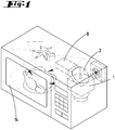
- the Figure 1 shows a microwave oven according to the prior art, in which a wall-bounded cooking space 14 is provided within a housing, into which a waveguide 8 opens at a feed point, into which power is coupled in the form of an electromagnetic alternating field.
- the electromagnetic alternating field is generated in a magnetron 1 and is coupled into the waveguide 8 via a decoupling section 2.
- a multiple reflection of the propagating electromagnetic alternating field takes place within the cooking chamber 14.
- the energy transported with the electromagnetic alternating field is converted into heat within the food.
- a paddle wheel is arranged on the ceiling of the cooking chamber 14 to homogenize the field distribution.
- the Figure 2 shows a further microwave oven of the prior art, in which the electromagnetic alternating field generated by a microwave transmitter 1, 2 is coupled into a coupling element 3 in the form of a coupling pin.
- the coupling element 3 transmits the electromagnetic power generated by the microwave transmitter 1, 2 to a waveguide 8, in which the power is transported as electromagnetic radiation to an opening in the wall of the cooking chamber 14, which represents a feed point 11.
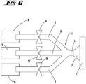
- the illustrated first embodiment of the invention has a coupling element 3 which is fork-shaped. It has four arms.
- a short coupling arm 4 which branches into three coupling arms 5, 6, 7.
- the electromagnetic power coupled into the coupling arm 4 will project evenly into the coupling arms 5, 6, 7.
- the ends of the decoupling arms 5, 6, 7 form local sources for an electromagnetic alternating field, which is transmitted to a waveguide 8, 9, 10 in each case.
- the waveguides 8, 9, 10 open into the cooking chamber 14 at different locations Figure 3
- the illustrated embodiment, the waveguides 8, 9, 10 open at three feed points 11, 12, 13 located in a side wall at different points.
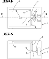
- the Figures 4 and 5 show a further embodiment in which the coupling element 3 is also designed as a four-armed coupling pin.
- a coupling arm 4 is connected to a plurality of decoupling arms 5, 6, 7.
- Each decoupling arm 5, 6, 7 is connected to a waveguide 8, 9, 10.
- the waveguide 8 opens out on a side wall of the cooking space 14 in its upper region and forms a feed point 11.
- the waveguide 9 opens out on the rear side of the cooking chamber 14 at a feed point 12.
- the waveguide 10 opens below the feed point 11 of the waveguide 8 at a feed point 13 into the cooking space 14.
- the total of three decoupling branches 5, 6, 7, which are connected together with an in-coupling branch 4, can optionally be brought from a power-transmitting functional position to a non-power-transmitting functional position.
- suitable switching means 16, 17, 18 are provided with which the power transmission from the coupling-in end of the coupling-out branch 5, 6, 7 to the coupling-out end of the coupling-out branch 5, 6, 7 can be interrupted.
- alternating electromagnetic fields can be coupled into the cooking chamber 14 at spatially different feed points 11, 12, 13. It can be polarized or non-polarized alternating electromagnetic fields.
- the feed points 11, 12, 13 are arranged at selected points on the walls of the cooking chamber 14 in such a way that the electromagnetic waves are superimposed neither 100 percent constructively nor 100 percent destructively.
- electromagnetic alternating fields can be fed into the cooking chamber 14 at different feed points 11, 12, 13 in successive steps. It is also possible to use different groups of feed points 11, 12, 13 for feeding in the heating power.
- the coupling element 3 can be an electrically conductive solid body into which electromagnetic microwaves are fed will.
- the solid forks into several decoupling branches 5, 6, 7. Through this branching, the microwaves are divided into several outputs.
- the decoupling branches 5, 6, 7 are preferably each connected to a waveguide 8, 9, 10, which guide the microwaves to the feed points 11, 12, 13.
- the coupling element 3 can, however, also have a different physical design. What is essential is its electrotechnical property of dividing power coupled into a coupling branch 4 over several coupling branches 5, 6, 7.
- the coupling element 3 can thus also be designed as a branching waveguide. Each decoupling branch 5, 6, 7 can merge into a waveguide 8 which opens into the cooking chamber 14 at the feed point 11, 12, 13.
- the switching elements identified by the reference numbers 16, 17, 18 can block the power transmission through a decoupling branch 5, 6, 7. However, it is also possible to merely reduce the power transmission through a decoupling branch 5, 6, 7, so that the electromagnetic power coupled into the coupling branch 4 can be transmitted to the decoupling branches 5, 6, 7 in varying proportions.
Landscapes
- Physics & Mathematics (AREA)
- Electromagnetism (AREA)
- Engineering & Computer Science (AREA)
- Chemical & Material Sciences (AREA)
- Combustion & Propulsion (AREA)
- Mechanical Engineering (AREA)
- General Engineering & Computer Science (AREA)
- Constitution Of High-Frequency Heating (AREA)
- Electric Ovens (AREA)
Claims (9)
- Dispositif pour l'introduction d'un champ électromagnétique alternatif généré par un émetteur de micro-ondes (1, 2) dans une chambre de cuisson (14) d'un four à micro-ondes, dans lequel le champ électromagnétique alternatif est transmis au moyen d'un dispositif de transmission dans une direction de flux de puissance de l'émetteur de micro-ondes (1, 2) à plusieurs points d'introduction (11, 12, 13) de la chambre de cuisson (14) auxquels la puissance générée par l'émetteur à micro-ondes (1, 2) est introduite dans la chambre de cuisson (14), dans lequel le dispositif de transmission présente au moins un guide d'ondes (8, 9, 10) et un élément de couplage (3) couplé au guide d'ondes (8, 9, 10), dans lequel l'élément de couplage (3) conçu comme un distributeur de puissance relie l'émetteur de micro-ondes (1, 2) à plusieurs guides d'ondes (8, 9, 10), caractérisé en ce que l'élément de couplage (3) est une broche de couplage présentant plusieurs bras.
- Dispositif selon la revendication 1, caractérisé en ce que l'élément de couplage (3) comprend une branche de couplage d'entrée (4) dans laquelle est injecté le champ électromagnétique alternatif et plusieurs branches de couplage de sortie (5, 6, 7) auxquelles est distribuée la puissance introduite dans la branche de couplage d'entrée (4).
- Dispositif selon la revendication 2, caractérisé en ce que la puissance électromagnétique injectée dans la branche de couplage d'entrée (4) est distribuée de manière sensiblement uniforme à la pluralité de branches de couplage de sortie (5, 6, 7) .
- Dispositif selon la revendication 2 ou 3, caractérisé en ce que chaque branche de couplage de sortie (5, 6, 7), en particulier chaque branche de couplage de sortie (5, 6, 7) conçue comme un bras, est reliée de manière opérationnelle à un guide d'ondes (8, 9, 10) qui lui est individuellement associé.
- Dispositif selon l'une des revendications précédentes, caractérisé en ce que les points d'introduction (11, 12, 13) sont agencés sur au moins deux parois de la chambre de cuisson (14) qui sont distinctes l'une de l'autre.
- Dispositif selon l'une des revendications 2 à 5, caractérisé par des éléments de commutation (16, 17, 18) avec lesquels les branches de couplage de sortie (5, 6, 7) peuvent être amenées individuellement d'une position fonctionnelle de transmission de puissance vis-à-vis de la branche de couplage d'entrée (4) à une position fonctionnelle de non-transmission de puissance vis-à-vis de la branche de couplage d'entrée (4).
- Dispositif selon la revendication 6, caractérisé en ce que les éléments de commutation (16, 17, 18) sont conçus de telle manière que les puissances sorties via les branches de couplage de sortie (5, 6, 7) peuvent être variées.
- Procédé pour faire fonctionner un dispositif selon l'une des revendications précédentes, dans lequel la puissance électromagnétique générée par l'émetteur à micro-ondes (1, 2) est transmise au moyen d'un élément de couplage (3) à des guides d'ondes (8, 9, 10) débouchant chacun dans la chambre de cuisson à un point d'introduction (11, 12, 13), caractérisé en ce que la transmission de puissance au moyen de l'élément de couplage (3) s'effectue par l'intermédiaire d'une broche de couplage ayant plusieurs bras.
- Procédé selon la revendication 8, caractérisé en ce que la puissance introduite dans l'élément de couplage (3) est répartie ou modifiée au moyen d'éléments de commutation (16, 17, 18) en succession temporelle sur un sous-nombre des guides d'ondes (8, 9, 10).
Priority Applications (5)
| Application Number | Priority Date | Filing Date | Title |
|---|---|---|---|
| EP17187390.4A EP3448121B1 (fr) | 2017-08-23 | 2017-08-23 | Dispositif d'alimentation de micro-ondes sur un four à micro-ondes |
| ES17187390T ES2844648T3 (es) | 2017-08-23 | 2017-08-23 | Dispositivo de alimentación de microondas en un horno de microondas |
| PL17187390T PL3448121T3 (pl) | 2017-08-23 | 2017-08-23 | Urządzenie zasilające mikrofalami w kuchence mikrofalowej |
| US16/108,586 US20190069354A1 (en) | 2017-08-23 | 2018-08-22 | Microwave feed device on a microwave oven |
| CN201810959000.2A CN109429401A (zh) | 2017-08-23 | 2018-08-22 | 在微波炉上的微波馈入设备 |
Applications Claiming Priority (1)
| Application Number | Priority Date | Filing Date | Title |
|---|---|---|---|
| EP17187390.4A EP3448121B1 (fr) | 2017-08-23 | 2017-08-23 | Dispositif d'alimentation de micro-ondes sur un four à micro-ondes |
Publications (2)
| Publication Number | Publication Date |
|---|---|
| EP3448121A1 EP3448121A1 (fr) | 2019-02-27 |
| EP3448121B1 true EP3448121B1 (fr) | 2020-12-23 |
Family
ID=59745715
Family Applications (1)
| Application Number | Title | Priority Date | Filing Date |
|---|---|---|---|
| EP17187390.4A Active EP3448121B1 (fr) | 2017-08-23 | 2017-08-23 | Dispositif d'alimentation de micro-ondes sur un four à micro-ondes |
Country Status (5)
| Country | Link |
|---|---|
| US (1) | US20190069354A1 (fr) |
| EP (1) | EP3448121B1 (fr) |
| CN (1) | CN109429401A (fr) |
| ES (1) | ES2844648T3 (fr) |
| PL (1) | PL3448121T3 (fr) |
Family Cites Families (14)
| Publication number | Priority date | Publication date | Assignee | Title |
|---|---|---|---|---|
| FR1378280A (fr) * | 1963-10-04 | 1964-11-13 | Procédé et dispositif d'excitation d'un four de chauffage à ondes d'hyperfréquence | |
| SE387815B (sv) * | 1974-12-18 | 1976-09-13 | Husqvarna Ab | Mikrovagsapplikator |
| CH674563A5 (fr) * | 1987-03-24 | 1990-06-15 | Gigatherm Mikrowellen Ag | |
| DE4027777A1 (de) * | 1990-09-01 | 1992-03-05 | Kueppersbusch | Mikrowellenofen |
| CN1826026A (zh) * | 2005-02-24 | 2006-08-30 | 厦门灿坤实业股份有限公司 | 均匀辐射的微波加热方法及装置 |
| CN101282600B (zh) * | 2007-04-06 | 2010-09-15 | 财团法人食品工业发展研究所 | 连续式微波加热装置 |
| JP4992525B2 (ja) * | 2007-04-16 | 2012-08-08 | パナソニック株式会社 | マイクロ波処理装置 |
| EP2445312B1 (fr) * | 2010-10-22 | 2017-02-22 | Whirlpool Corporation | Appareil de chauffage par micro-ondes et son procédé de fonctionnement |
| CN102374557B (zh) * | 2011-10-31 | 2016-08-03 | 广东美的厨房电器制造有限公司 | 半导体微波炉的微波馈入结构 |
| CN109068430B (zh) * | 2012-03-14 | 2022-05-24 | 微波材料技术有限公司 | 微波加热系统及其使用方法 |
| CN104676670A (zh) * | 2014-05-28 | 2015-06-03 | 广东美的厨房电器制造有限公司 | 半导体微波炉及其半导体微波源 |
| JP2017525121A (ja) * | 2014-05-28 | 2017-08-31 | グァンドン ミデア キッチン アプライアンシズ マニュファクチュアリング カンパニー リミテッド | 半導体電子レンジ及びその半導体マイクロ波源 |
| CN104902604B (zh) * | 2015-06-08 | 2016-11-30 | 广东美的厨房电器制造有限公司 | 波导组件和微波饭煲 |
| CN109417836B (zh) * | 2016-12-27 | 2021-04-16 | 惠而浦公司 | 固态射频发生系统和电磁烹饪装置 |
-
2017
- 2017-08-23 ES ES17187390T patent/ES2844648T3/es active Active
- 2017-08-23 EP EP17187390.4A patent/EP3448121B1/fr active Active
- 2017-08-23 PL PL17187390T patent/PL3448121T3/pl unknown
-
2018
- 2018-08-22 CN CN201810959000.2A patent/CN109429401A/zh active Pending
- 2018-08-22 US US16/108,586 patent/US20190069354A1/en not_active Abandoned
Non-Patent Citations (1)
| Title |
|---|
| None * |
Also Published As
| Publication number | Publication date |
|---|---|
| EP3448121A1 (fr) | 2019-02-27 |
| US20190069354A1 (en) | 2019-02-28 |
| PL3448121T3 (pl) | 2021-06-14 |
| CN109429401A (zh) | 2019-03-05 |
| ES2844648T3 (es) | 2021-07-22 |
Similar Documents
| Publication | Publication Date | Title |
|---|---|---|
| DE1027274B (de) | Leiter zur UEbertragung elektromagnetischer H-Wellen | |
| DE69106942T2 (de) | Vorrichtung zur Speisung von Strahlungselementen einer Gruppenantenne und ihre Verwendung für eine Antenne eines Landungshilfssystems vom Typ MLS. | |
| EP3307018B1 (fr) | Procédé de commande d'une plaque de cuisson à induction et plaque de cuisson à induction | |
| DE112015000981T5 (de) | Mikrowellen-Behandlungsvorrichtung | |
| DE10139071A1 (de) | Wandlervorrichtung | |
| DE1909092A1 (de) | Hybridkoppler mit 90 deg.-Phasenverschiebung | |
| EP3448121B1 (fr) | Dispositif d'alimentation de micro-ondes sur un four à micro-ondes | |
| DE102010002753A1 (de) | Plasmaversorgungsanordnung mit mehreren Leistungskopplungsstufen | |
| EP3598848A1 (fr) | Dispositif de chauffage pour une table de cuisson et table de cuisson | |
| DE2807813C2 (de) | Schaltungsanordnung zur Erreichung von Leistungsanpassung bei rauschangepaBten Hochfrequenz-Verstärkern | |
| DE1276764B (de) | Hochfrequenzverteiler | |
| DE4412943A1 (de) | Gar- und/oder Kochgerät, welches für eine bodenseitige Zuführung von Wärmeenergie durch Wärmeleitung oder durch elektromagnetische Induktion eingerichtet ist | |
| DE69011058T2 (de) | Anpassungseinrichtung für Nebenkontaktgehäuse. | |
| DE1264545C2 (de) | Verteilerschaltung fuer vier im Drehfeld gespeiste Strahler | |
| EP0351514A2 (fr) | Guide d'ondes à torsade | |
| DE3029035A1 (de) | Mikrowellenheizgeraet | |
| DE102015104523A1 (de) | Verfahren zur Steuerung eines Mikrowellen-Gargeräts sowie Mikrowellen-Gargerät | |
| DE102013220254A1 (de) | Hochfrequenzschaltung mit gekreuzten Leitungen | |
| DE102015109685B4 (de) | Gargerät mit einer Mikrowellenquelle sowie Antenne für ein Gargerät | |
| DE871324C (de) | Anordnung zur Kompensation von an Stoerstellen laengs Ultrahochfrequenz-uebertragungsleitungen auftretenden Impedanzaenderungen | |
| EP4209117A1 (fr) | Dispositif de table de cuisson et procédé de fonctionnement d'un dispositif de table de cuisson | |
| DE102022131525A1 (de) | Verstärkerschaltung für Mikrowellensignale sowie Mikrowellenvorrichtung | |
| EP1253669B1 (fr) | Réseau d'antennes avec un nombre d' éléments rayonnants résonants | |
| DE10231559A1 (de) | R-Schalter | |
| DE603671C (de) | Einrichtung zur Verbesserung der Wirtschaftlichkeit in Turbinenanlagen mit zeitweiseschwacher Belastung, insbesondere bei Marschfahrt von Schiffen |
Legal Events
| Date | Code | Title | Description |
|---|---|---|---|
| PUAI | Public reference made under article 153(3) epc to a published international application that has entered the european phase |
Free format text: ORIGINAL CODE: 0009012 |
|
| STAA | Information on the status of an ep patent application or granted ep patent |
Free format text: STATUS: THE APPLICATION HAS BEEN PUBLISHED |
|
| AK | Designated contracting states |
Kind code of ref document: A1 Designated state(s): AL AT BE BG CH CY CZ DE DK EE ES FI FR GB GR HR HU IE IS IT LI LT LU LV MC MK MT NL NO PL PT RO RS SE SI SK SM TR |
|
| AX | Request for extension of the european patent |
Extension state: BA ME |
|
| STAA | Information on the status of an ep patent application or granted ep patent |
Free format text: STATUS: REQUEST FOR EXAMINATION WAS MADE |
|
| 17P | Request for examination filed |
Effective date: 20190731 |
|
| RBV | Designated contracting states (corrected) |
Designated state(s): AL AT BE BG CH CY CZ DE DK EE ES FI FR GB GR HR HU IE IS IT LI LT LU LV MC MK MT NL NO PL PT RO RS SE SI SK SM TR |
|
| GRAP | Despatch of communication of intention to grant a patent |
Free format text: ORIGINAL CODE: EPIDOSNIGR1 |
|
| STAA | Information on the status of an ep patent application or granted ep patent |
Free format text: STATUS: GRANT OF PATENT IS INTENDED |
|
| INTG | Intention to grant announced |
Effective date: 20200717 |
|
| GRAS | Grant fee paid |
Free format text: ORIGINAL CODE: EPIDOSNIGR3 |
|
| GRAA | (expected) grant |
Free format text: ORIGINAL CODE: 0009210 |
|
| STAA | Information on the status of an ep patent application or granted ep patent |
Free format text: STATUS: THE PATENT HAS BEEN GRANTED |
|
| AK | Designated contracting states |
Kind code of ref document: B1 Designated state(s): AL AT BE BG CH CY CZ DE DK EE ES FI FR GB GR HR HU IE IS IT LI LT LU LV MC MK MT NL NO PL PT RO RS SE SI SK SM TR |
|
| REG | Reference to a national code |
Ref country code: GB Ref legal event code: FG4D Free format text: NOT ENGLISH |
|
| REG | Reference to a national code |
Ref country code: DE Ref legal event code: R096 Ref document number: 502017008746 Country of ref document: DE |
|
| REG | Reference to a national code |
Ref country code: AT Ref legal event code: REF Ref document number: 1348961 Country of ref document: AT Kind code of ref document: T Effective date: 20210115 |
|
| REG | Reference to a national code |
Ref country code: IE Ref legal event code: FG4D Free format text: LANGUAGE OF EP DOCUMENT: GERMAN |
|
| PG25 | Lapsed in a contracting state [announced via postgrant information from national office to epo] |
Ref country code: GR Free format text: LAPSE BECAUSE OF FAILURE TO SUBMIT A TRANSLATION OF THE DESCRIPTION OR TO PAY THE FEE WITHIN THE PRESCRIBED TIME-LIMIT Effective date: 20210324 Ref country code: FI Free format text: LAPSE BECAUSE OF FAILURE TO SUBMIT A TRANSLATION OF THE DESCRIPTION OR TO PAY THE FEE WITHIN THE PRESCRIBED TIME-LIMIT Effective date: 20201223 Ref country code: RS Free format text: LAPSE BECAUSE OF FAILURE TO SUBMIT A TRANSLATION OF THE DESCRIPTION OR TO PAY THE FEE WITHIN THE PRESCRIBED TIME-LIMIT Effective date: 20201223 Ref country code: NO Free format text: LAPSE BECAUSE OF FAILURE TO SUBMIT A TRANSLATION OF THE DESCRIPTION OR TO PAY THE FEE WITHIN THE PRESCRIBED TIME-LIMIT Effective date: 20210323 |
|
| REG | Reference to a national code |
Ref country code: NL Ref legal event code: MP Effective date: 20201223 |
|
| PG25 | Lapsed in a contracting state [announced via postgrant information from national office to epo] |
Ref country code: SE Free format text: LAPSE BECAUSE OF FAILURE TO SUBMIT A TRANSLATION OF THE DESCRIPTION OR TO PAY THE FEE WITHIN THE PRESCRIBED TIME-LIMIT Effective date: 20201223 Ref country code: BG Free format text: LAPSE BECAUSE OF FAILURE TO SUBMIT A TRANSLATION OF THE DESCRIPTION OR TO PAY THE FEE WITHIN THE PRESCRIBED TIME-LIMIT Effective date: 20210323 Ref country code: LV Free format text: LAPSE BECAUSE OF FAILURE TO SUBMIT A TRANSLATION OF THE DESCRIPTION OR TO PAY THE FEE WITHIN THE PRESCRIBED TIME-LIMIT Effective date: 20201223 |
|
| PG25 | Lapsed in a contracting state [announced via postgrant information from national office to epo] |
Ref country code: NL Free format text: LAPSE BECAUSE OF FAILURE TO SUBMIT A TRANSLATION OF THE DESCRIPTION OR TO PAY THE FEE WITHIN THE PRESCRIBED TIME-LIMIT Effective date: 20201223 Ref country code: HR Free format text: LAPSE BECAUSE OF FAILURE TO SUBMIT A TRANSLATION OF THE DESCRIPTION OR TO PAY THE FEE WITHIN THE PRESCRIBED TIME-LIMIT Effective date: 20201223 |
|
| REG | Reference to a national code |
Ref country code: LT Ref legal event code: MG9D |
|
| REG | Reference to a national code |
Ref country code: ES Ref legal event code: FG2A Ref document number: 2844648 Country of ref document: ES Kind code of ref document: T3 Effective date: 20210722 |
|
| PG25 | Lapsed in a contracting state [announced via postgrant information from national office to epo] |
Ref country code: SK Free format text: LAPSE BECAUSE OF FAILURE TO SUBMIT A TRANSLATION OF THE DESCRIPTION OR TO PAY THE FEE WITHIN THE PRESCRIBED TIME-LIMIT Effective date: 20201223 Ref country code: RO Free format text: LAPSE BECAUSE OF FAILURE TO SUBMIT A TRANSLATION OF THE DESCRIPTION OR TO PAY THE FEE WITHIN THE PRESCRIBED TIME-LIMIT Effective date: 20201223 Ref country code: PT Free format text: LAPSE BECAUSE OF FAILURE TO SUBMIT A TRANSLATION OF THE DESCRIPTION OR TO PAY THE FEE WITHIN THE PRESCRIBED TIME-LIMIT Effective date: 20210423 Ref country code: EE Free format text: LAPSE BECAUSE OF FAILURE TO SUBMIT A TRANSLATION OF THE DESCRIPTION OR TO PAY THE FEE WITHIN THE PRESCRIBED TIME-LIMIT Effective date: 20201223 Ref country code: CZ Free format text: LAPSE BECAUSE OF FAILURE TO SUBMIT A TRANSLATION OF THE DESCRIPTION OR TO PAY THE FEE WITHIN THE PRESCRIBED TIME-LIMIT Effective date: 20201223 Ref country code: SM Free format text: LAPSE BECAUSE OF FAILURE TO SUBMIT A TRANSLATION OF THE DESCRIPTION OR TO PAY THE FEE WITHIN THE PRESCRIBED TIME-LIMIT Effective date: 20201223 Ref country code: LT Free format text: LAPSE BECAUSE OF FAILURE TO SUBMIT A TRANSLATION OF THE DESCRIPTION OR TO PAY THE FEE WITHIN THE PRESCRIBED TIME-LIMIT Effective date: 20201223 |
|
| REG | Reference to a national code |
Ref country code: DE Ref legal event code: R097 Ref document number: 502017008746 Country of ref document: DE |
|
| PG25 | Lapsed in a contracting state [announced via postgrant information from national office to epo] |
Ref country code: IS Free format text: LAPSE BECAUSE OF FAILURE TO SUBMIT A TRANSLATION OF THE DESCRIPTION OR TO PAY THE FEE WITHIN THE PRESCRIBED TIME-LIMIT Effective date: 20210423 |
|
| PG25 | Lapsed in a contracting state [announced via postgrant information from national office to epo] |
Ref country code: AL Free format text: LAPSE BECAUSE OF FAILURE TO SUBMIT A TRANSLATION OF THE DESCRIPTION OR TO PAY THE FEE WITHIN THE PRESCRIBED TIME-LIMIT Effective date: 20201223 |
|
| PLBE | No opposition filed within time limit |
Free format text: ORIGINAL CODE: 0009261 |
|
| STAA | Information on the status of an ep patent application or granted ep patent |
Free format text: STATUS: NO OPPOSITION FILED WITHIN TIME LIMIT |
|
| PG25 | Lapsed in a contracting state [announced via postgrant information from national office to epo] |
Ref country code: DK Free format text: LAPSE BECAUSE OF FAILURE TO SUBMIT A TRANSLATION OF THE DESCRIPTION OR TO PAY THE FEE WITHIN THE PRESCRIBED TIME-LIMIT Effective date: 20201223 |
|
| 26N | No opposition filed |
Effective date: 20210924 |
|
| PG25 | Lapsed in a contracting state [announced via postgrant information from national office to epo] |
Ref country code: SI Free format text: LAPSE BECAUSE OF FAILURE TO SUBMIT A TRANSLATION OF THE DESCRIPTION OR TO PAY THE FEE WITHIN THE PRESCRIBED TIME-LIMIT Effective date: 20201223 |
|
| PG25 | Lapsed in a contracting state [announced via postgrant information from national office to epo] |
Ref country code: MC Free format text: LAPSE BECAUSE OF FAILURE TO SUBMIT A TRANSLATION OF THE DESCRIPTION OR TO PAY THE FEE WITHIN THE PRESCRIBED TIME-LIMIT Effective date: 20201223 |
|
| REG | Reference to a national code |
Ref country code: BE Ref legal event code: MM Effective date: 20210831 |
|
| PG25 | Lapsed in a contracting state [announced via postgrant information from national office to epo] |
Ref country code: IS Free format text: LAPSE BECAUSE OF FAILURE TO SUBMIT A TRANSLATION OF THE DESCRIPTION OR TO PAY THE FEE WITHIN THE PRESCRIBED TIME-LIMIT Effective date: 20210423 Ref country code: LU Free format text: LAPSE BECAUSE OF NON-PAYMENT OF DUE FEES Effective date: 20210823 |
|
| PG25 | Lapsed in a contracting state [announced via postgrant information from national office to epo] |
Ref country code: IE Free format text: LAPSE BECAUSE OF NON-PAYMENT OF DUE FEES Effective date: 20210823 Ref country code: BE Free format text: LAPSE BECAUSE OF NON-PAYMENT OF DUE FEES Effective date: 20210831 |
|
| P01 | Opt-out of the competence of the unified patent court (upc) registered |
Effective date: 20230517 |
|
| PG25 | Lapsed in a contracting state [announced via postgrant information from national office to epo] |
Ref country code: CY Free format text: LAPSE BECAUSE OF FAILURE TO SUBMIT A TRANSLATION OF THE DESCRIPTION OR TO PAY THE FEE WITHIN THE PRESCRIBED TIME-LIMIT Effective date: 20201223 |
|
| PG25 | Lapsed in a contracting state [announced via postgrant information from national office to epo] |
Ref country code: HU Free format text: LAPSE BECAUSE OF FAILURE TO SUBMIT A TRANSLATION OF THE DESCRIPTION OR TO PAY THE FEE WITHIN THE PRESCRIBED TIME-LIMIT; INVALID AB INITIO Effective date: 20170823 |
|
| REG | Reference to a national code |
Ref country code: AT Ref legal event code: MM01 Ref document number: 1348961 Country of ref document: AT Kind code of ref document: T Effective date: 20220823 |
|
| PG25 | Lapsed in a contracting state [announced via postgrant information from national office to epo] |
Ref country code: AT Free format text: LAPSE BECAUSE OF NON-PAYMENT OF DUE FEES Effective date: 20220823 |
|
| PG25 | Lapsed in a contracting state [announced via postgrant information from national office to epo] |
Ref country code: MK Free format text: LAPSE BECAUSE OF FAILURE TO SUBMIT A TRANSLATION OF THE DESCRIPTION OR TO PAY THE FEE WITHIN THE PRESCRIBED TIME-LIMIT Effective date: 20201223 |
|
| PG25 | Lapsed in a contracting state [announced via postgrant information from national office to epo] |
Ref country code: TR Free format text: LAPSE BECAUSE OF FAILURE TO SUBMIT A TRANSLATION OF THE DESCRIPTION OR TO PAY THE FEE WITHIN THE PRESCRIBED TIME-LIMIT Effective date: 20201223 |
|
| PG25 | Lapsed in a contracting state [announced via postgrant information from national office to epo] |
Ref country code: MT Free format text: LAPSE BECAUSE OF FAILURE TO SUBMIT A TRANSLATION OF THE DESCRIPTION OR TO PAY THE FEE WITHIN THE PRESCRIBED TIME-LIMIT Effective date: 20201223 |
|
| PGFP | Annual fee paid to national office [announced via postgrant information from national office to epo] |
Ref country code: ES Payment date: 20250917 Year of fee payment: 9 |
|
| PGFP | Annual fee paid to national office [announced via postgrant information from national office to epo] |
Ref country code: DE Payment date: 20250819 Year of fee payment: 9 |
|
| PGFP | Annual fee paid to national office [announced via postgrant information from national office to epo] |
Ref country code: PL Payment date: 20250808 Year of fee payment: 9 Ref country code: IT Payment date: 20250829 Year of fee payment: 9 |
|
| PGFP | Annual fee paid to national office [announced via postgrant information from national office to epo] |
Ref country code: GB Payment date: 20250818 Year of fee payment: 9 |
|
| PGFP | Annual fee paid to national office [announced via postgrant information from national office to epo] |
Ref country code: FR Payment date: 20250821 Year of fee payment: 9 |
|
| PGFP | Annual fee paid to national office [announced via postgrant information from national office to epo] |
Ref country code: CH Payment date: 20250901 Year of fee payment: 9 |