EP3448340B1 - Applikationshilfe für die behandlung von wunden - Google Patents
Applikationshilfe für die behandlung von wunden Download PDFInfo
- Publication number
- EP3448340B1 EP3448340B1 EP17719486.7A EP17719486A EP3448340B1 EP 3448340 B1 EP3448340 B1 EP 3448340B1 EP 17719486 A EP17719486 A EP 17719486A EP 3448340 B1 EP3448340 B1 EP 3448340B1
- Authority
- EP
- European Patent Office
- Prior art keywords
- application
- wand
- aid according
- section
- application rod
- Prior art date
- Legal status (The legal status is an assumption and is not a legal conclusion. Google has not performed a legal analysis and makes no representation as to the accuracy of the status listed.)
- Active
Links
Images



Classifications
-
- A—HUMAN NECESSITIES
- A61—MEDICAL OR VETERINARY SCIENCE; HYGIENE
- A61B—DIAGNOSIS; SURGERY; IDENTIFICATION
- A61B90/00—Instruments, implements or accessories specially adapted for surgery or diagnosis and not covered by any of the groups A61B1/00 - A61B50/00, e.g. for luxation treatment or for protecting wound edges
- A61B90/80—Implements for cleaning or washing the skin of surgeons or patients
-
- A—HUMAN NECESSITIES
- A61—MEDICAL OR VETERINARY SCIENCE; HYGIENE
- A61B—DIAGNOSIS; SURGERY; IDENTIFICATION
- A61B90/00—Instruments, implements or accessories specially adapted for surgery or diagnosis and not covered by any of the groups A61B1/00 - A61B50/00, e.g. for luxation treatment or for protecting wound edges
- A61B90/39—Markers, e.g. radio-opaque or breast lesions markers
-
- A—HUMAN NECESSITIES
- A61—MEDICAL OR VETERINARY SCIENCE; HYGIENE
- A61F—FILTERS IMPLANTABLE INTO BLOOD VESSELS; PROSTHESES; DEVICES PROVIDING PATENCY TO, OR PREVENTING COLLAPSING OF, TUBULAR STRUCTURES OF THE BODY, e.g. STENTS; ORTHOPAEDIC, NURSING OR CONTRACEPTIVE DEVICES; FOMENTATION; TREATMENT OR PROTECTION OF EYES OR EARS; BANDAGES, DRESSINGS OR ABSORBENT PADS; FIRST-AID KITS
- A61F13/00—Bandages or dressings; Absorbent pads
- A61F13/15—Absorbent pads, e.g. sanitary towels, swabs or tampons for external or internal application to the body; Supporting or fastening means therefor; Tampon applicators
- A61F13/38—Swabs having a stick-type handle, e.g. cotton tips
-
- A—HUMAN NECESSITIES
- A61—MEDICAL OR VETERINARY SCIENCE; HYGIENE
- A61F—FILTERS IMPLANTABLE INTO BLOOD VESSELS; PROSTHESES; DEVICES PROVIDING PATENCY TO, OR PREVENTING COLLAPSING OF, TUBULAR STRUCTURES OF THE BODY, e.g. STENTS; ORTHOPAEDIC, NURSING OR CONTRACEPTIVE DEVICES; FOMENTATION; TREATMENT OR PROTECTION OF EYES OR EARS; BANDAGES, DRESSINGS OR ABSORBENT PADS; FIRST-AID KITS
- A61F13/00—Bandages or dressings; Absorbent pads
- A61F13/15—Absorbent pads, e.g. sanitary towels, swabs or tampons for external or internal application to the body; Supporting or fastening means therefor; Tampon applicators
- A61F13/44—Absorbent pads, e.g. sanitary towels, swabs or tampons for external or internal application to the body; Supporting or fastening means therefor; Tampon applicators with radio-opaque material or signalling means for residual material
-
- A—HUMAN NECESSITIES
- A61—MEDICAL OR VETERINARY SCIENCE; HYGIENE
- A61F—FILTERS IMPLANTABLE INTO BLOOD VESSELS; PROSTHESES; DEVICES PROVIDING PATENCY TO, OR PREVENTING COLLAPSING OF, TUBULAR STRUCTURES OF THE BODY, e.g. STENTS; ORTHOPAEDIC, NURSING OR CONTRACEPTIVE DEVICES; FOMENTATION; TREATMENT OR PROTECTION OF EYES OR EARS; BANDAGES, DRESSINGS OR ABSORBENT PADS; FIRST-AID KITS
- A61F15/00—Auxiliary appliances for wound dressings; Dispensing containers for dressings or bandages
- A61F15/008—Appliances for wound protecting, e.g. avoiding contact between wound and bandage
-
- A—HUMAN NECESSITIES
- A61—MEDICAL OR VETERINARY SCIENCE; HYGIENE
- A61M—DEVICES FOR INTRODUCING MEDIA INTO, OR ONTO, THE BODY; DEVICES FOR TRANSDUCING BODY MEDIA OR FOR TAKING MEDIA FROM THE BODY; DEVICES FOR PRODUCING OR ENDING SLEEP OR STUPOR
- A61M3/00—Medical syringes, e.g. enemata; Irrigators
- A61M3/02—Enemata; Irrigators
- A61M3/0279—Cannula; Nozzles; Tips; their connection means
-
- A—HUMAN NECESSITIES
- A61—MEDICAL OR VETERINARY SCIENCE; HYGIENE
- A61M—DEVICES FOR INTRODUCING MEDIA INTO, OR ONTO, THE BODY; DEVICES FOR TRANSDUCING BODY MEDIA OR FOR TAKING MEDIA FROM THE BODY; DEVICES FOR PRODUCING OR ENDING SLEEP OR STUPOR
- A61M35/00—Devices for applying media, e.g. remedies, on the human body
- A61M35/003—Portable hand-held applicators having means for dispensing or spreading integral media
-
- A—HUMAN NECESSITIES
- A61—MEDICAL OR VETERINARY SCIENCE; HYGIENE
- A61M—DEVICES FOR INTRODUCING MEDIA INTO, OR ONTO, THE BODY; DEVICES FOR TRANSDUCING BODY MEDIA OR FOR TAKING MEDIA FROM THE BODY; DEVICES FOR PRODUCING OR ENDING SLEEP OR STUPOR
- A61M35/00—Devices for applying media, e.g. remedies, on the human body
- A61M35/003—Portable hand-held applicators having means for dispensing or spreading integral media
- A61M35/006—Portable hand-held applicators having means for dispensing or spreading integral media using sponges, foams, absorbent pads or swabs as spreading means
-
- A—HUMAN NECESSITIES
- A61—MEDICAL OR VETERINARY SCIENCE; HYGIENE
- A61B—DIAGNOSIS; SURGERY; IDENTIFICATION
- A61B17/00—Surgical instruments, devices or methods
- A61B17/32—Surgical cutting instruments
-
- A—HUMAN NECESSITIES
- A61—MEDICAL OR VETERINARY SCIENCE; HYGIENE
- A61B—DIAGNOSIS; SURGERY; IDENTIFICATION
- A61B17/00—Surgical instruments, devices or methods
- A61B17/32—Surgical cutting instruments
- A61B2017/320004—Surgical cutting instruments abrasive
-
- A—HUMAN NECESSITIES
- A61—MEDICAL OR VETERINARY SCIENCE; HYGIENE
- A61B—DIAGNOSIS; SURGERY; IDENTIFICATION
- A61B17/00—Surgical instruments, devices or methods
- A61B17/32—Surgical cutting instruments
- A61B2017/320004—Surgical cutting instruments abrasive
- A61B2017/320012—Brushes
-
- A—HUMAN NECESSITIES
- A61—MEDICAL OR VETERINARY SCIENCE; HYGIENE
- A61B—DIAGNOSIS; SURGERY; IDENTIFICATION
- A61B17/00—Surgical instruments, devices or methods
- A61B17/32—Surgical cutting instruments
- A61B17/320068—Surgical cutting instruments using mechanical vibrations, e.g. ultrasonic
- A61B2017/320072—Working tips with special features, e.g. extending parts
-
- A—HUMAN NECESSITIES
- A61—MEDICAL OR VETERINARY SCIENCE; HYGIENE
- A61B—DIAGNOSIS; SURGERY; IDENTIFICATION
- A61B90/00—Instruments, implements or accessories specially adapted for surgery or diagnosis and not covered by any of the groups A61B1/00 - A61B50/00, e.g. for luxation treatment or for protecting wound edges
- A61B90/39—Markers, e.g. radio-opaque or breast lesions markers
- A61B2090/3966—Radiopaque markers visible in an X-ray image
-
- A—HUMAN NECESSITIES
- A61—MEDICAL OR VETERINARY SCIENCE; HYGIENE
- A61F—FILTERS IMPLANTABLE INTO BLOOD VESSELS; PROSTHESES; DEVICES PROVIDING PATENCY TO, OR PREVENTING COLLAPSING OF, TUBULAR STRUCTURES OF THE BODY, e.g. STENTS; ORTHOPAEDIC, NURSING OR CONTRACEPTIVE DEVICES; FOMENTATION; TREATMENT OR PROTECTION OF EYES OR EARS; BANDAGES, DRESSINGS OR ABSORBENT PADS; FIRST-AID KITS
- A61F13/00—Bandages or dressings; Absorbent pads
- A61F2013/00361—Plasters
- A61F2013/00365—Plasters use
- A61F2013/00531—Plasters use for exfoliation
-
- A—HUMAN NECESSITIES
- A61—MEDICAL OR VETERINARY SCIENCE; HYGIENE
- A61M—DEVICES FOR INTRODUCING MEDIA INTO, OR ONTO, THE BODY; DEVICES FOR TRANSDUCING BODY MEDIA OR FOR TAKING MEDIA FROM THE BODY; DEVICES FOR PRODUCING OR ENDING SLEEP OR STUPOR
- A61M2205/00—General characteristics of the apparatus
- A61M2205/58—Means for facilitating use, e.g. by people with impaired vision
- A61M2205/586—Ergonomic details therefor, e.g. specific ergonomics for left or right-handed users
Definitions
- the invention relates to an application aid for the treatment of wounds.
- the application aid should be used in particular for debridement and / or for cleaning wounds.
- Debridement generally refers to the removal of contaminants such as dead tissue, debris and exudate as well as dandruff and keratoses from wounds and the skin surrounding the wound. The aim is to clean the wound, to improve wound monitoring and to promote healing.
- Debridement particularly of deep - also surgically invasive - wounds such as diabetic ulcers, arterial and venous ulcers, decubital ulcers, postoperative and secondary healing wounds, trauma, burns and scalds is typically required to accelerate the healing process and to prevent secondary infection of the wound.
- application aids with an application rod can be used, at the front end of which a wound treatment head is attached.
- the application rod can have a length that enables treatment and cleaning of deep wounds by means of the wound treatment head.
- the invention is based on the knowledge that a rigid application rod, particularly when used in deep wounds, can lead to injuries if the user treats the wound with excessive pressure.
- a stiff or unyielding application rod can cause pressure marks or tears in the wound environment when inserted or moved in a deep wound.
- the flexible application rod of the application aid according to the invention yields when the user exerts too much force, so that injury to the wound and the wound environment can be prevented.
- the application rod of the application aid according to the invention deforms flexibly or elastically when a bending force is exerted in a transverse direction of the rod up to an elastic limit.
- the application rod bends in a reversible manner when a bending force is applied perpendicular to the longitudinal direction of the application rod and returns to its original state when the force is released.
- the handling of the application aid according to the invention can be improved in that a rear section of the application rod is designed as a handle section, which can have the shape of a handle, for example.
- the handle portion is curved and / or profiled for improved grip.
- the handle section has in the longitudinal direction of the application rod extending corrugations for inserting fingers. Slipping of the application rod relative to the user's hand can be reliably prevented.
- a front section of the application rod can be designed as a fastening section for fastening a wound cleaning head, wherein the wound cleaning head can be, for example, a wound cleaning cloth or a wound cleaning pad.
- the wound cleaning head can preferably completely encircle or envelop the fastening section. This ensures that only the wound cleaning head, but not the front end of the application rod, comes into contact with the wound tissue.
- a flat textile structure including cotton, fleece, tissue, etc., is referred to as a wound cleaning cloth or wound cleaning pad, which consists of natural and / or synthetic fibers as required and depending on the area of use and has the desired cleaning properties.
- the flexibility of the application rod will be improved according to the invention in that a bending section with increased flexibility is arranged between the handle section and the fastening section.
- the application rod preferably has in the bending section a rod cross-section that is smaller than the handle section and / or at least one notch or recess extending transversely to the longitudinal direction of the application rod in order to increase the flexibility.
- the handle section extends over more than 1/3 and less than 2/3 of the length of the application rod, and / or the fastening section extends over more than 1 / 5 and less than 1/3 of the length of the application rod extends.
- the handle section can, for example, extend over a length between 6 cm and 10 cm and / or the fastening section over a length between 4 cm and 6 cm, in particular over about 5 cm.
- the fastening section is preferably completely covered or enveloped by the wound cleaning head.
- the stiffness of the application rod too high, but also too high a flexibility can prove to be disadvantageous when treating wounds.
- the application rod is too flexible, the user loses feeling for the power of the application. For example, the user believes that the force required to obtain a desired cleaning performance is already being used while actually due a high deflection of the application rod the pressure required for the application is not reached.
- Particularly good cleaning performance can be achieved with an application rod which experiences a bending elongation of 5% when subjected to a bending force perpendicular to its longitudinal direction, which has a value of 60 N or less, preferably 45 N or less, particularly preferably 39 N or less and / or 15 N or more, preferably 21 N or more, particularly preferably 27 N or more.
- the action of a bending force of 33 N (+/- 6 N) on the application rod leads to a bending elongation of 5% (at a temperature of 20 +/- 2 ° C).
- the application rod can be designed to be unbreakable.
- the application rod can preferably be elastically deflected particularly far transversely to its longitudinal direction before it breaks or kinks.
- An application rod which has an elongation at break of 6% or more, preferably 8% or more, in particular about 16% and / or 50% or less, has proven to be sufficiently break-proof.
- elongation at break denotes the bending elongation - defined according to the EN ISO 178 standard - at which the application rod breaks for the first time. Maintaining an elongation limit of 50% can help to avoid exerting excessive force on the wound.
- the application aid additionally comprises a wound cleaning head attached to a front section of the application rod, in particular in the form of a wound cleaning pad or wound cleaning cloth.
- a wound cleaning cloth is understood to mean a textile (natural and / or synthetic) suitable for cleaning a wound.
- the wound cleaning head is a fiber pad, in particular a fiber pad with synthetic fibers, which preferably have a fiber thickness between 0.5 and 20 dtex.
- the fiber thickness is between 3 and 12 dtex, in particular between 5 and 8 dtex.
- the fiber pad can have at least one carrier layer and threads of synthetic fibers, in particular plastic fibers, arranged on the carrier layer and projecting from the carrier layer, which preferably form a pile with a pile height between 3 and 30 mm.
- the pile height is between 3 and 13 mm, it is particularly preferably 8 to 12 mm.
- the pile can be formed from fibers of different fiber strengths. Fibers made of different materials can also be used to form the pile. In all cases it is preferred if the fiber thickness of all fibers is between 0.5 and 20 dtex.
- the cleaning effect can be further improved in that the threads have ends or end faces that run obliquely to their longitudinal extension and are preferably cut off.
- the wound cleaning head which can be fastened or fastened to the front end of the application rod of the application aid according to the invention can have some or all of the features of the wound cleaning wipes described in this document, individually or in any combination.
- the wound cleaning head completely encircling or enveloping the front section of the application rod.
- the wound cleaning head runs partially or completely around the fastening section of the application rod designed for fastening the wound cleaning head.
- the wound cleaning head can be attached to the fastening section of the application rod in such a way that it completely surrounds the fastening section, wherein the application rod can emerge in the direction of the rear section from a through opening formed in the wound cleaning head at its rear end.
- the wound cleaning head completely runs around the front section of the application rod, with a first layer of the wound cleaning head designed as a wound cleaning cloth on a first side of the application rod (for example above) and a second layer of the wound cleaning head on the opposite side of the application rod (for example below) is arranged so that the front section of the application rod is arranged between the two layers.
- the wound cleaning head can have, for example, a pad or cloth wrapped once or several times around the front section of the application rod.
- connection strength between the wound treatment head and the application rod is preferably greater than 25 N, particularly preferably greater than 50 N.
- the connection strength is 70 N or greater.
- a connection strength of 70 N or more is understood according to the invention to mean that the wound cleaning head does not detach from the application rod when it is pulled in the longitudinal direction of the application rod with a peeling force of 70 N or more.
- the wound cleaning head has a passage opening through which the application rod passes, through which the application rod can exit the wound cleaning head in the direction of the rear section.
- the front section of the application rod encircled by the wound cleaning head can have projections, such as barbs, which protrude from the application rod and prevent the application rod from sliding through the through opening. In this way, the connection strength between the application rod and the wound cleaning head can be further improved.
- the wound cleaning head can be fastened to the application rod by means of one or more fastening seams.
- the front edge of the wound cleaning head and / or the rear edge of the wound cleaning head opposite the front edge, which faces the handle section of the application rod has at least one fastening seam.
- connection strength can be further improved by the rear edge of the wound cleaning head facing the handle section having a fastening seam on both sides of the application rod.
- the rear edge of the wound cleaning head facing the handle section can be sewn across a step or a projection of the application rod. In this way, the wound cleaning head can be reliably prevented from being pulled off the application rod. In particular, it can be prevented that the application rod can accidentally slide through a passage opening of the wound cleaning head during wound treatment.
- Safety when used in the surgical-invasive area can be improved in that at least one of the fastening seams has an X-ray contrast thread (RK thread), in particular a plastic thread loaded with barium sulfate.
- RK thread can have, for example, polypropylene loaded with barium sulfate.
- the application aid according to the invention can have RK chips, RK papers and / or other X-ray contrast agents incorporated therein or arranged thereon.
- the application rod has proven to be expedient for the application rod to have an opening or a recess through which the wound treatment head can additionally be secured to the application rod.
- a layer of the wound cleaning head arranged on a first side of the application rod is connected through the opening to a layer of the wound cleaning head arranged on a second side of the application rod, for example sewn.
- the application rod can have this opening in its front section, wherein the opening can be designed, for example, as a slot extending in the longitudinal direction of the application rod.
- a slit opening is particularly suitable for sewing a securing seam through the application rod.
- the slot opening may have a length of 1 cm or more or 2 cm or more and / or 5 cm or less.
- the wound cleaning head can be attached to the application rod by means of ultrasonic welding.
- the wound cleaning head can be attached to the application rod via one or more barbs.
- the application rod has in its fastening section one or more barbs protruding from the application rod which secure the wound cleaning head to the application rod.
- the wound cleaning head is attached to the application rod by means of an adhesive.
- the wound cleaning head can be glued to the application rod.
- a particularly high connection strength can be provided by an adhesive.
- the wound cleaning head can be attached to the application rod by means of a preferably detachable click system. This enables the rod and / or pad to be reused.
- the wound cleaning head can be attached to the application rod by means of a Velcro fastener. This enables the rod and / or pad to be reused.
- the wound cleaning head can be attached to the application rod by means of a form closure.
- the wound cleaning head can have dimensions adapted to the intended area of use.
- a small wound cleaning head for example, can be used more easily for wound bags.
- the length of the wound cleaning head in the longitudinal direction of the application rod is 3 cm or more and 10 cm or less, in particular approximately 5 cm.
- the width of the wound cleaning head can be 1 cm or more and 5 cm or less, in particular approximately 2 cm, in a width direction running perpendicular to the longitudinal direction of the application rod.
- the recognition of the wound depth by the user can be made possible by the fact that the application rod has a length scale.
- the length scale can indicate the distance of one or more positions on the application rod from the front end of the application rod.
- a handle section of the application rod is designed to be non-slip, so that it can also be gripped with gloves without the risk of slipping.
- the handle section has proven expedient for the handle section to have a profile, in particular a corrugation, a cross-sectional profile that widens at least in sections in the longitudinal direction of the application rod in the direction of its rear end, and / or an ergonomic shape for increasing the slip resistance.
- the manageability of the application aid according to the invention can be further improved in that the application rod is at least partially bent or curved.
- a rear section of the application rod extends essentially in a first plane and a front section of the application rod essentially in a second plane offset with respect to the first plane, the central section of the application rod extending from the first plane to the second plane.
- there can be a course of the application rod in the manner of a trowel which can be preferred, for example, with regard to use in deep wounds.
- the production of the application rod can be simplified in that it is at least partially and preferably completely made of plastic, for example on polypropylene.
- the application rod can be molded in one piece from plastic.
- a total length of the application rod of 10 cm or more and 20 cm or less, in particular of about 15-16 cm, has proven to be suitable.
- an area of the bending section can have a material of lower bending strength than the sections adjoining the bending section.
- the application aid can be sterile or sterilized with regard to use in wounds.
- FIG. 1 An application aid 10 according to the invention is shown in a schematic side view.
- the application aid 10 consists of a bendable application rod 20 and a wound cleaning head 50 designed as a wound cleaning pad, which is attached to a front section of the application rod 20.
- Fig. 2 shows the application rod 20 without the wound cleaning head 50 attached to it.
- a rear portion of the application rod 20 is formed as a handle portion 22, a middle portion of the application rod 20 is formed as a bending portion 26 with increased flexibility, and the front portion of the application rod is formed as a fastening portion 24 for fastening the wound cleaning head 50.
- the wound cleaning head 50 which is only indicated schematically, completely runs around the fastening section 24, so that direct contact between the wound and the front end of the application rod 20 is avoided when treating wounds with the application aid 10.
- the application rod 20 extends in a longitudinal direction and preferably has a total length L between 10 cm and 20 cm, in particular about 15-16 cm.
- the handle section 22 can extend approximately over half the total length of the application rod, while the fastening section can be adapted to the length X of the wound cleaning head and can have a length of approximately 5 cm, for example.
- the wound cleaning head has a length X of approximately 5 cm and a width B of approximately 2-3 cm.
- the application rod 20 can have a profile 32 in the handle section 22, such as a corrugation to improve its grip, and it can also have a cross-section that decreases in the direction of the wound cleaning head 50, for example in FIG Fig. 3 is indicated.
- Fig. 3 shows an application rod 20 of an application aid 10 according to the invention in a side view rotated by 90 °.
- the maximum thickness D of the application rod in the handle section 22 can be approximately 5-7 mm, while the bending section 26 can have a thickness of only approximately 2-4 mm, in particular approximately 3 mm.
- a scale 31 arranged in the bending section 26 and in a front region of the handle section 22 for reading a wound depth.
- the application rod 20 is elastically deformable and returns to its unloaded state when deflected in a transverse direction Q.
- the bending stiffness of the application rod 20 is set up in such a way that the application rod bends when the user exerts excessive pressure, which can prevent injuries to the wound to be treated. At the same time, the bending stiffness is sufficiently high that the user does not lose the feeling for the power of his application.
- the flexibility of the application rod is in particular set up in such a way that when a bending force acts on the application rod perpendicular to its longitudinal direction with a value lying between 21 N and 45 N, in particular about 33 N, the application rod has a bending elongation of about 5%.
- Fig. 7 shows in the upper part a testing device 300 with a support 310 and a pressure fin 320 arranged above it .
- a vertical stop surface 330 simplifies the correct positioning of the application rod on the support 310.
- the pressure fin 320 has a pressure surface at its lower end and is designed to be movable perpendicular to the longitudinal direction of the application rod. As in the lower part of Fig. 7 is shown, the pressure fin 320 is moved by exerting a bending force on the application rod 20 from above into the space between the two contact surfaces, up to one in Fig. 7 shown presettable end position, in which there is a predetermined deflection s of the application rod perpendicular to its longitudinal direction. The bending force exerted on the application rod by the pressure fin 320 in the end position is measurable.
- a bending force between 21 N and 45 N should preferably be required, in particular a bending force of approximately 33 N.
- An application rod thus fulfills the preferred bending properties in particular when a bending force of approximately 33 N exerted by the pressure fin results in a bending s between 5 mm and 8 mm, in particular about 6.4 mm.
- the application rod according to the invention is preferably designed to be particularly break-resistant against bending stress.
- the application rod should not yet break or kink at a bending elongation of 8%, in particular even at a bending elongation of 16%.
- Measuring device shown can be measured whether an application rod has such a breaking strength.
- the breaking strength can be measured on an application rod with a wound cleaning head attached to it.
- the application rod 20 is placed on the support 310 of the test device 300 as described above, and the pressure fin 320 is used to exert a bending force on the bending section 26 of the application rod in the space between the two support surfaces 311, 312 with a span St between 40 mm and 60 mm, in particular about 48 mm.
- the wound cleaning head 50 is fastened to the application rod 20 with a high connection strength of 70 N or more.
- the wound cleaning head does not detach itself from the application rod 20 even if the wound cleaning head 50 has a tensile force of 70 N, 75 N or more in the longitudinal direction of the application rod 20 upwards (see Fig. 1 ) is pulled.
- a connection strength of 70 N has proven to be particularly helpful. In practice, however, a connection strength in a range of 50 N or more may be sufficient.
- connection strength between the application rod 20 and the wound cleaning head 50 can be measured by means of a tensile tester which has a holder for fixing the application rod and a pulling device for pulling on the wound cleaning head, wherein the holder and the pulling device can be pulled apart with a predetermined pulling force.
- the tensile force required to detach the wound cleaning head from the application rod can be determined in this way.
- the wound cleaning head 50 can be fastened to the application rod 20 by means of one or more fastening seams.
- the wound cleaning head is sewn on both sides at the lower end and sewn at the upper end.
- the wound cleaning head 50 can be sewn through an opening 29 of the application rod 20.
- a layer of the wound cleaning head 50 arranged above the opening 29 is sewn to a layer of the wound cleaning head 50 arranged below the opening in order to secure the connection between the application rod 20 and the wound cleaning head.
- At least one sewing thread can have an X-ray contrast capability and can be designed, for example, as a plastic thread loaded with barium sulfate.
- This RK thread (not shown) runs, for example, around the application rod 20 at the lower end of the wound cleaning head Fig. 1 .
- the wound cleaning head 50 can also have an opening 51 through which the application rod 20 passes Fig. 1 form the lower end, wherein pulling out of the application rod 20 through the opening 51 is prevented by projections 27 or barbs which project outward from the application rod 20 in a width direction.
- wound cleaning head can be attached to the application rod 20 by means of ultrasonic welding.
- Fig. 4a shows a further embodiment of an application aid 100 according to the invention, which has an application rod 120 and a wound cleaning head 150 attached to its fastening section.
- Fig. 4b shows the application rod 120 in a first side view
- Fig. 4c shows the application rod 120 in a side view rotated by 90 °.
- the rear section of the application rod is designed as a handle section with a profile 32 in the form of corrugations.
- the cross section of the handle section tapers in the direction of the bending section 26.
- the application rod 120 In order to increase the flexibility of the application rod 120, it has notches or depressions in the bending section 26. These notches are arranged in a region of the bending section 26 which has a different material than the regions adjacent to the bending section 26. This material is selected in such a way that it gives the bending section 26 increased flexibility. This material can have an elastomer, for example.
- the application rod 120 extends essentially linearly and has no bend.
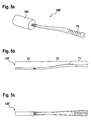
- Fig. 5a shows a further embodiment of an application aid 100 'according to the invention, which has an application rod 120' and a wound cleaning head 150 attached to its fastening section.
- Fig. 5b shows the application rod 120 'in a first side view
- Fig. 5c shows the application rod 120 'in a side view rotated by 90 °.
- the application rod 120 ' essentially corresponds to the above-described application rods 20, 120, so that reference can be made to the above statements.
- the application rod 120 In contrast to the application rod 120 Fig. 4b the application rod 120 'is curved in sections to improve manageability.
- the longitudinal profile of the application rod is approximated to a trowel shape in which a rear section 71 of the application rod essentially runs in a first plane and a front section 72 of the application rod runs essentially in a second plane offset with respect to the first plane , wherein the central section 73 of the application rod extends from the first plane into the second plane.
- the application rod 120 ′ has a corrugation 75 to increase the slip resistance.
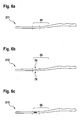
- Application rod 211 shown in its bending section 26 has a substantially constant rod cross-section, has the in Fig. 6b
- the application rod shown has a taper in the form of two notches 78 which are introduced into the bending section 26 from opposite sides of the application rod, the direction in which the notches run perpendicular to a main bending direction of the application rod.
- the in Fig. 6c The application rod shown has a plurality of circumferential notches 79 which increase the flexibility of the application rod in both transverse directions perpendicular to the longitudinal direction of the application rod. These notches 79 are formed in an area of the bending section 26 which has a different material than the areas adjacent to the bending section 26. This material is designed in such a way that it gives the bending section 26 increased flexibility. This material can have an elastomer, for example.
- the wound cleaning head 50 preferably has polyester fibers, preferably polyester fibers made of polypropylene, for the effective removal of debris and exudate from the wound and of dandruff and keratoses from the wound surrounding skin.
- a soft fiber composite can result in a painless application with a high level of comfort.
- the shatterproof handle preferably made of polypropylene, offers easy access to deep wounds and difficult to reach wound locations.
- the wound cleaning head Before cleaning a wound, the wound cleaning head can be wetted with a wound irrigation solution.
- the application aid according to the invention is particularly well suited for the debridement of acute and chronic, superficial to deep wounds - also surgically invasive. Previous problems in use due to too much or too little deflection of the application rod can be avoided.
Landscapes
- Health & Medical Sciences (AREA)
- Life Sciences & Earth Sciences (AREA)
- General Health & Medical Sciences (AREA)
- Heart & Thoracic Surgery (AREA)
- Veterinary Medicine (AREA)
- Animal Behavior & Ethology (AREA)
- Engineering & Computer Science (AREA)
- Biomedical Technology (AREA)
- Public Health (AREA)
- Surgery (AREA)
- Vascular Medicine (AREA)
- Epidemiology (AREA)
- Nuclear Medicine, Radiotherapy & Molecular Imaging (AREA)
- Pathology (AREA)
- Hematology (AREA)
- Oral & Maxillofacial Surgery (AREA)
- Medical Informatics (AREA)
- Molecular Biology (AREA)
- Anesthesiology (AREA)
- Surgical Instruments (AREA)
- Cleaning Implements For Floors, Carpets, Furniture, Walls, And The Like (AREA)
- Media Introduction/Drainage Providing Device (AREA)
- Materials For Medical Uses (AREA)
- Medicinal Preparation (AREA)
- Medicines Containing Material From Animals Or Micro-Organisms (AREA)
- Detergent Compositions (AREA)
Description
- Die Erfindung betrifft eine Applikationshilfe für die Behandlung von Wunden. Die Applikationshilfe soll insbesondere zum Debridement und/oder zur Reinigung von Wunden einsetzbar sein.
- Als Debridement wird allgemein die Entfernung von Verunreinigungen wie etwa abgestorbenem Gewebe, Debris und Exsudat sowie Schuppen und Keratosen aus Wunden und der Wundumgebungshaut bezeichnet. Ziel ist eine Reinigung der Wunde, eine verbesserte Gewährleistung der Wundbeobachtung sowie eine Förderung der Heilung. Das Debridement insbesondere von tiefen - auch chirurgisch invasiven - Wunden wie etwa diabetischen Ulcera, arteriellen und venösen Ulcera, Dekubitalulcera, postoperativen und sekundärheilenden Wunden, Traumata, Verbrennungen und Verbrühungen ist typischerweise zur Beschleunigung des Heilprozesses und zum Verhindern einer sekundären Infektion der Wunde erforderlich.
- Hierzu können Applikationshilfen mit einem Applikationsstab verwendet werden, an dessen vorderem Ende ein Wundbehandlungskopf angebracht ist. Der Applikationsstab kann eine Länge haben, die eine Behandlung und Reinigung auch tiefer Wunden mittels des Wundbehandlungskopfs ermöglicht.
- Herkömmliche Applikationshilfen haben allerdings mitunter zu Verletzungen der Wunde oder der Wundumgebung geführt.
- In Anbetracht dieser Probleme ist es die Aufgabe der vorliegenden Erfindung, eine Applikationshilfe zur Behandlung von akuten und chronischen, oberflächlichen bis tiefen Wunden bereitzustellen, die eine gute Reinigungsleistung ohne die Gefahr von Verletzungen ermöglicht.
- Diese Aufgabe wird erfindungsgemäß durch die im unabhängigen Patentanspruch 1 angegebene Weiterbildung der eingangs beschriebenen Applikationshilfe gelöst.
- Die Erfindung geht auf die Erkenntnis zurück, dass ein starrer Applikationsstab insbesondere beim Einsatz in tiefen Wunden zu Verletzungen führen kann, wenn der Anwender die Wunde unter Anwendung von zu hoher Druckkraft behandelt. Bspw. kann ein steifer bzw. unnachgiebiger Applikationsstab zu Druckstellen oder Rissen in der Wundumgebung führen, wenn er in eine tiefe Wunde eingeführt oder darin bewegt wird.
- Demgegenüber gibt der biegsame Applikationsstab der erfindungsgemäßen Applikationshilfe bei zu hoher Kraftausübung durch den Anwender nach, so dass eine Verletzung der Wunde und der Wundumgebung verhindert werden kann.
- Vorzugsweise verformt sich der Applikationsstab der erfindungsgemäßen Applikationshilfe bei Ausübung einer Biegekraft in einer Querrichtung des Stabs bis hin zu einer Elastizitätsgrenze flexibel bzw. elastisch. Mit anderen Worten verbiegt sich der Applikationsstab bei Einwirkung einer Biegekraft senkrecht zu der Längsrichtung des Applikationsstabs in reversibler Weise und kehrt bei Aufhebung der Krafteinwirkung in seinen Ursprungszustand zurück. Mit der erfindungsgemäßen Applikationshilfe mit dem biegsamen, insbesondere dem elastisch verformbaren Applikationsstab ist ein Debridement von oberflächlichen bis tiefen Wunden ohne die Gefahr einer Verletzung der Wunde möglich.
- Die Handhabbarkeit der erfindungsgemäßen Applikationshilfe kann dadurch verbessert werden, dass ein hinterer Abschnitt des Applikationsstabs als ein Haltegriffabschnitt ausgebildet ist, der bspw. die Form eines Handgriffs haben kann. Bei einigen Ausführungsformen ist der Haltegriffabschnitt im Hinblick auf eine verbesserte Griffigkeit gekrümmt und/oder profiliert. Bspw. weist der Haltegriffabschnitt sich in der Längsrichtung des Applikationsstabs erstreckende Wellungen zum Einlegen von Fingern auf. Ein Verrutschen des Applikationsstabs relativ zu der Hand des Anwenders kann zuverlässig verhindert werden.
- Ein vorderer Abschnitt des Applikationsstabs kann als ein Befestigungsabschnitt zum Befestigen eines Wundreinigungskopfs ausgebildet sein, wobei der Wundreinigungskopf bspw. ein Wundreinigungstuch oder ein Wundreinigungspad sein kann. Nach der Befestigung des Wundreinigungskopfs an dem Befestigungsabschnitt kann der Wundreinigungskopf den Befestigungsabschnitt vorzugsweise vollständig umlaufen bzw. umhüllen. Hierdurch wird sichergestellt, dass ausschließlich der Wundreinigungskopf, nicht jedoch das vordere Ende des Applikationsstabs in Kontakt mit dem Wundgewebe kommt. Als Wundreinigungstuch oder Wundreinigungspad wird vorliegend ein flächiges textiles Gebilde, einschließlich Watte, Vlies, Gewebe etc. bezeichnet, das je nach Bedarf und je nach Einsatzbereich aus natürlichen und/oder synthetischen Fasern besteht und die gewünschten Reinigungseigenschaften aufweist.
- Die Flexibilität des Applikationsstabs wird erfindungsgemäß dadurch verbessert werden, dass zwischen dem Haltegriffabschnitt und dem Befestigungsabschnitt ein Biegeabschnitt mit erhöhter Biegsamkeit angeordnet ist.
- Vorzugsweise weist der Applikationsstab in dem Biegeabschnitt einen gegenüber dem Haltegriffabschnitt verkleinerten Stabquerschnitt und/oder zumindest eine sich quer zur Längsrichtung des Applikationsstabs erstreckende Kerbe oder Vertiefung zum Erhöhen der Biegsamkeit auf.
- Im Hinblick auf eine gute Reinigungsleistung bei Anwendung in tiefen Wunden hat es sich als zweckmäßig herausgestellt, dass sich der Haltegriffabschnitt über mehr als 1/3 und weniger 2/3 der Länge des Applikationsstabs erstreckt, und/oder sich der Befestigungsabschnitt über mehr als 1/5 und weniger als 1/3 der Länge des Applikationsstabs erstreckt. Bei einer Gesamtlänge des Applikationsstabs zwischen 14 cm und 18 cm kann sich der Haltegriffabschnitt bspw. über eine Länge zwischen 6 cm und 10 cm erstrecken und/oder der Befestigungsabschnitt über eine Länge zwischen 4 cm und 6 cm, insbesondere über etwa 5 cm, erstrecken. Der Befestigungsabschnitt ist vorzugsweise vollständig von dem Wundreinigungskopf bedeckt bzw. umhüllt.
- Nicht nur eine zu hohe Steifheit des Applikationsstabs, sondern auch eine zu hohe Flexibilität kann sich bei der Wundbehandlung als nachteilig erweisen. Bspw. führt eine zu hohe Biegsamkeit des Applikationsstabs dazu, dass der Anwender das Gefühl für die Kraft der Anwendung verliert. Der Anwender glaubt zum Beispiel, die zum Erhalt einer erwünschten Reinigungsleistung erforderliche Kraft bereits aufzuwenden, während tatsächlich aufgrund einer hohen Durchbiegung des Applikationstabs der nötige Druck für die Anwendung nicht erreicht wird.
- Eine besonders gute Reinigungsleistung kann mit einem Applikationsstab erzielt werden, der eine Biegedehnung von 5% bei Einwirkung einer Biegekraft senkrecht zu seiner Längsrichtung erfährt, die einen Wert von 60 N oder weniger, vorzugsweise 45 N oder weniger, besonders bevorzugt 39 N oder weniger und/oder 15 N oder mehr, vorzugsweise 21 N oder mehr, besonders bevorzugt 27 N oder mehr aufweist. Bei einer besonders bevorzugten Ausführungsform der Erfindung führt die Einwirkung einer Biegekraft von 33 N (+/-6 N) auf den Applikationsstab zu einer Biegedehnung von 5% (bei einer Temperatur von 20+/-2°C).
- Vorzugsweise wirkt die Biegekraft dabei auf den Biegeabschnitt des Applikationsstabs, während der vordere und der hintere Abschnitt des Applikationsstabs jeweils auf einer Auflagefläche einer 3-Punkt-Biegevorrichtung mit einer Stützweite St zwischen St=40 mm und St=60 mm aufliegen.
- Im Hinblick auf die Definition der "Biegedehnung" wird auf die Norm EN ISO 178 (Juni 2003) verwiesen, deren Inhalt durch Verweis vollständig in die vorliegende Offenbarung aufgenommen wird.
- Erfindungsgemäß ist der Applikationsstab derart eingerichtet, dass er sich in einer 3-Punkt-Biegevorrichtung mit einer Stützweite zwischen St = 40 mm und St = 60 mm (insbesondere St = 48 mm) bei Einwirkung einer Biegekraft zwischen 21 N und 45 N, insbesondere von etwa 33 N, auf den Biegeabschnitt senkrecht zu der Längsrichtung des Applikationsstabs um etwa s = 5 mm bis s = 8 mm (insbesondere um etwa s = 6,4 mm) durchbiegt (bei einer Temperatur von 20+/-2°C).
- Bei einer Stabdicke (Dicke des Stabs in Richtung der Biegekraft) von h = 3 mm im Bereich des Biegeabschnitts ergibt sich aus der Formel (1) der Norm EN ISO 178 bei einer Durchbiegung von s = 6,4 mm eine Biegedehnung von 5% wie folgt:

- Im Hinblick auf eine Erhöhung der Anwendungssicherheit hat es sich als zweckmäßig herausgestellt, dass der Applikationsstab bruchsicher ausgebildet ist. Mit anderen Worten ist der Applikationsstab besonders weit quer zu seiner Längsrichtung vorzugsweise elastisch auslenkbar, bevor er bricht oder knickt.
- Als ausreichend bruchsicher hat sich ein Applikationsstab herausgestellt, der eine Bruchdehnung von 6% oder mehr, vorzugsweise 8% oder mehr, insbesondere etwa 16% und/oder 50% oder weniger aufweist.
- Im Rahmen dieser Beschreibung und der Ansprüche bezeichnet der Ausdruck "Bruchdehnung" die Biegedehnung - definiert gemäß der Norm EN ISO 178 - bei der der Applikationstab zum ersten Mal bricht. Die Einhaltung einer Obergrenze der Bruchdehnung von 50% kann hilfreich sein, um die Ausübung einer übermäßigen Kraft auf die Wunde zu vermeiden.
- Vorzugsweise wirkt die Biegekraft dabei auf den Biegeabschnitt des Applikationsstabs, während der vordere und der hintere Stababschnitt jeweils auf einer Auflagefläche einer 3-Punkt-Biegevorrichtung mit einer Stützweite St zwischen St = 40 mm und St = 60 mm aufliegen.
- Alternativ oder zusätzlich ist der Applikationsstab derart eingerichtet, dass er in einer 3-Punkt-Biegevorrichtung mit einer Stützweite zwischen St = 40 mm und St = 60 mm (insbesondere St = 48 mm) bei Einwirkung einer Biegekraft auf den Biegeabschnitt senkrecht zu der Längsrichtung des Applikationsstabs selbst dann noch nicht bricht oder knickt, wenn sich eine Durchbiegung s des Applikationsstabs senkrecht zu seiner Längsrichtung von s = 20 mm ergibt (bei einer Temperatur von 20+/-2°C).
- Gemäß der vorliegende Erfindung umfasst die Applikationshilfe zusätzlich einem an einem vorderen Abschnitt des Applikationsstabs befestigten Wundreinigungskopf, insbesondere in Form eines Wundreinigungspads oder Wundreinigungstuchs. Unter einem Wundreinigungstuch wird ein für die Reinigung einer Wunde geeignetes Textil (natürlich und/oder synthetisch) verstanden.
- Eine gute Reinigungswirkung ergibt sich dadurch, dass der Wundreinigungskopf ein Faserpad, insbesondere ein Faserpad mit synthetischen Fasern ist, die vorzugsweise eine Faserstärke zwischen 0,5 und 20 dtex aufweisen. Bei bevorzugten Ausführungsformen der Erfindung beträgt die Faserstärke zwischen 3 und 12 dtex, insbesondere zwischen 5 und 8 dtex. Bei einer besonders bevorzugten Ausführungsform der Erfindung liegt eine Mischung von Fasern mit einer Stärke von etwa 3,3 dtex und etwa 6,7 dtex in einem Mischungsverhältnis von etwa 50:50 vor. (1 dtex = g/10.000 m).
- Dabei kann das Faserpad zumindest eine Trägerschicht und an der Trägerschicht angeordnete und von der Trägerschicht abstehende Fäden aus synthetischen Fasern, insbesondere Kunststofffasern aufweisen, die vorzugsweise ein Flor mit einer Florhöhe zwischen 3 und 30 mm bilden. Bei bevorzugten Ausführungsformen der Erfindung liegt die Florhöhe zwischen 3 und 13 mm, sie beträgt besonders bevorzugt 8 bis 12 mm. Das Flor kann aus Fasern unterschiedlicher Faserstärken gebildet sein. Es können zur Bildung des Flors auch Fasern aus unterschiedlichen Materialien eingesetzt werden. In allen Fällen ist es bevorzugt, wenn die Faserstärke sämtlicher Fasern zwischen 0,5 und 20 dtex beträgt.
- Die Reinigungswirkung kann dadurch weiter verbessert werden, dass die Fäden schräg zu ihrer Längserstreckung verlaufende und vorzugsweise abgeschnittene Enden bzw. Endflächen aufweisen.
- Im Hinblick auf den Aufbau und die Merkmale des einsetzbaren Wundreinigungskopfs wird auf die Druckschrift
WO 2010/085831 A1 verwiesen. Der an dem vorderen Ende des Applikationsstabs der erfindungsgemäßen Applikationshilfe befestigbare oder befestigte Wundreinigungskopf kann einige oder alle Merkmale der in dieser Druckschrift beschriebenen Wundreinigungstücher einzeln oder in beliebiger Kombination aufweisen. - Eine Verletzung der Wunde durch den Applikationsstab kann dadurch zuverlässig verhindert werden, dass der Wundreinigungskopf den vorderen Abschnitt des Applikationsstabs vollständig umläuft oder umhüllt. Insbesondere umläuft der Wundreinigungskopf den zur Befestigung des Wundreinigungskopfs ausgebildeten Befestigungsabschnitt des Applikationsstabs teilweise oder vollständig.
- In einigen Ausführungsformen kann der Wundreinigungskopf derart an dem Befestigungsabschnitt des Applikationsstabs angebracht sein, dass er den Befestigungsabschnitt vollständig umhüllt, wobei der Applikationsstab in Richtung auf den hinteren Abschnitt aus einer in dem Wundreinigungskopf gebildeten Durchgriffsöffnung an dessen hinterem Ende austreten kann.
- Alternativ oder zusätzlich umläuft der Wundreinigungskopf den vorderen Abschnitt des Applikationsstabs vollständig, wobei eine erste Lage des als Wundreinigungstuch ausgebildeten Wundreinigungskopfs auf einer ersten Seite des Applikationstabs (bspw. oberhalb) und eine zweite Lage des Wundreinigungskopfs auf der entgegengesetzten Seite des Applikationsstabs (bspw. unterhalb) angeordnet ist, so dass der vordere Abschnitt des Applikationsstabs zwischen den zwei Lagen angeordnet ist. Der Wundreinigungskopf kann bspw. ein einmal oder mehrmals um den vorderen Abschnitt des Applikationsstabs gewickeltes Pad oder Tuch aufweisen.
- Ein Ablösen des Wundreinigungskopfs von dem Applikationsstab bei der Wundbehandlung kann durch eine hohe Verbindungsfestigkeit zwischen dem Applikationsstab und dem Wundbehandlungskopf verhindert werden. Vorzugsweise ist die Verbindungsfestigkeit zwischen dem Wundbehandlungskopf und dem Applikationsstab bei einem Abziehen des Wundreinigungskopfs von dem Applikationsstab in Längsrichtung des Applikationsstabs größer als 25 N, besonders bevorzugt größer als 50 N. Insbesondere ist die Verbindungsfestigkeit 70 N oder größer. Unter einer Verbindungsfestigkeit von 70 N oder mehr wird erfindungsgemäß verstanden, dass sich der Wundreinigungskopf nicht von dem Applikationsstab ablöst, wenn daran mit einer Abziehkraft von 70 N oder mehr in Längsrichtung des Applikationsstabs gezogen wird.
- Bei einer besonders bevorzugten Ausführungsform der Erfindung weist der Wundreinigungskopf eine von dem Applikationsstab durchlaufene Durchgriffsöffnung auf, durch die der Applikationsstab in Richtung auf den hinteren Abschnitt aus dem Wundreinigungskopf austreten kann. Der von dem Wundreinigungskopf umlaufene vordere Abschnitt des Applikationsstabs kann von dem Applikationsstab abstehende Vorsprünge wie etwa Widerhaken aufweisen, die ein Hindurchgleiten des Applikationsstabs durch die Durchgriffsöffnung verhindern. Auf diese Weise kann die Verbindungsfestigkeit zwischen dem Applikationsstab und dem Wundreinigungskopf weiter verbessert werden.
- Alternativ oder zusätzlich kann der Wundreinigungskopf mittels einer oder mehrerer Befestigungsnahten an dem Applikationsstab befestigt sein. Beispielsweise weist der vordere Rand des Wundreinigungskopfs und/oder der dem vorderen Rand entgegengesetzte hintere Rand des Wundreinigungskopfs, der dem Haltegriffabschnitt des Applikationsstabs zugewandt ist, zumindest eine Befestigungsnaht auf.
- Die Verbindungsfestigkeit kann weiter verbessert werden, indem der dem Haltegriffabschnitt zugewandte hintere Rand des Wundreinigungskopfs beidseitig des Applikationsstabs eine Befestigungsnaht aufweist. Beispielsweise kann der dem Haltegriffabschnitt zugewandte hintere Rand des Wundreinigungskopfs eine Stufe oder einen Vorsprung des Applikationsstabs übergreifend vernäht sein. Auf diese Weise kann ein Abziehen des Wundreinigungskopfs von dem Applikationsstab zuverlässig verhindert werden. Insbesondere kann verhindert werden, dass der Applikationsstab bei der Wundbehandlung versehentlich durch eine Durchgriffsöffnung des Wundreinigungskopfs gleiten kann.
- Die Sicherheit bei der Anwendung im chirurgisch-invasiven Bereich kann dadurch verbessert werden, dass zumindest eine der Befestigungsnahten einen Röntgenkontrastfaden (RK-Faden), insbesondere einen mit Bariumsulfat beladenen Kunststoffaden aufweist. Ein RK Faden kann bspw. mit Bariumsulfat beladenes Polypropylen aufweisen.
- Alternativ oder zusätzlich kann die erfindungsgemäße Applikationshilfe darin eingearbeitete oder daran angeordnete RK-Chips, RK-Blättchen und/oder andere Röntgenkontrastmittel aufweisen.
- Im Hinblick auf eine weitere Erhöhung der Verbindungsfestigkeit zwischen dem Applikationsstab und dem Wundbehandlungskopf hat es sich als zweckmäßig erwiesen, dass der Applikationsstab eine Öffnung oder eine Aussparung aufweist, durch die der Wundbehandlungskopf zusätzlich am Applikationsstab gesichert werden kann. Bspw. ist eine auf einer ersten Seite des Applikationsstabs angeordnete Lage des Wundreinigungskopfs durch die Öffnung hindurch mit einer auf einer zweiten Seite des Applikationsstabs angeordneten Lage des Wundreinigungskopfs verbunden, bspw. vernäht.
- Der Applikationsstab kann diese Öffnung in seinem vorderen Abschnitt aufweisen, wobei die Öffnung bspw. als ein sich in Längsrichtung des Applikationsstabs erstreckender Schlitz ausgebildet sein kann. Eine Schlitzöffnung eignet sich besonders gut zum Durchnähen einer Sicherungsnaht durch den Applikationsstab. Die Schlitzöffnung kann eine Länge von 1 cm oder mehr oder 2 cm oder mehr und/oder 5 cm oder weniger aufweisen.
- Alternativ oder zusätzlich kann der Wundreinigungskopf mittels Ultraschallschweißen an dem Applikationsstab befestigt sein.
- Alternativ oder zusätzlich kann der Wundreinigungskopf über einen oder mehrere Widerhaken an dem Applikationsstab befestigt sein. Bspw. weist der Applikationsstab in seinem Befestigungsabschnitt einen oder mehrere von dem Applikationsstab abstehende Widerhaken auf, die den Wundreinigungskopf am Applikationsstab sichern.
- Alternativ oder zusätzlich ist der Wundreinigungskopf mittels eines Haftmittels an dem Applikationsstab befestigt. Bspw. kann der Wundreinigungskopf an den Applikationsstab angeklebt sein. Durch ein Haftmittel kann eine besonders hohe Verbindungsfestigkeit bereitgestellt werden.
- Alternativ oder zusätzlich kann der Wundreinigungskopf mittels eines vorzugsweise lösbaren Klicksystems an dem Applikationsstab befestigt sein. Hierdurch kann eine Wiederverwendung des Stabs und/oder Pads ermöglicht werden.
- Alternativ oder zusätzlich kann der Wundreinigungskopf mittels eines Klettverschlusses an dem Applikationsstab befestigt sein. Hierdurch kann eine Wiederverwendung des Stabs und/oder Pads ermöglicht werden.
- Alternativ oder zusätzlich kann der Wundreinigungskopf mittels eines Formverschlusses an dem Applikationsstab befestigt sein.
- Der Wundreinigungskopf kann an den vorgesehenen Einsatzbereich angepasste Abmessungen haben. Ein kleiner Wundreinigungskopf kann bspw. leichter für Wundtaschen verwendet werden.
- Bei einer bevorzugten Ausführungsform der Erfindung beträgt die Länge des Wundreinigungskopfs in Längsrichtung des Applikationsstabs 3 cm oder mehr und 10 cm oder weniger, insbesondere etwa 5 cm.
- Dabei kann die Breite des Wundreinigungskopfs in einer senkrecht zur Längsrichtung des Applikationsstabs verlaufenden Breitenrichtung 1 cm oder mehr und 5 cm oder weniger, insbesondere etwa 2 cm betragen.
- Das Erkennen der Wundtiefe durch den Anwender kann dadurch ermöglicht werden, dass der Applikationsstab eine Längenskala aufweist. Die Längenskala kann die Entfernung einer oder mehrerer Positionen am Applikationsstab von dem vorderen Ende des Applikationsstabs angeben.
- Alternativ oder zusätzlich können andere Beschriftungen, Logos, Stichcodes; QR-Codes, RFID-Chips o.dgl. an dem Applikationsstab angeordnet sein, um dem Anwender weitere Informationen zur Verfügung zu stellen.
- Bei einer besonders bevorzugten Ausführungsform der Erfindung ist ein Haltegriffabschnitt des Applikationsstabs rutschfest ausgebildet, so dass er auch mit Handschuhen ergriffen werden kann, ohne dass die Gefahr des Abrutschens besteht.
- Im Hinblick auf eine verbesserte Griffigkeit des Haltegriffabschnitts hat es sich als zweckmäßig erwiesen, dass der Haltegriffabschnitt eine Profilierung aufweist, insbesondere eine Wellung, ein sich in Längsrichtung des Applikationsstabs in Richtung auf dessen hinteres Ende zumindest abschnittsweise erweiterndes Querschnittprofil und/oder eine ergonomische Form zum Erhöhen der Rutschfestigkeit.
- Die Handhabbarkeit der erfindungsgemäßen Applikationshilfe kann dadurch weiter verbessert werden, dass der Applikationsstab zumindest abschnittsweise gebogen oder gekrümmt ist. Bspw. erstrecken sich ein hinterer Abschnitt des Applikationsstabs im Wesentlichen in einer ersten Ebene und ein vorderer Abschnitt des Applikationsstabs im Wesentlichen in einer bzgl. der ersten Ebene versetzten zweiten Ebene, wobei der mittlere Abschnitt des Applikationsstabs von der ersten Ebene in die zweite Ebene gekrümmt verläuft. Hierdurch kann sich ein Verlauf des Applikationsstabs nach Art einer Kelle ergeben, der bspw. im Hinblick auf die Anwendung bei tiefen Wunden bevorzugt sein kann.
- Die Herstellung des Applikationsstabs kann dadurch vereinfacht werden, dass dieser zumindest teilweise und vorzugsweise vollständig aus Kunststoff, bspw. auf Polypropylen, gebildet ist. Bspw. kann der Applikationsstab einstückig aus Kunststoff geformt werden.
- Im Hinblick auf die Behandlung tiefer Wunden hat sich eine Gesamtlänge des Applikationsstabs von 10 cm oder mehr und 20 cm oder weniger, insbesondere von etwa 15-16 cm als geeignet erwiesen.
- Bei einer erfindungsgemäßen Applikationshilfe kann ein Bereich des Biegeabschnitts einen Werkstoff geringerer Biegefestigkeit aufweisen als die an den Biegeabschnitt angrenzenden Abschnitte.
- Die Applikationshilfe kann im Hinblick auf die Anwendung in Wunden steril bzw. entkeimt sein.
- In der folgenden Beschreibung wird die Erfindung unter Bezugnahme auf die beigefügten Zeichnungen erläutert. In der Zeichnung zeigt
- Fig. 1
- eine schematische Seitenansicht einer Applikationshilfe mit Wundbehandlungskopf gemäß der vorliegenden Erfindung;
- Fig. 2
- eine erste schematische Seitenansicht eines Applikationsstabs einer erfindungsgemäßen Applikationshilfe;
- Fig. 3
- eine um 90° gedrehte zweite schematische Seitenansicht des in
Fig. 2 gezeigten Applikationsstabs; - Fig. 4a-4c
- verschiedene Ansichten einer Applikationshilfe gemäß der vorliegenden Erfindung;
- Fig. 5a-5c
- verschiedene Ansichten einer Applikationshilfe gemäß der vorliegenden Erfindung;
- Fig. 6a-6c
- Seitenansichten verschiedener Applikationsstäbe von Applikationshilfen gemäß der vorliegenden Erfindung; und
- Fig. 7
- ein Verfahren zum Messen der Biegsamkeit von Applikationsstäben.
- In
Fig. 1 ist eine erfindungsgemäße Applikationshilfe 10 in einer schematischen Seitenansicht dargestellt. Die Applikationshilfe 10 besteht aus einem biegbaren Applikationsstab 20 und einem als Wundreinigungspad ausgebildeten Wundreinigungskopf 50, der an einem vorderen Abschnitt des Applikationsstabs 20 befestigt ist.Fig. 2 zeigt den Applikationsstab 20 ohne daran befestigten Wundreinigungskopf 50. - Ein hinterer Abschnitt des Applikationsstabs 20 ist als ein Haltegriffabschnitt 22 ausgebildet, ein mittlerer Abschnitt des Applikationsstabs 20 ist als eine Biegeabschnitt 26 mit erhöhter Biegsamkeit ausgebildet, und der vordere Abschnitt des Applikationsstabs ist als ein Befestigungsabschnitt 24 zum Befestigen des Wundreinigungskopfs 50 ausgebildet.
- Bei der in
Fig. 1 dargestellten Ausführungsform umläuft der nur schematisch angedeutete Wundreinigungskopf 50 den Befestigungsabschnitt 24 vollständig, so dass bei der Behandlung von Wunden mit der Applikationshilfe 10 ein direkter Kontakt zwischen der Wunde und dem vorderen Ende des Applikationsstabs 20 vermieden wird. - Der Applikationsstab 20 erstreckt sich in einer Längsrichtung und hat vorzugsweise eine Gesamtlänge L zwischen 10 cm und 20 cm, insbesondere etwa 15-16 cm. Der Haltegriffabschnitt 22 kann sich etwa über die Hälfte der Gesamtlänge des Applikationsstabs erstrecken, während der Befestigungsabschnitt an die Länge X des Wundreinigungskopfs angepasst sein kann und bspw. eine Länge von etwa 5 cm aufweisen kann. Bei einer bevorzugten Ausführungsform hat der Wundreinigungskopf eine Länge X von etwa 5 cm und eine Breite B von etwa 2-3 cm.
- Der Applikationsstab 20 kann in dem Haltegriffabschnitt 22 eine Profilierung 32 wie etwa eine Wellung zum Verbessern seiner Griffigkeit aufweisen, und er kann ferner einen sich in Richtung auf den Wundreinigungskopf 50 verkleinernden Querschnitt aufweisen, wie bspw. in
Fig. 3 angedeutet ist. -
Fig. 3 zeigt einen Applikationsstab 20 einer erfindungsgemäßen Applikationshilfe 10 in einer um 90° gedrehten Seitenansicht. Die maximale Dicke D des Applikationsstabs in dem Haltegriffabschnitt 22 kann etwa 5-7 mm betragen, während der Biegeabschnitt 26 eine Dicke von nur etwa 2-4 mm, insbesondere etwa 3 mm haben kann. - In den
Figuren 1 und2 ist ferner eine in dem Biegeabschnitt 26 und in einem vorderen Bereich des Haltegriffabschnitts 22 angeordnete Skala 31 zum Ablesen einer Wundtiefe dargestellt. - Der Applikationsstab 20 ist elastisch verformbar und kehrt bei Auslenkung in einer Querrichtung Q wieder in seinen unbelasteten Zustand zurück.
- Die Biegesteifigkeit des Applikationsstabs 20 ist dabei derart eingerichtet, dass sich der Applikationsstab bei einer übermäßigen Druckausübung durch den Anwender durchbiegt, wodurch Verletzungen der zu behandelnden Wunde verhindert werden können. Gleichzeitig ist die Biegesteifigkeit ausreichend hoch, so dass der Anwender nicht das Gefühl für die Kraft seiner Anwendung verliert.
- Die Biegsamkeit der Applikationsstabs ist insbesondere derart eingerichtet, dass sich bei Einwirkung einer Biegekraft auf den Applikationsstab senkrecht zu dessen Längsrichtung mit einem zwischen 21 N und 45 N liegenden Wert, insbesondere von etwa 33 N, eine Biegedehnung des Applikationsstabs von etwa 5% ergibt.
- Unter Bezugnahme auf
Fig. 7 wird im Folgenden ein Verfahren zum Bestimmen der Biegedehnung eines Applikationsstabs mittels einer 3-Punkt-Biegevorrichtung erläutert, wobei die Messung in Anlehnung an das in der Norm DIN EN ISO 178 beschriebene Verfahren durchgeführt wird. -
Fig. 7 zeigt im oberen Teil ein Prüfgerät 300 mit einem Auflager 310 und einer darüber angeordneten Druckfinne 320. Das Auflager 310 weist eine erste Auflagefläche 311 zur Auflage des Haltegriffabschnitts 22 eines Applikationsstabs und eine davon beabstandete zweite Auflagefläche 312 zur Auflage des vorderen Abschnitts 24 des Applikationsstabs 20 auf. Der Biegeabschnitt 26 des Applikationstabs ist oberhalb eines Zwischenraums zwischen den beiden Auflageflächen 311, 312 angeordnet, wobei der Zwischenraum eine Stützweite St von St=40 mm oder mehr und St=60 mm oder weniger, insbesondere etwa St=48 mm hat. Eine vertikale Anschlagfläche 330 vereinfacht die korrekte Positionierung des Applikationsstabs auf dem Auflager 310. - Die Druckfinne 320 weist an ihrem unteren Ende eine Druckfläche auf und ist senkrecht zu der Längsrichtung des Applikationsstabs beweglich eingerichtet. Wie in dem unteren Teil von
Fig. 7 dargestellt ist, wird die Druckfinne 320 unter Ausübung einer Biegekraft auf den Applikationsstab 20 von oben in den Zwischenraum zwischen den beiden Auflageflächen hineinbewegt, bis hin zu einer inFig. 7 gezeigten voreinstellbaren Endstellung, in der sich eine vorgegebene Durchbiegung s des Applikationsstabs senkrecht zu dessen Längsrichtung ergibt. Die von der Druckfinne 320 in der Endstellung auf den Applikationsstab ausgeübte Biegekraft ist messbar. - Bei einer Stabdicke von h = 3 mm im Biegeabschnitt, auf den die Biegekraft einwirkt, ergibt sich aus der Formel (εf = 600 ∗ s ∗ h / St2 %) bei einer Durchbiegung von etwa s=6,4 mm eine Biegedehnung von 5%.
- Für eine solche Biegedehnung sollte vorzugsweise eine Biegekraft zwischen 21 N und 45 N erforderlich sein, insbesondere eine Biegekraft von etwa 33 N. Ein Applikationsstab erfüllt also insbesondere dann die bevorzugten Biegeeigenschaften, wenn sich bei einer von der Druckfinne ausgeübten Biegekraft von etwa 33 N eine Durchbiegung s zwischen 5 mm und 8 mm, insbesondere etwa 6,4 mm ergibt.
- Ferner ist der erfindungsgemäße Applikationsstab vorzugsweise besonders bruchfest gegenüber einer Biegebelastung eingerichtet. Insbesondere sollte der Applikationsstab bei einer Biegedehnung von 8%, insbesondere selbst bei einer Biegedehnung von 16% noch nicht brechen oder knicken.
- Mittels der in
Fig. 7 dargestellten Messvorrichtung kann gemessen werden, ob ein Applikationsstab eine solche Bruchfestigkeit aufweist. - Die Bruchfestigkeit kann an einem Applikationsstab mit daran befestigtem Wundreinigungskopf gemessen werden.
- Der Applikationsstab 20 wird wie oben beschrieben auf das Auflager 310 des Prüfgeräts 300 aufgelegt, und die Druckfinne 320 wird zum Ausüben einer Biegekraft auf den Biegeabschnitt 26 des Applikationsstabs in den Zwischenraum zwischen den beiden Auflageflächen 311, 312 mit einer Stützweite St zwischen 40 mm und 60 mm, insbesondere etwa 48 mm, hineinbewegt.
- Wenn der Applikationsstab 20 bei einer Durchbiegung von s=20 mm noch nicht bricht oder knickt, widersteht er einer Biegedehnung von 16% oder mehr und erfüllt die erfindungsgemäß bevorzugten Eigenschaften im Hinblick auf seine Bruchfestigkeit.
- Der Wundreinigungskopf 50 ist bei der erfindungsgemäßen Applikationshilfe 10 mit einer hohen Verbindungsfestigkeit von 70 N oder mehr an dem Applikationsstab 20 befestigt. Mit anderen Worten löst sich der Wundreinigungskopf selbst dann noch nicht von dem Applikationsstab 20, wenn der Wundreinigungskopf 50 mit einer Zugkraft von 70 N, 75 N oder mehr in Längsrichtung des Applikationsstabs 20 nach oben (siehe
Fig. 1 ) gezogen wird. Bei einer praktischen Anwendung der Applikationshilfe 10 zur Reinigung einer Wunde wird dadurch ausgeschlossen, dass sich der Wundreinigungskopf 50 beim Herausziehen aus der Wunde von dem Applikationsstab 20 löst. Zur sicheren Verbindung des Wundreinigungskopfs 50 an dem Applikationsstab 20 hat sich dabei eine Verbindungsfestigkeit von 70 N als besonders hilfreich erwiesen. In der Praxis kann aber auch eine Verbindungsfestigkeit in einem Bereich von 50 N oder mehr ausreichend sein. - Die Verbindungsfestigkeit zwischen dem Applikationsstab 20 und dem Wundreinigungskopf 50 kann mittels eines Zugprüfgeräts gemessen werden, das eine Halterung zum Fixieren des Applikationsstabs und eine Abzugsvorrichtung zum Ziehen an dem Wundreinigungskopf aufweist, wobei die Halterung und die Abzugsvorrichtung mit einer vorgegebenen Zugkraft auseinander gezogen werden können. Die zum Ablösen des Wundreinigungskopfs von dem Applikationsstab erforderliche Zugkraft kann auf diese Weise bestimmt werden.
- Der Wundreinigungskopf 50 kann mittels einer oder mehrerer Befestigungsnahten an dem Applikationsstab 20 befestigt sein. Bspw. ist der Wundreinigungskopf am unteren Ende beidseitig und am oberen Ende vernäht.
- Zusätzlich kann der Wundreinigungskopf 50 durch eine Öffnung 29 des Applikationsstabs 20 hindurch vernäht sein. Bspw. ist eine oberhalb der Öffnung 29 angeordnete Lage des Wundreinigungskopfs 50 mit einer unterhalb der Öffnung angeordneten Lage des Wundreinigungskopfs 50 vernäht, um die Verbindung zwischen dem Applikationsstab 20 und dem Wundreinigungskopf abzusichern.
- Zumindest ein Nähfaden kann dabei eine Röntgenkontrastfähigkeit aufweisen und bspw. als mit Bariumsulfat beladener Kunststoffaden ausgebildet sein. Dieser RK-Faden (nicht dargestellt) umläuft bspw. den Applikationsstab 20 an dem unteren Ende des Wundreinigungskopfs in
Fig. 1 . - Der Wundreinigungskopf 50 kann ferner eine von dem Applikationsstab 20 durchlaufene Öffnung 51 an seinem in
Fig. 1 unteren Ende ausbilden, wobei ein Herausziehen des Applikationsstabs 20 durch die Öffnung 51 durch Vorsprünge 27 oder Widerhaken verhindert wird, die von dem Applikationsstab 20 in einer Breitenrichtung nach außen vorstehen. - Zusätzlich kann der Wundreinigungskopf mittels Ultraschallverschweißen an dem Applikationsstab 20 angebracht sein.
-
Fig. 4a zeigt eine weitere Ausführungsform einer erfindungsgemäßen Applikationshilfe 100, die einen Applikationsstab 120 und einen an dessen Befestigungsabschnitt angebrachten Wundreinigungskopf 150 aufweist.Fig. 4b zeigt den Applikationsstab 120 in einer ersten Seitenansicht, undFig. 4c zeigt den Applikationsstab 120 in einer um 90° gedrehten Seitenansicht. - Es ist in den
Figuren 4b und 4c deutlich erkennbar, dass der hintere Abschnitt des Applikationsstabs als Haltegriffabschnitt mit einer Profilierung 32 in Form von Wellungen ausgebildet ist. Im Hinblick auf eine besonders ergonomische Form mit guter Rutschfestigkeit verjüngt sich der Querschnitt des Haltegriffabschnitts in Richtung des Biegeabschnitts 26. - Zum Erhöhen der Biegsamkeit des Applikationsstabs 120 weist dieser in dem Biegeabschnitt 26 Einkerbungen bzw. Vertiefungen auf. Diese Einkerbungen sind in einem Bereich des Biegeabschnitts 26 angeordnet, der einen anderen Werkstoff aufweist, als die an den Biegeabschnitt 26 angrenzenden Bereiche. Dieser Werkstoff ist derart gewählt, dass er dem Biegeabschnitt 26 eine erhöhte Biegsamkeit verleiht. Dieser Werkstoff kann beispielsweise ein Elastomer aufweisen.
- Der Applikationsstab 120 erstreckt sich im Wesentlichen linear und weist keine Biegung auf.
-
Fig. 5a zeigt eine weitere Ausführungsform einer erfindungsgemäßen Applikationshilfe 100', die einen Applikationsstab 120' und einen an dessen Befestigungsabschnitt angebrachten Wundreinigungskopf 150 aufweist.Fig. 5b zeigt den Applikationsstab 120' in einer ersten Seitenansicht, undFig. 5c zeigt den Applikationsstab 120' in einer um 90° gedrehten Seitenansicht. Der Applikationsstab 120' entspricht im Wesentlichen den oben beschriebenen Applikationsstäben 20, 120, so dass auf die obigen Ausführungen verwiesen werden kann. - Im Unterschied zu dem Applikationsstab 120 aus
Fig. 4b ist der Applikationsstab 120' zur Verbesserung der Handhabbarkeit abschnittsweise gekrümmt. In der inFig. 5b gezeigten Seitenansicht ist erkennbar, dass der Längsverlauf des Applikationstabs an eine Kellenform angenähert ist, bei der ein hinterer Abschnitt 71 des Applikationsstabs im Wesentlichen in einer ersten Ebene und ein vorderer Abschnitt 72 des Applikationsstabs im Wesentlichen in einer bzgl. der ersten Ebene versetzten zweiten Ebene verläuft, wobei der mittlere Abschnitt 73 des Applikationsstabs von der ersten Ebene in die zweite Ebene gekrümmt verläuft. - Anstelle der als Wellung ausgebildeten Profilierung 32 weist der Applikationsstab 120' eine Riffelung 75 zum Erhöhen der Rutschfestigkeit auf.
- In den
Figuren 6a bis 6c sind verschiedene Applikationsstäbe 211, 212, 213 erfindungsgemäßer Applikationshilfen jeweils in einer Seitenansicht dargestellt. - Während der in
Fig. 6a dargestellte Applikationsstab 211 in seinem Biegeabschnitt 26 einen im Wesentlichen konstanten Stabquerschnitt hat, weist der inFig. 6b dargestellte Applikationsstab eine Verjüngung in Form von zwei von entgegengesetzten Seiten des Applikationsstabs in den Biegeabschnitt 26 eingebrachten Kerben 78 auf, wobei die Verlaufsrichtung der Kerben senkrecht zu einer Hauptbiegerichtung des Applikationsstabs verläuft. Der inFig. 6c dargestellte Applikationsstab weist mehrere umlaufende Einkerbungen 79 auf, die die Biegsamkeit des Applikationsstabs in beiden senkrecht zu der Längsrichtung des Applikationsstabs verlaufenden Querrichtungen erhöhen. Diese Einkerbungen 79 sind in einem Bereich des Biegeabschnitts 26 ausgebildet, der einen anderen Werkstoff aufweist als die an den Biegeabschnitt 26 angrenzenden Bereiche. Dieser Werkstoff ist derart beschaffen, dass er dem Biegeabschnitt 26 eine erhöhte Biegsamkeit verleiht. Dieser Werkstoff kann beisppielsweise ein Elastomer aufweisen. - Im Hinblick auf den Aufbau und die Merkmale des Wundreinigungskopfs 50 wird auf die Druckschrift
WO 2010/085831 A1 verwiesen. Vorzugsweise weist der Wundreinigungskopf Polyesterfasern, vorzugsweise Polyesterfasern aus Polypropylen, zum effektiven Entfernen von Debris und Exsudat aus der Wunde sowie von Schuppen und Keratosen aus der Wundumgebungshaut auf. Ein weicher Faserverbund kann für eine schmerzarme Anwendung bei hohem Anwendungskomfort führen. - Der bruchsichere Griff, vorzugsweise aus Polypropylen, bietet einfachen Zugang zu tiefen Wunden und schwer zu erreichenden Wundlokalisationen.
- Höchste Anwendungssicherheit kann durch präzise Befestigungsnähte, einen ergonomischen Griff und nachverfolgbare Röntgenkontrastfäden gewährleistet werden.
- Vor der Reinigung einer Wunde kann der Wundreinigungskopf mit einer Wundspüllösung benässt werden.
- Die erfindungsgemäße Applikationshilfe ist besonders gut für das Debridement von akuten und chronischen, oberflächlichen bis tiefen Wunden - auch chirurgisch invasiv - geeignet. Frühere Probleme in der Anwendung aufgrund einer zu hohen oder einer zu geringen Durchbiegung des Applikationsstabs können vermieden werden.
Claims (30)
- Applikationshilfe (10, 100, 100') für die Behandlung von Wunden, insbesondere für das Debridement und/oder die Reinigung von Wunden, mit einem biegbaren Applikationsstab (20, 120, 120', 211, 212, 213), bei dem ein hinterer Abschnitt des Applikationsstabs (20) als ein Haltegriffabschnitt (22) und/oder ein vorderer Abschnitt des Applikationsstab als ein Befestigungsabschnitt (24) zum Befestigen eines Wundreinigungskopfs (50, 150) ausgebildet ist, gekennzeichnet durch einen zwischen dem Haltegriffabschnitt (22) und dem Befestigungsabschnitt (24) bereitgestellten Biegeabschnitt (26) mit erhöhter Biegsamkeit, wobei sich der Applikationsstab (20) in einer 3-Punkt-Biegevorrichtung mit einer Stützweite zwischen 40 mm und 60 mm bei Einwirkung einer Biegekraft zwischen 21 N und 45 N, insbesondere von etwa 33 N, auf den Biegeabschnitt senkrecht zu der Längsrichtung des Applikationsstabs um etwa 5 bis 8 mm durchbiegt.
- Applikationshilfe nach Anspruch 1, dadurch gekennzeichnet, dass der Applikationsstab (20) in dem Biegeabschnitt (26) einen gegenüber dem Haltegriffabschnitt (22) verkleinerten Stabquerschnitt und/oder eine sich quer zur Längsrichtung des Applikationsstabs erstreckende Kerbe oder Vertiefung zum Erhöhen der Biegsamkeit aufweist.
- Applikationshilfe nach einem der Ansprüche 1 oder 2, dadurch gekennzeichnet, dass sich der Haltegriffabschnitt (22) über mehr als 1/3 und weniger als 2/3 der Länge (L) des Applikationsstabs (20) erstreckt und/oder sich der Befestigungsabschnitt (24) über mehr als 1/5 und weniger als 1/3 der Länge des Applikationsstabs (20) erstreckt, wobei die Länge des Befestigungsabschnitts (24) bevorzugt etwa 5 cm beträgt.
- Applikationshilfe nach einem der vorhergehenden Ansprüche, dadurch gekennzeichnet, dass sich eine Biegedehnung des Applikationsstabs (20) von 5% bei Einwirkung einer Biegekraft auf den Applikationsstab senkrecht zu dessen Längsrichtung von 60 N oder weniger, vorzugsweise 45 N oder weniger, besonders bevorzugt 39 N oder weniger und/oder 15 N oder mehr, vorzugsweise 21 N oder mehr, besonders bevorzugt 27 N oder mehr, insbesondere von etwa 33 N ergibt.
- Applikationshilfe nach einem der vorhergehenden Ansprüche, dadurch gekennzeichnet, dass der Applikationsstab (20) bruchfest ausgebildet ist, insbesondere dass die Bruchdehnung des Applikationsstabs 6% oder mehr, vorzugsweise 8% oder mehr und/oder 50% oder weniger, insbesondere etwa 16% beträgt.
- Applikationshilfe nach einem der vorhergehenden Ansprüche, gekennzeichnet durch einen an einem vorderen Abschnitt des Applikationsstabs befestigten Wundreinigungskopf (50), insbesondere in Form eines Wundreinigungspads oder Wundreinigungstuchs.
- Applikationshilfe nach Anspruch 6, dadurch gekennzeichnet, dass der Wundreinigungskopf (50) ein Faserpad, insbesondere ein Faserpad mit synthetischen Fasern aufweist, die vorzugsweise eine Faserstärke zwischen 0,5 und 20 dtex aufweisen.
- Applikationshilfe nach Anspruch 7, dadurch gekennzeichnet, dass das Faserpad zumindest eine Trägerschicht und an der Trägerschicht angeordnete und von der Trägerschicht abstehende Fäden aus synthetischen Fasern, insbesondere Kunststofffasern aufweist, die vorzugsweise ein Flor mit einer Florhöhe zwischen 3 und 30 mm bilden.
- Applikationshilfe nach Anspruch 8, dadurch gekennzeichnet, dass die Fäden schräg zu ihrer Längserstreckung verlaufende und vorzugsweise abgeschnittene Enden bzw. Endflächen aufweisen.
- Applikationshilfe nach einem der Ansprüche 6 bis 9, dadurch gekennzeichnet, dass der Wundreinigungskopf (50) den Befestigungsabschnitt (24) des Applikationsstabs (20) vorzugsweise vollständig umläuft oder umhüllt.
- Applikationshilfe nach einem der Ansprüche 6 bis 10, gekennzeichnet durch eine Verbindungsfestigkeit zwischen dem Wundreinigungskopf (50) und dem Applikationsstab (20) bei einem Abziehen des Wundreinigungskopfs von dem Applikationsstab in Längsrichtung des Applikationsstabs von 25 N oder mehr, vorzugsweise 50 N oder mehr, insbesondere 70 N oder mehr.
- Applikationshilfe nach einem der Ansprüche 6 bis 11, dadurch gekennzeichnet, der Wundreinigungskopf eine von dem Applikationsstab (20) durchlaufene Durchgriffsöffnung (51) aufweist, wobei der Befestigungsabschnitt (24) des Applikationsstabs von dem Applikationsstab abstehende Vorsprünge (27) wie etwa Widerhaken aufweist, die ein Hindurchgleiten des Applikationsstabs durch die Durchgriffsöffnung (51) verhindern.
- Applikationshilfe nach einem der Ansprüche 6 bis 12, dadurch gekennzeichnet, dass der Wundreinigungskopf (50) mittels einer oder mehrerer Befestigungsnahten an dem Applikationsstab (20) befestigt ist.
- Applikationshilfe nach Anspruch 13, dadurch gekennzeichnet, dass ein dem Haltegriffabschnitt (22) des Applikationsstabs (20) zugewandter Rand (52) des Wundreinigungskopfs (50) einseitig oder beidseitig des Applikationsstabs eine Befestigungsnaht aufweist, und/oder dass ein vorderer Rand (54) des Wundreinigungskopfs zumindest eine Befestigungsnaht aufweist.
- Applikationshilfe nach einem der Ansprüche 13 bis 14, dadurch gekennzeichnet, dass zumindest eine der Befestigungsnahten einen Röntgenkontrastfaden, insbesondere einen RK-Faden aufweist.
- Applikationshilfe nach einem der Ansprüche 12 bis 15, dadurch gekennzeichnet, dass der Applikationsstab eine Öffnung (29) aufweist, durch die eine auf einer ersten Seite des Applikationsstabs angeordnete Lage des Wundreinigungskopfs (50) mit einer auf einer zweiten Seite des Applikationsstabs angeordneten Lage des Wundreinigungskopfs vernäht ist.
- Applikationshilfe nach einem der Ansprüche 6 bis 16, dadurch gekennzeichnet, dass der Wundreinigungskopf mittels eines Haftmittels an dem Applikationsstab befestigt ist, insbesondere an den Applikationsstab geklebt ist.
- Applikationshilfe nach einem der Ansprüche 6 bis 17, dadurch gekennzeichnet, dass der Wundreinigungskopf mittels Ultraschallschweißen an dem Applikationsstab befestigt ist.
- Applikationshilfe nach einem der Ansprüche 6 bis 18, dadurch gekennzeichnet, dass der Wundreinigungskopf mittels eines vorzugsweise lösbaren Klicksystems an dem Applikationsstab befestigt ist.
- Applikationshilfe nach einem der Ansprüche 6 bis 19, dadurch gekennzeichnet, dass der Wundreinigungskopf mittels eines Klettverschlusses an dem Applikationsstab befestigt ist.
- Applikationshilfe nach einem der Ansprüche 6 bis 20, dadurch gekennzeichnet, dass der Wundreinigungskopf mittels eines Formverschlusses an dem Applikationsstab befestigt ist.
- Applikationshilfe nach einem der Ansprüche 6 bis 21, dadurch gekennzeichnet, dass der Wundreinigungskopf mittels eines oder mehrerer Widerhaken an dem Applikationsstab befestigt ist.
- Applikationshilfe nach einem der Ansprüche 6 bis 22, dadurch gekennzeichnet, dass die Länge (X) des Wundreinigungskopfs (50) in der Längsrichtung des Applikationsstabs 3 cm oder mehr und 10 cm oder weniger, insbesondere etwa 5 cm beträgt.
- Applikationshilfe nach einem der Ansprüche 6 bis 23, dadurch gekennzeichnet, dass die Breite (B) des Wundreinigungskopfs (50) senkrecht zu der Längsrichtung des Applikationsstabs (20) 1 cm oder mehr und 5 cm oder weniger, insbesondere etwa 2 cm beträgt.
- Applikationshilfe nach einem der vorhergehenden Ansprüche, dadurch gekennzeichnet, dass der Applikationsstab (20) eine Längenskala (31) zum Ablesen einer Wundtiefe aufweist.
- Applikationshilfe nach einem der vorhergehenden Ansprüche, dadurch gekennzeichnet, dass ein Haltegriffabschnitt (22) des Applikationsstabs eine Profilierung (32), insbesondere eine Wellung, ein sich in Richtung auf das hintere Ende des Applikationsstabs (20) zumindest abschnittsweise erweiterndes Querschnittprofil und/oder eine ergonomische Form zum Erhöhen einer Rutschfestigkeit hat.
- Applikationshilfe nach einem der vorhergehenden Ansprüche, dadurch gekennzeichnet, dass der Haltegriffabschnitt (22) des Applikationsstabs (20) zum Verbessern der Handhabbarkeit gebogen ist.
- Applikationshilfe nach einem der vorhergehenden Ansprüche, dadurch gekennzeichnet, dass der Applikationsstab (20) aus einem Kunststoff, insbesondere aus Polypropylen gebildet ist.
- Applikationshilfe nach einem der vorhergehenden Ansprüche, dadurch gekennzeichnet, dass die Länge (L) des Applikationsstabs 10 cm oder mehr und 20 cm oder weniger, insbesondere etwa 16 cm beträgt.
- Applikationshilfe nach einem der Ansprüche 3 bis 29, dadurch gekennzeichnet, dass ein Bereich des Biegeabschnitts (26) einen Werkstoff geringerer Biegesteifigkeit aufweist als die an den Biegeabschnitt (26) angrenzenden Abschnitt (22, 24).
Priority Applications (2)
| Application Number | Priority Date | Filing Date | Title |
|---|---|---|---|
| HRP20201014TT HRP20201014T1 (hr) | 2016-04-28 | 2017-04-25 | Aplikacijsko pomagalo namijenjeno liječenju rana |
| PL17719486T PL3448340T3 (pl) | 2016-04-28 | 2017-04-25 | Pomocniczy element aplikacyjny do opatrywania ran |
Applications Claiming Priority (2)
| Application Number | Priority Date | Filing Date | Title |
|---|---|---|---|
| DE202016002788.4U DE202016002788U1 (de) | 2016-04-28 | 2016-04-28 | Applikationshilfe für die Behandlung von Wunden |
| PCT/EP2017/000524 WO2017186349A1 (de) | 2016-04-28 | 2017-04-25 | Applikationshilfe für die behandlung von wunden |
Publications (2)
| Publication Number | Publication Date |
|---|---|
| EP3448340A1 EP3448340A1 (de) | 2019-03-06 |
| EP3448340B1 true EP3448340B1 (de) | 2020-04-08 |
Family
ID=56364129
Family Applications (1)
| Application Number | Title | Priority Date | Filing Date |
|---|---|---|---|
| EP17719486.7A Active EP3448340B1 (de) | 2016-04-28 | 2017-04-25 | Applikationshilfe für die behandlung von wunden |
Country Status (13)
| Country | Link |
|---|---|
| US (2) | US10149735B2 (de) |
| EP (1) | EP3448340B1 (de) |
| CN (2) | CN109310537B (de) |
| AT (1) | AT15553U1 (de) |
| AU (2) | AU2017256331B2 (de) |
| BR (1) | BR112018071710B1 (de) |
| CA (1) | CA3022183C (de) |
| DE (1) | DE202016002788U1 (de) |
| DK (1) | DK3448340T3 (de) |
| ES (1) | ES2786578T3 (de) |
| HR (1) | HRP20201014T1 (de) |
| PL (1) | PL3448340T3 (de) |
| WO (1) | WO2017186349A1 (de) |
Families Citing this family (6)
| Publication number | Priority date | Publication date | Assignee | Title |
|---|---|---|---|---|
| US20210137637A1 (en) * | 2016-04-28 | 2021-05-13 | Lohmann & Rauscher Gmbh | Application aid for the treatment of wounds |
| US12544089B1 (en) | 2019-12-24 | 2026-02-10 | Farrow Medtech Llc | Wound-care apparatus and method for cleansing, desloughing, and debriding wounds |
| US11980383B2 (en) * | 2019-12-24 | 2024-05-14 | Farrow Medtech Llc | Wound-care apparatus and method for cleansing, desloughing, and debriding wounds |
| WO2022074790A1 (ja) * | 2020-10-08 | 2022-04-14 | オリンパス株式会社 | 振動伝達部材及び処置具 |
| JP7175482B2 (ja) * | 2021-03-16 | 2022-11-21 | 剛 高木 | 医療用器具 |
| US12558524B2 (en) | 2022-03-18 | 2026-02-24 | Sage Products, Llc | Preoperative skin preparation applicator |
Family Cites Families (66)
| Publication number | Priority date | Publication date | Assignee | Title |
|---|---|---|---|---|
| US2510961A (en) * | 1948-06-10 | 1950-06-13 | Frank L Davis | Ear cleaner |
| US2737702A (en) | 1951-07-27 | 1956-03-13 | Borg George W Corp | Artificial fur product and process of manufacture |
| GB854163A (en) * | 1957-02-11 | 1960-11-16 | Parke Davis & Co | Improvements in or relating to containers for pharmaceutical preparations |
| US3561441A (en) | 1967-08-10 | 1971-02-09 | Victor J Lombardi | Surgical product for dressing and treating wounds, and method of manufacture |
| GB1285054A (en) | 1969-04-18 | 1972-08-09 | Iws Nominee Co Ltd | Improvements in the manufacture of pile fabrics |
| US3708837A (en) | 1970-05-13 | 1973-01-09 | Kanebo Ltd | An improved fabric fastener |
| US3732125A (en) | 1971-10-12 | 1973-05-08 | E Stroh | Filling device for use with liquids |
| DE3641151A1 (de) * | 1986-12-02 | 1988-06-09 | Freudenberg Carl Fa | Medizinischer saugkoerper mit roentgenkontrastmittel und verfahren zu seiner herstellung |
| US4978504A (en) * | 1988-02-09 | 1990-12-18 | Nason Frederic L | Specimen test unit |
| US4887994A (en) * | 1988-07-06 | 1989-12-19 | Bedford Peter H | Applicator swabs and method of making same |
| AU614380B2 (en) * | 1988-07-13 | 1991-08-29 | Becton Dickinson & Company | Swab for collection of biological samples |
| US5084005A (en) * | 1988-07-13 | 1992-01-28 | Becton, Dickinson And Company | Swab for collection of biological samples |
| JP2706305B2 (ja) | 1989-03-14 | 1998-01-28 | ユニチカ株式会社 | ワイピングクロス及びこれを用いた油性汚れの除去方法 |
| US5040260A (en) | 1989-03-16 | 1991-08-20 | Michaels George G | Tooth cleaning and polishing device |
| US4980943A (en) | 1989-05-18 | 1991-01-01 | Stockwell Group, Inc. | Cleaning glove |
| US5107861A (en) * | 1990-12-10 | 1992-04-28 | Lillian Narboni | Safe ear clean button and protection with attachment device |
| AU666156B2 (en) | 1992-01-21 | 1996-02-01 | Mcneil-Ppc, Inc. | Debridement sponge |
| DE4322871A1 (de) | 1993-07-09 | 1995-01-12 | Coronet Werke Gmbh | Mittel zum Reinigen oder Behandeln von Oberflächen und Verfahren zu ihrer Herstellung |
| DE4442001C2 (de) | 1994-11-28 | 1998-04-16 | Hahn Rainer | Vorrichtung zur Reinigung von Zahn- oder Zahnersatzoberflächen |
| US8801681B2 (en) | 1995-09-05 | 2014-08-12 | Argentum Medical, Llc | Medical device |
| CN2276333Y (zh) | 1996-03-04 | 1998-03-18 | 吕弋工 | 一种便携式创伤消毒装置 |
| JPH1057904A (ja) * | 1996-08-21 | 1998-03-03 | Sanyo:Kk | 精密清掃用綿棒 |
| JP3323085B2 (ja) * | 1996-09-11 | 2002-09-09 | 株式会社山洋 | 医療用綿棒 |
| ES2196326T3 (es) | 1997-04-11 | 2003-12-16 | Bristol Myers Squibb Co | Aposito tricotado para heridas. |
| DE19717764A1 (de) | 1997-04-26 | 1998-10-29 | Josef Stuhler | Viskoseplüsch |
| SE9702082D0 (sv) * | 1997-06-02 | 1997-06-02 | Pharmacia & Upjohn Ab | Eye fluid applicator |
| US5926900A (en) | 1997-06-16 | 1999-07-27 | Chesebrough-Pond's Usa Co. | Unitarily molded toothbrush |
| US5921251A (en) | 1997-08-07 | 1999-07-13 | Ceramatec, Inc. | Brush that delivers beneficial agents |
| US6026534A (en) | 1997-09-22 | 2000-02-22 | Lever Brothers Company | Bathing ball |
| US6720058B1 (en) | 1997-12-05 | 2004-04-13 | E.I. Du Pont De Nemours And Company | Velour-like pile articles and pile surface structures and methods of making |
| DE19839505B4 (de) | 1998-08-28 | 2004-02-26 | Maass, Ruth | Textilvorsatz für Reinigungsgeräte und Verfahren zu deren Herstellung |
| EP1066825A1 (de) | 1999-06-17 | 2001-01-10 | The Procter & Gamble Company | Antimikrobielles Körperpflegemittel |
| RU2153838C1 (ru) | 1999-09-08 | 2000-08-10 | Открытое акционерное общество "Научно-исследовательский институт нетканых материалов" | Чистящая салфетка |
| RU2181024C1 (ru) | 2000-10-09 | 2002-04-10 | Шашкин Юлий Валерьевич | Чистящая салфетка |
| US7040893B2 (en) * | 2000-10-30 | 2006-05-09 | Ultradent Products, Inc. | Fiber-covered dental delivery instruments |
| US6343929B1 (en) * | 2001-01-22 | 2002-02-05 | Ultradent Products, Inc. | Endodontic irrigator tips having fiber covered cannulas and related methods |
| US6382972B1 (en) * | 2000-10-30 | 2002-05-07 | Ultradent Products, Inc. | Cushioned, fiber-covered dental delivery tips |
| GB2394708A (en) | 2001-08-22 | 2004-05-05 | Vernon Arthur James Hines | Protective packaging system |
| EP1465673B1 (de) | 2001-12-20 | 2007-01-24 | Noble Fiber Technologies, LLC | Metallisches silber enthaltende wundverbände |
| JP3895212B2 (ja) | 2002-04-12 | 2007-03-22 | エヌアイ帝人商事株式会社 | 清掃用立毛布帛およびモップ |
| BR0317609B1 (pt) | 2002-12-20 | 2013-10-08 | Textura laminada com tufos | |
| US6957958B2 (en) * | 2003-04-02 | 2005-10-25 | Centrix, Inc. | Unit dose applicator with material chamber |
| US7951124B2 (en) | 2004-04-13 | 2011-05-31 | Boehringer Technologies, Lp | Growth stimulating wound dressing with improved contact surfaces |
| US7866907B2 (en) * | 2004-08-09 | 2011-01-11 | Tyco Healthcare Group Lp | Medical skin applicator apparatus |
| US20060075589A1 (en) | 2004-10-08 | 2006-04-13 | Choi Ung J | Multi-purpose towel for golf equipments |
| KR100666460B1 (ko) | 2005-04-08 | 2007-01-09 | 권영준 | 침상모가 식모된 칫솔의 제조방법 및 이 방법으로 제조된칫솔 |
| US20110046607A1 (en) | 2005-05-02 | 2011-02-24 | Resqmedical Ltd. | Self-withdrawing catheter for injecting into body passageways and kit containing same |
| US20070010828A1 (en) | 2005-06-23 | 2007-01-11 | Michael Eknoian | Material for mechanical skin resurfacing techniques |
| US7563239B1 (en) * | 2005-09-02 | 2009-07-21 | Rebecca W. Hudson, legal representative | Ear exfoliating swab system |
| KR100788997B1 (ko) | 2006-03-10 | 2007-12-28 | 김주영 | 은이 화학 결합된 항균성 습윤 드레싱재 제조방법 및 그습윤 드레싱재 |
| KR20090122280A (ko) | 2007-03-19 | 2009-11-26 | 희경 조 | 개선된 구강 세정 장치 |
| US7540680B2 (en) | 2007-10-23 | 2009-06-02 | Joshua Bradley Feldman | Abrasive injury cleaning system |
| US7935364B2 (en) | 2008-03-04 | 2011-05-03 | Wisconsin Alumni Research Foundation | Patterned gradient wound dressing and methods of using same to promote wound healing |
| US20120046670A1 (en) * | 2009-01-28 | 2012-02-23 | Johannes Engl | Wound cleansing assembly |
| US20100228267A1 (en) * | 2009-03-06 | 2010-09-09 | Axel Luis Mercado | Wound care instrument |
| US8152929B1 (en) | 2009-05-01 | 2012-04-10 | Perring David A | Non-abrasive cleaning products |
| US8308702B2 (en) | 2010-04-21 | 2012-11-13 | Johnson & Johnson Consumer Companies, Inc. | Foaming porous pad for use with a motorized device |
| SE535050C2 (sv) * | 2010-06-03 | 2012-03-27 | Tigran Technologies Ab Publ | Rengöringsanordning |
| JP5140744B2 (ja) * | 2011-03-01 | 2013-02-13 | タイコ ヘルスケアー グループ リミテッド パートナーシップ | 医療用皮膚アプリケーター装置 |
| PL239664B1 (pl) | 2013-03-15 | 2021-12-27 | Ewa Dudzic | Włókienniczy wyrób czyszczący przeznaczony zwłaszcza do oczyszczania skóry ludzkiej z makijażu |
| CN103451826B (zh) | 2013-05-30 | 2014-12-24 | 徐云友 | 可取代清洗球、搓澡巾的毛巾及其制作方法 |
| CN103521467A (zh) | 2013-10-18 | 2014-01-22 | 徐云友 | 清洗球、清洗球制作方法以及制作该洗清球的设备 |
| FR3025429B1 (fr) | 2014-09-08 | 2018-02-02 | Urgo Recherche Innovation Et Developpement | Fibre electronegative pour son utilisation dans la cicatrisation des plaies |
| FR3025430B1 (fr) | 2014-09-08 | 2018-01-26 | Urgo Recherche Innovation Et Developpement | Fibre electronegative pour son utilisation dans la cicatrisation des plaies |
| US9609983B2 (en) | 2014-11-08 | 2017-04-04 | Makeup Eraser Group, LLC | Facial cleansing pad |
| US20160262590A1 (en) | 2015-03-09 | 2016-09-15 | Bax Racher LLC | Cleaning Cloths with Discrete Scrubbing Elements to Facilitate Removal of Grease, Grime and Dirt |
-
2016
- 2016-04-28 DE DE202016002788.4U patent/DE202016002788U1/de not_active Expired - Lifetime
- 2016-06-14 AT ATGM50104/2016U patent/AT15553U1/de unknown
- 2016-08-23 US US15/244,020 patent/US10149735B2/en active Active
-
2017
- 2017-04-25 BR BR112018071710-0A patent/BR112018071710B1/pt active IP Right Grant
- 2017-04-25 EP EP17719486.7A patent/EP3448340B1/de active Active
- 2017-04-25 AU AU2017256331A patent/AU2017256331B2/en active Active
- 2017-04-25 CN CN201780026237.9A patent/CN109310537B/zh active Active
- 2017-04-25 DK DK17719486.7T patent/DK3448340T3/da active
- 2017-04-25 WO PCT/EP2017/000524 patent/WO2017186349A1/de not_active Ceased
- 2017-04-25 CN CN202111169618.7A patent/CN113856020A/zh active Pending
- 2017-04-25 CA CA3022183A patent/CA3022183C/en active Active
- 2017-04-25 PL PL17719486T patent/PL3448340T3/pl unknown
- 2017-04-25 ES ES17719486T patent/ES2786578T3/es active Active
- 2017-04-25 HR HRP20201014TT patent/HRP20201014T1/hr unknown
-
2018
- 2018-10-22 US US16/166,586 patent/US20190053873A1/en not_active Abandoned
-
2019
- 2019-03-14 AU AU2019201758A patent/AU2019201758B2/en active Active
Non-Patent Citations (1)
| Title |
|---|
| None * |
Also Published As
| Publication number | Publication date |
|---|---|
| CN109310537A (zh) | 2019-02-05 |
| US10149735B2 (en) | 2018-12-11 |
| BR112018071710B1 (pt) | 2023-01-24 |
| AU2017256331A1 (en) | 2018-10-25 |
| BR112018071710A2 (pt) | 2019-02-19 |
| ES2786578T3 (es) | 2020-10-13 |
| CN113856020A (zh) | 2021-12-31 |
| AU2019201758B2 (en) | 2020-04-16 |
| US20190053873A1 (en) | 2019-02-21 |
| CA3022183C (en) | 2023-08-29 |
| DK3448340T3 (da) | 2020-06-08 |
| AU2019201758A1 (en) | 2019-04-04 |
| AT15553U1 (de) | 2017-12-15 |
| EP3448340A1 (de) | 2019-03-06 |
| CA3022183A1 (en) | 2017-11-02 |
| US20170312048A1 (en) | 2017-11-02 |
| AU2017256331B2 (en) | 2019-02-14 |
| WO2017186349A1 (de) | 2017-11-02 |
| DE202016002788U1 (de) | 2016-06-16 |
| HRP20201014T1 (hr) | 2020-10-16 |
| PL3448340T3 (pl) | 2020-08-10 |
| CN109310537B (zh) | 2021-10-22 |
Similar Documents
| Publication | Publication Date | Title |
|---|---|---|
| WO2017186349A1 (de) | Applikationshilfe für die behandlung von wunden | |
| DE651154C (de) | Klammer fuer Schuhwerkteile | |
| DE69212809T2 (de) | Bandage zum befestigen einer kanüle eines venenkatheters auf der hautoberfläche eines patienten | |
| EP0954266B1 (de) | Selbstklebende fertigbandage zur streckungs- oder beugungseinschränkung des fingergrundgelenks und des handgelenks | |
| DE3014040C2 (de) | Elastisches Drehergewebe | |
| DE4203130A1 (de) | Haftverbandstoff | |
| EP3146105B1 (de) | Elastische binde | |
| EP0120117A1 (de) | Elastische Bandage zur Fixierung von Körperteilen und Verfahren zu ihrer Herstellung | |
| EP3717052B1 (de) | Kanülenfixierpflaster | |
| DE602004007916T2 (de) | Polsterteilscheiben und verfahren zu dessen herstellung | |
| EP2103292A2 (de) | Textiler oder auf Vliesbasis hergestellter OP-Artikel, insbesondere Kompresse, Tupfer, Bauchtuch | |
| DE9014837U1 (de) | Einrichtung zur medizinischen Versorgung einer Schnittwunde | |
| EP0778041A1 (de) | Vorrichtung zur Stabilisierung der Haut eines Menschen oder Tieres | |
| EP0620999A1 (de) | Anziehvorrichtung für Kompressionstrümpfe | |
| DE102017128313B4 (de) | Pflasteranordnung | |
| DE202022101250U1 (de) | Knieschoner | |
| DE2730277C2 (de) | In der Kette hochelastische, in Schußrichtung leicht einreißbare, selbstklebende oder klebend beschichtete Breitbindengewebebahn und Verfahren zu ihrer Herstellung | |
| DE19702302B4 (de) | Selbstklebende Fertigbandage zur Streckungseinschränkung des Fingergrundgelenks und des Handgelenks | |
| AT524497A2 (de) | Anziehhilfe für elastische Strümpfe mit neuartigem Verschluss | |
| EP0701804B1 (de) | Nabelverband | |
| DE4012047C2 (de) | ||
| DE8307204U1 (de) | Elastische Verbandstoffbahn | |
| DE19702301B4 (de) | Selbstklebende Fertigbandage zur Beugungseinschränkung des Fingergrundgelenks und des Handgelenks | |
| DE2737268C2 (de) | In der Kette hochelastische, in Schußrichtung leicht einreißbare, selbstklebende oder klebend beschichtete Breitbindengewebebahn | |
| DE60024617T2 (de) | Auf der haut haftendes klebeband |
Legal Events
| Date | Code | Title | Description |
|---|---|---|---|
| STAA | Information on the status of an ep patent application or granted ep patent |
Free format text: STATUS: UNKNOWN |
|
| STAA | Information on the status of an ep patent application or granted ep patent |
Free format text: STATUS: THE INTERNATIONAL PUBLICATION HAS BEEN MADE |
|
| PUAI | Public reference made under article 153(3) epc to a published international application that has entered the european phase |
Free format text: ORIGINAL CODE: 0009012 |
|
| STAA | Information on the status of an ep patent application or granted ep patent |
Free format text: STATUS: REQUEST FOR EXAMINATION WAS MADE |
|
| 17P | Request for examination filed |
Effective date: 20181002 |
|
| AK | Designated contracting states |
Kind code of ref document: A1 Designated state(s): AL AT BE BG CH CY CZ DE DK EE ES FI FR GB GR HR HU IE IS IT LI LT LU LV MC MK MT NL NO PL PT RO RS SE SI SK SM TR |
|
| AX | Request for extension of the european patent |
Extension state: BA ME |
|
| DAV | Request for validation of the european patent (deleted) | ||
| DAX | Request for extension of the european patent (deleted) | ||
| RIC1 | Information provided on ipc code assigned before grant |
Ipc: A61B 17/32 20060101ALI20191017BHEP Ipc: A61F 13/38 20060101AFI20191017BHEP Ipc: A61F 15/00 20060101ALI20191017BHEP |
|
| GRAP | Despatch of communication of intention to grant a patent |
Free format text: ORIGINAL CODE: EPIDOSNIGR1 |
|
| STAA | Information on the status of an ep patent application or granted ep patent |
Free format text: STATUS: GRANT OF PATENT IS INTENDED |
|
| INTG | Intention to grant announced |
Effective date: 20191129 |
|
| GRAS | Grant fee paid |
Free format text: ORIGINAL CODE: EPIDOSNIGR3 |
|
| GRAA | (expected) grant |
Free format text: ORIGINAL CODE: 0009210 |
|
| STAA | Information on the status of an ep patent application or granted ep patent |
Free format text: STATUS: THE PATENT HAS BEEN GRANTED |
|
| AK | Designated contracting states |
Kind code of ref document: B1 Designated state(s): AL AT BE BG CH CY CZ DE DK EE ES FI FR GB GR HR HU IE IS IT LI LT LU LV MC MK MT NL NO PL PT RO RS SE SI SK SM TR |
|
| REG | Reference to a national code |
Ref country code: CH Ref legal event code: EP Ref country code: AT Ref legal event code: REF Ref document number: 1253347 Country of ref document: AT Kind code of ref document: T Effective date: 20200415 |
|
| REG | Reference to a national code |
Ref country code: DE Ref legal event code: R096 Ref document number: 502017004662 Country of ref document: DE |
|
| REG | Reference to a national code |
Ref country code: IE Ref legal event code: FG4D Free format text: LANGUAGE OF EP DOCUMENT: GERMAN |
|
| REG | Reference to a national code |
Ref country code: CH Ref legal event code: NV Representative=s name: E. BLUM AND CO. AG PATENT- UND MARKENANWAELTE , CH |
|
| REG | Reference to a national code |
Ref country code: SE Ref legal event code: TRGR |
|
| REG | Reference to a national code |
Ref country code: DK Ref legal event code: T3 Effective date: 20200603 |
|
| REG | Reference to a national code |
Ref country code: NL Ref legal event code: FP |
|
| REG | Reference to a national code |
Ref country code: HR Ref legal event code: TUEP Ref document number: P20201014 Country of ref document: HR |
|
| REG | Reference to a national code |
Ref country code: LT Ref legal event code: MG4D |
|
| REG | Reference to a national code |
Ref country code: HR Ref legal event code: ODRP Ref document number: P20201014 Country of ref document: HR Payment date: 20200626 Year of fee payment: 4 |
|
| REG | Reference to a national code |
Ref country code: ES Ref legal event code: FG2A Ref document number: 2786578 Country of ref document: ES Kind code of ref document: T3 Effective date: 20201013 |
|
| REG | Reference to a national code |
Ref country code: HR Ref legal event code: T1PR Ref document number: P20201014 Country of ref document: HR |
|
| PG25 | Lapsed in a contracting state [announced via postgrant information from national office to epo] |
Ref country code: LT Free format text: LAPSE BECAUSE OF FAILURE TO SUBMIT A TRANSLATION OF THE DESCRIPTION OR TO PAY THE FEE WITHIN THE PRESCRIBED TIME-LIMIT Effective date: 20200408 Ref country code: IS Free format text: LAPSE BECAUSE OF FAILURE TO SUBMIT A TRANSLATION OF THE DESCRIPTION OR TO PAY THE FEE WITHIN THE PRESCRIBED TIME-LIMIT Effective date: 20200808 Ref country code: PT Free format text: LAPSE BECAUSE OF FAILURE TO SUBMIT A TRANSLATION OF THE DESCRIPTION OR TO PAY THE FEE WITHIN THE PRESCRIBED TIME-LIMIT Effective date: 20200817 Ref country code: NO Free format text: LAPSE BECAUSE OF FAILURE TO SUBMIT A TRANSLATION OF THE DESCRIPTION OR TO PAY THE FEE WITHIN THE PRESCRIBED TIME-LIMIT Effective date: 20200708 Ref country code: GR Free format text: LAPSE BECAUSE OF FAILURE TO SUBMIT A TRANSLATION OF THE DESCRIPTION OR TO PAY THE FEE WITHIN THE PRESCRIBED TIME-LIMIT Effective date: 20200709 Ref country code: FI Free format text: LAPSE BECAUSE OF FAILURE TO SUBMIT A TRANSLATION OF THE DESCRIPTION OR TO PAY THE FEE WITHIN THE PRESCRIBED TIME-LIMIT Effective date: 20200408 |
|
| PG25 | Lapsed in a contracting state [announced via postgrant information from national office to epo] |
Ref country code: LV Free format text: LAPSE BECAUSE OF FAILURE TO SUBMIT A TRANSLATION OF THE DESCRIPTION OR TO PAY THE FEE WITHIN THE PRESCRIBED TIME-LIMIT Effective date: 20200408 Ref country code: RS Free format text: LAPSE BECAUSE OF FAILURE TO SUBMIT A TRANSLATION OF THE DESCRIPTION OR TO PAY THE FEE WITHIN THE PRESCRIBED TIME-LIMIT Effective date: 20200408 Ref country code: BG Free format text: LAPSE BECAUSE OF FAILURE TO SUBMIT A TRANSLATION OF THE DESCRIPTION OR TO PAY THE FEE WITHIN THE PRESCRIBED TIME-LIMIT Effective date: 20200708 |
|
| PG25 | Lapsed in a contracting state [announced via postgrant information from national office to epo] |
Ref country code: AL Free format text: LAPSE BECAUSE OF FAILURE TO SUBMIT A TRANSLATION OF THE DESCRIPTION OR TO PAY THE FEE WITHIN THE PRESCRIBED TIME-LIMIT Effective date: 20200408 |
|
| REG | Reference to a national code |
Ref country code: DE Ref legal event code: R097 Ref document number: 502017004662 Country of ref document: DE |
|
| PG25 | Lapsed in a contracting state [announced via postgrant information from national office to epo] |
Ref country code: CZ Free format text: LAPSE BECAUSE OF FAILURE TO SUBMIT A TRANSLATION OF THE DESCRIPTION OR TO PAY THE FEE WITHIN THE PRESCRIBED TIME-LIMIT Effective date: 20200408 Ref country code: LU Free format text: LAPSE BECAUSE OF NON-PAYMENT OF DUE FEES Effective date: 20200425 Ref country code: RO Free format text: LAPSE BECAUSE OF FAILURE TO SUBMIT A TRANSLATION OF THE DESCRIPTION OR TO PAY THE FEE WITHIN THE PRESCRIBED TIME-LIMIT Effective date: 20200408 Ref country code: EE Free format text: LAPSE BECAUSE OF FAILURE TO SUBMIT A TRANSLATION OF THE DESCRIPTION OR TO PAY THE FEE WITHIN THE PRESCRIBED TIME-LIMIT Effective date: 20200408 Ref country code: SM Free format text: LAPSE BECAUSE OF FAILURE TO SUBMIT A TRANSLATION OF THE DESCRIPTION OR TO PAY THE FEE WITHIN THE PRESCRIBED TIME-LIMIT Effective date: 20200408 Ref country code: MC Free format text: LAPSE BECAUSE OF FAILURE TO SUBMIT A TRANSLATION OF THE DESCRIPTION OR TO PAY THE FEE WITHIN THE PRESCRIBED TIME-LIMIT Effective date: 20200408 |
|
| PLBE | No opposition filed within time limit |
Free format text: ORIGINAL CODE: 0009261 |
|
| STAA | Information on the status of an ep patent application or granted ep patent |
Free format text: STATUS: NO OPPOSITION FILED WITHIN TIME LIMIT |
|
| PG25 | Lapsed in a contracting state [announced via postgrant information from national office to epo] |
Ref country code: SK Free format text: LAPSE BECAUSE OF FAILURE TO SUBMIT A TRANSLATION OF THE DESCRIPTION OR TO PAY THE FEE WITHIN THE PRESCRIBED TIME-LIMIT Effective date: 20200408 |
|
| 26N | No opposition filed |
Effective date: 20210112 |
|
| PG25 | Lapsed in a contracting state [announced via postgrant information from national office to epo] |
Ref country code: IE Free format text: LAPSE BECAUSE OF NON-PAYMENT OF DUE FEES Effective date: 20200425 |
|
| PG25 | Lapsed in a contracting state [announced via postgrant information from national office to epo] |
Ref country code: SI Free format text: LAPSE BECAUSE OF FAILURE TO SUBMIT A TRANSLATION OF THE DESCRIPTION OR TO PAY THE FEE WITHIN THE PRESCRIBED TIME-LIMIT Effective date: 20200408 |
|
| REG | Reference to a national code |
Ref country code: HR Ref legal event code: ODRP Ref document number: P20201014 Country of ref document: HR Payment date: 20210917 Year of fee payment: 5 |
|
| REG | Reference to a national code |
Ref country code: HR Ref legal event code: ODRP Ref document number: P20201014 Country of ref document: HR Payment date: 20220415 Year of fee payment: 6 |
|
| PG25 | Lapsed in a contracting state [announced via postgrant information from national office to epo] |
Ref country code: TR Free format text: LAPSE BECAUSE OF FAILURE TO SUBMIT A TRANSLATION OF THE DESCRIPTION OR TO PAY THE FEE WITHIN THE PRESCRIBED TIME-LIMIT Effective date: 20200408 Ref country code: MT Free format text: LAPSE BECAUSE OF FAILURE TO SUBMIT A TRANSLATION OF THE DESCRIPTION OR TO PAY THE FEE WITHIN THE PRESCRIBED TIME-LIMIT Effective date: 20200408 Ref country code: CY Free format text: LAPSE BECAUSE OF FAILURE TO SUBMIT A TRANSLATION OF THE DESCRIPTION OR TO PAY THE FEE WITHIN THE PRESCRIBED TIME-LIMIT Effective date: 20200408 |
|
| PG25 | Lapsed in a contracting state [announced via postgrant information from national office to epo] |
Ref country code: MK Free format text: LAPSE BECAUSE OF FAILURE TO SUBMIT A TRANSLATION OF THE DESCRIPTION OR TO PAY THE FEE WITHIN THE PRESCRIBED TIME-LIMIT Effective date: 20200408 |
|
| REG | Reference to a national code |
Ref country code: HR Ref legal event code: ODRP Ref document number: P20201014 Country of ref document: HR Payment date: 20230515 Year of fee payment: 7 |
|
| P01 | Opt-out of the competence of the unified patent court (upc) registered |
Effective date: 20230516 |
|
| REG | Reference to a national code |
Ref country code: HR Ref legal event code: ODRP Ref document number: P20201014 Country of ref document: HR Payment date: 20240416 Year of fee payment: 8 |
|
| PGFP | Annual fee paid to national office [announced via postgrant information from national office to epo] |
Ref country code: NL Payment date: 20250422 Year of fee payment: 9 |
|
| REG | Reference to a national code |
Ref country code: HR Ref legal event code: ODRP Ref document number: P20201014 Country of ref document: HR Payment date: 20250417 Year of fee payment: 9 |
|
| PGFP | Annual fee paid to national office [announced via postgrant information from national office to epo] |
Ref country code: PL Payment date: 20250414 Year of fee payment: 9 Ref country code: DE Payment date: 20250417 Year of fee payment: 9 |
|
| PGFP | Annual fee paid to national office [announced via postgrant information from national office to epo] |
Ref country code: ES Payment date: 20250519 Year of fee payment: 9 Ref country code: DK Payment date: 20250423 Year of fee payment: 9 |
|
| PGFP | Annual fee paid to national office [announced via postgrant information from national office to epo] |
Ref country code: IT Payment date: 20250430 Year of fee payment: 9 Ref country code: BE Payment date: 20250422 Year of fee payment: 9 |
|
| PGFP | Annual fee paid to national office [announced via postgrant information from national office to epo] |
Ref country code: HR Payment date: 20250417 Year of fee payment: 9 |
|
| PGFP | Annual fee paid to national office [announced via postgrant information from national office to epo] |
Ref country code: FR Payment date: 20250422 Year of fee payment: 9 |
|
| PGFP | Annual fee paid to national office [announced via postgrant information from national office to epo] |
Ref country code: CH Payment date: 20250501 Year of fee payment: 9 |
|
| PGFP | Annual fee paid to national office [announced via postgrant information from national office to epo] |
Ref country code: AT Payment date: 20250416 Year of fee payment: 9 |
|
| PGFP | Annual fee paid to national office [announced via postgrant information from national office to epo] |
Ref country code: SE Payment date: 20250423 Year of fee payment: 9 |
|
| PGFP | Annual fee paid to national office [announced via postgrant information from national office to epo] |
Ref country code: GB Payment date: 20260327 Year of fee payment: 10 |
|
| REG | Reference to a national code |
Ref country code: CH Ref legal event code: U11 Free format text: ST27 STATUS EVENT CODE: U-0-0-U10-U11 (AS PROVIDED BY THE NATIONAL OFFICE) Effective date: 20260501 |