EP3448700B1 - Lüftungseinrichtung für ein kraftfahrzeug und zugehöriges kraftfahrzeug - Google Patents
Lüftungseinrichtung für ein kraftfahrzeug und zugehöriges kraftfahrzeug Download PDFInfo
- Publication number
- EP3448700B1 EP3448700B1 EP17705311.3A EP17705311A EP3448700B1 EP 3448700 B1 EP3448700 B1 EP 3448700B1 EP 17705311 A EP17705311 A EP 17705311A EP 3448700 B1 EP3448700 B1 EP 3448700B1
- Authority
- EP
- European Patent Office
- Prior art keywords
- operating
- ventilation
- degree
- motor vehicle
- freedom
- Prior art date
- Legal status (The legal status is an assumption and is not a legal conclusion. Google has not performed a legal analysis and makes no representation as to the accuracy of the status listed.)
- Active
Links
Images

Classifications
-
- B—PERFORMING OPERATIONS; TRANSPORTING
- B60—VEHICLES IN GENERAL
- B60H—ARRANGEMENTS OF HEATING, COOLING, VENTILATING OR OTHER AIR-TREATING DEVICES SPECIALLY ADAPTED FOR PASSENGER OR GOODS SPACES OF VEHICLES
- B60H1/00—Heating, cooling or ventilating devices
- B60H1/00642—Control systems or circuits; Control members or indication devices for heating, cooling or ventilating devices
- B60H1/0065—Control members, e.g. levers or knobs
-
- B—PERFORMING OPERATIONS; TRANSPORTING
- B60—VEHICLES IN GENERAL
- B60H—ARRANGEMENTS OF HEATING, COOLING, VENTILATING OR OTHER AIR-TREATING DEVICES SPECIALLY ADAPTED FOR PASSENGER OR GOODS SPACES OF VEHICLES
- B60H1/00—Heating, cooling or ventilating devices
- B60H1/00642—Control systems or circuits; Control members or indication devices for heating, cooling or ventilating devices
- B60H1/00814—Control systems or circuits characterised by their output, for controlling particular components of the heating, cooling or ventilating installation
- B60H1/00821—Control systems or circuits characterised by their output, for controlling particular components of the heating, cooling or ventilating installation the components being ventilating, air admitting or air distributing devices
- B60H1/00835—Damper doors, e.g. position control
- B60H1/00857—Damper doors, e.g. position control characterised by the means connecting the initiating means, e.g. control lever, to the damper door
-
- B—PERFORMING OPERATIONS; TRANSPORTING
- B60—VEHICLES IN GENERAL
- B60H—ARRANGEMENTS OF HEATING, COOLING, VENTILATING OR OTHER AIR-TREATING DEVICES SPECIALLY ADAPTED FOR PASSENGER OR GOODS SPACES OF VEHICLES
- B60H1/00—Heating, cooling or ventilating devices
- B60H1/34—Nozzles; Air-diffusers
- B60H1/3407—Nozzles; Air-diffusers providing an air stream in a fixed direction, e.g. using a grid or porous panel
-
- F—MECHANICAL ENGINEERING; LIGHTING; HEATING; WEAPONS; BLASTING
- F24—HEATING; RANGES; VENTILATING
- F24F—AIR-CONDITIONING; AIR-HUMIDIFICATION; VENTILATION; USE OF AIR CURRENTS FOR SCREENING
- F24F13/00—Details common to, or for air-conditioning, air-humidification, ventilation or use of air currents for screening
- F24F13/08—Air-flow control members, e.g. louvres, grilles, flaps or guide plates
- F24F13/10—Air-flow control members, e.g. louvres, grilles, flaps or guide plates movable, e.g. dampers
- F24F13/14—Air-flow control members, e.g. louvres, grilles, flaps or guide plates movable, e.g. dampers built up of tilting members, e.g. louvre
- F24F13/1426—Air-flow control members, e.g. louvres, grilles, flaps or guide plates movable, e.g. dampers built up of tilting members, e.g. louvre characterised by actuating means
-
- B—PERFORMING OPERATIONS; TRANSPORTING
- B60—VEHICLES IN GENERAL
- B60H—ARRANGEMENTS OF HEATING, COOLING, VENTILATING OR OTHER AIR-TREATING DEVICES SPECIALLY ADAPTED FOR PASSENGER OR GOODS SPACES OF VEHICLES
- B60H1/00—Heating, cooling or ventilating devices
- B60H1/34—Nozzles; Air-diffusers
- B60H2001/3471—Details of actuators
- B60H2001/3478—Details of actuators acting on additional damper doors
Definitions
- the invention relates to a ventilation device for a motor vehicle with a first ventilation duct for guiding a first air flow via a first ventilation device opening into a motor vehicle interior, a second ventilation duct for guiding a second air flow via a second ventilation device opening into the motor vehicle interior, and a first and a second closing device whose Each degree of opening can be adjusted between an open and a closed position by an operating device, the first closing device closing the first ventilation duct in the closed position and the second closing device closing the second ventilation duct in the closed position, the operating device having at least two operating degrees of freedom, the first operating degree of freedom it can be selected which of the closing devices is or are selected for the subsequent setting of the degree of opening by the second degree of operating freedom, and mi
- the opening degree or degrees of the selected locking device is or are adjustable by means of the second degree of operating freedom.
- the invention also relates to a motor vehicle.
- Ventilation devices serve to direct at least one air flow into the interior of a motor vehicle in order to enable targeted ventilation or air conditioning of the motor vehicle interior.
- a plurality of ventilation devices are usually arranged at different locations in the motor vehicle in order to be able to distribute the air flow as evenly as possible in the interior of the motor vehicle.
- Ventilation devices are typically arranged in the dashboard, in the center console, near the side windows and / or in the footwell of the motor vehicle interior.
- the ventilation systems control both the volume flow and the direction of an air flow.
- a ventilation device usually comprises an operating device, such as a control wheel or an operating lever, in order to enable a user to set a desired amount of air or a direction of an air flow.
- the air flow can be adjusted, throttled or completely stopped by the user in a specific direction by completely closing the closing device arranged on the ventilation device.
- Conventional ventilation devices for ventilation devices which are used in motor vehicles usually have a plurality of operating devices in order to enable different setting functions of the ventilation device. With an increasing range of functions of such ventilation devices, it is therefore advantageous to simplify the operation.
- DE 43 27 266 C1 discloses a side nozzle for interior ventilation of a vehicle, which includes two nozzle parts opening into a common nozzle inlet opening, comprising an air volume regulating first flap assigned to the first nozzle part and an air volume regulating second flap assigned to the second nozzle part. Furthermore, remotely controllable means with which the second flap can be moved into its open position, and a hand-operated setting device with which the first flap can be adjusted, are provided.
- DE 10 2011 114 766 A1 discloses a ventilation and heating module for motor vehicles with at least one ventilation duct, wherein the ventilation duct ends in an air vent in the interior of the motor vehicle and wherein at least one air flap is provided for changing the passage cross section of the ventilation duct. To adjust the air flap, a control wheel is in operative connection with the air flap.
- a ventilation device of a vehicle is known.
- a sensor device is set up to detect the presence of an object in a predetermined area in the vehicle interior and an adjustment device based on the position of the object to control the configuration of the air flow.
- the detected object can in particular be a hand.
- An operating device for a motor vehicle by means of which a first operating function can be operated in a first rotary position by a change in position and by which at least one further function of the operating device can be operated in a second rotary position by a change in position, is from the publication DE 10 2014 221 133 A1 known.
- the first rotary position can be used for setting a temperature and the second rotary position for setting a fan speed.
- the object of the invention is to provide a ventilation device with an improved operating concept.
- a ventilation device of the type mentioned that the first degree of operating freedom of a linear movement or rotation of the operating device or a component of the operating device in a first operating direction and the second degree of operating freedom of a linear movement or a rotation of the operating device or the Component correspond to a second operating direction at an angle to the first operating direction.
- the operating device which can be arranged on the ventilation device, can be adjusted in such a way that the degree of opening of the first closing device and / or the second closing device can optionally be controlled by this one operating device.
- the required number of different operating devices can be reduced, thereby reducing the manufacturing costs of the ventilation device.
- the operating device is designed to adjust both the first and the second locking device, an operating concept for the ventilation device that is intuitive for a user can be implemented.
- a movement of the operating device to the left or right can serve to select the first or the second locking device, while a movement of the operating device up or down the
- the first and the second closing device can be selected selectively and their respective opening degrees can be set, whereby it is possible that the operating device can also select several or all closing devices and / or none of the closing devices for adjusting the opening degree.
- the operating device can be arranged on the ventilation device between the first and the second ventilation device opening.
- the operating device moves according to the first degree of operating freedom, its distance from one of the ventilation device openings can decrease and its distance from the other ventilation device opening can simultaneously increase.
- a particularly intuitive operating concept can be implemented here if that closing device is selected which is assigned to the ventilation device opening in the direction of which the operating device is moved.
- the operating device can lock in one of several adjustment positions when it is operated by a user in accordance with the first degree of operating freedom.
- the operating device it is also possible for the operating device to be actuatable against a restoring force and, accordingly, to be returned to its starting position immediately after actuation by a user.
- the selection made by the actuation of the locking device to be adjusted can be stored in a control device or a mechanical configuration of the ventilation device can be changed by the actuation in order to couple the second degree of freedom of the control device with the first and / or the second locking device or from to decouple this.
- the ventilation device can have a lighting device and a control device that controls the lighting device, the control device being set up to control the lighting device as a function of the selected locking device to give an optical signal. On the basis of the output optical signal, for a user be recognizable which of the locking devices is or are selected.
- the optical signals can differ in terms of their brightness and / or their color, with the lighting device also being able to have a plurality of lighting means which, by means of a corresponding arrangement on the ventilation device, reveal an assignment of the respective lighting means to a locking device.
- a preferred variant of the invention can provide that a lighting device assigned to a locking device emits visible light when the locking device assigned to the lighting device is selected by the operating device and does not emit light if the assigned locking device is not selected.
- a variant of the invention can provide that the ventilation device has a coupling device which mechanically couples the operating element with the selected locking device or the selected locking devices. Since a selective selection of one or more locking devices is provided within the scope of the invention, the coupling device can establish a mechanical connection to none, one or more locking devices.
- the mechanical coupling can take place, for example, via an operating action on the first degree of operating freedom of a shaft, the position of which can be adjusted by an operating action on the first degree of operating freedom between two positions in which it is coupled to one of the closing devices by means of the coupling device.
- the coupling device can be set up to couple or decouple individual locking devices.
- An actuation of the operating device according to the second operating degree of freedom for example a rotary movement, can be transmitted to the coupling device via the mechanical shaft and given to the selected adjusting device in order to adjust its degree of opening.
- the ventilation device can have an adjustment device which is set up for separate adjustment of the degree of opening of the first and second closing devices as a function of a control signal, and a control device which, in order to provide the control signal as a function of a sensor detected by the operating device via at least one Operator input is set up include. It is possible that the operator input recorded by the sensor can be transmitted to the control device by wireless radio transmission.
- the adjusting device can have several actuators which are set up to adjust one of the locking devices in each case as a function of the control signal from the control device.
- the control device can specify separate control signals for the actuators.
- the control device can record operator inputs according to the first degree of operator freedom and, as a function of the operator inputs recorded, determine which of the adjustment devices are selected and store this information.
- the control device can determine a control signal for those actuators that are assigned to the selected locking device or the selected locking devices and output it to them.
- an operating input detected by means of a sensor can also be evaluated according to a first and second operating degree of freedom, the first degree of operating freedom being used to select at least one of the closing devices and the second degree of operating freedom being used to adjust the degree of opening of the closing device.
- the first degree of operating freedom corresponds to a linear movement or a rotation of the operating device or a component of the operating device in a first operating direction and the second operating degree of freedom corresponds to a linear movement or a rotation of the operating device or the component in a second angled, in particular perpendicular, to the first operating direction Operating direction.
- one of the operating degrees of freedom can correspond to a rotation of the operating device or the component about an axis and the other to a movement parallel to this axis.
- one of the operating directions or the axis can run in the transverse direction of the motor vehicle and / or in the direction of a connecting line of the ventilation device openings.
- the invention relates to a motor vehicle with at least one ventilation device according to the invention.
- the motor vehicle can have a control device which is designed to control a display device for displaying information describing the degree of opening of at least one of the closing devices and / or the selection of one or more of the closing devices.
- the control device of the motor vehicle can be designed identically to the control device mentioned in connection with the lighting device of the ventilation device or separately from this.
- a representation generated by means of the display device can be the representation of information that describes a state of the operating device and / or indicates which of the locking devices is or are selected and / or which indicates the degree of opening of one or more of the selected locking devices and / or or one or more of the unselected locking devices.
- a corresponding arrangement of the display device in the interior of the motor vehicle can ensure that the driver is not distracted from driving the motor vehicle by operating the ventilation device, since all relevant information is displayed to him by means of the display device.
- the operating device can be arranged between the first and the second ventilation device opening either on the ventilation device or on a component of the vehicle interior. It is within the scope of the invention that several ventilation devices, which are arranged at different points in the vehicle interior, can be controlled by means of an operating device, although they are not embedded in a common housing.
- the first degree of operating freedom can correspond to a movement of the operating device or a component of the operating device in the transverse direction of the motor vehicle.
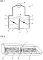
- Fig. 1 shows a ventilation device 1 for a motor vehicle with a first ventilation duct 2 and a first ventilation device opening 3, via which an air flow is guided into a motor vehicle interior.
- the ventilation device 1 has a second ventilation duct 4 and a second ventilation device opening 5, through which a further air flow is guided into the vehicle interior.
- the ventilation device 1 comprises a first closing device 6 and a second closing device 7, both of which are rotatably mounted, the first closing device 6 being configured to close the first ventilation duct 2 in its closed position by changing its degree of opening, and the second closing device 7 being configured to do so is to close the second ventilation duct 4 in its closed position by changing its degree of opening.
- an operating device 8 is arranged on the ventilation device 1, which has a first and a second degree of freedom A, B (see FIG Fig. 2 ).
- the operating device 8 is connected to a coupling device 10 via a mechanical movement coupling 9, the coupling device 10 in turn via a mechanical movement coupling 11 with the rotatably mounted first locking device 6 and via a mechanical one Movement coupling 12 is connected to the rotatably mounted second locking device 7, so that the coupling device 10 couples the first locking device 6 or the second locking device 7 with the operating device 8 as a function of an operation on the operating device 8.
- the mechanical movement coupling 9 is a rotatable shaft, the rotation of the shaft being able to be carried out by an operating action on the operating device 8 in accordance with the second degree of operating freedom B of the operating device 8.
- the coupling device 10 comprises two drive elements, one of which is coupled to the locking devices 6, 7.
- the position of the shaft can be adjusted such that the coupling device 10 connects the shaft either to the first of the drive elements and thus via the mechanical movement coupling 11 to the first locking device 6 or to the second of the drive elements and thus via the mechanical movement coupling 12 couples with the locking device 7.
- both locking devices 6, 7 can also be decoupled from the operating device 8, so that accidental actuation of the operating device 8 by a user or a vehicle occupant does not result in any adjustment of the locking devices 6, 7.
- Both the air flow guided through the first ventilation duct 2 and the air flow guided through the second ventilation duct 4 are generated by a central fan 13.
- Fig. 2 shows the already in Fig. 1 illustrated ventilation device 1 for a motor vehicle in a front view. Accordingly, the two ventilation device openings 3, 5 and the arrangement of the operating device 8 between the first ventilation device opening 3 and the second ventilation device opening 5 are shown.
- the operating device 8 can be adjusted according to its two operating degrees of freedom A, B, with the first operating degree of freedom A being able to select which of the closing devices 6, 7 is or are selected for the subsequent setting of the degree of opening by the second degree of operating freedom B and by means of the second degree of operating freedom B, the degree of opening of at least a selected one of the closing devices 6, 7 is adjustable.
- the operating device 8 is a rotary wheel which can be displaced according to the first degree of operating freedom A, whereby one of the locking devices 6, 7 can be selected.
- the operating wheel can be rotated in accordance with the second degree of operating freedom B, whereby the degree of opening of a closing device 6, 7 can be adjusted.
- the operating device in a middle position, which corresponds to a basic state of the operating device. From this basic state, the operating device can be adjusted according to the degrees of freedom A and B in the respective arrow direction in order to select at least one closing device 6, 7 for setting the opening degree, or respectively setting the opening degree of at least one selected one of the closing devices 6, 7.
- FIG. 2 The ventilation device 1 is shown in its installed state in a motor vehicle interior, the ventilation device 1 being embedded in a dashboard 14 of the motor vehicle and the operating device 8 thus being conveniently operated by both the driver and the front passenger.
- Fig. 3 shows a further embodiment of a ventilation device 15 with a first ventilation channel 16 and a first ventilation device opening 17 through which an air flow is guided into a motor vehicle interior.
- the ventilation device 15 comprises a second ventilation duct 18 and a second ventilation device opening 19, through which a further air flow is guided into the vehicle interior.
- a first closing device 20 in the form of a rotatably mounted flap is arranged in the first ventilation duct 16, so that the first ventilation duct 16 can be closed by the first closing device 20.
- a second closing device 21 also in the form of a arranged rotatably mounted flap, so that the second ventilation duct 18 can be closed by the second closing device 21.
- an operating device 22 is arranged, which has a sensor 23 for providing a sensor signal as a function of an operating input by a user.
- the sensor 23 is a sensor that detects the movements of a control wheel.
- the control wheel is rotatable on the one hand and adjustable in the transverse direction of the motor vehicle on the other hand.
- An operating action by a user in accordance with the first degree of operating freedom A can be carried out by adjusting the operating wheel in the axial direction or in the transverse direction of the motor vehicle.
- An operating action by a user in accordance with the second degree of operating freedom B can be carried out by rotating the operating wheel.
- the senor 23 could also be a touch-sensitive touch panel, with the aid of which a touch or a movement of a finger of a user in different directions can be detected.
- An operating action by a user in accordance with the first degree of operating freedom can be carried out by touching the touch panel with a finger and moving the finger in the transverse direction of the motor vehicle.
- An operating action by a user according to the second degree of operating freedom can be carried out by touching the touch panel with a finger and moving the finger in the vertical direction of the motor vehicle.
- a sensor signal generated by the sensor 23 as a function of the operating actions corresponding to the operating degrees of freedom is transmitted to a control device 31 and converted into a corresponding control signal by the control device 31. Then there is a wireless radio transmission of the control signal to the adjustment device 24.
- the adjustment device 24 comprises a first and a second actuator for adjusting the respective degree of opening of the first and second locking devices 20, 21. If a user performs an operating action corresponding to the first degree of freedom A of the operating wheel off, is through the Control device adapted as a function of the operator action which actuators of the adjustment device 24 are selected and this selection is stored.
- an opening degree signal is generated by the sensor 23 as a function of the rotation of the operating wheel.
- the opening degree signal is transmitted to the control device 31 and converted by this into opening degree control signals for the first and second actuators.
- the opening degree control signals are output only for those actuators that are assigned to the currently selected locking device or the currently selected locking devices.
- Both the air flow guided through the first ventilation duct 16 and the air flow guided through the second ventilation duct 18 are generated by a central fan 27.
- a lighting device 28 is arranged on the ventilation device 15 in such a way that two illuminants 29, 30 are located to the left and right of the operating device 22.
- a control device which is implemented together with the control device 31, controls the lighting device in such a way that, depending on which closing device 20, 21 is selected for adjusting the degree of opening, the corresponding illuminant 29, 30 emits visible light.
Landscapes
- Engineering & Computer Science (AREA)
- Mechanical Engineering (AREA)
- Physics & Mathematics (AREA)
- Thermal Sciences (AREA)
- Chemical & Material Sciences (AREA)
- Combustion & Propulsion (AREA)
- General Engineering & Computer Science (AREA)
- Air-Conditioning For Vehicles (AREA)
Description
- Die Erfindung betrifft eine Lüftungseinrichtung für ein Kraftfahrzeug mit einem ersten Lüftungskanal zum Führen eines ersten Luftstroms über eine erste Lüftungseinrichtungsöffnung in einen Kraftfahrzeuginnenraum, einem zweiten Lüftungskanal zum Führen eines zweiten Luftstroms über eine zweite Lüftungseinrichtungsöffnung in den Kraftfahrzeuginnenraum, und einer ersten und einer zweiten Schließvorrichtung, deren jeweiliger Öffnungsgrad durch eine Bedieneinrichtung zwischen einer Offen- und einer Schließstellung verstellbar ist, wobei die erste Schließvorrichtung in der Schließstellung den ersten Lüftungskanal und die zweite Schließvorrichtung in der Schließstellung den zweiten Lüftungskanal verschließt, wobei die Bedieneinrichtung wenigstens zwei Bedienfreiheitsgrade aufweist, wobei mittels des ersten Bedienfreiheitsgrades auswählbar ist, welche der Schließvorrichtungen zur nachfolgenden Einstellung des Öffnungsgrades durch den zweiten Bedienfreiheitsgrad ausgewählt ist oder sind, und mittels des zweiten Bedienfreiheitsgrades der Öffnungsgrad oder die Öffnungsgrade der ausgewählten Schließvorrichtung einstellbar ist oder sind. Daneben betrifft die Erfindung ein Kraftfahrzeug.
- Lüftungseinrichtungen dienen dazu, wenigstens einen Luftstrom in den Innenraum eines Kraftfahrzeugs zu leiten, um eine gezielte Belüftung respektive Klimatisierung des Kraftfahrzeuginnenraums zu ermöglichen. Üblicherweise werden in dem Kraftfahrzeug mehrere Belüftungseinrichtungen an unterschiedlichen Stellen angeordnet, um den Luftstrom möglichst gleichmäßig in dem Innenraum des Kraftfahrzeugs verteilen zu können.
- Typischerweise werden Lüftungseinrichtungen im Armaturenbrett, in der Mittelkonsole, in der Nähe der Seitenscheiben und/oder im Fußraum des Kraftfahrzeuginnenraums angeordnet. Im Allgemeinen steuern die Lüftungseinrichtungen sowohl den Volumenstrom als auch die Richtung eines Luftstroms. Üblicherweise umfasst eine Lüftungseinrichtung eine Bedieneinrichtung, wie beispielsweise ein Bedienrad oder einen Bedienhebel, um es einem Benutzer zu ermöglichen, eine gewünschte Luftmenge oder eine Richtung eines Luftstroms einzustellen. Beispielsweise kann der Luftstrom vom Benutzer in eine bestimmte Richtung verstellt, gedrosselt oder durch vollständiges Verschließen der an der Lüftungseinrichtung angeordneten Schließvorrichtung komplett gestoppt werden. Herkömmliche Lüftungseinrichtungen für Belüftungsvorrichtungen, die in Kraftfahrzeugen eingesetzt werden, weisen zumeist mehrere Bedieneinrichtungen auf, um unterschiedliche Einstellfunktionen der Lüftungseinrichtung zu ermöglichen. Bei zunehmendem Funktionsumfang derartiger Lüftungseinrichtungen ist daher eine Vereinfachung der Bedienung vorteilhaft.
-
DE 43 27 266 C1 offenbart eine Seitendüse zur Innenraumbelüftung eines Fahrzeugs, die zwei in eine gemeinsame Düseneintrittsöffnung mündende Düsenteile beinhaltet, umfassend eine dem ersten Düsenteil zugeordnete, luftmengenregulierende erste Klappe und eine dem zweiten Düsenteil zugeordnete, luftmengenregulierende zweite Klappe. Ferner sind fernbedienbare Mittel, mit denen die zweite Klappe in ihre Offenstellung bewegbar ist, und eine handbedienbare Einstelleinrichtung, mit der die erste Klappe verstellbar ist, vorgesehen. -
DE 10 2011 114 766 A1 offenbart ein Lüftungs- und Heizungsmodul für Kraftfahrzeuge mit wenigstens einem Lüftungskanal, wobei der Lüftungskanal in einem Luftausströmer im Innenraum des Kraftfahrzeugs endet und wobei wenigstens eine Luftklappe zur Veränderung des Durchtrittquerschnittes des Lüftungskanals vorgesehen ist. Zur Verstellung der Luftklappe steht ein Bedienrad mit der Luftklappe in Wirkverbindung. - Aus der Druckschrift
DE 10 2013 008 066 A1 ist eine Belüftungseinrichtung eines Fahrzeugs bekannt. Eine Sensorvorrichtung ist dazu eingerichtet, die Präsenz eines Objekts in einem vorbestimmten Bereich im Fahrzeuginnenraum zu erfassen und auf Basis der Position des Objekts eine Verstelleinrichtung zur Konfiguration des Luftstroms anzusteuern. Bei dem erfassten Objekt kann es sich insbesondere um eine Hand handeln. - Eine Bedieneinrichtung für ein Kraftfahrzeug, durch die in einer ersten Drehposition durch eine Lageveränderung eine erste Bedienfunktion bedienbar ist und durch die in einer zweiten Drehposition durch eine Lageveränderung wenigstens eine weitere Funktion der Bedieneinrichtung bedienbar ist, ist aus der Druckschrift
DE 10 2014 221 133 A1 bekannt. Beispielsweise kann die erste Drehposition zur Einstellung einer Temperatur und die zweite Drehposition zur Einstellung einer Gebläsedrehzahl nutzbar sein. - Die Aufgabe der Erfindung besteht darin, eine Lüftungseinrichtung mit einem verbesserten Bedienkonzept anzugeben.
- Zur Lösung dieser Aufgabe ist bei einer Lüftungseinrichtung der eingangs genannten Art erfindungsgemäß vorgesehen, dass der erste Bedienfreiheitsgrad einer linearen Bewegung oder einer Rotation der Bedieneinrichtung oder einer Komponente der Bedieneinrichtung in eine erste Bedienrichtung und der zweite Bedienfreiheitsgrad einer linearen Bewegung oder einer Rotation der Bedieneinrichtung oder der Komponente in eine gewinkelt zu der ersten Bedienrichtung stehende zweite Bedienrichtung entsprechen.
Die Bedieneinrichtung, welche an der Lüftungseinrichtung angeordnet sein kann, kann so verstellt werden, dass wahlweise der Öffnungsgrad der ersten Schließvorrichtung und/oder der zweiten Schließvorrichtung durch diese eine Bedieneinrichtung steuerbar sind. Die benötigte Anzahl unterschiedlicher Bedieneinrichtungen kann erfindungsgemäß reduziert werden, wodurch sich die Herstellungskosten der Lüftungseinrichtung reduzieren. Zudem kann dadurch, dass die Bedieneinrichtung sowohl für die Verstellung der ersten als auch der zweiten Schließvorrichtung ausgebildet ist, ein für einen Benutzer intuitives Bedienkonzept für die Lüftungseinrichtung realisiert werden. - Beispielsweise kann eine Bewegung der Bedieneinrichtung nach links oder rechts zur Auswahl der ersten oder der zweiten Schließvorrichtung dienen, während eine Bewegung der Bedieneinrichtung nach oben oder unten den
- Öffnungsgrad wenigstens einer Ausgewählten der Schließvorrichtungen steuern kann. Somit lassen sich die erste und die zweite Schließvorrichtung selektiv auswählen und ihr jeweiliger Öffnungsgrad einstellen, wobei es möglich ist, dass durch die Bedieneinrichtung auch mehrere respektive alle Schließvorrichtungen und/oder keine der Schließvorrichtungen zur Verstellung des Öffnungsgrades ausgewählt werden können.
- Die Bedieneinrichtung kann an der Lüftungseinrichtung zwischen der ersten und der zweiten Lüftungseinrichtungsöffnung angeordnet sein. Bei einer Bewegung der Bedieneinrichtung gemäß dem ersten Bedienfreiheitsgrad kann sich ihr Abstand zu einer der Lüftungseinrichtungsöffnungen verkleinern und ihr Abstand zu der anderen Lüftungseinrichtungsöffnung gleichzeitig vergrößern. Hierbei kann ein besonders intuitives Bedienkonzept realisiert werden, wenn jene Schließvorrichtung ausgewählt wird, die der Lüftungseinrichtungsöffnung zugeordnet ist, in deren Richtung die Bedieneinrichtung bewegt wird.
- Die Bedieneinrichtung kann in einer von mehreren Verstellpositionen verrasten, wenn sie von einem Benutzer entsprechend des ersten Bedienfreiheitsgrades betätigt wird. Andererseits ist es allerdings auch möglich, dass die Bedieneinrichtung entgegen einer Rückstellkraft betätigbar ist und dementsprechend unmittelbar nach der Betätigung durch einen Benutzer in ihre Ausgangsposition zurückverstellt wird. Die durch die Betätigung erfolgte Auswahl der zu verstellenden Schließvorrichtung kann in einer Steuereinrichtung gespeichert werden oder es kann durch die Betätigung eine mechanische Konfiguration der Lüftungseinrichtung verändert werden, um den zweiten Bedienfreiheitsgrad der Bedieneinrichtung mit der ersten und/oder der zweiten Schließvorrichtung zu koppeln bzw. von dieser zu entkoppeln.
- Die Lüftungseinrichtung kann eine Beleuchtungseinrichtung und ein die Beleuchtungseinrichtung steuerndes Steuergerät aufweisen, wobei das Steuergerät eingerichtet ist, die Beleuchtungseinrichtung in Abhängigkeit der ausgewählten Schließvorrichtung zur Gabe eines optischen Signals anzusteuern. Anhand des ausgegebenen optischen Signals kann für einen Benutzer erkennbar sein, welche der Schließvorrichtungen ausgewählt ist bzw. sind. Die optischen Signale können sich hinsichtlich ihrer Helligkeit und/oder ihrer Farbe unterscheiden, wobei die Beleuchtungseinrichtung auch mehrere Leuchtmittel aufweisen kann, die durch eine entsprechende Anordnung an der Lüftungseinrichtung eine Zuordnung des jeweiligen Leuchtmittels zu einer Schließvorrichtung erkennen lassen. Eine bevorzugte Variante der Erfindung kann vorsehen, dass ein einer Schließvorrichtung zugeordnetes Leuchtmittel sichtbares Licht ausgibt, wenn die dem Leuchtmittel zugeordnete Schließvorrichtung durch die Bedieneinrichtung ausgewählt ist, und kein Licht ausgibt, wenn die zugeordnete Schließvorrichtung nicht ausgewählt ist.
- Eine Variante der Erfindung kann vorsehen, dass die Lüftungseinrichtung eine Kopplungseinrichtung aufweist, die das Bedienelement mit der ausgewählten Schließvorrichtung oder den ausgewählten Schließvorrichtungen mechanisch bewegungskoppelt. Da im Rahmen der Erfindung eine selektive Auswahl einer oder mehrerer Schließvorrichtungen vorgesehen ist, kann die Kopplungseinrichtung eine mechanische Verbindung zu keiner, einer oder zu mehreren Schließvorrichtungen herstellen. Die mechanische Kopplung kann beispielsweise über eine Bedienhandlung am ersten Bedienfreiheitsgrad einer Welle erfolgen, deren Lage durch eine Bedienhandlung am ersten Bedienfreiheitsgrad zwischen zwei Positionen verstellbar ist, in denen sie mit jeweils einer der Schließvorrichtungen mittels der Kopplungseinrichtung gekoppelt ist. Die Kopplungseinrichtung kann dazu eingerichtet sein, einzelne Schließvorrichtungen zu koppeln oder zu entkoppeln. Eine Betätigung der Bedieneinrichtung gemäß des zweiten Bedienfreiheitsgrades, beispielsweise eine Drehbewegung, kann über die mechanische Welle an die Kopplungseinrichtung übertragen und an die ausgewählte Verstelleinrichtung gegeben werden, um deren Öffnungsgrad zu verstellen.
- Erfindungsgemäß kann die Lüftungseinrichtung eine Verstelleinrichtung, die zur separaten Verstellung des Öffnungsgrades der ersten und der zweiten Schließvorrichtung in Abhängigkeit eines Steuersignals eingerichtet ist, und eine Steuereinrichtung, die zur Bereitstellung des Steuersignals in Abhängigkeit von einer über wenigstens einen Sensor der Bedieneinrichtung erfassten Bedieneingabe eingerichtet ist, umfassen. Es ist möglich, dass die vom Sensor erfasste Bedieneingabe per drahtloser Funkübertragung an die Steuereinrichtung übertragbar ist. Die Verstelleinrichtung kann mehrere Aktoren aufweisen, die dazu eingerichtet sind, in Abhängigkeit des Steuersignals der Steuereinrichtung jeweils eine der Schließvorrichtung zu verstellen. Die Steuereinrichtung kann für die Aktoren separate Steuersignale vorgeben. Hierzu kann die Steuereinrichtung Bedieneingaben gemäß des ersten Bedienfreiheitsgrades erfassen und in Abhängigkeit der erfassten Bedieneingaben bestimmen, welche der Verstelleinrichtungen ausgewählt sind und diese Information speichern. Bei einer Erfassung einer Bedieneingabe gemäß des zweiten Bedienfreiheitsgrades kann die Steuereinrichtung ein Steuersignal für jene Aktoren ermitteln, die der ausgewählten Schließvorrichtung oder den ausgewählten Schließvorrichtungen zugeordnet sind, und es an diese ausgeben. Dementsprechend kann erfindungsgemäß auch eine mittels eines Sensors erfasste Bedieneingabe entsprechend eines ersten und zweiten Bedienfreiheitsgrads ausgewertet werden, wobei der erste Bedienfreiheitsgrad zur Auswahl wenigstens einer der Schließvorrichtungen und der zweite Bedienfreiheitsgrad zur Verstellung des Öffnungsgrads der Schließvorrichtung dient.
- Der erste Bedienfreiheitsgrad entspricht einer linearen Bewegung oder einer Rotation der Bedieneinrichtung oder einer Komponente der Bedieneinrichtung in eine erste Bedienrichtung und der zweite Bedienfreiheitsgrad entspricht einer linearen Bewegung oder einer Rotation der Bedieneinrichtung oder der Komponente in eine gewinkelt, insbesondere senkrecht, zu der ersten Bedienrichtung stehende zweite Bedienrichtung. Insbesondere kann einer der Bedienfreiheitsgrade einer Rotation der Bedieneinrichtung oder der Komponente um eine Achse entsprechen und der andere einer Bewegung parallel zu dieser Achse. Eine der Bedienrichtungen bzw. die Achse kann im Einbauzustand in die Querrichtung des Kraftfahrzeugs und/oder in Richtung einer Verbindungslinie der Lüftungseinrichtungsöffnungen verlaufen.
- Neben der erfindungsgemäßen Lüftungseinrichtung betrifft die Erfindung ein Kraftfahrzeug mit wenigstens einer erfindungsgemäßen Lüftungseinrichtung.
- Das Kraftfahrzeug kann ein Steuergerät aufweisen, das zur Ansteuerung einer Anzeigevorrichtung zur Anzeige einer den Öffnungsgrad wenigstens einer der Schließvorrichtungen und/oder die Auswahl einer oder mehrerer der Schließvorrichtungen beschreibenden Information ausgebildet ist. Das Steuergerät des Kraftfahrzeugs kann identisch zu dem in Verbindung mit der Beleuchtungseinrichtung der Lüftungseinrichtung genannten Steuergerät oder separat von diesem ausgebildet sein.
- Bei einer mittels der Anzeigevorrichtung erzeugten Darstellung kann es sich um die Darstellung einer Information handeln, die einen Zustand der Bedieneinrichtung beschreibt und/oder die angibt, welche der Schließvorrichtungen ausgewählt ist oder sind und/oder die den Öffnungsgrad einer oder mehrerer der ausgewählten Schließvorrichtungen und/oder einer oder mehrerer der nicht ausgewählten Schließvorrichtungen anzeigt. Durch eine entsprechende Anordnung der Anzeigevorrichtung im Innenraum des Kraftfahrzeugs kann erreicht werden, dass der Fahrer durch eine Bedienung der Lüftungseinrichtung nicht von dem Führen des Kraftfahrzeugs abgelenkt wird, da ihm alle relevanten Informationen mittels der Anzeigevorrichtung dargestellt werden.
- Erfindungsgemäß kann die Bedienungseinrichtung zwischen der ersten und der zweiten Lüftungseinrichtungsöffnung entweder an der Lüftungseinrichtung oder einer Komponente des Fahrzeuginnenraums angeordnet sein. Es liegt im Rahmen der Erfindung, dass mehrere Lüftungseinrichtungen, die an unterschiedlichen Stellen im Kraftfahrzeuginnenraum angeordnet sind, mittels einer Bedieneinrichtung steuerbar sind, obwohl sie nicht in einem gemeinsamen Gehäuse eingebettet sind.
- Erfindungsgemäß kann der erste Bedienfreiheitsgrad einer Bewegung der Bedieneinrichtung, oder einer Komponente der Bedieneinrichtung in Querrichtung des Kraftfahrzeugs entsprechen.
- Weitere Vorteile und Einzelheiten der Erfindung werden nachfolgend anhand von Ausführungsbeispielen unter Bezugnahme auf die Zeichnungen erläutert. Die Zeichnungen zeigen schematisch:
- Fig. 1
- eine erfindungsgemäße Lüftungseinrichtung in einer geschnittenen Draufsicht;
- Fig. 2
- die in
Fig. 1 gezeigte Lüftungseinrichtung in einer Frontalansicht; und - Fig. 3
- ein weiteres Ausführungsbeispiel einer erfindungsgemäßen Lüftungseinrichtung in einer geschnittenen Draufsicht.
-
Fig. 1 zeigt eine Lüftungseinrichtung 1 für ein Kraftfahrzeug mit einem ersten Lüftungskanal 2 und einer ersten Lüftungseinrichtungsöffnung 3, über die ein Luftstrom in einen Kraftfahrzeuginnenraum geführt wird. Zudem weist die Lüftungseinrichtung 1 einen zweiten Lüftungskanal 4 und eine zweite Lüftungseinrichtungsöffnung 5 auf, durch die ein weiterer Luftstrom in den Kraftfahrzeuginnenraum geführt wird. Die Lüftungseinrichtung 1 umfasst eine erste Schließvorrichtung 6 und eine zweite Schließvorrichtung 7, die beide drehbar gelagert sind, wobei die erste Schließvorrichtung 6 dazu eingerichtet ist, durch Änderung ihres Öffnungsgrads den ersten Lüftungskanal 2 in ihrer Schließstellung zu verschließen, und die zweite Schließvorrichtung 7 dazu eingerichtet ist, durch Ändern ihres Öffnungsgrads den zweiten Lüftungskanal 4 in ihrer Schließstellung zu verschließen. Damit es einem Benutzer respektive einem Fahrzeuginsassen ermöglicht wird, die Schließvorrichtungen 6, 7 zu steuern, ist an der Lüftungseinrichtung 1 eine Bedieneinrichtung 8 angeordnet, die einen ersten und einen zweiten Bedienfreiheitsgrad A, B aufweist (sieheFig. 2 ). - Die Bedieneinrichtung 8 ist über eine mechanische Bewegungskopplung 9 mit einer Kopplungseinrichtung 10 verbunden, wobei die Kopplungseinrichtung 10 wiederum über eine mechanische Bewegungskopplung 11 mit der drehbar gelagerten ersten Schließvorrichtung 6 und über eine mechanische Bewegungskopplung 12 mit der drehbar gelagerten zweiten Schließvorrichtung 7 verbunden ist, so dass die Kopplungseinrichtung 10 in Abhängigkeit einer Bedienung an der Bedieneinrichtung 8 die erste Schließvorrichtung 6 oder die zweite Schließvorrichtung 7 mit der Bedieneinrichtung 8 bewegungskoppelt. Die mechanische Bewegungskopplung 9 ist eine drehbare Welle, wobei das Drehen der Welle durch eine Bedienhandlung an der Bedieneinrichtung 8 entsprechend des zweiten Bedienfreiheitsgrades B der Bedieneinrichtung 8 durchführbar ist. Die Kopplungseinrichtung 10 umfasst zwei Antriebselemente, von denen jeweils ein Antriebselement mit den Schließvorrichtungen 6, 7 gekoppelt ist. Durch Betätigung der Bedieneinrichtung gemäß dem ersten Bedienfreiheitsgrad A ist die Lage der Welle derart verstellbar, dass die Kopplungseinrichtung 10 die Welle entweder mit dem ersten der Antriebselemente und somit über die mechanische Bewegungskopplung 11 mit der ersten Schließvorrichtung 6 oder mit dem zweiten der Antriebselemente und somit über die mechanische Bewegungskopplung 12 mit der Schließvorrichtung 7 koppelt.
- Mittels der Kopplungseinrichtung 10 können auch beide Schließvorrichtungen 6, 7 von der Bedieneinrichtung 8 entkoppelt werden, so dass eine versehentliche Betätigung der Bedieneinrichtung 8 durch einen Benutzer respektive einen Fahrzeuginsassen keine Verstellung der Schließvorrichtungen 6, 7 zur Folge hat. Sowohl der durch den ersten Lüftungskanal 2 geführte Luftstrom als auch der durch den zweiten Lüftungskanal 4 geführte Luftstrom wird durch ein zentrales Gebläse 13 erzeugt.
-
Fig. 2 zeigt die bereits inFig. 1 dargestellte Lüftungseinrichtung 1 für ein Kraftfahrzeug in einer frontalen Ansicht. Demnach sind die beiden Lüftungseinrichtungsöffnungen 3, 5 und die Anordnung der Bedieneinrichtung 8 zwischen der ersten Lüftungseinrichtungsöffnung 3 und der zweiten Lüftungseinrichtungsöffnung 5 dargestellt. Die Bedieneinrichtung 8 kann entsprechend ihrer zwei Bedienfreiheitsgrade A, B verstellt werden, wobei mittels des ersten Bedienfreiheitsgrades A auswählbar ist, welche der Schließvorrichtungen 6, 7 zur nachfolgenden Einstellung des Öffnungsgrades durch den zweiten Bedienfreiheitsgrad B ausgewählt ist oder sind und mittels des zweiten Bedienfreiheitsgrades B der Öffnungsgrad wenigstens einer Ausgewählten der Schließvorrichtungen 6, 7 einstellbar ist. Im Rahmen des gezeigten Ausführungsbeispiels handelt es sich bei der Bedieneinrichtung 8 um ein Drehrad, das entsprechend des ersten Bedienfreiheitsgrades A verschiebbar ist, wodurch eine der Schließvorrichtungen 6, 7 auswählbar ist. Zudem ist das Bedienrad entsprechend des zweiten Bedienfreiheitsgrades B drehbar, wodurch der Öffnungsgrad einer Schließvorrichtung 6, 7 einstellbar ist. - Wie in
Fig. 2 dargestellt befindet sich die Bedieneinrichtung in einer mittleren Stellung, die einem Grundzustand der Bedieneinrichtung entspricht. Aus diesem Grundzustand kann die Bedieneinrichtung entsprechend der Freiheitsgrade A und B, in der jeweiligen Pfeilrichtung verstellt werden, um wenigstens eine Schließvorrichtung 6, 7 zur Einstellung des Öffnungsgrades auszuwählen, respektive den Öffnungsgrad wenigstens einer Ausgewählten der Schließvorrichtungen 6, 7 einzustellen. - In
Fig. 2 ist die Lüftungseinrichtung 1 in ihrem verbauten Zustand in einem Kraftfahrzeuginnenraum gezeigt, wobei die Lüftungseinrichtung 1 in ein Armaturenbrett 14 des Kraftfahrzeugs eingebettet ist und die Bedieneinrichtung 8 somit bequem sowohl vom Fahrer als auch vom Beifahrer bedient werden kann. -
Fig. 3 zeigt ein weiteres Ausführungsbeispiel einer Lüftungseinrichtung 15 mit einem ersten Lüftungskanal 16 und einer ersten Lüftungseinrichtungseinrichtungsöffnung 17, durch die ein Luftstrom in einen Kraftfahrzeuginnenraum geführt wird. Zudem umfasst die Lüftungseinrichtung 15, wie bereits im vorangegangenen Ausführungsbeispiel, einen zweiten Lüftungskanal 18 und eine zweite Lüftungseinrichtungsöffnung 19, durch die ein weiterer Luftstrom in den Kraftfahrzeuginnenraum geführt wird. - Im ersten Lüftungskanal 16 ist eine erste Schließvorrichtung 20 in Form einer drehbar gelagerten Klappe angeordnet, so dass durch die erste Schließvorrichtung 20 der erste Lüftungskanal 16 verschließbar ist. In dem zweiten Lüftungskanal 18 ist eine zweite Schließvorrichtung 21, ebenfalls in Form einer drehbar gelagerten Klappe angeordnet, so dass durch die zweite Schließvorrichtung 21 der zweite Lüftungskanal 18 verschließbar ist. An einem im verbauten Zustand zugänglichen Ende der Lüftungseinrichtung 15 ist eine Bedieneinrichtung 22 angeordnet, die zur Bereitstellung eines Sensorsignals in Abhängigkeit einer Bedieneingabe eines Benutzers einen Sensor 23 aufweist. Bei dem Sensor 23 handelt es sich um einen Sensor, der Bewegungen eines Bedienrades erfasst. Das Bedienrad ist einerseits rotierbar und andererseits in Querrichtung des Kraftfahrzeugs verstellbar. Eine Bedienhandlung eines Benutzers gemäß des ersten Bedienfreiheitsgrades A ist durch Verstellen des Bedienrades in axialer Richtung respektive in Querrichtung des Kraftfahrzeugs ausführbar. Eine Bedienhandlung eines Benutzers gemäß des zweiten Bedienfreiheitsgrades B ist durch Rotation des Bedienrades ausführbar.
- Der Sensor 23 könnte in einem alternativen Ausführungsbeispiel auch ein berührungsempfindliches Touchpanel sein, mithilfe dessen eine Berührung respektive eine Bewegung eines Fingers eines Benutzers in unterschiedliche Richtungen erfassbar ist. Eine Bedienhandlung eines Benutzers gemäß des ersten Bedienfreiheitsgrades ist durch eine Berührung des Touchpanels mit einem Finger und Bewegung des Fingers in Querrichtung des Kraftfahrzeugs ausführbar. Eine Bedienhandlung eines Benutzers gemäß des zweiten Bedienfreiheitsgrades hingegen ist durch eine Berührung des Touchpanels mit einem Finger und Bewegung des Fingers in Hochrichtung des Kraftfahrzeugs ausführbar.
- Ein von dem Sensor 23 in Abhängigkeit der den Bedienfreiheitsgraden entsprechenden Bedienhandlungen erzeugtes Sensorsignal wird an eine Steuereinrichtung 31 übertragen und durch die Steuereinrichtung 31 in ein korrespondierendes Steuersignal umgesetzt. Anschließend erfolgt eine drahtlose Funkübertragung des Steuersignals an die Verstelleinrichtung 24. Die Verstelleinrichtung 24 umfasst einen ersten und einen zweiten Aktor zur Verstellung des jeweiligen Öffnungsgrads der ersten bzw. der zweiten Schließvorrichtung 20, 21. Führt ein Benutzer eine Bedienhandlung entsprechend des ersten Bedienfreiheitsgrades A des Bedienrades aus, wird durch die Steuereinrichtung in Abhängigkeit der Bedienhandlung angepasst, welche Aktoren der Verstelleinrichtung 24 ausgewählt sind und diese Auswahl wird gespeichert.
- Führt ein Benutzer eine Bedienhandlung entsprechend des zweiten Bedienfreiheitsgrades B des Bedienrades aus, wird vom Sensor 23 in Abhängigkeit der Rotation des Bedienrades ein Öffnungsgradsignal erzeugt. Das Öffnungsgradsignal wird an die Steuereinrichtung 31 übertragen und von dieser in Öffnungsgradsteuersignale für den ersten und zweiten Aktor umgesetzt. Die Ausgabe der Öffnungsgradsteuersignale erfolgt nur für jene Aktoren, die der momentan ausgewählten Schließvorrichtung oder den momentan ausgewählten Schließvorrichtungen zugeordnet ist oder sind.
- Sowohl der durch den ersten Lüftungskanal 16 geführte Luftstrom als auch der durch den zweiten Lüftungskanal 18 geführte Luftstrom wird durch ein zentrales Gebläse 27 erzeugt. Eine Beleuchtungseinrichtung 28 ist derart an der Lüftungseinrichtung 15 angeordnet, dass sich zwei Leuchtmittel 29, 30 links und rechts von der Bedieneinrichtung 22 befinden. Ein Steuergerät, das gemeinsam mit der Steuereinrichtung 31 implementiert ist, steuert die Beleuchtungseinrichtung derart an, dass je nachdem welche Schließeinrichtung 20, 21 zur Verstellung des Öffnungsgrads ausgewählt ist, das entsprechende Leuchtmittel 29, 30 sichtbares Licht ausgibt.
Claims (9)
- Lüftungseinrichtung (1, 15) für ein Kraftfahrzeug mit einem ersten Lüftungskanal (2, 16) zum Führen eines ersten Luftstroms über eine erste Lüftungseinrichtungsöffnung (3, 17) in einen Kraftfahrzeuginnenraum, einem zweiten Lüftungskanal (4, 18) zum Führen eines zweiten Luftstroms über eine zweite Lüftungseinrichtungsöffnung (5, 19) in den Kraftfahrzeuginnenraum, und einer ersten und einer zweiten Schließvorrichtung (6, 20, 7, 21), deren jeweiliger Öffnungsgrad durch eine Bedieneinrichtung (8, 22) zwischen einer Offen- und einer Schließstellung verstellbar ist, wobei die erste Schließvorrichtung (6, 20) in der Schließstellung den ersten Lüftungskanal (2, 16) und die zweite Schließvorrichtung (7, 21) in der Schließstellung den zweiten Lüftungskanal (4, 18) verschließt, wobei die Bedieneinrichtung (8, 22) wenigstens zwei Bedienfreiheitsgrade (A, B) aufweist, wobei mittels des ersten Bedienfreiheitsgrades (A) auswählbar ist, welche der Schließvorrichtungen (6, 20, 7, 21) zur nachfolgenden Einstellung des Öffnungsgrades durch den zweiten Bedienfreiheitsgrad (B) ausgewählt ist oder sind, und mittels des zweiten Bedienfreiheitsgrades (B) der Öffnungsgrad oder die Öffnungsgrade der ausgewählten Schließvorrichtung (6, 20, 7, 21) einstellbar ist oder sind,
dadurch gekennzeichnet,
dass der erste Bedienfreiheitsgrad (A) einer linearen Bewegung oder einer Rotation der Bedieneinrichtung (8, 22) oder einer Komponente der Bedieneinrichtung (8, 22) in eine erste Bedienrichtung und der zweite Bedienfreiheitsgrad (B) einer linearen Bewegung oder einer Rotation der Bedieneinrichtung (8, 22) oder der Komponente in eine gewinkelt zu der ersten Bedienrichtung stehende zweite Bedienrichtung entsprechen. - Lüftungseinrichtung nach Anspruch 1,
dadurch gekennzeichnet,
dass die Bedieneinrichtung (8, 22) an der Lüftungseinrichtung (1, 15) zwischen der ersten und der zweiten Lüftungseinrichtungsöffnung (3, 17, 5, 19) angeordnet ist. - Lüftungseinrichtung nach Anspruch 1 oder 2,
dadurch gekennzeichnet,
dass sie eine Beleuchtungseinrichtung (28) und ein die Beleuchtungseinrichtung steuerndes Steuergerät aufweist, wobei das Steuergerät eingerichtet ist, die Beleuchtungseinrichtung (28) in Abhängigkeit der ausgewählten Schließvorrichtung (20, 21) zur Gabe eines optischen Signals anzusteuern. - Lüftungseinrichtung nach einem der vorangehenden Ansprüche,
dadurch gekennzeichnet,
dass es eine Kopplungseinrichtung (10) aufweist, die die Bedieneinrichtung (8) mit der ausgewählten Schließvorrichtung (6, 7) oder den ausgewählten Schließvorrichtungen (6, 7) mechanisch bewegungskoppelt. - Lüftungseinrichtung nach einem der Ansprüche 1 bis 3,
dadurch gekennzeichnet,
dass sie eine Verstelleinrichtung (24), die zur separaten Verstellung des Öffnungsgrades der ersten und der zweiten Schließvorrichtung in Abhängigkeit eines Steuersignals eingerichtet ist, und eine Steuereinrichtung (31), die zur Bereitstellung des Steuersignals in Abhängigkeit von einer über wenigstens einen Sensor (23) der Bedieneinrichtung (22) erfassten Bedieneingabe eingerichtet ist, umfasst. - Kraftfahrzeug,
dadurch gekennzeichnet,
dass es wenigstens eine Lüftungseinrichtung (1, 15) nach Anspruch 1 oder nach einem der Ansprüche 3 bis 5 umfasst. - Kraftfahrzeug nach Anspruch 6,
dadurch gekennzeichnet,
dass es ein Steuergerät aufweist, das zur Ansteuerung einer Anzeigevorrichtung zur Anzeige einer den Öffnungsgrad wenigstens einer der Schließvorrichtungen (6, 20, 7, 21) und/oder die Auswahl einer oder mehrerer der Schließvorrichtungen (6, 20, 7, 21) beschreibenden Information ausgebildet ist. - Kraftfahrzeug nach Anspruch 6 oder 7,
dadurch gekennzeichnet,
dass die Bedieneinrichtung (8, 22) zwischen der ersten und der zweiten Lüftungseinrichtungsöffnungen (3, 17, 5, 19) entweder an der Lüftungseinrichtung (1, 15) oder an einer Komponente des Fahrzeuginnenraums angeordnet ist. - Kraftfahrzeug nach einem der Ansprüche 6 bis 8,
dadurch gekennzeichnet,
dass der erste Bedienfreiheitsgrad (A) einer Bewegung der Bedieneinrichtung, oder einer Komponente der Bedieneinrichtung in Querrichtung des Kraftfahrzeugs entspricht.
Applications Claiming Priority (2)
| Application Number | Priority Date | Filing Date | Title |
|---|---|---|---|
| DE102016004992.8A DE102016004992B3 (de) | 2016-04-25 | 2016-04-25 | Lüftungseinrichtung für ein Kraftfahrzeug und zugehöriges Kraftfahrzeug |
| PCT/EP2017/000206 WO2017186321A1 (de) | 2016-04-25 | 2017-02-14 | Lüftungseinrichtung für ein kraftfahrzeug und zugehöriges kraftfahrzeug |
Publications (2)
| Publication Number | Publication Date |
|---|---|
| EP3448700A1 EP3448700A1 (de) | 2019-03-06 |
| EP3448700B1 true EP3448700B1 (de) | 2020-10-07 |
Family
ID=58046617
Family Applications (1)
| Application Number | Title | Priority Date | Filing Date |
|---|---|---|---|
| EP17705311.3A Active EP3448700B1 (de) | 2016-04-25 | 2017-02-14 | Lüftungseinrichtung für ein kraftfahrzeug und zugehöriges kraftfahrzeug |
Country Status (4)
| Country | Link |
|---|---|
| EP (1) | EP3448700B1 (de) |
| CN (1) | CN109070689B (de) |
| DE (1) | DE102016004992B3 (de) |
| WO (1) | WO2017186321A1 (de) |
Families Citing this family (2)
| Publication number | Priority date | Publication date | Assignee | Title |
|---|---|---|---|---|
| CN110978961A (zh) * | 2019-12-03 | 2020-04-10 | 常熟市汽车饰件股份有限公司 | 后置双摆车辆出风口调节结构 |
| CN116587813A (zh) * | 2022-07-01 | 2023-08-15 | 北京车和家汽车科技有限公司 | 可变风道系统及车辆 |
Family Cites Families (8)
| Publication number | Priority date | Publication date | Assignee | Title |
|---|---|---|---|---|
| DE4327266C1 (de) * | 1993-08-13 | 1994-08-25 | Daimler Benz Ag | Luftdüse |
| DE102011114766B4 (de) * | 2011-10-01 | 2014-09-04 | Audi Ag | Lüftungs- und Heizungsmodul für Kraftfahrzeuge mit wenigstens einem Luftführungskanal |
| DE102013008066B4 (de) * | 2013-05-10 | 2026-03-19 | Volkswagen Aktiengesellschaft | Belüftungseinrichtung |
| KR101409532B1 (ko) * | 2013-06-05 | 2014-06-19 | 주식회사 니프코코리아 | 자동차 에어벤트의 듀얼 댐퍼 장치 |
| CN104015588B (zh) * | 2014-06-11 | 2016-06-08 | 安徽江淮汽车股份有限公司 | 一种带除霜与吹面的多功能出风口总成 |
| DE102014221133A1 (de) * | 2014-10-17 | 2016-04-21 | Volkswagen Aktiengesellschaft | Bedieneinrichtung in einem Kraftfahrzeug |
| DE102015004062A1 (de) * | 2015-03-28 | 2015-08-27 | Daimler Ag | Luftzufuhreinrichtung für eine Klimatisierungsvorrichtung in einem Kraftfahrzeug |
| DE202015106878U1 (de) * | 2015-12-17 | 2016-01-15 | Ford Global Technologies, Llc | Luftausströmer für Heizungs- und Belüftungs- oder Klimaanlagen von Kraftfahrzeugen |
-
2016
- 2016-04-25 DE DE102016004992.8A patent/DE102016004992B3/de not_active Expired - Fee Related
-
2017
- 2017-02-14 CN CN201780025565.7A patent/CN109070689B/zh active Active
- 2017-02-14 WO PCT/EP2017/000206 patent/WO2017186321A1/de not_active Ceased
- 2017-02-14 EP EP17705311.3A patent/EP3448700B1/de active Active
Non-Patent Citations (1)
| Title |
|---|
| None * |
Also Published As
| Publication number | Publication date |
|---|---|
| DE102016004992B3 (de) | 2017-05-11 |
| WO2017186321A1 (de) | 2017-11-02 |
| CN109070689B (zh) | 2022-09-06 |
| EP3448700A1 (de) | 2019-03-06 |
| CN109070689A (zh) | 2018-12-21 |
Similar Documents
| Publication | Publication Date | Title |
|---|---|---|
| EP1809928B1 (de) | Betätigungseinrichtung mit drehschalter | |
| EP0888916B1 (de) | Lamellensystem für Belüftungseinrichtungen zur Regelung des Luftstroms, insbesondere für Belüftungen in Kraftfahrzeugen | |
| EP2552726B1 (de) | Vorrichtung zur bedienung unterschiedlicher funktionen eines kraftfahrzeugs | |
| DE102014203511B3 (de) | Luftausströmer für ein Fahrzeug | |
| DE102014105273B3 (de) | Einrichtung zum Verstellen von Lamellen eines Luftausströmers | |
| EP2670615B1 (de) | Vorrichtung zur bedienung mehrerer unterschiedlicher funktionen eines kraftfahrzeugs | |
| DE102016220671B4 (de) | Luftausströmer für Heizungs- und Belüftungs- oder Klimaanlagen von Kraftfahrzeugen | |
| EP1520738B1 (de) | Lamellendüse, insbesondere für eine Klimaanlage eines Kraftfahrzeugs | |
| EP3381725B1 (de) | Luftausströmer | |
| DE102015218309B4 (de) | Belüftungsdüse zur Belüftung eines Fahrzeuginnenraums | |
| DE102016013353A1 (de) | Ausströmer für ein Kraftfahrzeug und zugehöriges Kraftfahrzeug | |
| DE102011106784A1 (de) | Bedieneinheit für eine Funktionseinrichtung und Fahrzeug mit einer solchen Bedieneinheit, insbesondere zum Bedienen einer Klimatisierungsanlage | |
| WO2020234031A1 (de) | Luftauslasseinheit für eine fahrzeuglüftung und fahrzeug | |
| DE102021111535A1 (de) | Luftausströmeranordnung | |
| DE102019132921B4 (de) | Luftausströmer mit Bedieneinrichtung | |
| DE102016004992B3 (de) | Lüftungseinrichtung für ein Kraftfahrzeug und zugehöriges Kraftfahrzeug | |
| DE202005012570U1 (de) | Luftdüse | |
| WO2020160960A1 (de) | Bedieneinrichtung für ein verschwenkbar gelagertes luftleitelement | |
| DE202015106878U1 (de) | Luftausströmer für Heizungs- und Belüftungs- oder Klimaanlagen von Kraftfahrzeugen | |
| EP3478534B1 (de) | Verfahren und vorrichtung zum steuern der klimatisierung eines fahrzeugsitzes | |
| DE102019121738A1 (de) | Bedieneinrichtung für ein verschwenkbar gelagertes Luftleitelement und Luftausströmer mit Bedieneinrichtung | |
| DE102014221133A1 (de) | Bedieneinrichtung in einem Kraftfahrzeug | |
| DE102010031085A1 (de) | Luftausströmer | |
| EP3553626B1 (de) | Bedieneinrichtung | |
| DE19750160A1 (de) | Innenluft/Außenluft-Schaltvorrichtung mit Staudruck-Regeleinheit für eine Klimaanlage für ein Fahrzeug |
Legal Events
| Date | Code | Title | Description |
|---|---|---|---|
| STAA | Information on the status of an ep patent application or granted ep patent |
Free format text: STATUS: UNKNOWN |
|
| STAA | Information on the status of an ep patent application or granted ep patent |
Free format text: STATUS: THE INTERNATIONAL PUBLICATION HAS BEEN MADE |
|
| PUAI | Public reference made under article 153(3) epc to a published international application that has entered the european phase |
Free format text: ORIGINAL CODE: 0009012 |
|
| STAA | Information on the status of an ep patent application or granted ep patent |
Free format text: STATUS: REQUEST FOR EXAMINATION WAS MADE |
|
| 17P | Request for examination filed |
Effective date: 20181126 |
|
| AK | Designated contracting states |
Kind code of ref document: A1 Designated state(s): AL AT BE BG CH CY CZ DE DK EE ES FI FR GB GR HR HU IE IS IT LI LT LU LV MC MK MT NL NO PL PT RO RS SE SI SK SM TR |
|
| AX | Request for extension of the european patent |
Extension state: BA ME |
|
| DAV | Request for validation of the european patent (deleted) | ||
| DAX | Request for extension of the european patent (deleted) | ||
| STAA | Information on the status of an ep patent application or granted ep patent |
Free format text: STATUS: EXAMINATION IS IN PROGRESS |
|
| 17Q | First examination report despatched |
Effective date: 20191122 |
|
| GRAP | Despatch of communication of intention to grant a patent |
Free format text: ORIGINAL CODE: EPIDOSNIGR1 |
|
| STAA | Information on the status of an ep patent application or granted ep patent |
Free format text: STATUS: GRANT OF PATENT IS INTENDED |
|
| INTG | Intention to grant announced |
Effective date: 20200728 |
|
| GRAS | Grant fee paid |
Free format text: ORIGINAL CODE: EPIDOSNIGR3 |
|
| GRAA | (expected) grant |
Free format text: ORIGINAL CODE: 0009210 |
|
| STAA | Information on the status of an ep patent application or granted ep patent |
Free format text: STATUS: THE PATENT HAS BEEN GRANTED |
|
| AK | Designated contracting states |
Kind code of ref document: B1 Designated state(s): AL AT BE BG CH CY CZ DE DK EE ES FI FR GB GR HR HU IE IS IT LI LT LU LV MC MK MT NL NO PL PT RO RS SE SI SK SM TR |
|
| REG | Reference to a national code |
Ref country code: GB Ref legal event code: FG4D Free format text: NOT ENGLISH |
|
| REG | Reference to a national code |
Ref country code: AT Ref legal event code: REF Ref document number: 1320803 Country of ref document: AT Kind code of ref document: T Effective date: 20201015 Ref country code: CH Ref legal event code: EP |
|
| REG | Reference to a national code |
Ref country code: IE Ref legal event code: FG4D Free format text: LANGUAGE OF EP DOCUMENT: GERMAN |
|
| REG | Reference to a national code |
Ref country code: DE Ref legal event code: R096 Ref document number: 502017007603 Country of ref document: DE |
|
| REG | Reference to a national code |
Ref country code: NL Ref legal event code: MP Effective date: 20201007 |
|
| PG25 | Lapsed in a contracting state [announced via postgrant information from national office to epo] |
Ref country code: NO Free format text: LAPSE BECAUSE OF FAILURE TO SUBMIT A TRANSLATION OF THE DESCRIPTION OR TO PAY THE FEE WITHIN THE PRESCRIBED TIME-LIMIT Effective date: 20210107 Ref country code: PT Free format text: LAPSE BECAUSE OF FAILURE TO SUBMIT A TRANSLATION OF THE DESCRIPTION OR TO PAY THE FEE WITHIN THE PRESCRIBED TIME-LIMIT Effective date: 20210208 Ref country code: RS Free format text: LAPSE BECAUSE OF FAILURE TO SUBMIT A TRANSLATION OF THE DESCRIPTION OR TO PAY THE FEE WITHIN THE PRESCRIBED TIME-LIMIT Effective date: 20201007 Ref country code: FI Free format text: LAPSE BECAUSE OF FAILURE TO SUBMIT A TRANSLATION OF THE DESCRIPTION OR TO PAY THE FEE WITHIN THE PRESCRIBED TIME-LIMIT Effective date: 20201007 Ref country code: GR Free format text: LAPSE BECAUSE OF FAILURE TO SUBMIT A TRANSLATION OF THE DESCRIPTION OR TO PAY THE FEE WITHIN THE PRESCRIBED TIME-LIMIT Effective date: 20210108 |
|
| REG | Reference to a national code |
Ref country code: LT Ref legal event code: MG4D |
|
| PG25 | Lapsed in a contracting state [announced via postgrant information from national office to epo] |
Ref country code: ES Free format text: LAPSE BECAUSE OF FAILURE TO SUBMIT A TRANSLATION OF THE DESCRIPTION OR TO PAY THE FEE WITHIN THE PRESCRIBED TIME-LIMIT Effective date: 20201007 Ref country code: BG Free format text: LAPSE BECAUSE OF FAILURE TO SUBMIT A TRANSLATION OF THE DESCRIPTION OR TO PAY THE FEE WITHIN THE PRESCRIBED TIME-LIMIT Effective date: 20210107 Ref country code: IS Free format text: LAPSE BECAUSE OF FAILURE TO SUBMIT A TRANSLATION OF THE DESCRIPTION OR TO PAY THE FEE WITHIN THE PRESCRIBED TIME-LIMIT Effective date: 20210207 Ref country code: PL Free format text: LAPSE BECAUSE OF FAILURE TO SUBMIT A TRANSLATION OF THE DESCRIPTION OR TO PAY THE FEE WITHIN THE PRESCRIBED TIME-LIMIT Effective date: 20201007 Ref country code: LV Free format text: LAPSE BECAUSE OF FAILURE TO SUBMIT A TRANSLATION OF THE DESCRIPTION OR TO PAY THE FEE WITHIN THE PRESCRIBED TIME-LIMIT Effective date: 20201007 Ref country code: SE Free format text: LAPSE BECAUSE OF FAILURE TO SUBMIT A TRANSLATION OF THE DESCRIPTION OR TO PAY THE FEE WITHIN THE PRESCRIBED TIME-LIMIT Effective date: 20201007 |
|
| PG25 | Lapsed in a contracting state [announced via postgrant information from national office to epo] |
Ref country code: NL Free format text: LAPSE BECAUSE OF FAILURE TO SUBMIT A TRANSLATION OF THE DESCRIPTION OR TO PAY THE FEE WITHIN THE PRESCRIBED TIME-LIMIT Effective date: 20201007 Ref country code: HR Free format text: LAPSE BECAUSE OF FAILURE TO SUBMIT A TRANSLATION OF THE DESCRIPTION OR TO PAY THE FEE WITHIN THE PRESCRIBED TIME-LIMIT Effective date: 20201007 |
|
| REG | Reference to a national code |
Ref country code: DE Ref legal event code: R097 Ref document number: 502017007603 Country of ref document: DE |
|
| PG25 | Lapsed in a contracting state [announced via postgrant information from national office to epo] |
Ref country code: RO Free format text: LAPSE BECAUSE OF FAILURE TO SUBMIT A TRANSLATION OF THE DESCRIPTION OR TO PAY THE FEE WITHIN THE PRESCRIBED TIME-LIMIT Effective date: 20201007 Ref country code: SK Free format text: LAPSE BECAUSE OF FAILURE TO SUBMIT A TRANSLATION OF THE DESCRIPTION OR TO PAY THE FEE WITHIN THE PRESCRIBED TIME-LIMIT Effective date: 20201007 Ref country code: SM Free format text: LAPSE BECAUSE OF FAILURE TO SUBMIT A TRANSLATION OF THE DESCRIPTION OR TO PAY THE FEE WITHIN THE PRESCRIBED TIME-LIMIT Effective date: 20201007 Ref country code: EE Free format text: LAPSE BECAUSE OF FAILURE TO SUBMIT A TRANSLATION OF THE DESCRIPTION OR TO PAY THE FEE WITHIN THE PRESCRIBED TIME-LIMIT Effective date: 20201007 Ref country code: CZ Free format text: LAPSE BECAUSE OF FAILURE TO SUBMIT A TRANSLATION OF THE DESCRIPTION OR TO PAY THE FEE WITHIN THE PRESCRIBED TIME-LIMIT Effective date: 20201007 Ref country code: LT Free format text: LAPSE BECAUSE OF FAILURE TO SUBMIT A TRANSLATION OF THE DESCRIPTION OR TO PAY THE FEE WITHIN THE PRESCRIBED TIME-LIMIT Effective date: 20201007 |
|
| PLBE | No opposition filed within time limit |
Free format text: ORIGINAL CODE: 0009261 |
|
| STAA | Information on the status of an ep patent application or granted ep patent |
Free format text: STATUS: NO OPPOSITION FILED WITHIN TIME LIMIT |
|
| PG25 | Lapsed in a contracting state [announced via postgrant information from national office to epo] |
Ref country code: DK Free format text: LAPSE BECAUSE OF FAILURE TO SUBMIT A TRANSLATION OF THE DESCRIPTION OR TO PAY THE FEE WITHIN THE PRESCRIBED TIME-LIMIT Effective date: 20201007 |
|
| 26N | No opposition filed |
Effective date: 20210708 |
|
| PG25 | Lapsed in a contracting state [announced via postgrant information from national office to epo] |
Ref country code: MC Free format text: LAPSE BECAUSE OF FAILURE TO SUBMIT A TRANSLATION OF THE DESCRIPTION OR TO PAY THE FEE WITHIN THE PRESCRIBED TIME-LIMIT Effective date: 20201007 |
|
| REG | Reference to a national code |
Ref country code: BE Ref legal event code: MM Effective date: 20210228 |
|
| PG25 | Lapsed in a contracting state [announced via postgrant information from national office to epo] |
Ref country code: CH Free format text: LAPSE BECAUSE OF NON-PAYMENT OF DUE FEES Effective date: 20210228 Ref country code: AL Free format text: LAPSE BECAUSE OF FAILURE TO SUBMIT A TRANSLATION OF THE DESCRIPTION OR TO PAY THE FEE WITHIN THE PRESCRIBED TIME-LIMIT Effective date: 20201007 Ref country code: IT Free format text: LAPSE BECAUSE OF FAILURE TO SUBMIT A TRANSLATION OF THE DESCRIPTION OR TO PAY THE FEE WITHIN THE PRESCRIBED TIME-LIMIT Effective date: 20201007 Ref country code: LU Free format text: LAPSE BECAUSE OF NON-PAYMENT OF DUE FEES Effective date: 20210214 Ref country code: LI Free format text: LAPSE BECAUSE OF NON-PAYMENT OF DUE FEES Effective date: 20210228 |
|
| PG25 | Lapsed in a contracting state [announced via postgrant information from national office to epo] |
Ref country code: SI Free format text: LAPSE BECAUSE OF FAILURE TO SUBMIT A TRANSLATION OF THE DESCRIPTION OR TO PAY THE FEE WITHIN THE PRESCRIBED TIME-LIMIT Effective date: 20201007 |
|
| PG25 | Lapsed in a contracting state [announced via postgrant information from national office to epo] |
Ref country code: IE Free format text: LAPSE BECAUSE OF NON-PAYMENT OF DUE FEES Effective date: 20210214 |
|
| PG25 | Lapsed in a contracting state [announced via postgrant information from national office to epo] |
Ref country code: IS Free format text: LAPSE BECAUSE OF FAILURE TO SUBMIT A TRANSLATION OF THE DESCRIPTION OR TO PAY THE FEE WITHIN THE PRESCRIBED TIME-LIMIT Effective date: 20210207 |
|
| PG25 | Lapsed in a contracting state [announced via postgrant information from national office to epo] |
Ref country code: BE Free format text: LAPSE BECAUSE OF NON-PAYMENT OF DUE FEES Effective date: 20210228 |
|
| REG | Reference to a national code |
Ref country code: AT Ref legal event code: MM01 Ref document number: 1320803 Country of ref document: AT Kind code of ref document: T Effective date: 20220214 |
|
| PG25 | Lapsed in a contracting state [announced via postgrant information from national office to epo] |
Ref country code: AT Free format text: LAPSE BECAUSE OF NON-PAYMENT OF DUE FEES Effective date: 20220214 |
|
| PG25 | Lapsed in a contracting state [announced via postgrant information from national office to epo] |
Ref country code: CY Free format text: LAPSE BECAUSE OF FAILURE TO SUBMIT A TRANSLATION OF THE DESCRIPTION OR TO PAY THE FEE WITHIN THE PRESCRIBED TIME-LIMIT Effective date: 20201007 |
|
| P01 | Opt-out of the competence of the unified patent court (upc) registered |
Effective date: 20230530 |
|
| PG25 | Lapsed in a contracting state [announced via postgrant information from national office to epo] |
Ref country code: HU Free format text: LAPSE BECAUSE OF FAILURE TO SUBMIT A TRANSLATION OF THE DESCRIPTION OR TO PAY THE FEE WITHIN THE PRESCRIBED TIME-LIMIT; INVALID AB INITIO Effective date: 20170214 |
|
| PG25 | Lapsed in a contracting state [announced via postgrant information from national office to epo] |
Ref country code: MK Free format text: LAPSE BECAUSE OF FAILURE TO SUBMIT A TRANSLATION OF THE DESCRIPTION OR TO PAY THE FEE WITHIN THE PRESCRIBED TIME-LIMIT Effective date: 20201007 |
|
| PG25 | Lapsed in a contracting state [announced via postgrant information from national office to epo] |
Ref country code: TR Free format text: LAPSE BECAUSE OF FAILURE TO SUBMIT A TRANSLATION OF THE DESCRIPTION OR TO PAY THE FEE WITHIN THE PRESCRIBED TIME-LIMIT Effective date: 20201007 |
|
| PG25 | Lapsed in a contracting state [announced via postgrant information from national office to epo] |
Ref country code: MT Free format text: LAPSE BECAUSE OF FAILURE TO SUBMIT A TRANSLATION OF THE DESCRIPTION OR TO PAY THE FEE WITHIN THE PRESCRIBED TIME-LIMIT Effective date: 20201007 |
|
| PGFP | Annual fee paid to national office [announced via postgrant information from national office to epo] |
Ref country code: DE Payment date: 20250228 Year of fee payment: 9 |
|
| PGFP | Annual fee paid to national office [announced via postgrant information from national office to epo] |
Ref country code: FR Payment date: 20250218 Year of fee payment: 9 |
|
| PGFP | Annual fee paid to national office [announced via postgrant information from national office to epo] |
Ref country code: GB Payment date: 20250221 Year of fee payment: 9 |