EP3448700B1 - Dispositif d'aération pour un véhicule et véhicule comprenant un tel dispositif - Google Patents
Dispositif d'aération pour un véhicule et véhicule comprenant un tel dispositif Download PDFInfo
- Publication number
- EP3448700B1 EP3448700B1 EP17705311.3A EP17705311A EP3448700B1 EP 3448700 B1 EP3448700 B1 EP 3448700B1 EP 17705311 A EP17705311 A EP 17705311A EP 3448700 B1 EP3448700 B1 EP 3448700B1
- Authority
- EP
- European Patent Office
- Prior art keywords
- operating
- ventilation
- degree
- motor vehicle
- freedom
- Prior art date
- Legal status (The legal status is an assumption and is not a legal conclusion. Google has not performed a legal analysis and makes no representation as to the accuracy of the status listed.)
- Active
Links
Images

Classifications
-
- B—PERFORMING OPERATIONS; TRANSPORTING
- B60—VEHICLES IN GENERAL
- B60H—ARRANGEMENTS OF HEATING, COOLING, VENTILATING OR OTHER AIR-TREATING DEVICES SPECIALLY ADAPTED FOR PASSENGER OR GOODS SPACES OF VEHICLES
- B60H1/00—Heating, cooling or ventilating devices
- B60H1/00642—Control systems or circuits; Control members or indication devices for heating, cooling or ventilating devices
- B60H1/0065—Control members, e.g. levers or knobs
-
- B—PERFORMING OPERATIONS; TRANSPORTING
- B60—VEHICLES IN GENERAL
- B60H—ARRANGEMENTS OF HEATING, COOLING, VENTILATING OR OTHER AIR-TREATING DEVICES SPECIALLY ADAPTED FOR PASSENGER OR GOODS SPACES OF VEHICLES
- B60H1/00—Heating, cooling or ventilating devices
- B60H1/00642—Control systems or circuits; Control members or indication devices for heating, cooling or ventilating devices
- B60H1/00814—Control systems or circuits characterised by their output, for controlling particular components of the heating, cooling or ventilating installation
- B60H1/00821—Control systems or circuits characterised by their output, for controlling particular components of the heating, cooling or ventilating installation the components being ventilating, air admitting or air distributing devices
- B60H1/00835—Damper doors, e.g. position control
- B60H1/00857—Damper doors, e.g. position control characterised by the means connecting the initiating means, e.g. control lever, to the damper door
-
- B—PERFORMING OPERATIONS; TRANSPORTING
- B60—VEHICLES IN GENERAL
- B60H—ARRANGEMENTS OF HEATING, COOLING, VENTILATING OR OTHER AIR-TREATING DEVICES SPECIALLY ADAPTED FOR PASSENGER OR GOODS SPACES OF VEHICLES
- B60H1/00—Heating, cooling or ventilating devices
- B60H1/34—Nozzles; Air-diffusers
- B60H1/3407—Nozzles; Air-diffusers providing an air stream in a fixed direction, e.g. using a grid or porous panel
-
- F—MECHANICAL ENGINEERING; LIGHTING; HEATING; WEAPONS; BLASTING
- F24—HEATING; RANGES; VENTILATING
- F24F—AIR-CONDITIONING; AIR-HUMIDIFICATION; VENTILATION; USE OF AIR CURRENTS FOR SCREENING
- F24F13/00—Details common to, or for air-conditioning, air-humidification, ventilation or use of air currents for screening
- F24F13/08—Air-flow control members, e.g. louvres, grilles, flaps or guide plates
- F24F13/10—Air-flow control members, e.g. louvres, grilles, flaps or guide plates movable, e.g. dampers
- F24F13/14—Air-flow control members, e.g. louvres, grilles, flaps or guide plates movable, e.g. dampers built up of tilting members, e.g. louvre
- F24F13/1426—Air-flow control members, e.g. louvres, grilles, flaps or guide plates movable, e.g. dampers built up of tilting members, e.g. louvre characterised by actuating means
-
- B—PERFORMING OPERATIONS; TRANSPORTING
- B60—VEHICLES IN GENERAL
- B60H—ARRANGEMENTS OF HEATING, COOLING, VENTILATING OR OTHER AIR-TREATING DEVICES SPECIALLY ADAPTED FOR PASSENGER OR GOODS SPACES OF VEHICLES
- B60H1/00—Heating, cooling or ventilating devices
- B60H1/34—Nozzles; Air-diffusers
- B60H2001/3471—Details of actuators
- B60H2001/3478—Details of actuators acting on additional damper doors
Definitions
- the invention relates to a ventilation device for a motor vehicle with a first ventilation duct for guiding a first air flow via a first ventilation device opening into a motor vehicle interior, a second ventilation duct for guiding a second air flow via a second ventilation device opening into the motor vehicle interior, and a first and a second closing device whose Each degree of opening can be adjusted between an open and a closed position by an operating device, the first closing device closing the first ventilation duct in the closed position and the second closing device closing the second ventilation duct in the closed position, the operating device having at least two operating degrees of freedom, the first operating degree of freedom it can be selected which of the closing devices is or are selected for the subsequent setting of the degree of opening by the second degree of operating freedom, and mi
- the opening degree or degrees of the selected locking device is or are adjustable by means of the second degree of operating freedom.
- the invention also relates to a motor vehicle.
- Ventilation devices serve to direct at least one air flow into the interior of a motor vehicle in order to enable targeted ventilation or air conditioning of the motor vehicle interior.
- a plurality of ventilation devices are usually arranged at different locations in the motor vehicle in order to be able to distribute the air flow as evenly as possible in the interior of the motor vehicle.
- Ventilation devices are typically arranged in the dashboard, in the center console, near the side windows and / or in the footwell of the motor vehicle interior.
- the ventilation systems control both the volume flow and the direction of an air flow.
- a ventilation device usually comprises an operating device, such as a control wheel or an operating lever, in order to enable a user to set a desired amount of air or a direction of an air flow.
- the air flow can be adjusted, throttled or completely stopped by the user in a specific direction by completely closing the closing device arranged on the ventilation device.
- Conventional ventilation devices for ventilation devices which are used in motor vehicles usually have a plurality of operating devices in order to enable different setting functions of the ventilation device. With an increasing range of functions of such ventilation devices, it is therefore advantageous to simplify the operation.
- DE 43 27 266 C1 discloses a side nozzle for interior ventilation of a vehicle, which includes two nozzle parts opening into a common nozzle inlet opening, comprising an air volume regulating first flap assigned to the first nozzle part and an air volume regulating second flap assigned to the second nozzle part. Furthermore, remotely controllable means with which the second flap can be moved into its open position, and a hand-operated setting device with which the first flap can be adjusted, are provided.
- DE 10 2011 114 766 A1 discloses a ventilation and heating module for motor vehicles with at least one ventilation duct, wherein the ventilation duct ends in an air vent in the interior of the motor vehicle and wherein at least one air flap is provided for changing the passage cross section of the ventilation duct. To adjust the air flap, a control wheel is in operative connection with the air flap.
- a ventilation device of a vehicle is known.
- a sensor device is set up to detect the presence of an object in a predetermined area in the vehicle interior and an adjustment device based on the position of the object to control the configuration of the air flow.
- the detected object can in particular be a hand.
- An operating device for a motor vehicle by means of which a first operating function can be operated in a first rotary position by a change in position and by which at least one further function of the operating device can be operated in a second rotary position by a change in position, is from the publication DE 10 2014 221 133 A1 known.
- the first rotary position can be used for setting a temperature and the second rotary position for setting a fan speed.
- the object of the invention is to provide a ventilation device with an improved operating concept.
- a ventilation device of the type mentioned that the first degree of operating freedom of a linear movement or rotation of the operating device or a component of the operating device in a first operating direction and the second degree of operating freedom of a linear movement or a rotation of the operating device or the Component correspond to a second operating direction at an angle to the first operating direction.
- the operating device which can be arranged on the ventilation device, can be adjusted in such a way that the degree of opening of the first closing device and / or the second closing device can optionally be controlled by this one operating device.
- the required number of different operating devices can be reduced, thereby reducing the manufacturing costs of the ventilation device.
- the operating device is designed to adjust both the first and the second locking device, an operating concept for the ventilation device that is intuitive for a user can be implemented.
- a movement of the operating device to the left or right can serve to select the first or the second locking device, while a movement of the operating device up or down the
- the first and the second closing device can be selected selectively and their respective opening degrees can be set, whereby it is possible that the operating device can also select several or all closing devices and / or none of the closing devices for adjusting the opening degree.
- the operating device can be arranged on the ventilation device between the first and the second ventilation device opening.
- the operating device moves according to the first degree of operating freedom, its distance from one of the ventilation device openings can decrease and its distance from the other ventilation device opening can simultaneously increase.
- a particularly intuitive operating concept can be implemented here if that closing device is selected which is assigned to the ventilation device opening in the direction of which the operating device is moved.
- the operating device can lock in one of several adjustment positions when it is operated by a user in accordance with the first degree of operating freedom.
- the operating device it is also possible for the operating device to be actuatable against a restoring force and, accordingly, to be returned to its starting position immediately after actuation by a user.
- the selection made by the actuation of the locking device to be adjusted can be stored in a control device or a mechanical configuration of the ventilation device can be changed by the actuation in order to couple the second degree of freedom of the control device with the first and / or the second locking device or from to decouple this.
- the ventilation device can have a lighting device and a control device that controls the lighting device, the control device being set up to control the lighting device as a function of the selected locking device to give an optical signal. On the basis of the output optical signal, for a user be recognizable which of the locking devices is or are selected.
- the optical signals can differ in terms of their brightness and / or their color, with the lighting device also being able to have a plurality of lighting means which, by means of a corresponding arrangement on the ventilation device, reveal an assignment of the respective lighting means to a locking device.
- a preferred variant of the invention can provide that a lighting device assigned to a locking device emits visible light when the locking device assigned to the lighting device is selected by the operating device and does not emit light if the assigned locking device is not selected.
- a variant of the invention can provide that the ventilation device has a coupling device which mechanically couples the operating element with the selected locking device or the selected locking devices. Since a selective selection of one or more locking devices is provided within the scope of the invention, the coupling device can establish a mechanical connection to none, one or more locking devices.
- the mechanical coupling can take place, for example, via an operating action on the first degree of operating freedom of a shaft, the position of which can be adjusted by an operating action on the first degree of operating freedom between two positions in which it is coupled to one of the closing devices by means of the coupling device.
- the coupling device can be set up to couple or decouple individual locking devices.
- An actuation of the operating device according to the second operating degree of freedom for example a rotary movement, can be transmitted to the coupling device via the mechanical shaft and given to the selected adjusting device in order to adjust its degree of opening.
- the ventilation device can have an adjustment device which is set up for separate adjustment of the degree of opening of the first and second closing devices as a function of a control signal, and a control device which, in order to provide the control signal as a function of a sensor detected by the operating device via at least one Operator input is set up include. It is possible that the operator input recorded by the sensor can be transmitted to the control device by wireless radio transmission.
- the adjusting device can have several actuators which are set up to adjust one of the locking devices in each case as a function of the control signal from the control device.
- the control device can specify separate control signals for the actuators.
- the control device can record operator inputs according to the first degree of operator freedom and, as a function of the operator inputs recorded, determine which of the adjustment devices are selected and store this information.
- the control device can determine a control signal for those actuators that are assigned to the selected locking device or the selected locking devices and output it to them.
- an operating input detected by means of a sensor can also be evaluated according to a first and second operating degree of freedom, the first degree of operating freedom being used to select at least one of the closing devices and the second degree of operating freedom being used to adjust the degree of opening of the closing device.
- the first degree of operating freedom corresponds to a linear movement or a rotation of the operating device or a component of the operating device in a first operating direction and the second operating degree of freedom corresponds to a linear movement or a rotation of the operating device or the component in a second angled, in particular perpendicular, to the first operating direction Operating direction.
- one of the operating degrees of freedom can correspond to a rotation of the operating device or the component about an axis and the other to a movement parallel to this axis.
- one of the operating directions or the axis can run in the transverse direction of the motor vehicle and / or in the direction of a connecting line of the ventilation device openings.
- the invention relates to a motor vehicle with at least one ventilation device according to the invention.
- the motor vehicle can have a control device which is designed to control a display device for displaying information describing the degree of opening of at least one of the closing devices and / or the selection of one or more of the closing devices.
- the control device of the motor vehicle can be designed identically to the control device mentioned in connection with the lighting device of the ventilation device or separately from this.
- a representation generated by means of the display device can be the representation of information that describes a state of the operating device and / or indicates which of the locking devices is or are selected and / or which indicates the degree of opening of one or more of the selected locking devices and / or or one or more of the unselected locking devices.
- a corresponding arrangement of the display device in the interior of the motor vehicle can ensure that the driver is not distracted from driving the motor vehicle by operating the ventilation device, since all relevant information is displayed to him by means of the display device.
- the operating device can be arranged between the first and the second ventilation device opening either on the ventilation device or on a component of the vehicle interior. It is within the scope of the invention that several ventilation devices, which are arranged at different points in the vehicle interior, can be controlled by means of an operating device, although they are not embedded in a common housing.
- the first degree of operating freedom can correspond to a movement of the operating device or a component of the operating device in the transverse direction of the motor vehicle.
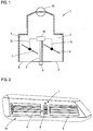
- Fig. 1 shows a ventilation device 1 for a motor vehicle with a first ventilation duct 2 and a first ventilation device opening 3, via which an air flow is guided into a motor vehicle interior.
- the ventilation device 1 has a second ventilation duct 4 and a second ventilation device opening 5, through which a further air flow is guided into the vehicle interior.
- the ventilation device 1 comprises a first closing device 6 and a second closing device 7, both of which are rotatably mounted, the first closing device 6 being configured to close the first ventilation duct 2 in its closed position by changing its degree of opening, and the second closing device 7 being configured to do so is to close the second ventilation duct 4 in its closed position by changing its degree of opening.
- an operating device 8 is arranged on the ventilation device 1, which has a first and a second degree of freedom A, B (see FIG Fig. 2 ).
- the operating device 8 is connected to a coupling device 10 via a mechanical movement coupling 9, the coupling device 10 in turn via a mechanical movement coupling 11 with the rotatably mounted first locking device 6 and via a mechanical one Movement coupling 12 is connected to the rotatably mounted second locking device 7, so that the coupling device 10 couples the first locking device 6 or the second locking device 7 with the operating device 8 as a function of an operation on the operating device 8.
- the mechanical movement coupling 9 is a rotatable shaft, the rotation of the shaft being able to be carried out by an operating action on the operating device 8 in accordance with the second degree of operating freedom B of the operating device 8.
- the coupling device 10 comprises two drive elements, one of which is coupled to the locking devices 6, 7.
- the position of the shaft can be adjusted such that the coupling device 10 connects the shaft either to the first of the drive elements and thus via the mechanical movement coupling 11 to the first locking device 6 or to the second of the drive elements and thus via the mechanical movement coupling 12 couples with the locking device 7.
- both locking devices 6, 7 can also be decoupled from the operating device 8, so that accidental actuation of the operating device 8 by a user or a vehicle occupant does not result in any adjustment of the locking devices 6, 7.
- Both the air flow guided through the first ventilation duct 2 and the air flow guided through the second ventilation duct 4 are generated by a central fan 13.
- Fig. 2 shows the already in Fig. 1 illustrated ventilation device 1 for a motor vehicle in a front view. Accordingly, the two ventilation device openings 3, 5 and the arrangement of the operating device 8 between the first ventilation device opening 3 and the second ventilation device opening 5 are shown.
- the operating device 8 can be adjusted according to its two operating degrees of freedom A, B, with the first operating degree of freedom A being able to select which of the closing devices 6, 7 is or are selected for the subsequent setting of the degree of opening by the second degree of operating freedom B and by means of the second degree of operating freedom B, the degree of opening of at least a selected one of the closing devices 6, 7 is adjustable.
- the operating device 8 is a rotary wheel which can be displaced according to the first degree of operating freedom A, whereby one of the locking devices 6, 7 can be selected.
- the operating wheel can be rotated in accordance with the second degree of operating freedom B, whereby the degree of opening of a closing device 6, 7 can be adjusted.
- the operating device in a middle position, which corresponds to a basic state of the operating device. From this basic state, the operating device can be adjusted according to the degrees of freedom A and B in the respective arrow direction in order to select at least one closing device 6, 7 for setting the opening degree, or respectively setting the opening degree of at least one selected one of the closing devices 6, 7.
- FIG. 2 The ventilation device 1 is shown in its installed state in a motor vehicle interior, the ventilation device 1 being embedded in a dashboard 14 of the motor vehicle and the operating device 8 thus being conveniently operated by both the driver and the front passenger.
- Fig. 3 shows a further embodiment of a ventilation device 15 with a first ventilation channel 16 and a first ventilation device opening 17 through which an air flow is guided into a motor vehicle interior.
- the ventilation device 15 comprises a second ventilation duct 18 and a second ventilation device opening 19, through which a further air flow is guided into the vehicle interior.
- a first closing device 20 in the form of a rotatably mounted flap is arranged in the first ventilation duct 16, so that the first ventilation duct 16 can be closed by the first closing device 20.
- a second closing device 21 also in the form of a arranged rotatably mounted flap, so that the second ventilation duct 18 can be closed by the second closing device 21.
- an operating device 22 is arranged, which has a sensor 23 for providing a sensor signal as a function of an operating input by a user.
- the sensor 23 is a sensor that detects the movements of a control wheel.
- the control wheel is rotatable on the one hand and adjustable in the transverse direction of the motor vehicle on the other hand.
- An operating action by a user in accordance with the first degree of operating freedom A can be carried out by adjusting the operating wheel in the axial direction or in the transverse direction of the motor vehicle.
- An operating action by a user in accordance with the second degree of operating freedom B can be carried out by rotating the operating wheel.
- the senor 23 could also be a touch-sensitive touch panel, with the aid of which a touch or a movement of a finger of a user in different directions can be detected.
- An operating action by a user in accordance with the first degree of operating freedom can be carried out by touching the touch panel with a finger and moving the finger in the transverse direction of the motor vehicle.
- An operating action by a user according to the second degree of operating freedom can be carried out by touching the touch panel with a finger and moving the finger in the vertical direction of the motor vehicle.
- a sensor signal generated by the sensor 23 as a function of the operating actions corresponding to the operating degrees of freedom is transmitted to a control device 31 and converted into a corresponding control signal by the control device 31. Then there is a wireless radio transmission of the control signal to the adjustment device 24.
- the adjustment device 24 comprises a first and a second actuator for adjusting the respective degree of opening of the first and second locking devices 20, 21. If a user performs an operating action corresponding to the first degree of freedom A of the operating wheel off, is through the Control device adapted as a function of the operator action which actuators of the adjustment device 24 are selected and this selection is stored.
- an opening degree signal is generated by the sensor 23 as a function of the rotation of the operating wheel.
- the opening degree signal is transmitted to the control device 31 and converted by this into opening degree control signals for the first and second actuators.
- the opening degree control signals are output only for those actuators that are assigned to the currently selected locking device or the currently selected locking devices.
- Both the air flow guided through the first ventilation duct 16 and the air flow guided through the second ventilation duct 18 are generated by a central fan 27.
- a lighting device 28 is arranged on the ventilation device 15 in such a way that two illuminants 29, 30 are located to the left and right of the operating device 22.
- a control device which is implemented together with the control device 31, controls the lighting device in such a way that, depending on which closing device 20, 21 is selected for adjusting the degree of opening, the corresponding illuminant 29, 30 emits visible light.
Landscapes
- Engineering & Computer Science (AREA)
- Mechanical Engineering (AREA)
- Physics & Mathematics (AREA)
- Thermal Sciences (AREA)
- Chemical & Material Sciences (AREA)
- Combustion & Propulsion (AREA)
- General Engineering & Computer Science (AREA)
- Air-Conditioning For Vehicles (AREA)
Claims (9)
- Dispositif de ventilation (1, 15) pour un véhicule automobile avec un premier canal de ventilation (2, 16) pour le guidage d'un premier flux d'air via une première ouverture de dispositif de ventilation (3, 17) dans un habitacle de véhicule automobile, un deuxième canal de ventilation (4, 18) pour le guidage d'un deuxième flux d'air via une deuxième ouverture de dispositif de ventilation (5, 19) dans l'habitacle de véhicule automobile, et un premier et un deuxième dispositif de fermeture (6, 20, 7, 21) dont le degré d'ouverture respectif est réglable par un dispositif de commande (8, 22) entre une position d'ouverture et une position de fermeture, dans lequel le premier dispositif de fermeture (6, 20) ferme dans la position de fermeture le premier canal de ventilation (2, 16) et le deuxième dispositif de fermeture (7, 21) ferme dans la position de fermeture le deuxième canal de ventilation (4, 18), dans lequel le dispositif de commande (8, 22) présente au moins deux degrés de liberté de commande (A, B), dans lequel il peut être sélectionné au moyen du premier degré de liberté de commande (A) lequel ou lesquels des dispositifs de fermeture (6, 20, 7, 21) est ou sont sélectionné(s) pour le réglage successif du degré d'ouverture par le deuxième degré de liberté de commande (B), et au moyen du deuxième degré de liberté de commande (B), le degré d'ouverture ou les degrés d'ouverture du dispositif de fermeture (6, 20, 7, 21) sélectionné est ou sont réglables,
caractérisé en ce
que le premier degré de liberté de commande (A) correspond à un mouvement linéaire ou à une rotation du dispositif de commande (8, 22) ou d'un composant du dispositif de commande (8, 22) dans une première direction de commande et le deuxième degré de liberté de commande (B) correspond à un mouvement linéaire ou à une rotation du dispositif de commande (8, 22) ou du composant dans une deuxième direction de commande coudée par rapport à la première direction de commande. - Dispositif de ventilation selon la revendication 1,
caractérisé en ce
que le dispositif de commande (8, 22) est agencé au niveau du dispositif de ventilation (1, 15) entre la première et la deuxième ouverture de dispositif de ventilation (3, 17, 5, 19). - Dispositif de ventilation selon la revendication 1 ou 2,
caractérisé en ce
qu'il présente un dispositif d'éclairage (28) et un dispositif de commande commandant le dispositif d'éclairage, dans lequel le dispositif de commande est aménagé pour commander le dispositif d'éclairage (28) en fonction du dispositif de fermeture (20, 21) sélectionné pour l'émission d'un signal optique. - Dispositif de ventilation selon l'une quelconque des revendications précédentes,
caractérisé en ce
qu'il présente un dispositif de couplage (10), qui couple en mouvement mécaniquement le dispositif de commande (8) avec le dispositif de fermeture (6, 7) sélectionné ou les dispositifs de fermeture (6, 7) sélectionnés. - Dispositif de ventilation selon l'une quelconque des revendications 1 à 3,
caractérisé en ce
qu'il comprend un dispositif de réglage (24), qui est aménagé pour le réglage séparé du degré d'ouverture du premier et du deuxième dispositif de fermeture en fonction d'un signal de commande, et un appareil de commande (31), qui est aménagé pour la mise à disposition du signal de commande en fonction d'une entrée de commande détectée par le biais d'au moins un capteur (23) du dispositif de commande (22). - Véhicule automobile,
caractérisé en ce
qu'il comprend au moins un dispositif de ventilation (1, 15) selon la revendication 1 ou selon l'une quelconque des revendications 3 à 5. - Véhicule automobile selon la revendication 6,
caractérisé en ce
qu'il présente un dispositif de commande, qui est réalisé pour la commande d'un dispositif d'affichage pour l'affichage d'une information décrivant le degré d'ouverture d'au moins un des dispositifs de fermeture (6, 20, 7, 21) et/ou la sélection d'un ou plusieurs des dispositifs de fermeture (6, 20, 7, 21). - Véhicule automobile selon la revendication 6 ou 7,
caractérisé en ce
que le dispositif de commande (8, 22) est agencé entre les premières et les deuxièmes ouvertures de dispositif de ventilation (3, 17, 5, 19) soit au niveau du dispositif de ventilation (1, 15) soit au niveau d'un composant de l'habitacle de véhicule. - Véhicule automobile selon l'une quelconque des revendications 6 à 8,
caractérisé en ce
que le premier degré de liberté de commande (A) correspond à un mouvement du dispositif de commande, ou à un composant du dispositif de commande dans la direction transversale du véhicule automobile.
Applications Claiming Priority (2)
| Application Number | Priority Date | Filing Date | Title |
|---|---|---|---|
| DE102016004992.8A DE102016004992B3 (de) | 2016-04-25 | 2016-04-25 | Lüftungseinrichtung für ein Kraftfahrzeug und zugehöriges Kraftfahrzeug |
| PCT/EP2017/000206 WO2017186321A1 (fr) | 2016-04-25 | 2017-02-14 | Dispositif de ventilation pour véhicule à moteur et véhicule automobile associé |
Publications (2)
| Publication Number | Publication Date |
|---|---|
| EP3448700A1 EP3448700A1 (fr) | 2019-03-06 |
| EP3448700B1 true EP3448700B1 (fr) | 2020-10-07 |
Family
ID=58046617
Family Applications (1)
| Application Number | Title | Priority Date | Filing Date |
|---|---|---|---|
| EP17705311.3A Active EP3448700B1 (fr) | 2016-04-25 | 2017-02-14 | Dispositif d'aération pour un véhicule et véhicule comprenant un tel dispositif |
Country Status (4)
| Country | Link |
|---|---|
| EP (1) | EP3448700B1 (fr) |
| CN (1) | CN109070689B (fr) |
| DE (1) | DE102016004992B3 (fr) |
| WO (1) | WO2017186321A1 (fr) |
Families Citing this family (2)
| Publication number | Priority date | Publication date | Assignee | Title |
|---|---|---|---|---|
| CN110978961A (zh) * | 2019-12-03 | 2020-04-10 | 常熟市汽车饰件股份有限公司 | 后置双摆车辆出风口调节结构 |
| CN116587813A (zh) * | 2022-07-01 | 2023-08-15 | 北京车和家汽车科技有限公司 | 可变风道系统及车辆 |
Family Cites Families (8)
| Publication number | Priority date | Publication date | Assignee | Title |
|---|---|---|---|---|
| DE4327266C1 (de) * | 1993-08-13 | 1994-08-25 | Daimler Benz Ag | Luftdüse |
| DE102011114766B4 (de) * | 2011-10-01 | 2014-09-04 | Audi Ag | Lüftungs- und Heizungsmodul für Kraftfahrzeuge mit wenigstens einem Luftführungskanal |
| DE102013008066B4 (de) * | 2013-05-10 | 2026-03-19 | Volkswagen Aktiengesellschaft | Belüftungseinrichtung |
| KR101409532B1 (ko) * | 2013-06-05 | 2014-06-19 | 주식회사 니프코코리아 | 자동차 에어벤트의 듀얼 댐퍼 장치 |
| CN104015588B (zh) * | 2014-06-11 | 2016-06-08 | 安徽江淮汽车股份有限公司 | 一种带除霜与吹面的多功能出风口总成 |
| DE102014221133A1 (de) * | 2014-10-17 | 2016-04-21 | Volkswagen Aktiengesellschaft | Bedieneinrichtung in einem Kraftfahrzeug |
| DE102015004062A1 (de) * | 2015-03-28 | 2015-08-27 | Daimler Ag | Luftzufuhreinrichtung für eine Klimatisierungsvorrichtung in einem Kraftfahrzeug |
| DE202015106878U1 (de) * | 2015-12-17 | 2016-01-15 | Ford Global Technologies, Llc | Luftausströmer für Heizungs- und Belüftungs- oder Klimaanlagen von Kraftfahrzeugen |
-
2016
- 2016-04-25 DE DE102016004992.8A patent/DE102016004992B3/de not_active Expired - Fee Related
-
2017
- 2017-02-14 CN CN201780025565.7A patent/CN109070689B/zh active Active
- 2017-02-14 WO PCT/EP2017/000206 patent/WO2017186321A1/fr not_active Ceased
- 2017-02-14 EP EP17705311.3A patent/EP3448700B1/fr active Active
Non-Patent Citations (1)
| Title |
|---|
| None * |
Also Published As
| Publication number | Publication date |
|---|---|
| DE102016004992B3 (de) | 2017-05-11 |
| WO2017186321A1 (fr) | 2017-11-02 |
| CN109070689B (zh) | 2022-09-06 |
| EP3448700A1 (fr) | 2019-03-06 |
| CN109070689A (zh) | 2018-12-21 |
Similar Documents
| Publication | Publication Date | Title |
|---|---|---|
| EP1809928B1 (fr) | Dispositif d'actionnement a commutateur rotatif | |
| EP0888916B1 (fr) | Système avec lamelles pour dispositifs d'aération pour régler la ventilation, notamment pour l'aération de véhicules à moteur | |
| EP2552726B1 (fr) | Dispositif pour la commande de diverses fonctions d'un véhicule à moteur | |
| DE102014203511B3 (de) | Luftausströmer für ein Fahrzeug | |
| DE102014105273B3 (de) | Einrichtung zum Verstellen von Lamellen eines Luftausströmers | |
| EP2670615B1 (fr) | Système servant à commander plusieurs fonctions différentes d'un véhicule automobile | |
| DE102016220671B4 (de) | Luftausströmer für Heizungs- und Belüftungs- oder Klimaanlagen von Kraftfahrzeugen | |
| EP1520738B1 (fr) | Aerateur à lamelles, en particulier pour climatisation de véhicule | |
| EP3381725B1 (fr) | Aérateur | |
| DE102015218309B4 (de) | Belüftungsdüse zur Belüftung eines Fahrzeuginnenraums | |
| DE102016013353A1 (de) | Ausströmer für ein Kraftfahrzeug und zugehöriges Kraftfahrzeug | |
| DE102011106784A1 (de) | Bedieneinheit für eine Funktionseinrichtung und Fahrzeug mit einer solchen Bedieneinheit, insbesondere zum Bedienen einer Klimatisierungsanlage | |
| WO2020234031A1 (fr) | Unité de sortie d'air pour l'aération d'un véhicule et véhicule | |
| DE102021111535A1 (de) | Luftausströmeranordnung | |
| DE102019132921B4 (de) | Luftausströmer mit Bedieneinrichtung | |
| DE102016004992B3 (de) | Lüftungseinrichtung für ein Kraftfahrzeug und zugehöriges Kraftfahrzeug | |
| DE202005012570U1 (de) | Luftdüse | |
| WO2020160960A1 (fr) | Dispositif de commande pour un élément de guidage d'air monté monté pivotant | |
| DE202015106878U1 (de) | Luftausströmer für Heizungs- und Belüftungs- oder Klimaanlagen von Kraftfahrzeugen | |
| EP3478534B1 (fr) | Procede et dispositif de commande de la climatisation d'un siege de vehicule | |
| DE102019121738A1 (de) | Bedieneinrichtung für ein verschwenkbar gelagertes Luftleitelement und Luftausströmer mit Bedieneinrichtung | |
| DE102014221133A1 (de) | Bedieneinrichtung in einem Kraftfahrzeug | |
| DE102010031085A1 (de) | Luftausströmer | |
| EP3553626B1 (fr) | Dispositif de commande | |
| DE19750160A1 (de) | Innenluft/Außenluft-Schaltvorrichtung mit Staudruck-Regeleinheit für eine Klimaanlage für ein Fahrzeug |
Legal Events
| Date | Code | Title | Description |
|---|---|---|---|
| STAA | Information on the status of an ep patent application or granted ep patent |
Free format text: STATUS: UNKNOWN |
|
| STAA | Information on the status of an ep patent application or granted ep patent |
Free format text: STATUS: THE INTERNATIONAL PUBLICATION HAS BEEN MADE |
|
| PUAI | Public reference made under article 153(3) epc to a published international application that has entered the european phase |
Free format text: ORIGINAL CODE: 0009012 |
|
| STAA | Information on the status of an ep patent application or granted ep patent |
Free format text: STATUS: REQUEST FOR EXAMINATION WAS MADE |
|
| 17P | Request for examination filed |
Effective date: 20181126 |
|
| AK | Designated contracting states |
Kind code of ref document: A1 Designated state(s): AL AT BE BG CH CY CZ DE DK EE ES FI FR GB GR HR HU IE IS IT LI LT LU LV MC MK MT NL NO PL PT RO RS SE SI SK SM TR |
|
| AX | Request for extension of the european patent |
Extension state: BA ME |
|
| DAV | Request for validation of the european patent (deleted) | ||
| DAX | Request for extension of the european patent (deleted) | ||
| STAA | Information on the status of an ep patent application or granted ep patent |
Free format text: STATUS: EXAMINATION IS IN PROGRESS |
|
| 17Q | First examination report despatched |
Effective date: 20191122 |
|
| GRAP | Despatch of communication of intention to grant a patent |
Free format text: ORIGINAL CODE: EPIDOSNIGR1 |
|
| STAA | Information on the status of an ep patent application or granted ep patent |
Free format text: STATUS: GRANT OF PATENT IS INTENDED |
|
| INTG | Intention to grant announced |
Effective date: 20200728 |
|
| GRAS | Grant fee paid |
Free format text: ORIGINAL CODE: EPIDOSNIGR3 |
|
| GRAA | (expected) grant |
Free format text: ORIGINAL CODE: 0009210 |
|
| STAA | Information on the status of an ep patent application or granted ep patent |
Free format text: STATUS: THE PATENT HAS BEEN GRANTED |
|
| AK | Designated contracting states |
Kind code of ref document: B1 Designated state(s): AL AT BE BG CH CY CZ DE DK EE ES FI FR GB GR HR HU IE IS IT LI LT LU LV MC MK MT NL NO PL PT RO RS SE SI SK SM TR |
|
| REG | Reference to a national code |
Ref country code: GB Ref legal event code: FG4D Free format text: NOT ENGLISH |
|
| REG | Reference to a national code |
Ref country code: AT Ref legal event code: REF Ref document number: 1320803 Country of ref document: AT Kind code of ref document: T Effective date: 20201015 Ref country code: CH Ref legal event code: EP |
|
| REG | Reference to a national code |
Ref country code: IE Ref legal event code: FG4D Free format text: LANGUAGE OF EP DOCUMENT: GERMAN |
|
| REG | Reference to a national code |
Ref country code: DE Ref legal event code: R096 Ref document number: 502017007603 Country of ref document: DE |
|
| REG | Reference to a national code |
Ref country code: NL Ref legal event code: MP Effective date: 20201007 |
|
| PG25 | Lapsed in a contracting state [announced via postgrant information from national office to epo] |
Ref country code: NO Free format text: LAPSE BECAUSE OF FAILURE TO SUBMIT A TRANSLATION OF THE DESCRIPTION OR TO PAY THE FEE WITHIN THE PRESCRIBED TIME-LIMIT Effective date: 20210107 Ref country code: PT Free format text: LAPSE BECAUSE OF FAILURE TO SUBMIT A TRANSLATION OF THE DESCRIPTION OR TO PAY THE FEE WITHIN THE PRESCRIBED TIME-LIMIT Effective date: 20210208 Ref country code: RS Free format text: LAPSE BECAUSE OF FAILURE TO SUBMIT A TRANSLATION OF THE DESCRIPTION OR TO PAY THE FEE WITHIN THE PRESCRIBED TIME-LIMIT Effective date: 20201007 Ref country code: FI Free format text: LAPSE BECAUSE OF FAILURE TO SUBMIT A TRANSLATION OF THE DESCRIPTION OR TO PAY THE FEE WITHIN THE PRESCRIBED TIME-LIMIT Effective date: 20201007 Ref country code: GR Free format text: LAPSE BECAUSE OF FAILURE TO SUBMIT A TRANSLATION OF THE DESCRIPTION OR TO PAY THE FEE WITHIN THE PRESCRIBED TIME-LIMIT Effective date: 20210108 |
|
| REG | Reference to a national code |
Ref country code: LT Ref legal event code: MG4D |
|
| PG25 | Lapsed in a contracting state [announced via postgrant information from national office to epo] |
Ref country code: ES Free format text: LAPSE BECAUSE OF FAILURE TO SUBMIT A TRANSLATION OF THE DESCRIPTION OR TO PAY THE FEE WITHIN THE PRESCRIBED TIME-LIMIT Effective date: 20201007 Ref country code: BG Free format text: LAPSE BECAUSE OF FAILURE TO SUBMIT A TRANSLATION OF THE DESCRIPTION OR TO PAY THE FEE WITHIN THE PRESCRIBED TIME-LIMIT Effective date: 20210107 Ref country code: IS Free format text: LAPSE BECAUSE OF FAILURE TO SUBMIT A TRANSLATION OF THE DESCRIPTION OR TO PAY THE FEE WITHIN THE PRESCRIBED TIME-LIMIT Effective date: 20210207 Ref country code: PL Free format text: LAPSE BECAUSE OF FAILURE TO SUBMIT A TRANSLATION OF THE DESCRIPTION OR TO PAY THE FEE WITHIN THE PRESCRIBED TIME-LIMIT Effective date: 20201007 Ref country code: LV Free format text: LAPSE BECAUSE OF FAILURE TO SUBMIT A TRANSLATION OF THE DESCRIPTION OR TO PAY THE FEE WITHIN THE PRESCRIBED TIME-LIMIT Effective date: 20201007 Ref country code: SE Free format text: LAPSE BECAUSE OF FAILURE TO SUBMIT A TRANSLATION OF THE DESCRIPTION OR TO PAY THE FEE WITHIN THE PRESCRIBED TIME-LIMIT Effective date: 20201007 |
|
| PG25 | Lapsed in a contracting state [announced via postgrant information from national office to epo] |
Ref country code: NL Free format text: LAPSE BECAUSE OF FAILURE TO SUBMIT A TRANSLATION OF THE DESCRIPTION OR TO PAY THE FEE WITHIN THE PRESCRIBED TIME-LIMIT Effective date: 20201007 Ref country code: HR Free format text: LAPSE BECAUSE OF FAILURE TO SUBMIT A TRANSLATION OF THE DESCRIPTION OR TO PAY THE FEE WITHIN THE PRESCRIBED TIME-LIMIT Effective date: 20201007 |
|
| REG | Reference to a national code |
Ref country code: DE Ref legal event code: R097 Ref document number: 502017007603 Country of ref document: DE |
|
| PG25 | Lapsed in a contracting state [announced via postgrant information from national office to epo] |
Ref country code: RO Free format text: LAPSE BECAUSE OF FAILURE TO SUBMIT A TRANSLATION OF THE DESCRIPTION OR TO PAY THE FEE WITHIN THE PRESCRIBED TIME-LIMIT Effective date: 20201007 Ref country code: SK Free format text: LAPSE BECAUSE OF FAILURE TO SUBMIT A TRANSLATION OF THE DESCRIPTION OR TO PAY THE FEE WITHIN THE PRESCRIBED TIME-LIMIT Effective date: 20201007 Ref country code: SM Free format text: LAPSE BECAUSE OF FAILURE TO SUBMIT A TRANSLATION OF THE DESCRIPTION OR TO PAY THE FEE WITHIN THE PRESCRIBED TIME-LIMIT Effective date: 20201007 Ref country code: EE Free format text: LAPSE BECAUSE OF FAILURE TO SUBMIT A TRANSLATION OF THE DESCRIPTION OR TO PAY THE FEE WITHIN THE PRESCRIBED TIME-LIMIT Effective date: 20201007 Ref country code: CZ Free format text: LAPSE BECAUSE OF FAILURE TO SUBMIT A TRANSLATION OF THE DESCRIPTION OR TO PAY THE FEE WITHIN THE PRESCRIBED TIME-LIMIT Effective date: 20201007 Ref country code: LT Free format text: LAPSE BECAUSE OF FAILURE TO SUBMIT A TRANSLATION OF THE DESCRIPTION OR TO PAY THE FEE WITHIN THE PRESCRIBED TIME-LIMIT Effective date: 20201007 |
|
| PLBE | No opposition filed within time limit |
Free format text: ORIGINAL CODE: 0009261 |
|
| STAA | Information on the status of an ep patent application or granted ep patent |
Free format text: STATUS: NO OPPOSITION FILED WITHIN TIME LIMIT |
|
| PG25 | Lapsed in a contracting state [announced via postgrant information from national office to epo] |
Ref country code: DK Free format text: LAPSE BECAUSE OF FAILURE TO SUBMIT A TRANSLATION OF THE DESCRIPTION OR TO PAY THE FEE WITHIN THE PRESCRIBED TIME-LIMIT Effective date: 20201007 |
|
| 26N | No opposition filed |
Effective date: 20210708 |
|
| PG25 | Lapsed in a contracting state [announced via postgrant information from national office to epo] |
Ref country code: MC Free format text: LAPSE BECAUSE OF FAILURE TO SUBMIT A TRANSLATION OF THE DESCRIPTION OR TO PAY THE FEE WITHIN THE PRESCRIBED TIME-LIMIT Effective date: 20201007 |
|
| REG | Reference to a national code |
Ref country code: BE Ref legal event code: MM Effective date: 20210228 |
|
| PG25 | Lapsed in a contracting state [announced via postgrant information from national office to epo] |
Ref country code: CH Free format text: LAPSE BECAUSE OF NON-PAYMENT OF DUE FEES Effective date: 20210228 Ref country code: AL Free format text: LAPSE BECAUSE OF FAILURE TO SUBMIT A TRANSLATION OF THE DESCRIPTION OR TO PAY THE FEE WITHIN THE PRESCRIBED TIME-LIMIT Effective date: 20201007 Ref country code: IT Free format text: LAPSE BECAUSE OF FAILURE TO SUBMIT A TRANSLATION OF THE DESCRIPTION OR TO PAY THE FEE WITHIN THE PRESCRIBED TIME-LIMIT Effective date: 20201007 Ref country code: LU Free format text: LAPSE BECAUSE OF NON-PAYMENT OF DUE FEES Effective date: 20210214 Ref country code: LI Free format text: LAPSE BECAUSE OF NON-PAYMENT OF DUE FEES Effective date: 20210228 |
|
| PG25 | Lapsed in a contracting state [announced via postgrant information from national office to epo] |
Ref country code: SI Free format text: LAPSE BECAUSE OF FAILURE TO SUBMIT A TRANSLATION OF THE DESCRIPTION OR TO PAY THE FEE WITHIN THE PRESCRIBED TIME-LIMIT Effective date: 20201007 |
|
| PG25 | Lapsed in a contracting state [announced via postgrant information from national office to epo] |
Ref country code: IE Free format text: LAPSE BECAUSE OF NON-PAYMENT OF DUE FEES Effective date: 20210214 |
|
| PG25 | Lapsed in a contracting state [announced via postgrant information from national office to epo] |
Ref country code: IS Free format text: LAPSE BECAUSE OF FAILURE TO SUBMIT A TRANSLATION OF THE DESCRIPTION OR TO PAY THE FEE WITHIN THE PRESCRIBED TIME-LIMIT Effective date: 20210207 |
|
| PG25 | Lapsed in a contracting state [announced via postgrant information from national office to epo] |
Ref country code: BE Free format text: LAPSE BECAUSE OF NON-PAYMENT OF DUE FEES Effective date: 20210228 |
|
| REG | Reference to a national code |
Ref country code: AT Ref legal event code: MM01 Ref document number: 1320803 Country of ref document: AT Kind code of ref document: T Effective date: 20220214 |
|
| PG25 | Lapsed in a contracting state [announced via postgrant information from national office to epo] |
Ref country code: AT Free format text: LAPSE BECAUSE OF NON-PAYMENT OF DUE FEES Effective date: 20220214 |
|
| PG25 | Lapsed in a contracting state [announced via postgrant information from national office to epo] |
Ref country code: CY Free format text: LAPSE BECAUSE OF FAILURE TO SUBMIT A TRANSLATION OF THE DESCRIPTION OR TO PAY THE FEE WITHIN THE PRESCRIBED TIME-LIMIT Effective date: 20201007 |
|
| P01 | Opt-out of the competence of the unified patent court (upc) registered |
Effective date: 20230530 |
|
| PG25 | Lapsed in a contracting state [announced via postgrant information from national office to epo] |
Ref country code: HU Free format text: LAPSE BECAUSE OF FAILURE TO SUBMIT A TRANSLATION OF THE DESCRIPTION OR TO PAY THE FEE WITHIN THE PRESCRIBED TIME-LIMIT; INVALID AB INITIO Effective date: 20170214 |
|
| PG25 | Lapsed in a contracting state [announced via postgrant information from national office to epo] |
Ref country code: MK Free format text: LAPSE BECAUSE OF FAILURE TO SUBMIT A TRANSLATION OF THE DESCRIPTION OR TO PAY THE FEE WITHIN THE PRESCRIBED TIME-LIMIT Effective date: 20201007 |
|
| PG25 | Lapsed in a contracting state [announced via postgrant information from national office to epo] |
Ref country code: TR Free format text: LAPSE BECAUSE OF FAILURE TO SUBMIT A TRANSLATION OF THE DESCRIPTION OR TO PAY THE FEE WITHIN THE PRESCRIBED TIME-LIMIT Effective date: 20201007 |
|
| PG25 | Lapsed in a contracting state [announced via postgrant information from national office to epo] |
Ref country code: MT Free format text: LAPSE BECAUSE OF FAILURE TO SUBMIT A TRANSLATION OF THE DESCRIPTION OR TO PAY THE FEE WITHIN THE PRESCRIBED TIME-LIMIT Effective date: 20201007 |
|
| PGFP | Annual fee paid to national office [announced via postgrant information from national office to epo] |
Ref country code: DE Payment date: 20250228 Year of fee payment: 9 |
|
| PGFP | Annual fee paid to national office [announced via postgrant information from national office to epo] |
Ref country code: FR Payment date: 20250218 Year of fee payment: 9 |
|
| PGFP | Annual fee paid to national office [announced via postgrant information from national office to epo] |
Ref country code: GB Payment date: 20250221 Year of fee payment: 9 |