EP3449128B1 - Pompe à cavité progressive - Google Patents
Pompe à cavité progressive Download PDFInfo
- Publication number
- EP3449128B1 EP3449128B1 EP17717685.6A EP17717685A EP3449128B1 EP 3449128 B1 EP3449128 B1 EP 3449128B1 EP 17717685 A EP17717685 A EP 17717685A EP 3449128 B1 EP3449128 B1 EP 3449128B1
- Authority
- EP
- European Patent Office
- Prior art keywords
- pump
- eccentric screw
- drive wheel
- screw pump
- rotor
- Prior art date
- Legal status (The legal status is an assumption and is not a legal conclusion. Google has not performed a legal analysis and makes no representation as to the accuracy of the status listed.)
- Active
Links
Images



Classifications
-
- F—MECHANICAL ENGINEERING; LIGHTING; HEATING; WEAPONS; BLASTING
- F04—POSITIVE - DISPLACEMENT MACHINES FOR LIQUIDS; PUMPS FOR LIQUIDS OR ELASTIC FLUIDS
- F04C—ROTARY-PISTON, OR OSCILLATING-PISTON, POSITIVE-DISPLACEMENT MACHINES FOR LIQUIDS; ROTARY-PISTON, OR OSCILLATING-PISTON, POSITIVE-DISPLACEMENT PUMPS
- F04C2/00—Rotary-piston machines or pumps
- F04C2/08—Rotary-piston machines or pumps of intermeshing-engagement type, i.e. with engagement of co-operating members similar to that of toothed gearing
- F04C2/10—Rotary-piston machines or pumps of intermeshing-engagement type, i.e. with engagement of co-operating members similar to that of toothed gearing of internal-axis type with the outer member having more teeth or tooth-equivalents, e.g. rollers, than the inner member
- F04C2/107—Rotary-piston machines or pumps of intermeshing-engagement type, i.e. with engagement of co-operating members similar to that of toothed gearing of internal-axis type with the outer member having more teeth or tooth-equivalents, e.g. rollers, than the inner member with helical teeth
- F04C2/1071—Rotary-piston machines or pumps of intermeshing-engagement type, i.e. with engagement of co-operating members similar to that of toothed gearing of internal-axis type with the outer member having more teeth or tooth-equivalents, e.g. rollers, than the inner member with helical teeth the inner and outer member having a different number of threads and one of the two being made of elastic materials, e.g. Moineau type
- F04C2/1073—Rotary-piston machines or pumps of intermeshing-engagement type, i.e. with engagement of co-operating members similar to that of toothed gearing of internal-axis type with the outer member having more teeth or tooth-equivalents, e.g. rollers, than the inner member with helical teeth the inner and outer member having a different number of threads and one of the two being made of elastic materials, e.g. Moineau type where one member is stationary while the other member rotates and orbits
-
- F—MECHANICAL ENGINEERING; LIGHTING; HEATING; WEAPONS; BLASTING
- F04—POSITIVE - DISPLACEMENT MACHINES FOR LIQUIDS; PUMPS FOR LIQUIDS OR ELASTIC FLUIDS
- F04C—ROTARY-PISTON, OR OSCILLATING-PISTON, POSITIVE-DISPLACEMENT MACHINES FOR LIQUIDS; ROTARY-PISTON, OR OSCILLATING-PISTON, POSITIVE-DISPLACEMENT PUMPS
- F04C15/00—Component parts, details or accessories of machines, pumps or pumping installations, not provided for in groups F04C2/00 - F04C14/00
- F04C15/0057—Driving elements, brakes, couplings, transmission specially adapted for machines or pumps
- F04C15/0061—Means for transmitting movement from the prime mover to driven parts of the pump, e.g. clutches, couplings, transmissions
- F04C15/0065—Means for transmitting movement from the prime mover to driven parts of the pump, e.g. clutches, couplings, transmissions for eccentric movement
Definitions
- the present invention relates to an eccentric screw pump, in particular an eccentric screw pump for a metering system for a domestic appliance, for example a washing machine.
- metering pumps for fluids, in particular for liquid detergents, are of interest in order to be used as part of a metering system in domestic appliances.
- metering systems with metering pumps in different variants are known, such as volume pumps in the form of gear pumps, hose pumps, or piston pumps.
- the disclosure document GB 2 120 729 A describes a screw pump.
- EP 0 003 676 A1 shows an inner-axis machine with a helical profile on the rotor and in the stator.
- eccentric screw pumps are also known. From the pamphlet DE 10212184A1 it is known, for example, to use an eccentric screw pump in a commercial washing machine in order to supply a paste-like detergent concentrate from a container of the commercial washing machine.
- an eccentric screw pump in principle only has a single moving part, it is relatively inexpensive and robust and should therefore in principle be well suited for use in household appliances, in particular as a metering pump.
- the simplicity of an eccentric screw pump requires a relatively complicated drive, since a two-dimensional movement of the rotor of the eccentric screw pump must be implemented, which consists of a superimposition of a self-rotation of the rotor and a counter-rotation of the rotor axis on a cylinder jacket with the same frequency.
- Drives of known eccentric screw pumps are hardly suitable for being used as part of a metering pump in a household appliance, in particular a washing machine, because of their complexity and the associated costs.
- the present invention is based on the object of providing an eccentric screw pump with a simply constructed and inexpensive drive system,
- the eccentric screw pump - apart from the drive system - has only a single moving part for conveying a fluid and the drive system is suitable for realizing the two-dimensional movement of a rotor of the eccentric screw pump.
- the object is achieved by means of an eccentric screw pump according to claim 1.
- the eccentric screw pump is designed as a 2: 1 hypocycloid eccentric screw pump, the 2: 1 hypocycloid being defined by a first circle with a radius R, which rolls off slip-free on the inside of a second circle with a radius 2R.
- the pump rotor is attached eccentrically to the drive wheel in such a way that the longitudinal axis of the pump rotor runs at a distance R from the center point of the drive wheel.
- the drive wheel is a gear and the eccentric screw pump further comprises a drive screw which is designed to drive the drive wheel.
- the drive wheel has a circular circumference.
- the drive wheel is a crown wheel with teeth or cylindrical pins.
- the drive wheel is a bevel gear.
- the drive wheel comprises a groove-like toothing.
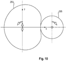
- the drive wheel has a kidney-shaped circumference and the eccentric screw pump further comprises a motor-side drive wheel which is designed to drive the drive wheel.
- the pump rotor and the pump stator have a respective shape which defines a periodicity along the longitudinal axis of the pump rotor, the length of the pump rotor and the pump stator corresponding to at least one period along the longitudinal axis of the pump stator.
- a domestic appliance in particular a washing machine, with an eccentric screw pump according to the first aspect of the invention is provided.
- Figure 1 illustrates the kinematics of a rotor 107 relative to a stator 109, as it is in an eccentric screw pump 100 according to a detailed below, in particular in connection with the Figures 6 to 9 described embodiment of the invention is realized, which is a 2: 1 hypocycloid eccentric screw pump 100.
- the movement of the rotor 107 can be described by means of a first circle 10 with a radius R, which is in a second circle 20, which is twice as large as the first circle 10 (i.e. with a radius 2R; hence the Ratio 2: 1), unrolls without slippage.
- the eccentricity of the movement of the rotor 107 corresponds to the radius R of the first rolling circle 10.
- the center of the rolling first circle 10, ie the center of the rotor 107 (or in the plan view of FIG Figures 1 to 3 the point of penetration of the longitudinal axis of the rotor 107) describes a further circle during its movement, which is concentric with the second circle 20 and from which in Figure 1 a section is indicated by the curved arrow.
- the diameter of the further circle described by the first circle 10 corresponds, as it were, to the "piston stroke" of the eccentric screw pump 100, as will be seen below in connection with FIG Figure 5 continues.
- the illustrated kinematics of the eccentric screw pump 100 can be implemented by means of a kinematic model that is shown in Figure 2 is shown.
- This kinematic model consists of a coupling 101 which has a fixed length 2R and at the two ends of which a sliding element 102a, 102b is articulated to the coupling 101.
- the first sliding element 102a is guided along the y-axis and the second sliding element 102b is guided along the orthogonal x-axis of a Cartesian coordinate system.
- the coupling 101 corresponds to the diameter of the first circle 10 of Figure 1 , so has a length of 2R.
- the center of the coupling 101 executes a circular movement with the radius R around the origin of the coordinate system which coincides with the center of the second circle 20.
- the first and the second sliding element 102a, 102b each perform a linear oscillation with the amplitude 2R along the y-axis and the x-axis, the oscillation of the first sliding element 102a being 90 ° out of phase the oscillation of the second slide member 102b takes place.
- the eccentric screw pump 100 is designed such that the center point of the coupling 101 of the kinematic model of Figure 2 coincides with the longitudinal axis of the rotor 107 (more precisely with the point of penetration of the longitudinal axis) of the eccentric screw pump 100.
- Figure 5 which shows a cross-sectional view of the pump stator 109 and the pump rotor 107 of the eccentric screw pump 100 according to such an embodiment, there is a circular rotor cross-section in a slot-shaped stator cross-section in each cross-section perpendicular to the longitudinal axis of the pump rotor 107.
- Figure 5 a cross-sectional view at a height along the longitudinal axis of the rotor 107, which corresponds to a guidance of the rotor 107 by the stator 109 in the x-direction analogous to the guidance of the second sliding element 102b of FIG Figure 2 is equivalent to.
- a guide of the rotor 107 is defined by the stator 109 in a respective direction which, for example, is orthogonal to the guide of Figure 5 runs, ie a guide in the y-direction analogous to the guide of the first sliding element 102a of FIG Figure 1 , or at a different angle to it.
- the point P1 is the center point of the pump stator 109.
- Each cross section of the stator 109 has the point P1 as the center of symmetry.
- the point P3 is located at a distance 2R from the center point of the stator 109, that is to say from the point P1, in the illustrated phase, that is to say at the illustrated height, on the x-axis.
- this point P3 on the rotor 107 performs an oscillation along the x-axis with the amplitude 2R, ie a "piston stroke" totaling 4R for the cross section shown here by way of example.
- the point P3 corresponds to the center of the circle of the rotor cross-section.
- the center of the circle of the drive wheel 103 ie the center of the circle, is located at this point P3 Drive wheel axle runs through this point.
- the drive wheel 103 executes a movement oscillating in the x direction in the reference system of the stator 109.
- the rotor axis runs through the point P2, which is at a distance R from the stator center point P1.
- this point P2 moves in the reference system of the stator 109 on a circle with radius R around the stator center point P1.
- the point P2 moves on a circle with radius R around the center of the circle of the rotor cross-section, that is to say around the point P3.
- the pin described may be attached to the drive wheel 103, which serves to generate an axial force on the rotor 107. With such an attachment, the pin executes a circular movement in the reference system of the stator 109 (in Figure 7 the circle of movement of the pivot center point is shown).
- points P1, P2 and P3 correspond to in Figure 2 , which, however, corresponds to a different orientation of the rotor 107 (namely an orientation with an angle ⁇ of approximately 60 °), the center of the large circle 20 (P1), ie the stator center, the center of the coupling 101 (P2), ie the im Reference system of the stator 109 on a circle with radius R around the stator center point revolving rotor axis, and the articulation point of the second sliding element 102b (P3), ie the center point of the rotor cross section oscillating along the x-axis.
- embodiments of the invention according to the invention include a drive mechanism which is the same as that shown in FIG Figure 1 and the kinematic model of Figure 2
- the illustrated movement of the rotor 107 is generated or transmitted to the rotor 107 by means of a centric rotation.
- Figure 3 illustrates an implementation of the kinematic model of FIG Figure 2 as part of a drive mechanism of the eccentric screw pump 100 according to one embodiment.
- the drive mechanism comprises a round drive wheel in the form of a gear 103 and a cylindrical drive worm 105 which is designed to interact in a known manner with the teeth of the gear 103 (including the exemplary tooth 103a) in such a way that a Drive motor The rotational movement of the drive worm 105 caused results in a rotation of the gear 103.
- a centric attachment of the round gear 103 leads to the point in the kinematic model of Figure 2 corresponds to the position of the first sliding element 102a (ie the center of the gear wheel 103 is located at the pivot point of the first sliding element 102a), in addition to the fact that the gear wheel 103 simultaneously executes an oscillation in the y-direction with an amplitude of 2R when it rotates about its center, there is no movement of the gear wheel 103 in the x direction.
- the person skilled in the art will recognize that the length of the coupling 101 in relation to the radius of the drive wheel 103 in embodiments of the invention can be significantly smaller than in FIG Figure 3 shown.
- Figure 3 also shows a distance m between the longitudinal axis of the drive worm 105, which has a half diameter d / 2.
- the drive wheel 103 is thus fixed centrally at the point that is shown in the kinematic model of FIG Figure 2 corresponds to the position of the first sliding element 102a, and the pump rotor 107 is connected to the drive wheel 103 in such a way that the coupling 101 coincides with the diameter of the pump rotor 107 or the center point of the coupling 101 coincides with the longitudinal axis of the pump rotor 107.
- the pump rotor is eccentrically attached to the drive wheel 103 at a distance R from the center thereof.
- the cylindrical drive worm 105 which is arranged parallel to the y-axis at a suitable distance m, can, as in a conventional worm drive, achieve a self-rotation of the gear 103 by rotating around its axis, while at the same time the gear 103 moves along the drive worm 105 moved back and forth in an oscillation with amplitude 2R.
- Figure 4 4 shows the relative positions of the drive wheel 103 to the drive screw 105 of the eccentric screw pump 100 according to one embodiment with a full revolution of the drive wheel 103.
- the coupling and the sliding elements in the views of Figure 4 are not actually present in the eccentric screw pump 100, but merely serve to illustrate that the kinematic model of Figure 2 is realized.
- the movement of the pump rotor 107 of the eccentric screw pump 100 can be thought of as the movement of the circle, the diameter of which is defined by the coupling, as already described above.
- the different views of Figure 4 illustrate once again that with a full revolution of the drive wheel 103 its center moves back and forth with an oscillating only in the y-direction, i.e. the vertical direction, but no movement in the x-direction, that is, the horizontal direction, i.e. in particular the distance between the center of the drive wheel 103 and the longitudinal axis of the drive worm 105 does not change.
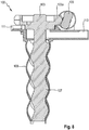
- the Figures 6 to 9 show different views of an embodiment of the eccentric pump worm 100, namely a perspective view, a top view, a longitudinal section and a perspective sectional view.
- the drive wheel 103 is designed as a spur gear 103 with helical teeth, for example the tooth 103a, which can be driven by the drive screw 105 designed as a cylindrical screw.
- the eccentric attachment of the pump rotor 107 to the drive wheel 103 can be seen, for example, from the top view of FIG Figure 7 remove. It should be noted here that the center point of the pin protruding upwards on the gearwheel 103 is not the fulcrum around which the gearwheel 103 rotates (eccentrically), since, as already described above in connection with Figure 5 described, the pin executes a circular motion while the gear 103 rotates about its geometric center.
- the pin can serve to press the pump rotor 107 axially into the pump stator 109 by means of a pressure plate. The pin slides with the aforementioned movement on the pressure plate.
- the illustrated longitudinal section through the eccentric screw pump 100 shows the pump rotor 107 in one Orientation in which the maximum eccentricity of the drive wheel 103 lies straight in the plane of the drawing.
- the pump rotor 107 is formed in one piece with the drive wheel 103. Furthermore, a portion of the pump stator 109 (in Figure 8 the upper section of the pump stator 109) is designed as part of a housing that serves as a bearing for the drive wheel 103 and / or the pump rotor 107, and that enables the above-described oscillating movement of the drive wheel 103.
- the pump stator 109 further comprises an outlet 113 for discharging a pumped fluid and a leakage outlet 111.
- the leakage outlet 111 serves to be able to discharge fluid delivered by the eccentric screw pump 100 that emerges from the sealing shoulder below the drive wheel 103.
- Both the shape of the pump rotor 107 and the corresponding shape of the pump stator 109 have a periodicity along the longitudinal axis of the pump rotor 107, the rotor period generally being half the stator period.
- the length of the pump rotor 107 and the pump stator 109 corresponds to that in FIG Figures 6 to 9
- the illustrated embodiment of the eccentric screw pump 100 has approximately 3.8 rotor periods along the longitudinal axis of the pump rotor 107, which corresponds to 1.9 stator periods.
- the length of the pump rotor 107 and the pump stator 109 should correspond to at least one period along the longitudinal axis of the pump stator 109, ie one stator period.
- Eccentricity of the eccentric screw pump 100 i.e. distance of the longitudinal axis of the rotor 107 from the center of the drive wheel 103
- R 2 mm
- these values result in an overall movement in which the fluctuations caused by the oscillation of the gearwheel 103, for example in the torque or in the rotor speed, are comparatively small and can be accepted without practical restrictions in relation to, for example, smooth running.
- the drive wheel 103 can also be designed as a crown gear with teeth or cylindrical pins, as a bevel gear, in particular in a globoid version, or as a globoid gear.
- the toothing of the drive wheel 103 for example designed as a spur wheel, can be shaped like a flute.
- the globoid variant can also be used on the other gear wheel shapes.
- a spur gear for example, can also be used for the drive on the motor side.
- Figure 10 shows a schematic top view of a circular motor-side drive wheel 205 and a drive wheel 203 of the pump rotor 107 of the eccentric screw pump 100.
- the circumference of the drive wheel 203 of the pump rotor 107 is essentially kidney-shaped.
- the eccentric screw pump 100 has, inter alia, the following advantages.
- the eccentric screw pump 100 according to the invention has (apart from the drive screw 105 or the drive wheel 205) only a single moving part, namely the pump rotor 107 together with the drive wheel 103, which, as described above, can also be formed in one piece. No additional component is required in the eccentric screw pump 100 according to the invention to compensate for the eccentric movement. So this is a technically simple one Solution to be realized, especially since the only moving part, ie the pump rotor 107 in connection with the drive wheel 103 of the eccentric screw pump 100, can be made rigid (not elastic).
- the eccentric screw pump 100 according to the invention can be made very compact, since the eccentric compensation required in conventional pumps, for example in the form of a cardan shaft, can be omitted, which as a rule requires a great length. With a given installation space, the overall length saved in the eccentric screw pump 100 according to the invention can be converted into additional length of a pump cell.
- the eccentric screw pump 100 can be designed in a correspondingly fluid-tight manner and thus dose more precisely, ie the The actual volume flow corresponds better to the nominal volume flow (in practice, a minimum slip is usually unavoidable).
- a greater gap size between the rotor 107 and the stator 109 of the eccentric screw pump 100 according to the invention can be used, which leads to a reduction in the required accuracy of the components and thus ultimately to a Reduction in the cost of the eccentric screw pump 100 leads to a given metering accuracy.
- eccentric screw pump 100 in contrast to eccentric screw pumps with elastic couplings, e.g. a spring bar coupling or a cardan shaft with elastic joints, only a slight additional bearing load occurs, since no transverse forces are generated.
- the components of the eccentric screw pump 100 according to the invention are therefore not subject to any component fatigue due to strong alternating bending stress.
- the combination of rotor 107 and stator 109 of the eccentric screw pump 100 according to the invention enables exactly the above based on the kinematic model of FIG Figure 2 described movement. Since the drive wheel 103 performs this movement, no additional bearing is required in the eccentric screw pump 100 according to the invention. at In embodiments of the eccentric screw pump 100, this area can only serve as a seal with a correspondingly selected fluid guide.
- the drive wheel 103 in the form of a gear can be connected to the drive worm 105 in any phase, ie in any angular orientation.
- the gear wheel 103 it is therefore not necessary to observe a special angular orientation of the gear wheel 103 relative to the drive worm 105, which significantly simplifies assembly and reduces assembly costs compared to pump designs in which the drive wheel must be assembled in the correct phase.
Landscapes
- Engineering & Computer Science (AREA)
- Mechanical Engineering (AREA)
- General Engineering & Computer Science (AREA)
- Rotary Pumps (AREA)
- Details And Applications Of Rotary Liquid Pumps (AREA)
- Reciprocating Pumps (AREA)
Claims (11)
- Pompe à vis excentrique (100) avec un rotor de pompe (107) et un stator de pompe (109), dans laquelle le stator de pompe (109) définit une cavité, dans laquelle au moins une partie du rotor de pompe (107) est disposée en rotation, et le rotor de pompe (107) est formé afin d'être mu par une roue d'entraînement (103, 203) afin de déplacer un fluide, dans laquelle le rotor de pompe (107) est apposé de façon excentrique sur la roue d'entraînement (103, 203), dans laquelle le rotor de pompe (107) et la roue d'entraînement (103, 203) sont formées en une seule pièce, caractérisée en ce que le stator de pompe (109) comprend un palier formé afin de recevoir de façon portante la roue d'entraînement (103, 203) et/ou le rotor de pompe (107), dans laquelle le palier est une section du stator de pompe (109), dans laquelle le stator de pompe (109) définit une sortie (113) pour l'évacuation du fluide déplacé, dans laquelle le stator de pompe (109) comprend une sortie de fuite (111), pour permettre d'évacuer le fluide déplacé par la pompe à vis excentrique (100) et qui sort d'un épaulement d'étanchéité sous la roue d'entraînement (103).
- Pompe à vis excentrique (100) selon la revendication 1, caractérisée en ce que la pompe à vis excentrique (100) est formée sous la forme d'une pompe à vis excentrique hypocycloïde 2:1 (100), dans laquelle l'hypocycloïde 2:1 est définie par un premier cercle (10) avec un rayon R, qui se déroule sans glissement sur le côté intérieur d'un deuxième cercle (20) de rayon 2R.
- Pompe à vis excentrique (100) selon la revendication 1 ou 2, caractérisée en ce que le rotor de pompe (107) est fixé de telle façon excentriquement sur la roue d'entraînement (103, 203) que l'axe longitudinal du rotor de pompe (107) s'étend selon un écartement R par rapport au point central de la roue d'entraînement (103, 203).
- Pompe à vis excentrique (100) selon l'une des revendications précédentes, caractérisée en ce que la roue d'entraînement (103) est une roue dentée et la pompe à vis excentrique (100) comprend en outre une vis sans fin d'entraînement (105) formée afin d'entraîner la roue d'entraînement (103).
- Pompe à vis excentrique (100) selon la revendication 4, caractérisée en ce que la roue d'entraînement (103) présente une circonférence circulaire.
- Pompe à vis excentrique (100) selon l'une des revendications précédentes, caractérisée en ce que la roue d'entraînement (103) est une roue de chant dentée ou avec tourillon cylindrique.
- Pompe à vis excentrique (100) selon l'une des revendications précédentes, caractérisée en ce que la roue d'entraînement (103) est une roue conique.
- Pompe à vis excentrique (100) selon la revendication 7, caractérisée en ce que la roue d'entraînement comprend une denture à gorges.
- Pompe à vis excentrique (100) selon l'une des revendications 1 à 3, caractérisée en ce que la roue d'entraînement (203) présente une circonférence réniforme et la pompe à vis excentrique (100) comprend en outre une roue d'entraînement côté moteur (205) formée afin d'entraîner la roue d'entraînement (103).
- Pompe à vis excentrique (100) selon l'une des revendications précédentes, caractérisée en ce que le rotor de pompe (107) et le stator de pompe (109) présentent une forme respective, qui définit une périodicité le long de l'axe longitudinal du rotor de pompe (107), dans laquelle la longueur du rotor de pompe (107) et du stator de pompe (109) correspondent au moins à une période le long de l'axe longitudinal du stator de pompe (109).
- Appareil ménager, en particulier lave-linge, avec une pompe à vis excentrique (100) selon l'une des revendications précédentes.
Priority Applications (1)
| Application Number | Priority Date | Filing Date | Title |
|---|---|---|---|
| PL17717685T PL3449128T3 (pl) | 2016-04-28 | 2017-04-12 | Pompa śrubowa jednowirnikowa |
Applications Claiming Priority (2)
| Application Number | Priority Date | Filing Date | Title |
|---|---|---|---|
| DE102016207247.1A DE102016207247A1 (de) | 2016-04-28 | 2016-04-28 | Exzenterschneckenpumpe |
| PCT/EP2017/058807 WO2017186497A1 (fr) | 2016-04-28 | 2017-04-12 | Pompe à cavité progressive |
Publications (2)
| Publication Number | Publication Date |
|---|---|
| EP3449128A1 EP3449128A1 (fr) | 2019-03-06 |
| EP3449128B1 true EP3449128B1 (fr) | 2021-11-17 |
Family
ID=58548694
Family Applications (1)
| Application Number | Title | Priority Date | Filing Date |
|---|---|---|---|
| EP17717685.6A Active EP3449128B1 (fr) | 2016-04-28 | 2017-04-12 | Pompe à cavité progressive |
Country Status (5)
| Country | Link |
|---|---|
| EP (1) | EP3449128B1 (fr) |
| CN (1) | CN109072904B (fr) |
| DE (1) | DE102016207247A1 (fr) |
| PL (1) | PL3449128T3 (fr) |
| WO (1) | WO2017186497A1 (fr) |
Families Citing this family (1)
| Publication number | Priority date | Publication date | Assignee | Title |
|---|---|---|---|---|
| CN111120298B (zh) * | 2019-12-16 | 2020-09-25 | 大庆市华禹石油机械制造有限公司 | 一种基于偏心传动的泵 |
Family Cites Families (14)
| Publication number | Priority date | Publication date | Assignee | Title |
|---|---|---|---|---|
| US2483370A (en) * | 1946-06-18 | 1949-09-27 | Robbins & Myers | Helical multiple pump |
| ZA79440B (en) * | 1978-02-10 | 1980-09-24 | Oakes Ltd E T | Drive arrangement |
| GB2120729B (en) * | 1982-05-21 | 1985-07-24 | Mono Pumps Ltd | Helical gear pump |
| JPS6196193A (ja) * | 1984-10-17 | 1986-05-14 | Heishin Sobi Kk | 一軸偏心ねじポンプの駆動装置 |
| CN2345736Y (zh) * | 1998-06-11 | 1999-10-27 | 中国科学院大连化学物理研究所 | 一种螺杆泵 |
| DE10212184A1 (de) | 2002-03-20 | 2003-10-09 | Ecolab Gmbh & Co Ohg | Verfahren zum Dosieren eines pastösen Waschmittelkonzentrats |
| DE10243674B3 (de) * | 2002-09-20 | 2004-04-01 | Netzsch-Mohnopumpen Gmbh | Exzenterschneckenpumpe mit Reservestator |
| JP5070515B2 (ja) * | 2007-03-08 | 2012-11-14 | 兵神装備株式会社 | ロータ駆動機構及びポンプ装置 |
| GB2454700B (en) * | 2007-11-15 | 2013-05-15 | Schlumberger Holdings | Work extraction from downhole progressive cavity devices |
| CN202560176U (zh) * | 2012-05-14 | 2012-11-28 | 大庆永磁电机制造有限公司 | 一种带渗漏液溢流系统的螺杆泵直驱装置 |
| JP6188015B2 (ja) * | 2013-05-21 | 2017-08-30 | 兵神装備株式会社 | 一軸偏心ねじポンプ |
| DE102013111716B3 (de) * | 2013-10-24 | 2015-03-19 | Netzsch Pumpen & Systeme Gmbh | Exzenterschneckenpumpe und Verwendung einer Exzenterschneckenpumpe |
| CN103711691A (zh) * | 2014-01-06 | 2014-04-09 | 中国石油大学(华东) | 可平衡轴向力和径向力的单螺杆泵 |
| CN205135988U (zh) * | 2015-11-23 | 2016-04-06 | 重庆高研泵业有限公司 | 安全螺杆泵 |
-
2016
- 2016-04-28 DE DE102016207247.1A patent/DE102016207247A1/de not_active Ceased
-
2017
- 2017-04-12 WO PCT/EP2017/058807 patent/WO2017186497A1/fr not_active Ceased
- 2017-04-12 PL PL17717685T patent/PL3449128T3/pl unknown
- 2017-04-12 EP EP17717685.6A patent/EP3449128B1/fr active Active
- 2017-04-12 CN CN201780025644.8A patent/CN109072904B/zh active Active
Also Published As
| Publication number | Publication date |
|---|---|
| WO2017186497A1 (fr) | 2017-11-02 |
| DE102016207247A1 (de) | 2017-11-02 |
| CN109072904B (zh) | 2020-01-10 |
| PL3449128T3 (pl) | 2022-03-28 |
| CN109072904A (zh) | 2018-12-21 |
| EP3449128A1 (fr) | 2019-03-06 |
Similar Documents
| Publication | Publication Date | Title |
|---|---|---|
| EP2735768B1 (fr) | Démultiplicateur avec rapport de réduction élevé | |
| DE29703656U1 (de) | Füllstücklose Innenzahnradpumpe | |
| EP2496851A1 (fr) | Système de palier d'arbre réglable radialement | |
| DE102013020431B4 (de) | Drehzahluntersetzungsvorrichtung | |
| EP3449127B1 (fr) | Appareil électroménager | |
| EP3449128B1 (fr) | Pompe à cavité progressive | |
| DE69623163T2 (de) | Drehantrieb | |
| DE10052779A1 (de) | Füllstücklose Innenzahnradpumpe | |
| EP4488523B1 (fr) | Pompe à vis sans fin excentrique | |
| EP0607497B1 (fr) | Pompe à engrenages internes avec joint d'étanchéité incorporé dans les dents | |
| DE2547994A1 (de) | Zahnradpumpe oder -motor | |
| EP3449143A1 (fr) | Accouplement à barrettes ressort et rotor pour une pompe de dosage d'un appareil électroménager | |
| WO2017016664A1 (fr) | Excitatrice et machine vibrante avec excitatrice | |
| DE69010513T2 (de) | SYNCHRONMECHANISMUS FüR RADIALKOLBENMASCHINE. | |
| EP2655802B1 (fr) | Machine à engrenage à rapport diamètre-longueur réduit | |
| EP0632200A1 (fr) | Dispositif d'entraînement pour machine à disque en mutation | |
| DE202010015437U1 (de) | Drehkolbenpumpe mit Hohlkolben | |
| EP3540266B1 (fr) | Roue dentée ainsi qu'un élément denté pour une transmission à éléments dentés ainsi que transmission à éléments dentés correspondante | |
| DE102014208418A1 (de) | Wälzgetriebe | |
| WO2013020546A1 (fr) | Amortisseur de vibrations pour une chaîne cinématique | |
| EP3575549B1 (fr) | Pompe volumétrique rotative | |
| DE4111897A1 (de) | Gelenk-antriebswelle | |
| EP3199227A1 (fr) | Rotor de malaxage, mandrin d'entraînement, unité de malaxage et dispositif de malaxage destiné à la fabrication de matériaux de construction fluents | |
| DE202016001015U1 (de) | Hubkolbenpumpe | |
| DE3312310C2 (fr) |
Legal Events
| Date | Code | Title | Description |
|---|---|---|---|
| STAA | Information on the status of an ep patent application or granted ep patent |
Free format text: STATUS: UNKNOWN |
|
| STAA | Information on the status of an ep patent application or granted ep patent |
Free format text: STATUS: THE INTERNATIONAL PUBLICATION HAS BEEN MADE |
|
| PUAI | Public reference made under article 153(3) epc to a published international application that has entered the european phase |
Free format text: ORIGINAL CODE: 0009012 |
|
| STAA | Information on the status of an ep patent application or granted ep patent |
Free format text: STATUS: REQUEST FOR EXAMINATION WAS MADE |
|
| 17P | Request for examination filed |
Effective date: 20181128 |
|
| AK | Designated contracting states |
Kind code of ref document: A1 Designated state(s): AL AT BE BG CH CY CZ DE DK EE ES FI FR GB GR HR HU IE IS IT LI LT LU LV MC MK MT NL NO PL PT RO RS SE SI SK SM TR |
|
| AX | Request for extension of the european patent |
Extension state: BA ME |
|
| DAV | Request for validation of the european patent (deleted) | ||
| DAX | Request for extension of the european patent (deleted) | ||
| GRAP | Despatch of communication of intention to grant a patent |
Free format text: ORIGINAL CODE: EPIDOSNIGR1 |
|
| STAA | Information on the status of an ep patent application or granted ep patent |
Free format text: STATUS: GRANT OF PATENT IS INTENDED |
|
| INTG | Intention to grant announced |
Effective date: 20210712 |
|
| GRAS | Grant fee paid |
Free format text: ORIGINAL CODE: EPIDOSNIGR3 |
|
| GRAA | (expected) grant |
Free format text: ORIGINAL CODE: 0009210 |
|
| STAA | Information on the status of an ep patent application or granted ep patent |
Free format text: STATUS: THE PATENT HAS BEEN GRANTED |
|
| AK | Designated contracting states |
Kind code of ref document: B1 Designated state(s): AL AT BE BG CH CY CZ DE DK EE ES FI FR GB GR HR HU IE IS IT LI LT LU LV MC MK MT NL NO PL PT RO RS SE SI SK SM TR |
|
| REG | Reference to a national code |
Ref country code: GB Ref legal event code: FG4D Free format text: NOT ENGLISH |
|
| REG | Reference to a national code |
Ref country code: DE Ref legal event code: R096 Ref document number: 502017012039 Country of ref document: DE |
|
| REG | Reference to a national code |
Ref country code: IE Ref legal event code: FG4D Free format text: LANGUAGE OF EP DOCUMENT: GERMAN |
|
| REG | Reference to a national code |
Ref country code: AT Ref legal event code: REF Ref document number: 1448270 Country of ref document: AT Kind code of ref document: T Effective date: 20211215 |
|
| REG | Reference to a national code |
Ref country code: LT Ref legal event code: MG9D |
|
| REG | Reference to a national code |
Ref country code: NL Ref legal event code: MP Effective date: 20211117 |
|
| PG25 | Lapsed in a contracting state [announced via postgrant information from national office to epo] |
Ref country code: RS Free format text: LAPSE BECAUSE OF FAILURE TO SUBMIT A TRANSLATION OF THE DESCRIPTION OR TO PAY THE FEE WITHIN THE PRESCRIBED TIME-LIMIT Effective date: 20211117 Ref country code: LT Free format text: LAPSE BECAUSE OF FAILURE TO SUBMIT A TRANSLATION OF THE DESCRIPTION OR TO PAY THE FEE WITHIN THE PRESCRIBED TIME-LIMIT Effective date: 20211117 Ref country code: FI Free format text: LAPSE BECAUSE OF FAILURE TO SUBMIT A TRANSLATION OF THE DESCRIPTION OR TO PAY THE FEE WITHIN THE PRESCRIBED TIME-LIMIT Effective date: 20211117 Ref country code: BG Free format text: LAPSE BECAUSE OF FAILURE TO SUBMIT A TRANSLATION OF THE DESCRIPTION OR TO PAY THE FEE WITHIN THE PRESCRIBED TIME-LIMIT Effective date: 20220217 |
|
| PG25 | Lapsed in a contracting state [announced via postgrant information from national office to epo] |
Ref country code: IS Free format text: LAPSE BECAUSE OF FAILURE TO SUBMIT A TRANSLATION OF THE DESCRIPTION OR TO PAY THE FEE WITHIN THE PRESCRIBED TIME-LIMIT Effective date: 20220317 Ref country code: SE Free format text: LAPSE BECAUSE OF FAILURE TO SUBMIT A TRANSLATION OF THE DESCRIPTION OR TO PAY THE FEE WITHIN THE PRESCRIBED TIME-LIMIT Effective date: 20211117 Ref country code: PT Free format text: LAPSE BECAUSE OF FAILURE TO SUBMIT A TRANSLATION OF THE DESCRIPTION OR TO PAY THE FEE WITHIN THE PRESCRIBED TIME-LIMIT Effective date: 20220317 Ref country code: NO Free format text: LAPSE BECAUSE OF FAILURE TO SUBMIT A TRANSLATION OF THE DESCRIPTION OR TO PAY THE FEE WITHIN THE PRESCRIBED TIME-LIMIT Effective date: 20220217 Ref country code: NL Free format text: LAPSE BECAUSE OF FAILURE TO SUBMIT A TRANSLATION OF THE DESCRIPTION OR TO PAY THE FEE WITHIN THE PRESCRIBED TIME-LIMIT Effective date: 20211117 Ref country code: LV Free format text: LAPSE BECAUSE OF FAILURE TO SUBMIT A TRANSLATION OF THE DESCRIPTION OR TO PAY THE FEE WITHIN THE PRESCRIBED TIME-LIMIT Effective date: 20211117 Ref country code: HR Free format text: LAPSE BECAUSE OF FAILURE TO SUBMIT A TRANSLATION OF THE DESCRIPTION OR TO PAY THE FEE WITHIN THE PRESCRIBED TIME-LIMIT Effective date: 20211117 Ref country code: GR Free format text: LAPSE BECAUSE OF FAILURE TO SUBMIT A TRANSLATION OF THE DESCRIPTION OR TO PAY THE FEE WITHIN THE PRESCRIBED TIME-LIMIT Effective date: 20220218 Ref country code: ES Free format text: LAPSE BECAUSE OF FAILURE TO SUBMIT A TRANSLATION OF THE DESCRIPTION OR TO PAY THE FEE WITHIN THE PRESCRIBED TIME-LIMIT Effective date: 20211117 |
|
| PG25 | Lapsed in a contracting state [announced via postgrant information from national office to epo] |
Ref country code: SM Free format text: LAPSE BECAUSE OF FAILURE TO SUBMIT A TRANSLATION OF THE DESCRIPTION OR TO PAY THE FEE WITHIN THE PRESCRIBED TIME-LIMIT Effective date: 20211117 Ref country code: SK Free format text: LAPSE BECAUSE OF FAILURE TO SUBMIT A TRANSLATION OF THE DESCRIPTION OR TO PAY THE FEE WITHIN THE PRESCRIBED TIME-LIMIT Effective date: 20211117 Ref country code: RO Free format text: LAPSE BECAUSE OF FAILURE TO SUBMIT A TRANSLATION OF THE DESCRIPTION OR TO PAY THE FEE WITHIN THE PRESCRIBED TIME-LIMIT Effective date: 20211117 Ref country code: EE Free format text: LAPSE BECAUSE OF FAILURE TO SUBMIT A TRANSLATION OF THE DESCRIPTION OR TO PAY THE FEE WITHIN THE PRESCRIBED TIME-LIMIT Effective date: 20211117 Ref country code: DK Free format text: LAPSE BECAUSE OF FAILURE TO SUBMIT A TRANSLATION OF THE DESCRIPTION OR TO PAY THE FEE WITHIN THE PRESCRIBED TIME-LIMIT Effective date: 20211117 Ref country code: CZ Free format text: LAPSE BECAUSE OF FAILURE TO SUBMIT A TRANSLATION OF THE DESCRIPTION OR TO PAY THE FEE WITHIN THE PRESCRIBED TIME-LIMIT Effective date: 20211117 |
|
| REG | Reference to a national code |
Ref country code: DE Ref legal event code: R097 Ref document number: 502017012039 Country of ref document: DE |
|
| PLBE | No opposition filed within time limit |
Free format text: ORIGINAL CODE: 0009261 |
|
| STAA | Information on the status of an ep patent application or granted ep patent |
Free format text: STATUS: NO OPPOSITION FILED WITHIN TIME LIMIT |
|
| 26N | No opposition filed |
Effective date: 20220818 |
|
| PG25 | Lapsed in a contracting state [announced via postgrant information from national office to epo] |
Ref country code: AL Free format text: LAPSE BECAUSE OF FAILURE TO SUBMIT A TRANSLATION OF THE DESCRIPTION OR TO PAY THE FEE WITHIN THE PRESCRIBED TIME-LIMIT Effective date: 20211117 |
|
| PG25 | Lapsed in a contracting state [announced via postgrant information from national office to epo] |
Ref country code: SI Free format text: LAPSE BECAUSE OF FAILURE TO SUBMIT A TRANSLATION OF THE DESCRIPTION OR TO PAY THE FEE WITHIN THE PRESCRIBED TIME-LIMIT Effective date: 20211117 |
|
| REG | Reference to a national code |
Ref country code: CH Ref legal event code: PL |
|
| GBPC | Gb: european patent ceased through non-payment of renewal fee |
Effective date: 20220412 |
|
| REG | Reference to a national code |
Ref country code: BE Ref legal event code: MM Effective date: 20220430 |
|
| PG25 | Lapsed in a contracting state [announced via postgrant information from national office to epo] |
Ref country code: MC Free format text: LAPSE BECAUSE OF FAILURE TO SUBMIT A TRANSLATION OF THE DESCRIPTION OR TO PAY THE FEE WITHIN THE PRESCRIBED TIME-LIMIT Effective date: 20211117 Ref country code: LU Free format text: LAPSE BECAUSE OF NON-PAYMENT OF DUE FEES Effective date: 20220412 Ref country code: LI Free format text: LAPSE BECAUSE OF NON-PAYMENT OF DUE FEES Effective date: 20220430 Ref country code: GB Free format text: LAPSE BECAUSE OF NON-PAYMENT OF DUE FEES Effective date: 20220412 Ref country code: FR Free format text: LAPSE BECAUSE OF NON-PAYMENT OF DUE FEES Effective date: 20220430 Ref country code: CH Free format text: LAPSE BECAUSE OF NON-PAYMENT OF DUE FEES Effective date: 20220430 |
|
| REG | Reference to a national code |
Ref country code: DE Ref legal event code: R084 Ref document number: 502017012039 Country of ref document: DE |
|
| PG25 | Lapsed in a contracting state [announced via postgrant information from national office to epo] |
Ref country code: BE Free format text: LAPSE BECAUSE OF NON-PAYMENT OF DUE FEES Effective date: 20220430 |
|
| PG25 | Lapsed in a contracting state [announced via postgrant information from national office to epo] |
Ref country code: IE Free format text: LAPSE BECAUSE OF NON-PAYMENT OF DUE FEES Effective date: 20220412 |
|
| PG25 | Lapsed in a contracting state [announced via postgrant information from national office to epo] |
Ref country code: IT Free format text: LAPSE BECAUSE OF FAILURE TO SUBMIT A TRANSLATION OF THE DESCRIPTION OR TO PAY THE FEE WITHIN THE PRESCRIBED TIME-LIMIT Effective date: 20211117 |
|
| REG | Reference to a national code |
Ref country code: AT Ref legal event code: MM01 Ref document number: 1448270 Country of ref document: AT Kind code of ref document: T Effective date: 20220412 |
|
| PG25 | Lapsed in a contracting state [announced via postgrant information from national office to epo] |
Ref country code: AT Free format text: LAPSE BECAUSE OF NON-PAYMENT OF DUE FEES Effective date: 20220412 |
|
| PG25 | Lapsed in a contracting state [announced via postgrant information from national office to epo] |
Ref country code: HU Free format text: LAPSE BECAUSE OF FAILURE TO SUBMIT A TRANSLATION OF THE DESCRIPTION OR TO PAY THE FEE WITHIN THE PRESCRIBED TIME-LIMIT; INVALID AB INITIO Effective date: 20170412 |
|
| PG25 | Lapsed in a contracting state [announced via postgrant information from national office to epo] |
Ref country code: MK Free format text: LAPSE BECAUSE OF FAILURE TO SUBMIT A TRANSLATION OF THE DESCRIPTION OR TO PAY THE FEE WITHIN THE PRESCRIBED TIME-LIMIT Effective date: 20211117 Ref country code: CY Free format text: LAPSE BECAUSE OF FAILURE TO SUBMIT A TRANSLATION OF THE DESCRIPTION OR TO PAY THE FEE WITHIN THE PRESCRIBED TIME-LIMIT Effective date: 20211117 |
|
| PGFP | Annual fee paid to national office [announced via postgrant information from national office to epo] |
Ref country code: PL Payment date: 20240402 Year of fee payment: 8 |
|
| PGFP | Annual fee paid to national office [announced via postgrant information from national office to epo] |
Ref country code: TR Payment date: 20240401 Year of fee payment: 8 |
|
| PG25 | Lapsed in a contracting state [announced via postgrant information from national office to epo] |
Ref country code: MT Free format text: LAPSE BECAUSE OF FAILURE TO SUBMIT A TRANSLATION OF THE DESCRIPTION OR TO PAY THE FEE WITHIN THE PRESCRIBED TIME-LIMIT Effective date: 20211117 |
|
| PGFP | Annual fee paid to national office [announced via postgrant information from national office to epo] |
Ref country code: DE Payment date: 20250430 Year of fee payment: 9 |
|
| PG25 | Lapsed in a contracting state [announced via postgrant information from national office to epo] |
Ref country code: PL Free format text: LAPSE BECAUSE OF NON-PAYMENT OF DUE FEES Effective date: 20250412 |