EP3449333B1 - Unité de mélange et robinet mitigeur comprenant une telle unité de mélange - Google Patents
Unité de mélange et robinet mitigeur comprenant une telle unité de mélange Download PDFInfo
- Publication number
- EP3449333B1 EP3449333B1 EP17719249.9A EP17719249A EP3449333B1 EP 3449333 B1 EP3449333 B1 EP 3449333B1 EP 17719249 A EP17719249 A EP 17719249A EP 3449333 B1 EP3449333 B1 EP 3449333B1
- Authority
- EP
- European Patent Office
- Prior art keywords
- mixing unit
- mixing
- axis
- inlet
- stream
- Prior art date
- Legal status (The legal status is an assumption and is not a legal conclusion. Google has not performed a legal analysis and makes no representation as to the accuracy of the status listed.)
- Active
Links
Images


Classifications
-
- G—PHYSICS
- G05—CONTROLLING; REGULATING
- G05D—SYSTEMS FOR CONTROLLING OR REGULATING NON-ELECTRIC VARIABLES
- G05D23/00—Control of temperature
- G05D23/01—Control of temperature without auxiliary power
- G05D23/13—Control of temperature without auxiliary power by varying the mixing ratio of two fluids having different temperatures
- G05D23/1306—Control of temperature without auxiliary power by varying the mixing ratio of two fluids having different temperatures for liquids
- G05D23/132—Control of temperature without auxiliary power by varying the mixing ratio of two fluids having different temperatures for liquids with temperature sensing element
- G05D23/134—Control of temperature without auxiliary power by varying the mixing ratio of two fluids having different temperatures for liquids with temperature sensing element measuring the temperature of mixed fluid
- G05D23/1346—Control of temperature without auxiliary power by varying the mixing ratio of two fluids having different temperatures for liquids with temperature sensing element measuring the temperature of mixed fluid with manual temperature setting means
- G05D23/1353—Control of temperature without auxiliary power by varying the mixing ratio of two fluids having different temperatures for liquids with temperature sensing element measuring the temperature of mixed fluid with manual temperature setting means combined with flow controlling means
-
- E—FIXED CONSTRUCTIONS
- E03—WATER SUPPLY; SEWERAGE
- E03C—DOMESTIC PLUMBING INSTALLATIONS FOR FRESH WATER OR WASTE WATER; SINKS
- E03C1/00—Domestic plumbing installations for fresh water or waste water; Sinks
- E03C1/02—Plumbing installations for fresh water
-
- F—MECHANICAL ENGINEERING; LIGHTING; HEATING; WEAPONS; BLASTING
- F16—ENGINEERING ELEMENTS AND UNITS; GENERAL MEASURES FOR PRODUCING AND MAINTAINING EFFECTIVE FUNCTIONING OF MACHINES OR INSTALLATIONS; THERMAL INSULATION IN GENERAL
- F16K—VALVES; TAPS; COCKS; ACTUATING-FLOATS; DEVICES FOR VENTING OR AERATING
- F16K11/00—Multiple-way valves, e.g. mixing valves; Pipe fittings incorporating such valves
- F16K11/02—Multiple-way valves, e.g. mixing valves; Pipe fittings incorporating such valves with all movable sealing faces moving as one unit
- F16K11/06—Multiple-way valves, e.g. mixing valves; Pipe fittings incorporating such valves with all movable sealing faces moving as one unit comprising only sliding valves, i.e. sliding closure elements
- F16K11/078—Multiple-way valves, e.g. mixing valves; Pipe fittings incorporating such valves with all movable sealing faces moving as one unit comprising only sliding valves, i.e. sliding closure elements with pivoted and linearly movable closure members
- F16K11/0782—Single-lever operated mixing valves with closure members having flat sealing faces
- F16K11/0787—Single-lever operated mixing valves with closure members having flat sealing faces with both the supply and the discharge passages being on the same side of the closure members
-
- F—MECHANICAL ENGINEERING; LIGHTING; HEATING; WEAPONS; BLASTING
- F16—ENGINEERING ELEMENTS AND UNITS; GENERAL MEASURES FOR PRODUCING AND MAINTAINING EFFECTIVE FUNCTIONING OF MACHINES OR INSTALLATIONS; THERMAL INSULATION IN GENERAL
- F16K—VALVES; TAPS; COCKS; ACTUATING-FLOATS; DEVICES FOR VENTING OR AERATING
- F16K31/00—Actuating devices; Operating means; Releasing devices
- F16K31/002—Actuating devices; Operating means; Releasing devices actuated by temperature variation
-
- E—FIXED CONSTRUCTIONS
- E03—WATER SUPPLY; SEWERAGE
- E03C—DOMESTIC PLUMBING INSTALLATIONS FOR FRESH WATER OR WASTE WATER; SINKS
- E03C1/00—Domestic plumbing installations for fresh water or waste water; Sinks
- E03C1/02—Plumbing installations for fresh water
- E03C2001/026—Plumbing installations for fresh water with flow restricting devices
Definitions
- the present invention relates to a mixing unit and a mixing valve comprising such a mixing unit.
- the invention relates to the field of sanitary fittings.
- so-called “mixing valves” make it possible to emit a mixed flow of running water by mixing a flow of hot water and a flow of cold water within a cartridge mounted in the body of the valve. tap.
- the respective flow rate of the cold and hot water flows admitted into the cartridge can be adjusted using a control lever, in order to allow the temperature of the mixed flow to be adjusted by rotating the lever around an axis, and the flow rate of the flow mixed by rotation of the lever around a second axis.
- the cartridge in most cases comprises a pair of perforated ceramic discs, one being fixed, and the other being movable under the action of the lever while being in plane, sliding and sealed contact with the fixed disc.
- channels are formed to allow the admission of cold and hot water flows within the cartridge, with a more or less important flow, and thus to cause their mixing to the formation of the mixed flow.
- Certain known cartridges can be provided with a separate additional housing, which is attached against the cartridge.
- the patent FR-B-2 876 433 describes a cartridge for a mixing valve equipped with an additional thermostatic module coupled in a sealed manner to the base of the cartridge.
- the additional thermostatic module is provided with thermostatic means making it possible, when the temperature of the mixed flow exceeds a predetermined threshold value, to close the passage of hot water before it enters the cartridge, in order to automatically limit the temperature of the flow.
- WO 2015/086749 A1 describes a cartridge comprising two hot and cold water inlets, an outlet chamber, as well as mixing discs.
- This cartridge also comprises a thermostatic element, with a thermosensitive part arranged in the outlet chamber, and a part movable in translation with respect to the thermosensitive part, coaxially with a main axis of the cartridge.
- This known cartridge also comprises a shutter slide, linked to the thermosensitive part, so as to ensure thermostatic regulation of the temperature of the outgoing water flow.
- the shutter drawer is designed to block the passage of cold water and hot water at the level of an outlet chamber, located downstream of the mixing discs, and does not allow the water inlet to be blocked. hot, located upstream of the mixing discs.
- This known cartridge does not include a shutter for the hot water inlet.
- the translation axis of the shutter slide being coaxial with the axis of the cartridge, the thermostatic regulation system represents a relatively large space requirement in the lower part of the cartridge.
- FR 3 003 046 A1 describes a device comprising a thermostatic regulation system whose operation is similar to that of WO 2015/086749 A1 .
- the document FROM 197 16 307 also describes a device comprising a thermostatic regulation system.
- the invention aims to remedy the drawbacks of the prior art by proposing a new mixing unit which, while being easy to manufacture, has sufficient compactness to adapt to most existing mixer taps.
- the subject of the invention is a mixing unit for a mixing valve according to claim 1.
- the thermostatic means are arranged at an angle within the mixing unit, so that the compactness of the mixing unit is improved along the main axis. This compactness is ensured, even though both mixing means and thermostatic means are provided for at least partially closing off the second inlet as a function of the temperature of the outgoing flow.
- the invention also relates to a mixing valve equipped with a mixing unit as defined above.
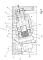
- the figures 1 and 2 illustrate a mixing valve 1 in which a mixing unit 2 is inserted.
- the mixing valve 1 is preferably designed to be installed on a basin of the sink or shower type, or more generally within a sanitary installation.
- the mixing valve 1 conventionally comprises a spout 3 from which a mixed flow of water illustrated by the arrow M1 is intended to be emitted.
- the valve 1 also comprises a body 4, which forms a hollow cylinder defining a main axis X4 which is intended to be arranged vertically when the valve is mounted on the sanitary installation.
- the axis X4 is arranged in a direction different from the vertical and is for example horizontal.
- the spout 3 forms a curved duct which extends from the body 4 obliquely with respect to the main axis X4, upwards, the curvature of the spout 3 making it possible to direct the mixed flow of water M1 towards the bottom.
- the mixed water flow thus progresses obliquely upwards within the spout according to the arrow M2 to the free end of the latter.
- the mixing valve 1 also includes a cold water inlet 5 which is visible at the figure 2 , and a hot water inlet 6 which is visible at the figure 1 , which are connected to the body 4 at a lower end of the latter.
- the cold water inlet 5 and the hot water inlet 6 are designed to be connected to conventional water supply means of the sanitary installation, which are not detailed. in the present description.
- the cold water progresses upwards in the inlet 5, according to the arrow F1, at a temperature Tf.
- the hot water progresses upwards in the inlet 6, according to the arrow C1, at a temperature Tc.
- the streams C1 and F1 are mixed within the mixing valve 1 to form the stream M1, with a temperature T M between Tf and Tc, and with a flow rate added to the streams C1 and F1.
- the mixing unit 2 is housed within the body 4, being inserted into the latter via an upper opening 9 of the body 4 along the main axis X4. It is in this mixing unit 2 that the mixing of the incoming flows F1 and C1 is carried out to form the outgoing flow M1.
- the mixing unit 2 has a generally cylindrical shape coaxial with the main axis X4.
- the mixing unit 2 comprises on the one hand a cartridge 11, which contains means 13 for mixing the first incoming flow F1 and the second incoming flow C1 to form the outgoing flow M1, and on the other hand an additional housing 15 which comprises an upper wall 46 by means of which said housing 15 is mounted to bear upwards against a lower wall 45 of the cartridge 11 along the main axis X4.
- the cartridge 11 is located in the upper part of the body 4, above the additional housing 15 which is located in the lower part of the body 4.
- the additional housing 15 has a lower face 24 by means of which it itself bears downwards against a bearing wall 23 of the body 4.
- the latter is substantially discoid and extends radially with respect to the body. 'main axis X4.
- the arrivals 5 and 6 of the inflows F1 and C1 pass through the support wall 23 to supply the additional box 15 through the lower face 24.
- the arrivals 5 and 6 are respectively connected, in a sealed manner, to a first inlet. 19 of the first incoming flow F1, and to a second inlet 21 of the second incoming flow C1 emerging on the surface of the lower face 24.
- the first incoming flow progresses according to the arrow F1 to the first inlet 19 and continues its course through the additional housing 15 from the bottom up according to the arrow F2 in a through duct 25 of the additional housing 15 extending parallel to the 'main axis X4 from the first inlet 19.
- the through duct 25 guides the first incoming flow F2 to a mixing chamber 27 of the cartridge 11, passing through the upper wall 46 of the housing 15.
- the mixing chamber 27 belongs to the mixing means 13.
- this chicane duct 32 includes a first part 31 substantially parallel to the main axis X4 and extending from the second inlet 21.
- the baffle duct 32 then comprises a part 29 which can be closed off by a shutter 87 which is described in more detail below, the closable part 29 extending the first part 31.
- the baffle duct 32 comprises a third part 35 substantially parallel to the main axis X4 leading the second incoming flow C2 to the cartridge 11 and extending the closable part 29.
- the third part 35 passes through the upper wall 46 of the housing 15.
- the closable part 29 extends obliquely with respect to the first part 31 and to the third part 35 so that the baffle duct 32 forms an “S”.
- the third part 35 opens into the mixing chamber 27.
- the mixing chamber 27 comprises an inlet 39 for the first flow F2, a second inlet 41 for the second flow C2, as well as an outlet 43 for the outgoing flow M3, as can be seen in particular on the figure. figure 5 , on which the additional box 15 is omitted.
- the inlets 39, 41 and the outlet 43 open out at the surface of the lower wall 45 of the cartridge 11.
- the lower wall 45 is generally discoid in shape centered on the main axis X4, the inlets 39 and 41 as well. that the output 43 being distributed around the main axis X4.
- the inlets 39, 41 and the outlet 43 are respectively surrounded by seals 44, 48 and 52, mounted on the surface of the lower wall 45, in order to ensure the tightness of the assembly between the cartridge 11 and the additional housing, by crushing the seals 44, 48 and 52 against the upper wall 46 of the housing 15.
- the first inlet 39 and the second inlet 41 are upstream of the mixing means 13, and the outlet 43 is downstream of the mixing means.
- the mixing means 13 comprise a set of mixing discs 13A, 13B and 13C, which are contained in the mixing chamber 27, as can be seen in the figures. figures 1 and 2 .
- the mixing discs 13A, 13B and 13C are in surface contact with each other and extend in planes orthogonal to the main axis X4.
- the mixing disc assembly comprises an upper disc 13A, an intermediate disc 13B and a lower disc 13C, the upper 13A and intermediate 13B discs being movable relative to the disc 13C which is fixed, the intermediate disc 13B being in sliding contact and waterproof with the 13C disc.
- the intermediate 13B and lower 13C discs comprise a system of channels and gills, not shown, which is connected to the inlets 39 and 41 as well as to the outlet 43 and which, depending on the relative position of the discs 13B and 13C, adjusts the respective flow of incoming flows F2 and C2 admitted into the set of disks through the inlets 39 and 41.
- the incoming flows circulate in the system of channels and gills and pass first to the through the lower disc 13C, then into the intermediate disc 13B.
- the incoming flows F3 and C3 then circulate again through the lower disc 13C from top to bottom.
- the outgoing flow M3 is at temperature T M , the ratio of the flow rates of the incoming flows F3 and C3 making it possible to adjust the temperature T M , and the value of the flow rates of the incoming flows F3 and C3 making it possible to adjust the flow rate of the outgoing flow M3.
- the passage section of the incoming flows F3 and C3 varies as a function of the relative position of the disks 13B and 13C, by placing the aforementioned channels and openings in communication.
- Ceramic discs and their channel system are not described in more detail because they constitute mixing means well known as such, and described for example in FR-B1-2 876 433 . It is also understood that, even if the implementation of a mixing chamber with ceramic discs is preferred, any known mixing means and usually used in cartridges for mixing valves can be used instead.
- the outgoing flow M3 formed by mixing within the mixing chamber 27 is then discharged out of the latter via the outlet 43, and out of the cartridge 11, into an outlet chamber 37 of the mixing valve 1, leading the outgoing flow M3 from top to bottom up to an outlet 47 formed through the support wall 23.
- the inlets 5 and 6 and the outlet 47 are distributed around the main axis X4.
- the additional housing 15 comprises a sealing ring 71 of circular shape which is centered on the main axis X4. In this case, the sealing ring 71 extends in a plane P71 orthogonal to the axis X4, projecting centrifugally from the axis X4, from the upper wall 46 of the housing 15 so as to be in sealed contact with the body 4.
- the sealing ring comprises a circular groove open radially outwards, within which is formed an O-ring crushed in contact with the body 4, as illustrated in the figures.
- the sealing ring 71 thus defines an upper part of the outlet chamber 37, the latter also being delimited laterally by the wall of the body 4, and at the bottom by the bearing wall 23.
- the outlet chamber 37, the through duct 25 and the baffle duct 32 are distributed regularly around the main axis X4.
- the outgoing flow M3 is thus discharged into a lower chamber 50, of the body 4 via the outlet 47.
- the lower chamber 50 is delimited at the top by the wall 23, laterally by the body 4 and at the bottom by a bottom 49 of the mixing valve 1.
- the bottom 49 is substantially discoid and orthogonal to the main axis X4, and closes the body 4 at the lower end of the latter.
- the outgoing flow M3 is led, according to the arrow M4, to the spout 3, via an access opening 51 made in the wall of the body 4 radially relative to the axis main X4, placing the lower chamber 50 in communication with the spout 3.
- the outgoing flow M4 becomes the outgoing flow M2, then the outgoing flow M1, mentioned in the above.
- the lever 7 is linked to the set of discs 13A, 13B and 13C, that is to say to the mixing means 13, by an operating mechanism which is not described in more detail, insofar as it is known as such.
- the cartridge 11 comprises a cover 53, which forms an outer casing wall of the cartridge 11, substantially cylindrical with a circular base around the main axis X4.
- the cover 53 contains the mixing means 13, laterally delimiting the chamber 27.
- the cover 53 also contains the base of the lever 7, the cartridge comprising a crown 63, attached to an upper end of the cover 53, by means of which a nut 65, centered around the main axis X4, presses the mixing unit 2 against the bearing wall 23.
- the nut 65 has an external thread which is screwed into an internal thread 69 of the upper opening 9 of the body 4, the thread 69 being centered on the axis X4.
- the mixing unit 2 also comprises thermostatic means, visible in particular on the figure 1 , which firstly comprise a thermostatic element 73, extending along a shutter axis X73 included in the plane of the figure 1 .
- the shutter axis X73 and the orthogonal plane P71 intersect. In other words, the shutter axis X73 is inclined relative to this plane P71 and crosses it.
- the closable part 29 of the baffle duct 32 extends substantially coaxially with the shutter axis X73.
- the shutter axis X73 forms an angle of inclination ⁇ 1 of between 10 ° and 45 ° with the orthogonal plane P71, and preferably equal to 13 °.
- the thermostatic element 73 includes a thermosensitive part 75 mounted in a housing 79 of the additional box 15.
- the housing 79 is a duct coaxial with the shutter axis X73, and which is provided in the additional housing 15 so as to connect the outlet chamber 37 and the baffle duct 32. The housing 79 thus places the outlet 47 in communication with the second inlet 21.
- the thermosensitive part 75 forms a fixed part of the thermostatic element 73 and comprises in particular, along the shutter axis X73, a cup 81 which projects from the housing 79 and which extends in the passage of the outgoing flow M3 , at the outlet 47.
- the cup 81 has a generally cylindrical shape with a circular base centered on the shutter axis X73, and contains a heat-expandable body which is for example a suitable wax.
- the cup 81 being in contact with the outgoing flow M3, the heat-expandable body expands and contracts as a function of the temperature T M of the outgoing flow M3.
- the heat-sensitive part 75 also comprises a guide 83, which extends the cup 81 along the shutter axis X73, and through which the heat-sensitive part 75 is mounted in the housing 79.
- the guide 83 has a shape of screw, with an external thread, around the shutter axis X73, and extends at least partially within the housing 79.
- the guide 83 is screwed into a support ring 84 provided with an internal thread, coaxial with the axis X73, the support ring 84 being itself fixed within an end 90 of the housing 79.
- the end 90 forms an end part of the housing 79 extending from the side of the outlet 47, in contact with the outlet chamber 37.
- the support ring 84 is partially inserted into the end 90, and has a seal 92 with the housing 79, so as to close this last in a sealed manner and thus prevent any transfer of water from the second flow C2 into the outlet 47 via the housing 79.
- the support ring 84 is fixed to the housing 79 by means of fixing elements 94 shown diagrammatically on the figure 4 , like screw.
- the fixing elements 94 are implanted in a wall of the chamber 37, which forms the periphery of the end 90.
- the thermostatic element 73 is thus housed in the housing 79 so as to seal off the communication between the outlet 47 and the second entry 21.
- the thermostatic element 73 also comprises a movable part 77, which forms a cylindrical piston coaxial with the shutter axis X73.
- the mobile part 77 is mounted within the guide 83, so as to be able to translate with respect to the thermosensitive part 75 away from the thermosensitive part 75, in the direction of the baffle duct 32, along the shutter axis X73 under the action of the thermo-expandable body contained in the cup 81.
- a shutter 87 belonging to the thermostatic element 73, is provided within the closable part 29, and is designed to be moved in translation along the shutter axis X73 by the movable part 77.
- the shutter 87 is arranged. relative to the movable part 77 so that the latter can push the shutter 87 to a closed position of the second inlet 21, in which a seal 26 of the shutter 87, formed by for example by an external O-ring, closes the closable part 29.
- the movable part 77 is in contact with the shutter 87 so as to push the latter away from the thermosensitive part 75 in a direction D1 parallel to the X73 axis, under the action of the thermally expandable body contained in the cup 81. Due to the inclination of the X73 axis relative to the plane P71, the thermostatic element 73 is further from the mixing means 13 than shutter 87.
- the shutter 87 is mounted in compression between the free end of the movable part 77 and a return spring 89.
- the latter is itself mounted in compression between the shutter 87 and an opposite wall 28 of the closable part 29 of the shutter. baffle duct 32.
- the opposite wall 28 extends in a plane orthogonal to the axis X73.
- the return spring 89 is therefore a compression spring, designed to return the shutter 87 in a direction D2 opposite to D1, to an open position of the baffle duct 32 and therefore of the second inlet 21.
- the shutter 87 is therefore configured to shut off the second inlet 21 by shutting off the closable part 29, according to a degree of shutter which varies as a function of the expansion of the thermo-expandable body, and therefore of the temperature T M , to vary the flow rate of the second incoming stream C2 accordingly.
- a predetermined threshold for example 50 ° C
- the flow C2 is completely, or at least partially, interrupted by closing off the second inlet 21.
- the thermostatic means, and in particular the shutter 87 constitute a means separate from the mixing means 13 described above.
- the thermostatic means advantageously have a safety, anti-scalding function, reducing or cutting off the incoming flow C2 when the outgoing flow M3 is of too high a temperature.
- the mixing unit 2 is configured to be inserted into the body 4 of the mixing valve 1 via the upper opening 9. Before this step of inserting the unit 2, the outlet chamber 37 is opened and forms a clearance space, due to the absence of the body 4 of the mixing valve 1.
- the mounting of the thermostatic element 73 can therefore be carried out by inserting the latter into the housing 79 in the direction D1, by the end 90, which therefore constitutes an “insertion end”.
- the clearance space of the chamber 37 is shaped so that the thermostatic element 73, the shutter 87 and the spring 89 can be placed in this clearance space, along the axis X73, then be pushed in the direction D1 in order to be inserted into the housing 79 by the insertion end 90, without requiring a separation of the additional housing 15 and the cartridge 11.
- This configuration of the chamber 37 is made possible due to the 'inclination of the axis X73 relative to the plane P71, thanks to which the thermostatic means pass next to the sealing ring 71 when they are put in translation along the axis X73 in the chamber 37.
- a notch 72 is provided in the sealing ring 71 at a point on the circumference of the latter. This notch 72 has a cylindrical profile coaxial with the axis X73, and has a radius DR.
- the radius DR is greater than the radial size, that is to say the maximum radius with respect to the axis X73, of the thermostatic means.
- the aforementioned thermostatic means are mounted within the housing 79, they are crossed by the plane P71 and surrounded by the sealing ring 71.
- the clearance space extends at least over one cylinder coaxial with the axis X73, starting at the level of the insertion end 90 in the direction of the exit chamber 37 and having a radius equal to the radius DR.
- the inclination of the axis X73 implies that the sealing ring 71 can be placed at a relatively small distance from the underside 24, despite the size of the thermostatic means and the constraints associated with their mounting within the mixing unit 2.
- this mixing unit 2 is particularly compact and is suited to the geometry of the existing mixing valves.
- the inclination of the axis X73 relative to the plane P71 is such that the thermostatic element 73 is less distant from the mixing means 13 than is the shutter 87.
- the angle ⁇ 1 is for example between -45 ° and -10 °, preferably -13 °.
- a reverse arrangement to that shown on the figures 1 to 5 is adopted for the thermostatic element 73 and the shutter 87, so that the plane P71 and the axis X73 intersect.
- the inclination of the axis X73 relative to the plane P71 also implies that the sealing ring 71 can be placed at a relatively small distance from the lower face 24.
- the angle ⁇ 1 is preferably between -45 ° and 45 °, while being non-zero.
- the figure 6 illustrates a mixing unit 102 according to a second embodiment and which has similar characteristics with the mixing unit 2 of the first embodiment described above, illustrated in figures 1 to 5 , these similar characteristics being designated by an identical line in the drawing, and / or reference numerals increased by 100.
- the description which follows therefore centers on the differences between the first and the second embodiment.
- the mixing unit 102 includes a first inlet for a first incoming stream, not visible on the figure 6 , as well as inlets 121 and 141 for a second incoming flow C2, a baffle duct 132, with a closable part 129, mixing means 113 to form an outgoing flow M3, an outlet 143 with an outlet chamber 137 and a housing 179.
- the mixing unit 102 also comprises a control member 107, thermostatic means comprising on the one hand a thermostatic element 173 including both a thermosensitive part 175 and a movable part 177, and on the other hand a shutter 187, with a return spring 189.
- the movable part 177 is movable in translation along a shutter axis X173, secant with respect to a plane P171 orthogonal to a main axis X104 defined by the general cylindrical shape of the mixing unit 102.
- the plane P171 and the axis X173 define an angle of inclination ⁇ 101.
- the mixing unit 102 comprises a sealing ring 171 with a body 4 of the mixing valve 1, the sealing ring extending in the plane P171 projecting centrifugally with respect to the main axis X104.
- the mixing unit 102 is integrated in the same body 4 of the mixing valve 1 as that of the figures 1 to 5 .
- the mixing unit 102 includes a cartridge 111 and a additional housing 115.
- the additional housing 115 of the mixing unit 102 is integral with the cartridge 111, or is at least permanently attached to this cartridge 111.
- the mixing unit 102 comprises a single part 145 replacing both a lower wall 45 and the upper wall 46 of the mixing unit 2.
- the part 145 also forms, in one piece, a cover 153 of the cartridge 111, the sealing ring 171, as well as the baffle duct 132, the outlet chamber 137 and the through duct, not visible on the figure 6 .
- the mixing unit 102 is thus particularly easy to manufacture, insofar as it is not necessary to assemble an additional housing on a cartridge, which dispenses with the use of gaskets. of the type of seals 44, 48 and 52 of the mixing unit 2.
- This part 145 can be obtained for example by molding.
- the assembly of the thermostatic means within the mixing unit 102 can be carried out as in the case of unit 2, thanks to the inclination of the axis X173, which makes it possible to provide a clearance space under the sealing ring 171.
- the arrival 5 corresponds to an arrival of a first incoming flow F1 of fluid having a first temperature Tf
- the arrival 6 corresponds to an arrival of a second incoming flow C1 of fluid having a second temperature. Tc which is greater than the first temperature Tf.
- the fluids of the first inflow F1 and of the second inflow C1 are preferably identical and liquid, but may however be of a different nature.
- the water escaping from the spout 3 thus corresponds to an outgoing flow M1 of fluid, which is formed by mixing the first and second incoming flows F1 and C1 within the mixing valve 1.
Landscapes
- Engineering & Computer Science (AREA)
- General Engineering & Computer Science (AREA)
- Mechanical Engineering (AREA)
- Physics & Mathematics (AREA)
- General Physics & Mathematics (AREA)
- Automation & Control Theory (AREA)
- Health & Medical Sciences (AREA)
- Life Sciences & Earth Sciences (AREA)
- Hydrology & Water Resources (AREA)
- Public Health (AREA)
- Water Supply & Treatment (AREA)
- Multiple-Way Valves (AREA)
- Accessories For Mixers (AREA)
- Temperature-Responsive Valves (AREA)
Description
- La présente invention concerne une unité de mélange et un robinet mitigeur comprenant une telle unité de mélange.
- L'invention se rapporte au domaine de la robinetterie d'usage sanitaire. En particulier, les robinets dits « mitigeurs » permettent d'émettre un flux mitigé d'eau courante par mélange d'un flux d'eau chaude et d'un flux d'eau froide au sein d'une cartouche montée dans le corps du robinet. Le débit respectif des flux d'eau froide et d'eau chaude admis dans la cartouche peuvent être réglés à l'aide d'un levier de commande, afin de permettre un réglage de la température du flux mitigé par rotation du levier autour d'un axe, et du débit du flux mitigé par rotation de levier autour d'un deuxième axe.
- La cartouche comprend dans la plupart des cas une paire de disques céramiques ajourés, l'un étant fixe, et l'autre étant mobile sous l'action du levier tout en étant en contact plan, glissant et étanche avec le disque fixe. En fonction de la position du disque mobile sur le disque fixe, des canaux sont formés pour permettre l'admission des flux d'eau froide et chaude au sein de la cartouche, avec un débit plus ou moins important, et ainsi entraîner leur mélange pour la formation du flux mitigé.
- Certaines cartouches connues peuvent être dotées d'un boîtier additionnel séparé, et qui est rapporté contre la cartouche. Par exemple, le brevet
FR-B-2 876 433 - Cependant, l'encombrement spatial que représente un tel module additionnel peut rendre difficile son adaptation au sein de certains robinets mitigeurs existants, qui offrent un espace d'accueil limité pour la cartouche et le module additionnel.
-
WO 2015/086749 A1 décrit une cartouche comprenant deux entrées d'eau chaude et d'eau froide, une chambre de sortie, ainsi que des disques de mélange. Cette cartouche comprend également un élément thermostatique, avec une partie thermosensible disposée dans la chambre de sortie, et une partie mobile en translation par rapport à la partie thermosensible, de façon coaxiale avec un axe principal de la cartouche. Cette cartouche connue comprend également un tiroir obturateur, lié à la partie thermosensible, de façon à assurer une régulation thermostatique de la température du flux d'eau sortant. Le tiroir obturateur est conçu pour obturer le passage de l'eau froide et de l'eau chaude au niveau d'une chambre de sortie, située en aval des disques de mélange, et ne permet pas une obturation de l'entrée d'eau chaude, située en amont des disques de mélange. Cette cartouche connue ne comprend pas d'obturateur de l'entrée d'eau chaude. L'axe de translation du tiroir obturateur étant coaxial à l'axe de la cartouche, le système de régulation thermostatique représente un encombrement relativement important en partie basse de la cartouche. -
FR 3 003 046 A1 WO 2015/086749 A1 . - Le document
DE 197 16 307 décrit également un dispositif comprenant un système de régulation thermostatique. - Par conséquent, l'invention vise à porter remède aux inconvénients de l'art antérieur en proposant une nouvelle unité de mélange qui, tout en étant facile à fabriquer, présente une compacité suffisante pour s'adapter à la plupart des robinets mitigeurs existants.
- L'invention a pour objet une unité de mélange pour un robinet mitigeur selon la revendication 1.
- Grâce à l'invention, les moyens thermostatiques sont disposés en biais au sein de l'unité de mélange, de sorte que la compacité de l'unité de mélange est améliorée selon l'axe principal. Cette compacité est assurée, alors même que l'on prévoit à la fois des moyens de mélange et des moyens thermostatiques visant à obturer au moins partiellement la deuxième entrée en fonction de la température du flux sortant.
- Selon d'autres caractéristiques avantageuses de l'invention, prises isolément ou en combinaison :
- l'axe d'obturation forme un angle d'inclinaison non nul compris entre -45° et 45° avec le plan orthogonal ;
- l'angle d'inclinaison est compris entre -45° et -10° ou entre 10° et 45° ;
- l'unité de mélange comprend un logement, qui met en communication la sortie avec la deuxième entrée le long de l'axe d'obturation, et dans lequel au moins une partie des moyens thermostatiques est logée, de façon à obturer de manière étanche la communication entre la sortie et la deuxième entrée ;
- le logement présente une extrémité d'insertion des moyens thermostatiques en son sein, l'extrémité d'insertion étant disposée du côté de la sortie, l'unité de mélange définissant un espace de dégagement des moyens thermostatiques, par l'intermédiaire duquel les moyens thermostatiques peuvent être montés dans le logement par translation des moyens thermostatiques le long de l'axe d'obturation jusqu'à insertion d'au moins une partie des moyens thermostatiques au sein du logement par l'intermédiaire de l'extrémité d'insertion ;
- l'unité de mélange comprend une couronne d'étanchéité de l'unité de mélange avec un corps de robinet mitigeur, la couronne d'étanchéité s'étendant dans le plan orthogonal, les moyens thermostatiques étant traversés par le plan orthogonal et entourés par la couronne d'étanchéité ;
- l'unité de mélange comprend une cartouche, renfermant les moyens de mélange, et un boîtier additionnel, qui est monté en appui contre la cartouche et qui inclut les moyens thermostatiques et la couronne d'étanchéité ;
- l'unité de mélange comprend une face inférieure en surface de laquelle la première entrée et la deuxième entrée débouchent, la deuxième entrée étant prolongée, vers l'intérieur de l'unité de mélange, par un conduit en chicane comprenant une partie obturable par l'obturateur, la partie obturable s'étendant sensiblement de façon coaxiale avec l'axe d'obturation, le conduit en chicane reliant la deuxième entrée aux moyens de mélange ;
- l'ensemble de disques de mélange comprend un disque supérieur et un disque intermédiaire, l'organe de commande actionnant le disque supérieur et le disque intermédiaire : en rotation, autour de l'axe principal ou autour d'un premier axe, qui est parallèle à l'axe principal, pour régler le rapport entre le débit du premier flux entrant et du deuxième flux entrant et donc la température du flux sortant ; et en translation, selon un deuxième axe, qui est orthogonal à l'axe principal, pour faire varier équitablement le débit du premier flux entrant et du deuxième flux entrant, pour régler le débit du flux sortant ;
- l'organe de commande comprend un levier permettant de commander à la fois le débit et la température du flux sortant par réglage des débits du premier flux entrant et du deuxième flux entrant, le levier étant : pivotant autour de l'axe principal pour faire varier la température du flux sortant ; et pivotant autour d'un troisième axe qui est orthogonal à l'axe principal pour régler le débit du flux sortant ; et
- le premier flux entrant provenant de la première entrée et le deuxième flux entrant provenant de la deuxième entrée sont mis en contact au cours de leur passage au sein des moyens de mélange pour être mélangés et former le flux sortant, le flux sortant étant alors évacué via la sortie.
- L'invention concerne également un robinet mitigeur équipé d'une unité de mélange telle que définie ci-avant.
- L'invention sera mieux comprise à la lecture de la description qui va suivre, donnée uniquement à titre d'exemple non limitatif et faite en se référant aux dessins dans lesquels :
- les
figures 1 et2 sont des coupes longitudinales d'un robinet mitigeur comprenant une unité de mélange selon un premier mode de réalisation conforme à l'invention ; - la
figure 3 est une vue d'un détail de lafigure 1 , à plus grande échelle, selon le cadre III ; - la
figure 4 est une vue en perspective du dessous de l'unité de mélange desfigures 1 à 3 , sur laquelle sont représentés des plans I-I et II-II correspondent aux plans de coupe respectives desfigures 1 et2 ; - la
figure 5 est une vue similaire à celle de lafigure 4 dans laquelle un boîtier additionnel de l'unité de mélange est omis ; et - la
figure 6 est une vue, similaire à celle de lafigure 1 , d'un robinet mitigeur comprenant une unité de mélange selon un deuxième mode de réalisation conforme à l'invention. - Les
figures 1 et2 illustrent un robinet mitigeur 1 dans lequel est insérée une unité de mélange 2. Le robinet mitigeur 1 est préférentiellement conçu pour être installé sur un bac du genre évier ou douche, ou plus généralement au sein d'une installation sanitaire. Le robinet mitigeur 1 comprend, de manière classique, un bec 3 à partir duquel un flux d'eau mitigé illustré par la flèche M1 est destiné à être émis. Le robinet 1 comprend également un corps 4, lequel forme un cylindre creux définissant un axe principal X4 qui est destiné à être disposé verticalement lorsque le robinet est monté sur l'installation sanitaire. - Par commodité, la suite de la description est orientée par rapport à l'axe principal X4, en considérant que les termes « supérieur » et « haut » correspondent à une direction axiale tournée vers la partie haute de la
figure 1 , tandis que les termes « inférieur » et « bas » correspondent à une direction axiale de sens opposé. - En variante non illustrée, l'axe X4 est disposé selon une direction différente de la verticale et est par exemple horizontal.
- Le bec 3 forme un conduit courbé qui s'étend à partir du corps 4 à l'oblique par rapport à l'axe principal X4, vers le haut, la courbure du bec 3 permettant d'orienter le flux d'eau mitigé M1 vers le bas. Le flux d'eau mitigé progresse ainsi à l'oblique vers le haut au sein du bec selon la flèche M2 jusqu'à l'extrémité libre de ce dernier.
- Le robinet mitigeur 1 comprend également une arrivée d'eau froide 5 qui est visible à la
figure 2 , et une arrivée d'eau chaude 6 qui est visible à lafigure 1 , qui sont connectées au corps 4 au niveau d'une extrémité basse de ce dernier. L'arrivée d'eau froide 5 et l'arrivée d'eau chaude 6 sont prévues pour être connectées à des moyens d'alimentation en eau classiques de l'installation sanitaire, lesquels ne sont pas détaillés dans la présente description. L'eau froide progresse vers le haut dans l'arrivée 5, selon la flèche F1, à une température Tf. L'eau chaude progresse quant à elle vers le haut dans l'arrivée 6, selon la flèche C1, à une température Tc. Les flux C1 et F1 sont mélangés au sein du robinet mitigeur 1 pour former le flux M1, d'une température TM comprise entre Tf et Tc, et de débit additionné des flux C1 et F1. - L'unité de mélange 2 est logée au sein du corps 4, en étant insérée dans ce dernier par l'intermédiaire d'une ouverture supérieure 9 du corps 4 le long de l'axe principal X4. C'est dans cette unité de mélange 2 qu'est effectué le mélange des flux entrants F1 et C1 pour former le flux sortant M1.
- L'unité de mélange 2 présente une forme générale cylindrique coaxiale avec l'axe principal X4. L'unité de mélange 2 comprend d'une part une cartouche 11, qui renferme des moyens 13 de mélange du premier flux entrant F1 et du deuxième flux entrant C1 pour former le flux sortant M1, et d'autre part un boîtier additionnel 15 qui comprend une paroi supérieure 46 par l'intermédiaire de laquelle ledit boîtier 15 est monté en appui vers le haut contre une paroi inférieure 45 de la cartouche 11 le long de l'axe principal X4. Ainsi, la cartouche 11 est située en partie supérieure du corps 4, au-dessus du boîtier additionnel 15 qui est situé en partie inférieure du corps 4.
- Le boîtier additionnel 15 présente une face inférieure 24 par l'intermédiaire de laquelle il est lui-même en appui vers le bas contre une paroi d'appui 23 du corps 4. Cette dernière est sensiblement discoïde et s'étend radialement par rapport à l'axe principal X4. Les arrivées 5 et 6 des flux entrants F1 et C1 traversent la paroi d'appui 23 pour alimenter le boîtier additionnel 15 par la face inférieure 24. En pratique, les arrivées 5 et 6 sont respectivement connectées, de façon étanche, à une première entrée 19 du premier flux entrant F1, et à une deuxième entrée 21 du deuxième flux entrant C1 débouchant en surface de la face inférieure 24.
- Tel qu'illustré à la
figure 2 , le premier flux entrant progresse selon la flèche F1 jusqu'à la première entrée 19 et poursuit sa course au travers du boîtier additionnel 15 de bas en haut selon la flèche F2 dans un conduit traversant 25 du boîtier additionnel 15 s'étendant parallèlement à l'axe principal X4 à partir de la première entrée 19. Le conduit traversant 25 guide le premier flux entrant F2 jusqu'à une chambre de mélange 27 de la cartouche 11, en traversant la paroi supérieure 46 du boîtier 15. La chambre de mélange 27 appartient aux moyens de mélange 13. Parallèlement, tel qu'illustré à lafigure 1 , le deuxième flux entrant entre dans le boîtier additionnel 15 par l'intermédiaire de la deuxième entrée 21, et circule de bas en haut selon la flèche C2 au travers du boîtier additionnel 15 dans un conduit en chicane 32 qui s'étend généralement de bas en haut à partir de la deuxième entrée 21. En l'espèce ce conduit en chicane 32 comprend une première partie 31 sensiblement parallèle à l'axe principal X4 et s'étendant à partir de la deuxième entrée 21. Le conduit en chicane 32 comprend ensuite une partie obturable 29, par un obturateur 87 qui est décrit plus en détail ci-après, la partie obturable 29 prolongeant la première partie 31. Enfin, le conduit en chicane 32 comprend une troisième partie 35 sensiblement parallèle à l'axe principal X4 conduisant le deuxième flux entrant C2 jusqu'à la cartouche 11 et prolongeant la partie obturable 29. La troisième partie 35 traverse la paroi supérieure 46 du boîtier 15. La partie obturable 29 s'étend de façon oblique par rapport à la première partie 31 et à la troisième partie 35 de sorte que le conduit en chicane 32 forme un « S ». La troisième partie 35 débouche dans la chambre de mélange 27. Ainsi, les deux flux entrant F2 et C2 sont admis au sein de la chambre de mélange 27 de la cartouche 11 pour y être mélangés et former un flux sortant M3 destiné à former le flux M1. - La chambre de mélange 27 comprend une entrée 39 pour le premier flux F2, une deuxième entrée 41 pour le deuxième flux C2, ainsi qu'une sortie 43 pour le flux sortant M3, comme cela est notamment visible sur la
figure 5 , sur laquelle le boîtier additionnel 15 est omis. Les entrées 39, 41 et la sortie 43 débouchent en surface de la paroi inférieure 45 de la cartouche 11. En l'espèce, la paroi inférieure 45 est de forme généralement discoïde centrée sur l'axe principal X4, les entrées 39 et 41 ainsi que la sortie 43 étant réparties autour de l'axe principal X4. Les entrées 39, 41 et la sortie 43 sont respectivement entourées par des joints d'étanchéité 44, 48 et 52, montés en surface de la paroi inférieure 45, afin d'assurer l'étanchéité de l'assemblage entre la cartouche 11 et le boîtier additionnel, par écrasement des joints 44, 48 et 52 contre la paroi supérieure 46 du boîtier 15. Selon le sens de circulation des flux, la première entrée 39 et la deuxième entrée 41 sont en amont des moyens de mélange 13, et la sortie 43 est en aval des moyens de mélange. - Dans l'exemple illustré, les moyens de mélange 13 comprennent un ensemble de disques de mélange 13A, 13B et 13C, qui sont contenus dans la chambre de mélange 27, comme cela est visible sur les
figures 1 et2 . Les disques de mélange 13A, 13B et 13C sont en contact surfaciques les uns avec les autres et s'étendent dans des plans orthogonaux à l'axe principal X4. L'ensemble de disques de mélange comprend un disque supérieur 13A, un disque intermédiaire 13B et un disque inférieur 13C, les disques supérieur 13A et intermédiaire 13B étant mobiles par rapport au disque 13C qui est fixe, le disque intermédiaire 13B étant en contact glissant et étanche avec le disque 13C. Les disques intermédiaire 13B et inférieur 13C comprennent un système de canaux et d'ouïes, non représenté, qui est connecté aux entrées 39 et 41 ainsi qu'à la sortie 43 et qui, en fonction de la position relative des disques 13B et 13C, règle le débit respectif des flux entrants F2 et C2 admis au sein de l'ensemble de disques par les entrées 39 et 41. Tel que représentés par les flèches F3 et C3, les flux entrants circulent dans le système de canaux et d'ouïes et passent d'abord au travers du disque inférieur 13C, puis dans le disque intermédiaire 13B. Les flux entrants F3 et C3 circulent ensuite à nouveau au travers du disque inférieur 13C de haut en bas. Au cours de leur passage au sein des disques 13A, 13B et 13C, où les flux entrants F3 et C3 sont mis en contact pour être mélangés et former le flux sortant M3. Le flux sortant M3 est à température TM, le rapport des débits des flux entrants F3 et C3 permettant de régler la température TM, et la valeur des débits des flux entrants F3 et C3 permettant de régler le débit du flux sortant M3. En pratique, la section de passage des flux entrants F3 et C3 varie en fonction de la position relative des disques 13B et 13C, par mise en communication des canaux et des ouïes susmentionnés. Les disques céramiques et leur système de canaux ne sont pas décrits plus en détails car ils constituent des moyens de mélange bien connus en tant que tels, et décrits par exemple dansFR-B1-2 876 433 - Le flux sortant M3 formé par mélange au sein de la chambre de mélange 27 est alors évacué hors de cette dernière via la sortie 43, et hors de la cartouche 11, jusque dans une chambre de sortie 37 du robinet mitigeur 1, conduisant le flux sortant M3 de haut en bas jusqu'à une sortie 47 ménagée au travers de la paroi d'appui 23. Les arrivées 5 et 6 et la sortie 47 sont réparties autour de l'axe principal X4. Le boîtier additionnel 15 comprend une couronne d'étanchéité 71 de forme circulaire qui est centrée sur l'axe principal X4. En l'espèce, la couronne d'étanchéité 71 s'étend dans un plan orthogonal P71 par rapport à l'axe X4, en faisant saillie de façon centrifuge par rapport à l'axe X4, à partir de la paroi supérieure 46 du boîtier 15 de manière à être en contact étanche le corps 4. En l'espèce, la couronne d'étanchéité comprend une gorge circulaire ouverte radialement vers l'extérieur, au sein de laquelle est ménagé un joint torique écrasé au contact du corps 4, comme illustré aux figures. La couronne d'étanchéité 71 délimite ainsi une partie supérieure de la chambre de sortie 37, cette dernière étant également délimitée latéralement par la paroi du corps 4, et en bas par la paroi d'appui 23. Comme cela est visible à la
figure 4 , la chambre de sortie 37, le conduit traversant 25 et le conduit en chicane 32 sont répartis régulièrement autour de l'axe principal X4. Tel qu'illustré auxfigures 1 et2 , le flux sortant M3 est ainsi déversé au sein d'une chambre basse 50, du corps 4 par l'intermédiaire de la sortie 47. La chambre basse 50 est délimitée en haut par la paroi 23, latéralement par le corps 4 et en bas par un fond 49 du robinet mitigeur 1. Le fond 49 est sensiblement discoïde et orthogonal à l'axe principal X4, et ferme le corps 4 à l'extrémité inférieure de ce dernier. Dans la chambre basse 50, le flux sortant M3 est conduit, selon la flèche M4, jusqu'au bec 3, par l'intermédiaire d'une ouverture d'accès 51 ménagée dans la paroi du corps 4 radialement par rapport à l'axe principal X4, mettant en communication la chambre basse 50 avec le bec 3. Dans le bec 3, le flux sortant M4 devient le flux sortant M2, puis le flux sortant M1, mentionnés dans ce qui précède. - L'unité de mélange 2 comprend en outre un levier 7 qui est monté mobile au sommet de la cartouche 11, de manière à dépasser du corps 4 par l'intermédiaire de l'ouverture supérieure 9, pour permettre à un utilisateur d'actionner le levier 7. L'actionnement du levier 7 permet de commander les moyens de mélange 13, et en particulier de mouvoir les disques supérieur 13A et intermédiaire 13B en rotation autour d'un axe parallèle à l'axe principal X4, ou autour de l'axe X4 lui-même, et en translation selon un axe X13 qui est orthogonal à l'axe principal X4. De manière générale, le levier 7 forme un organe de commande pour actionner au moins l'un des disques 13A, 13B et 13C, et ainsi commander le débit respectif du premier flux entrant F1 et du deuxième flux entrant C1. Ainsi, l'organe de commande 7 permet de régler à la fois la température et le débit du flux sortant M1 par réglage de la position relative des disques de l'ensemble de disques 13A, 13B et 13C. Le robinet mitigeur 1 et la cartouche 11 peuvent ainsi être qualifiés de « monocommandes » dans la mesure où le levier 7 permet de commander à la fois le débit et la température du flux sortant M1 par réglage des débits des flux entrants F1 et C1. En pratique, le levier 7 est :
- pivotant autour de l'axe principal X4, ce qui entraîne une rotation des disques supérieur 13A et 13B autour de ce même axe, afin de régler le rapport entre le débit du premier et du deuxième flux entrants F1 et C1 et donc la température du flux sortant M1, et
- pivotant autour d'un deuxième axe X7 qui est orthogonal à l'axe principal X4 afin de translater les disques supérieurs 13A et 13B le long de l'axe X13 et de faire varier équitablement le débit du premier et du deuxième flux, pour régler le débit du flux sortant.
- Le levier 7 est lié à l'ensemble de disques 13A, 13B et 13C, c'est-à-dire aux moyens de mélange 13, par un mécanisme de manœuvre qui n'est pas décrit plus en détail, dans la mesure où il est connu en tant que tel.
- La cartouche 11 comprend un capot 53, qui forme une paroi d'enveloppe extérieure de la cartouche 11, sensiblement cylindrique à base circulaire autour de l'axe principal X4. Le capot 53 renferme les moyens de mélange 13, en délimitant latéralement la chambre 27. Le capot 53 renferme également la base du levier 7, la cartouche comprenant une couronne 63, rapportée sur une extrémité supérieure du capot 53, par l'intermédiaire de laquelle un écrou 65, centré autour de l'axe principal X4, plaque l'unité de mélange 2 contre la paroi d'appui 23. En pratique, l'écrou 65 comporte un filetage extérieur qui est vissé dans un filetage intérieur 69 de l'ouverture supérieure 9 du corps 4, le filetage 69 étant centré sur l'axe X4.
- L'unité de mélange 2 comprend également des moyens thermostatiques, visibles notamment sur la
figure 1 , qui comprennent en premier lieu un élément thermostatique 73, s'étendant selon un axe d'obturation X73 compris dans le plan de lafigure 1 . L'axe d'obturation X73 et le plan orthogonal P71 sont sécants. En d'autres termes, l'axe d'obturation X73 est incliné par rapport à ce plan P71 et le traverse. La partie obturable 29 du conduit en chicane 32 s'étend sensiblement de façon coaxiale avec l'axe d'obturation X73. De préférence, l'axe d'obturation X73 forme un angle d'inclinaison β1 compris entre 10° et 45° avec le plan orthogonal P71, et de préférence égal à 13°. - Comme cela est notamment visible à la
figure 3 , le long de l'axe d'obturation X73, l'élément thermostatique 73 inclut une partie thermosensible 75 montée dans un logement 79 du boîtier additionnel 15. Le logement 79 est un conduit coaxial avec l'axe d'obturation X73, et qui est ménagé dans le boîtier additionnel 15 de façon à relier la chambre de sortie 37 et le conduit en chicane 32. Le logement 79 met ainsi en communication la sortie 47 avec la deuxième entrée 21. - La partie thermosensible 75 forme une partie fixe de l'élément thermostatique 73 et comprend en particulier, le long de l'axe d'obturation X73, une coupelle 81 qui dépasse du logement 79 et qui s'étend dans le passage du flux sortant M3, à la sortie 47. La coupelle 81 présente une forme généralement cylindrique à base circulaire centrée sur l'axe d'obturation X73, et renferme un corps thermo-dilatable qui est par exemple une cire adaptée. La coupelle 81 étant en contact avec le flux sortant M3, le corps thermo-dilatable se dilate et se contracte en fonction de la température TM du flux sortant M3.
- La partie thermosensible 75 comprend également un guide 83, qui prolonge la coupelle 81 le long de l'axe d'obturation X73, et par l'intermédiaire duquel la partie thermosensible 75 est montée dans le logement 79. Le guide 83 présente une forme de vis, avec un filetage extérieur, autour de l'axe d'obturation X73, et s'étend au moins en partie au sein du logement 79. En l'espèce, le guide 83 est vissé au sein d'une bague de support 84 pourvue d'un filetage intérieur, coaxial avec l'axe X73, la bague de support 84 étant elle-même fixée au sein d'une extrémité 90 du logement 79. L'extrémité 90 forme une partie extrémale du logement 79 s'étendant du côté de la sortie 47, en contact avec la chambre de sortie 37. La bague de support 84 est partiellement insérée dans l'extrémité 90, et présente une garniture d'étanchéité 92 avec le logement 79, de façon à obturer ce dernier de façon étanche et ainsi prévenir tout transfert d'eau du deuxième flux C2 dans la sortie 47 via le logement 79. La bague 84 de support est fixée au logement 79 à l'aide d'éléments de fixation 94 schématisés sur la
figure 4 , du genre vis. Les éléments de fixation 94 sont implantés dans une paroi de la chambre 37, laquelle forme la périphérie de l'extrémité 90. L'élément thermostatique 73 est ainsi logé dans le logement 79 de façon à obturer de manière étanche la communication entre la sortie 47 et la deuxième entrée 21. - L'élément thermostatique 73 comprend également une partie mobile 77, qui forme un piston cylindrique coaxial avec l'axe d'obturation X73. La partie mobile 77 est montée au sein du guide 83, de façon à pouvoir translater par rapport à la partie thermosensible 75 à l'écart de la partie thermosensible 75, en direction du conduit en chicane 32, selon l'axe d'obturation X73 sous l'action du corps thermo-dilatable contenu dans la coupelle 81.
- Un obturateur 87, appartenant à l'élément thermostatique 73, est prévu au sein de la partie obturable 29, et est conçu pour être déplacé en translation selon l'axe d'obturation X73 par la partie mobile 77. L'obturateur 87 est agencé par rapport à la partie mobile 77 de manière à ce que cette dernière puisse pousser l'obturateur 87 jusqu'à une position d'obturation de la deuxième entrée 21, dans laquelle une garniture d'étanchéité 26 de l'obturateur 87, formée par exemple par un joint torique externe, vient obturer la partie obturable 29. En l'espèce, la partie mobile 77 est en contact avec l'obturateur 87 de façon à pousser ce dernier à l'écart de la partie thermosensible 75 dans une direction D1 parallèle à l'axe X73, sous l'action du corps thermodilatable contenu dans la coupelle 81. Du fait de l'inclinaison de l'axe X73 par rapport au plan P71, l'élément thermostatique 73 est plus éloigné des moyens de mélange 13 que ne l'est l'obturateur 87.
- L'obturateur 87 est monté en compression entre l'extrémité libre de la partie mobile 77 et un ressort de rappel 89. Ce dernier est lui-même monté en compression entre l'obturateur 87 et une paroi opposée 28 de la partie obturable 29 du conduit en chicane 32. La paroi opposée 28 s'étend dans un plan orthogonal par rapport à l'axe X73. Le ressort de rappel 89 est donc un ressort de compression, conçu pour rappeler l'obturateur 87 dans une direction D2 opposée à D1, jusqu'à une position d'ouverture du conduit en chicane 32 et donc de la deuxième entrée 21.
- L'obturateur 87 est donc configuré pour obturer la deuxième entrée 21 par obturation de la partie obturable 29, selon un degré d'obturation variable en fonction de la dilatation du corps thermo-dilatable, et donc de la température TM, pour faire varier le débit du deuxième flux entrant C2 en conséquence. Lorsque la température TM atteint un seuil prédéterminé, par exemple 50°C, le flux C2 est totalement, ou au moins partiellement, interrompu par obturation de la deuxième entrée 21. Les moyens thermostatiques, et en particulier l'obturateur 87, constituent un moyen séparé des moyens de mélange 13 décrits ci-avant. Les moyens thermostatiques ont avantageusement une fonction sécuritaire, anti-brûlure, réduisant ou coupant le flux entrant C2 lorsque le flux sortant M3 est de température trop élevée.
- L'unité de mélange 2 est configurée pour être insérée dans le corps 4 du robinet mitigeur 1 par l'intermédiaire de l'ouverture supérieure 9. Avant cette étape d'insertion de l'unité 2, la chambre de sortie 37 est ouverte et forme un espace de dégagement, du fait de l'absence du corps 4 du robinet mitigeur 1. Le montage de l'élément thermostatique 73 peut donc être effectué par insertion de ce dernier dans le logement 79 selon la direction D1, par l'extrémité 90, qui constitue dès lors une «extrémité d'insertion ». De façon préférentielle, l'espace de dégagement de la chambre 37 est conformé pour que l'élément thermostatique 73, l'obturateur 87 et le ressort 89 puissent être placés dans cet espace de dégagement, le long de l'axe X73, puis être poussés dans la direction D1 afin d'être insérés dans le logement 79 par l'extrémité d'insertion 90, sans nécessiter une séparation du boîtier additionnel 15 et de la cartouche 11. Cette configuration de la chambre 37 est rendue possible du fait de l'inclinaison de l'axe X73 par rapport au plan P71, grâce à laquelle les moyens thermostatiques passent à côté de la couronne d'étanchéité 71 lorsqu'ils sont mis en translation le long de l'axe X73 dans la chambre 37. Sans cette inclinaison de l'axe X73, la couronne d'étanchéité 71 s'opposerait au libre débattement des moyens thermostatiques susmentionnés le long de l'axe X73 au sein de la chambre 37. On comprend que l'angle d'inclinaison β1 de l'axe X73 par rapport au plan P71 est choisi de façon à ce que, les moyens d'étanchéité n'interfèrent pas avec ladite couronne d'étanchéité 71. Une encoche 72, visible sur les
figures 3 et4 , est ménagée dans la couronne d'étanchéité 71 en un point de la circonférence de cette dernière. Cette encoche 72 présente un profil cylindrique coaxial avec l'axe X73, et présente un rayon DR. Le rayon DR est supérieur à l'encombrement radial, c'est-à-dire au rayon maximal par rapport à l'axe X73, des moyens thermostatiques. Lorsque les moyens thermostatiques susmentionnés sont montés au sein du logement 79, ils sont traversés par le plan P71 et entourés par la couronne d'étanchéité 71. De manière générale, pour permettre le dégagement des moyens thermostatiques, on prévoit que l'espace de dégagement s'étende au moins sur un cylindre coaxial avec l'axe X73, débutant au niveau de l'extrémité d'insertion 90 en direction de la chambre de sortie 37 et présentant un rayon égal au rayon DR. - Enfin, l'inclinaison de l'axe X73 implique que la couronne d'étanchéité 71 peut être placée à une distance relativement faible de la face inférieure 24, en dépit de l'encombrement des moyens thermostatiques et des contraintes liées à leur montage au sein de l'unité de mélange 2. Ainsi, cette unité de mélange 2 est particulièrement compacte et est adaptée à la géométrie des robinets mitigeurs existants.
- En variante non illustrée, l'inclinaison de l'axe X73 par rapport au plan P71 est telle que l'élément thermostatique 73 est moins éloigné des moyens de mélange 13 que ne l'est l'obturateur 87. Dans ce cas, l'angle β1 vaut par exemple entre -45° et -10°, préférentiellement -13°. En d'autres termes, une disposition inverse à celle représentée sur les
figures 1 à 5 est adoptée pour l'élément thermostatique 73 et l'obturateur 87, de sorte que le plan P71 et l'axe X73 sont sécants. Ainsi, dans cette variante, l'inclinaison de l'axe X73 par rapport au plan P71 implique également que la couronne d'étanchéité 71 peut être placée à une distance relativement faible de la face inférieure 24. - De manière générale, l'angle β1 est préférentiellement compris entre -45° et 45°, tout en étant non nul.
- La
figure 6 illustre une unité de mélange 102 conforme à un deuxième mode de réalisation et qui présente des caractéristiques similaires avec l'unité de mélange 2 du premier mode de réalisation décrit ci-avant, illustrée auxfigures 1 à 5 , ces caractéristiques similaires étant désignées par un tracé identique sur le dessin, et/ou des numéros de référence augmentés de 100. La description qui suit est donc centrée sur les différences entre le premier et le deuxième mode de réalisation. - Tout comme l'unité de mélange 2, l'unité de mélange 102 comprend une première entrée pour un premier flux entrant, non visibles sur la
figure 6 , ainsi que des entrées 121 et 141 pour un deuxième flux entrant C2, un conduit en chicane 132, avec une partie obturable 129, des moyens de mélange 113 pour former un flux sortant M3, une sortie 143 avec une chambre de sortie 137 et un logement 179. L'unité de mélange 102 comprend également un organe de commande 107, des moyens thermostatiques comprenant d'une part un élément thermostatique 173 incluant à la fois une partie thermosensible 175 et une partie mobile 177, et d'autre part un obturateur 187, avec un ressort de rappel 189. La partie mobile 177 est mobile en translation selon un axe d'obturation X173, sécant par rapport à un plan P171 orthogonal à un axe principal X104 défini par la forme générale cylindrique de l'unité de mélange 102. Le plan P171 et l'axe X173 définissent un angle d'inclinaison β101. L'unité de mélange 102 comprend une couronne d'étanchéité 171 avec un corps 4 du robinet mitigeur 1, la couronne d'étanchéité s'étendant dans le plan P171 en faisant saillie de façon centrifuge par rapport à l'axe principal X104. - L'unité de mélange 102 est intégrée dans le même corps 4 de robinet mitigeur 1 que celui des
figures 1 à 5 . L'unité de mélange 102 comprend une cartouche 111 et un boîtier additionnel 115. Contrairement à l'unité de mélange 2, le boîtier additionnel 115 de l'unité de mélange 102 est venu de matière avec la cartouche 111, ou est pour le moins fixé à demeure sur cette cartouche 111. Ainsi, l'unité de mélange 102 comprend une unique pièce 145 remplaçant à la fois une paroi inférieure 45 et la paroi supérieure 46 de l'unité de mélange 2. La pièce 145 forme également, d'un seul tenant, un capot 153 de la cartouche 111, la couronne d'étanchéité 171, ainsi que le conduit en chicane 132, la chambre de sortie 137 et le conduit traversant, non visible sur lafigure 6 . L'unité de mélange 102 est ainsi particulièrement facile à fabriquer, dans la mesure où il n'est pas nécessaire de procéder à l'assemblage d'un boîtier additionnel sur une cartouche, ce qui dispense de l'utilisation de joints d'étanchéités du genre des joints 44, 48 et 52 de l'unité de mélange 2. Cette pièce 145 peut être obtenue par exemple par moulage. L'assemblage des moyens thermostatiques au sein de l'unité de mélange 102 peut être effectué comme dans le cas de l'unité 2, grâce à l'inclinaison de l'axe X173, ce qui permet de ménager un espace de dégagement sous la couronne d'étanchéité 171. - Dans ce qui précède, on met en œuvre des flux d'eau. Toutefois, d'autres fluides peuvent être utilisés en lieu et place de l'eau, de préférence des flux de fluides liquides. De manière générale, l'arrivée 5 correspond à une arrivée d'un premier flux entrant F1 de fluide présentant une première température Tf, alors que l'arrivée 6 correspond à une arrivée d'un deuxième flux entrant C1 de fluide présentant une deuxième température Tc qui est supérieure à la première température Tf. Les fluides du premier flux entrant F1 et du deuxième flux entrant C1 sont préférentiellement identiques et liquides, mais peuvent toutefois être de nature différente. L'eau s'échappant du bec 3 correspond ainsi à un flux sortant M1 de fluide, qui est formé par mélange des premier et deuxième flux entrant F1 et C1 au sein du robinet mitigeur 1.
- Les modes de réalisations et variantes définis ci-dessus pourront être combinés pour créer de nouveaux modes de réalisation.
Claims (12)
- Unité de mélange (2; 102) pour un robinet mitigeur (1), l'unité de mélange (2 ; 102) présentant une forme générale cylindrique définissant un axe principal (X4) de l'unité de mélange, l'unité de mélange comprenant :- une première entrée (39) d'un premier flux entrant (F1) de fluide présentant une première température (Tf),- une deuxième entrée (41; 141) d'un deuxième flux entrant (C1) de fluide présentant une deuxième température (Tc) supérieure à la première température,- une sortie (43; 143) pour un flux sortant (M3),- un organe de commande (7 ; 107),- des moyens de mélange (13 ; 113) des premier et deuxième flux entrants pour former le flux sortant, les moyens de mélange (13 ; 113) incluant une chambre de mélange (27) renfermant un ensemble de disques de mélange (13A, 13B, 13C), qui s'étendent dans des plans orthogonaux à l'axe principal (X4), qui sont en céramique, et dont au moins un est actionné par l'organe de commande, pour commander le débit respectif du premier flux entrant (F1) et du deuxième flux entrant (C1) et ainsi régler à la fois la température et le débit du flux sortant (M3), et- des moyens thermostatiques qui comprennent :l'unité de mélange (2; 102) étant caractérisée en ce que :∘ un élément thermostatique (73; 173) incluant à la fois une partie thermosensible (75; 175) disposée au moins partiellement à la sortie, et une partie mobile (77; 177) en translation par rapport à la partie thermosensible selon un axe d'obturation (X73; X173), et∘ un obturateur (87; 187) de la deuxième entrée lié à la partie mobile en translation selon l'axe d'obturation, la deuxième entrée étant en amont des moyens de mélange (13A, 13B, 13C),- un plan orthogonal (P71; P171) est orthogonal à l'axe principal (X4) ;- le plan orthogonal (P71 ; P171) et l'axe d'obturation (X73; X173) sont sécants ;- l'axe d'obturation est incliné par rapport audit plan orthogonal et traverse ledit plan orthogonal.
- Unité de mélange (2; 102) selon la revendication 1, caractérisée en ce que l'axe d'obturation (X73; X173) forme un angle d'inclinaison (β1; β101) non nul compris entre -45° et 45° avec le plan orthogonal (P71; P171).
- Unité de mélange (2 ; 102) selon la revendication 2, caractérisée en ce que l'angle d'inclinaison (β1; β101) est compris entre -45° et -10° ou entre 10° et 45°.
- Unité de mélange (2; 102) selon l'une quelconque des revendications précédentes, caractérisée en ce que l'unité de mélange comprend un logement (79 ; 179), qui met en communication la sortie (43; 143) avec la deuxième entrée (41; 141) le long de l'axe d'obturation (X73; X173), et dans lequel au moins une partie des moyens thermostatiques est logée, de façon à obturer de manière étanche la communication entre la sortie et la deuxième entrée.
- Unité de mélange (2; 102) selon la revendication précédente, caractérisée en ce que le logement (79; 179) présente une extrémité d'insertion (90) des moyens thermostatiques en son sein, l'extrémité d'insertion étant disposée du côté de la sortie (43; 143), l'unité de mélange définissant un espace de dégagement (37 ; 137) des moyens thermostatiques, par l'intermédiaire duquel les moyens thermostatiques peuvent être montés dans le logement par translation des moyens thermostatiques le long de l'axe d'obturation (X73; X173) jusqu'à insertion d'au moins une partie des moyens thermostatiques au sein du logement par l'intermédiaire de l'extrémité d'insertion.
- Unité de mélange (2; 102) selon l'une quelconque des revendications précédentes, caractérisée en ce que l'unité de mélange comprend une couronne d'étanchéité (71; 171) de l'unité de mélange avec un corps de robinet mitigeur (1), la couronne d'étanchéité s'étendant dans le plan orthogonal (P71; P171), les moyens thermostatiques étant traversés par le plan orthogonal et entourés par la couronne d'étanchéité.
- Unité de mélange (2) selon la revendication précédente, caractérisée en ce que l'unité de mélange comprend une cartouche (11), renfermant les moyens de mélange (13), et un boîtier additionnel (15), qui est monté en appui contre la cartouche et qui inclut les moyens thermostatiques et la couronne d'étanchéité (71).
- Unité de mélange (2; 102) selon l'une quelconque des revendications précédentes, caractérisée en ce que l'unité de mélange comprend une face inférieure (24) en surface de laquelle la première entrée (39) et la deuxième entrée (41; 141) débouchent, la deuxième entrée étant prolongée, vers l'intérieur de l'unité de mélange, par un conduit en chicane (32 ; 132) comprenant une partie obturable (29 ; 129) par l'obturateur (87; 187), la partie obturable s'étendant sensiblement de façon coaxiale avec l'axe d'obturation (X73; X173), le conduit en chicane reliant la deuxième entrée (41; 141) aux moyens de mélange (13 ; 113).
- Unité de mélange (2; 102) selon l'une quelconque des revendications précédentes, caractérisée en ce que l'ensemble de disques de mélange (13A, 13B, 13C) comprend un disque supérieur (13A) et un disque intermédiaire (13B), l'organe de commande (7 ; 107) actionnant le disque supérieur et le disque intermédiaire :- en rotation, autour de l'axe principal (X4) ou autour d'un premier axe, qui est parallèle à l'axe principal (X4), pour régler le rapport entre le débit du premier flux entrant (F1) et du deuxième flux entrant (C1) et donc la température du flux sortant (M3) ; et- en translation, selon un deuxième axe (X13), qui est orthogonal à l'axe principal (X4), pour faire varier équitablement le débit du premier flux entrant et du deuxième flux entrant, pour régler le débit du flux sortant.
- Unité de mélange (2; 102) selon l'une quelconque des revendications précédentes, caractérisée en ce que l'organe de commande (7 ; 107) comprend un levier permettant de commander à la fois le débit et la température du flux sortant (M3) par réglage des débits du premier flux entrant et du deuxième flux entrant, le levier étant :- pivotant autour de l'axe principal (X4) pour faire varier la température du flux sortant ; et- pivotant autour d'un troisième axe (X7) qui est orthogonal à l'axe principal (X4) pour régler le débit du flux sortant.
- Unité de mélange (2; 102) selon l'une quelconque des revendications précédentes, caractérisée en ce que le premier flux entrant (F1) provenant de la première entrée (39) et le deuxième flux entrant (C1) provenant de la deuxième entrée (41 ;141) sont mis en contact au cours de leur passage au sein des moyens de mélange (13 ; 113) pour être mélangés et former le flux sortant (M3), le flux sortant étant alors évacué via la sortie (43).
- Robinet mitigeur (1) équipé d'une unité de mélange (2 ; 102) conforme à l'une quelconque des revendications précédentes.
Applications Claiming Priority (2)
| Application Number | Priority Date | Filing Date | Title |
|---|---|---|---|
| FR1653676A FR3050510B1 (fr) | 2016-04-26 | 2016-04-26 | Unite de melange et robinet mitigeur comprenant une telle unite de melange |
| PCT/EP2017/059708 WO2017186665A1 (fr) | 2016-04-26 | 2017-04-25 | Unité de mélange et robinet mitigeur comprenant une telle unité de mélange |
Publications (2)
| Publication Number | Publication Date |
|---|---|
| EP3449333A1 EP3449333A1 (fr) | 2019-03-06 |
| EP3449333B1 true EP3449333B1 (fr) | 2020-10-07 |
Family
ID=56611356
Family Applications (1)
| Application Number | Title | Priority Date | Filing Date |
|---|---|---|---|
| EP17719249.9A Active EP3449333B1 (fr) | 2016-04-26 | 2017-04-25 | Unité de mélange et robinet mitigeur comprenant une telle unité de mélange |
Country Status (5)
| Country | Link |
|---|---|
| US (1) | US10817006B2 (fr) |
| EP (1) | EP3449333B1 (fr) |
| CN (1) | CN109196443B (fr) |
| FR (1) | FR3050510B1 (fr) |
| WO (1) | WO2017186665A1 (fr) |
Families Citing this family (4)
| Publication number | Priority date | Publication date | Assignee | Title |
|---|---|---|---|---|
| US10648162B2 (en) * | 2017-12-15 | 2020-05-12 | Hain Yo Enterprises Co., Ltd. | Swivel-type precision ceramics control balance valve |
| FR3080856B1 (fr) | 2018-05-02 | 2020-07-10 | Total Marketing Services | Composition bitume/polymere presentant des proprietes mecaniques ameliorees |
| DE102020108544A1 (de) * | 2020-03-27 | 2021-09-30 | Grohe Ag | Sanitärarmatur mit einem nicht-axialen Thermostatmischer sowie Verfahren zur Montage einer Sanitärarmatur |
| DE102022123992A1 (de) * | 2022-09-19 | 2024-03-21 | Neoperl Gmbh | Ventilkartusche |
Citations (1)
| Publication number | Priority date | Publication date | Assignee | Title |
|---|---|---|---|---|
| DE19716307A1 (de) * | 1997-04-18 | 1998-10-22 | Grohe Armaturen Friedrich | Thermostatgeregeltes Mischventil |
Family Cites Families (46)
| Publication number | Priority date | Publication date | Assignee | Title |
|---|---|---|---|---|
| US3409039A (en) | 1963-04-22 | 1968-11-05 | Murphy Ind Inc G W | Valve member having conically tapered seating surface |
| US3248056A (en) | 1963-10-18 | 1966-04-26 | Dole Valve Co | Resiliently seated fluid control valve |
| US4257553A (en) | 1978-03-20 | 1981-03-24 | Robertshaw Controls Company | Valve construction and method of making the same |
| EP0010350B1 (fr) | 1978-09-22 | 1982-01-06 | Western Thomson Controls Ltd | Valve thermostatique, procédé pour sa fabrication et dispositif pour la mise en oeuvre de ce procédé |
| US4630770A (en) | 1985-10-25 | 1986-12-23 | Robertshaw Controls Company | Valve construction and method of making the same |
| US4691861A (en) | 1985-10-25 | 1987-09-08 | Robertshaw Controls Company | Valve construction and method of making the same |
| FR2602502B1 (fr) * | 1986-08-11 | 1989-07-28 | Trubert Ets Rene | Perfectionnements aux dispositifs melangeurs thermostatiques, en particulier pour la distribution d'eau |
| US4763834A (en) | 1987-06-25 | 1988-08-16 | Standard-Thomson Corporation | Valve seat structure for automotive thermostatic fluid control valve device |
| DE69426027T2 (de) | 1994-12-09 | 2001-05-17 | Nippon Thermostat Co. Ltd., Kiyose | Thermisch gesteuertes Ventil |
| DE19508921A1 (de) | 1995-03-11 | 1996-09-12 | Mann & Hummel Filter | Kunststoffgehäuse |
| DE29504952U1 (de) | 1995-03-23 | 1996-07-25 | Behr-Thomson-Dehnstoffregler GmbH & Co., 70806 Kornwestheim | Ventilteller für ein Thermostatventil |
| AU6674896A (en) | 1995-06-30 | 1997-02-05 | W.R. Grace & Co.-Conn. | Protection of sealed packages from water condensation |
| IT247305Y1 (it) | 1999-01-15 | 2002-07-09 | Nuova Galatron S R L | Dispositivo economizzatore per valvole miscelatrici di acqua calda efredda. |
| JP4262346B2 (ja) | 1999-01-27 | 2009-05-13 | 本田技研工業株式会社 | サーモスタット |
| DE10006375A1 (de) | 2000-02-12 | 2001-08-16 | Hansgrohe Ag | Temperaturgeregeltes Mischventil |
| DE10032354B4 (de) | 2000-07-04 | 2011-02-17 | Behr Thermot-Tronik Gmbh | Thermostatventil mit elektrisch beheizbarem Arbeitselement |
| FR2822216B1 (fr) | 2001-03-15 | 2003-06-20 | Vernet Sa | Cartouche thermostatique quart de tour a commandes concentriques, a disques en ceramique, et robinet melangeur muni d'une telle cartouche |
| FR2841348B1 (fr) | 2002-06-21 | 2004-09-24 | Vernet Sa | Cartouche thermostatique monocommande, a disques en ceramique |
| DE102004002995B4 (de) | 2004-01-16 | 2006-07-06 | Itw Automotive Products Gmbh & Co. Kg | Thermostatventilanordnung |
| FR2870611B1 (fr) | 2004-05-18 | 2006-08-25 | Vernet Sa Sa | Cartouche thermostatique de regulation de fluides chaud et froid a melanger, ainsi que robinet mitigeur muni d'une telle cartouche |
| FR2876433B1 (fr) * | 2004-10-08 | 2008-04-25 | Vernet Sa Sa | Cartouche pour un robinet mitigeur, robinet comportant une telle cartouche et ensemble thermostatique destine a equiper une telle cartouche |
| DE102005001303B4 (de) | 2005-01-04 | 2014-10-16 | Hansgrohe Se | Sanitäres Verteilerventil |
| JP4817440B2 (ja) | 2006-06-12 | 2011-11-16 | 内山工業株式会社 | サーモスタットの取付構造 |
| US20090025809A1 (en) | 2006-11-15 | 2009-01-29 | Tae Gon Oh | Rotatable faucet with water temperature retaining feature |
| FR2914977B1 (fr) | 2007-04-10 | 2012-06-22 | Vernet | Ensemble thermostatique de regulation d'un ecoulement de fluide,et procede de fabrication d'un tel ensemble |
| IT1391860B1 (it) | 2008-09-10 | 2012-01-27 | Studio Tec Sviluppo Richerche | Miscelatore termostatico perfezionato |
| DE102008056245A1 (de) | 2008-11-06 | 2010-05-20 | Itw Automotive Products Gmbh | Thermostatventil |
| US8028936B2 (en) | 2009-02-17 | 2011-10-04 | Mcdermott Peter | Spray nozzle |
| FR2943148B1 (fr) | 2009-03-11 | 2011-03-04 | Vernet | Cartouche chauffante pour un element thermostatique et procede de fabrication correspondant, ainsi que vanne thermostatique comportant une telle cartouche. |
| FR2957395B1 (fr) | 2010-03-11 | 2013-03-22 | Vernet | Vanne thermostatique a manchon |
| JP5392499B2 (ja) | 2010-03-16 | 2014-01-22 | Smc株式会社 | 流体圧機器の弁構造 |
| CN201763433U (zh) | 2010-07-12 | 2011-03-16 | 浙江吉利汽车研究院有限公司 | 汽车节温器 |
| KR101286474B1 (ko) | 2010-07-27 | 2013-07-16 | 후지 세이코 가부시기가이샤 | 서모스탯 장치 |
| DE102010033564A1 (de) | 2010-07-27 | 2012-02-02 | Behr Thermot-Tronik Gmbh | Thermostateinsatz |
| JP5789094B2 (ja) | 2010-11-08 | 2015-10-07 | 日本サーモスタット株式会社 | 内燃機関の冷却装置 |
| IT1403610B1 (it) | 2010-12-22 | 2013-10-31 | Ruga | Valvola miscelatrice termostatica con deviatore di flusso incorporato |
| RU129151U1 (ru) | 2010-12-23 | 2013-06-20 | Кирпарт Отомотив Парчалары Санайи Ве Тиджарет А.Ш. | Термостатный узел для двигателей внутреннего сгорания |
| CN201944335U (zh) * | 2011-01-20 | 2011-08-24 | 厦门市易洁卫浴有限公司 | 带有混水器的温控阀 |
| JP5912523B2 (ja) | 2011-12-28 | 2016-04-27 | 日本サーモスタット株式会社 | 流体制御バルブ |
| JP5023249B1 (ja) | 2012-04-05 | 2012-09-12 | 幸雄 大西 | サーモエレメント及びサーモスタット |
| FR3003046B1 (fr) | 2013-03-07 | 2015-04-03 | Vernet | Cartouche thermostatique de regulation de fluide chaud et froid a melanger |
| WO2014193346A1 (fr) | 2013-05-29 | 2014-12-04 | International Engine Intellectual Property Company, Llc | Thermostat |
| FR3015061A1 (fr) * | 2013-12-12 | 2015-06-19 | Vernet | Cartouche thermostatique monocommande |
| FR3016198B1 (fr) | 2014-01-09 | 2016-01-15 | Vernet | Vanne thermostatique |
| WO2016142820A1 (fr) * | 2015-03-06 | 2016-09-15 | Huber Cisal Industrie S.P.A. | Ensemble mélangeur, robinet et installation pourvue dudit ensemble mélangeur |
| FR3039876B1 (fr) * | 2015-08-03 | 2018-03-09 | Vernet | Unite de melange et robinet mitigeur comprenant une telle unite de melange |
-
2016
- 2016-04-26 FR FR1653676A patent/FR3050510B1/fr not_active Expired - Fee Related
-
2017
- 2017-04-25 EP EP17719249.9A patent/EP3449333B1/fr active Active
- 2017-04-25 CN CN201780032082.XA patent/CN109196443B/zh active Active
- 2017-04-25 US US16/096,691 patent/US10817006B2/en active Active
- 2017-04-25 WO PCT/EP2017/059708 patent/WO2017186665A1/fr not_active Ceased
Patent Citations (1)
| Publication number | Priority date | Publication date | Assignee | Title |
|---|---|---|---|---|
| DE19716307A1 (de) * | 1997-04-18 | 1998-10-22 | Grohe Armaturen Friedrich | Thermostatgeregeltes Mischventil |
Also Published As
| Publication number | Publication date |
|---|---|
| US10817006B2 (en) | 2020-10-27 |
| CN109196443B (zh) | 2021-01-15 |
| FR3050510A1 (fr) | 2017-10-27 |
| CN109196443A (zh) | 2019-01-11 |
| US20190138038A1 (en) | 2019-05-09 |
| FR3050510B1 (fr) | 2018-09-21 |
| EP3449333A1 (fr) | 2019-03-06 |
| WO2017186665A1 (fr) | 2017-11-02 |
Similar Documents
| Publication | Publication Date | Title |
|---|---|---|
| EP1376292B1 (fr) | Cartouche thermostatique monocommande, à disques en céramique | |
| EP1797248B1 (fr) | Cartouche pour un robinet mitigeur et robinet mitigeur comportant une telle cartouche | |
| FR3039876A1 (fr) | Unite de melange et robinet mitigeur comprenant une telle unite de melange | |
| EP3449333B1 (fr) | Unité de mélange et robinet mitigeur comprenant une telle unité de mélange | |
| FR2822216A1 (fr) | Cartouche thermostatique quart de tour a commandes concentriques, a disques en ceramique, et robinet melangeur muni d'une telle cartouche | |
| FR2673992A1 (fr) | Robinet de melange a commande thermostatique, et sa cartouche. | |
| FR3046652A1 (fr) | Unite de melange, robinet mitigeur associe, et procede de fabrication d'un tel robinet mitigeur | |
| FR3015061A1 (fr) | Cartouche thermostatique monocommande | |
| EP1965111A1 (fr) | Robinet temporisé à déclenchement souple | |
| EP3488311B1 (fr) | Unité de mélange et robinet mitigeur comprenant une telle unité de mélange | |
| EP3449332B1 (fr) | Unité de mélange et robinet mitigeur comprenant une telle unité de mélange | |
| FR2821411A1 (fr) | Cartouche thermostatique a disques en ceramique, du type quart de tour a commandes concentriques, et robinet melangeur muni d'une telle cartouche | |
| WO2020115199A1 (fr) | Cartouche thermostatique pour robinet mitigeur | |
| WO2017186676A1 (fr) | Unité de mélange et robinet mitigeur comprenant une telle unité de mélange | |
| EP0439403B1 (fr) | Robinet mélangeur à temporisation | |
| EP3719608B1 (fr) | Unité de mélange et robinet mitigeur comprenant une telle unité de mélange | |
| EP4198359B1 (fr) | Mecanisme a fermeture automatique temporisee a fonctionnement souple pour robinet mitigeur et robinet mitigeur le comprenant | |
| EP2557340A1 (fr) | Mitigeur thermostatique monocommande à ouverture prioritaire en eau froide puis pour la distribution d'eau sanitaire à une température donnée | |
| FR3146974A3 (fr) | Cartouche à régulation thermique | |
| FR2863731A1 (fr) | Cartouche thermostatique avec clapets anti-retour integres et installation la comportant | |
| FR3089589A1 (fr) | Cartouche thermostatique pour robinet mitigeur | |
| FR2458839A1 (fr) | Mecanisme regulateur de debit et de pression, notamment pour la commande d'appareils pneumatiques |
Legal Events
| Date | Code | Title | Description |
|---|---|---|---|
| STAA | Information on the status of an ep patent application or granted ep patent |
Free format text: STATUS: UNKNOWN |
|
| STAA | Information on the status of an ep patent application or granted ep patent |
Free format text: STATUS: THE INTERNATIONAL PUBLICATION HAS BEEN MADE |
|
| PUAI | Public reference made under article 153(3) epc to a published international application that has entered the european phase |
Free format text: ORIGINAL CODE: 0009012 |
|
| STAA | Information on the status of an ep patent application or granted ep patent |
Free format text: STATUS: REQUEST FOR EXAMINATION WAS MADE |
|
| 17P | Request for examination filed |
Effective date: 20181024 |
|
| AK | Designated contracting states |
Kind code of ref document: A1 Designated state(s): AL AT BE BG CH CY CZ DE DK EE ES FI FR GB GR HR HU IE IS IT LI LT LU LV MC MK MT NL NO PL PT RO RS SE SI SK SM TR |
|
| AX | Request for extension of the european patent |
Extension state: BA ME |
|
| DAV | Request for validation of the european patent (deleted) | ||
| DAX | Request for extension of the european patent (deleted) | ||
| STAA | Information on the status of an ep patent application or granted ep patent |
Free format text: STATUS: EXAMINATION IS IN PROGRESS |
|
| 17Q | First examination report despatched |
Effective date: 20191011 |
|
| REG | Reference to a national code |
Ref country code: DE Ref legal event code: R079 Ref document number: 602017025005 Country of ref document: DE Free format text: PREVIOUS MAIN CLASS: G05D0023020000 Ipc: G05D0023130000 |
|
| GRAP | Despatch of communication of intention to grant a patent |
Free format text: ORIGINAL CODE: EPIDOSNIGR1 |
|
| STAA | Information on the status of an ep patent application or granted ep patent |
Free format text: STATUS: GRANT OF PATENT IS INTENDED |
|
| RIC1 | Information provided on ipc code assigned before grant |
Ipc: F16K 11/078 20060101ALI20200326BHEP Ipc: G05D 23/13 20060101AFI20200326BHEP Ipc: E03C 1/02 20060101ALI20200326BHEP Ipc: F16K 31/00 20060101ALI20200326BHEP |
|
| INTG | Intention to grant announced |
Effective date: 20200420 |
|
| GRAJ | Information related to disapproval of communication of intention to grant by the applicant or resumption of examination proceedings by the epo deleted |
Free format text: ORIGINAL CODE: EPIDOSDIGR1 |
|
| STAA | Information on the status of an ep patent application or granted ep patent |
Free format text: STATUS: EXAMINATION IS IN PROGRESS |
|
| GRAR | Information related to intention to grant a patent recorded |
Free format text: ORIGINAL CODE: EPIDOSNIGR71 |
|
| GRAS | Grant fee paid |
Free format text: ORIGINAL CODE: EPIDOSNIGR3 |
|
| STAA | Information on the status of an ep patent application or granted ep patent |
Free format text: STATUS: GRANT OF PATENT IS INTENDED |
|
| INTC | Intention to grant announced (deleted) | ||
| GRAA | (expected) grant |
Free format text: ORIGINAL CODE: 0009210 |
|
| STAA | Information on the status of an ep patent application or granted ep patent |
Free format text: STATUS: THE PATENT HAS BEEN GRANTED |
|
| AK | Designated contracting states |
Kind code of ref document: B1 Designated state(s): AL AT BE BG CH CY CZ DE DK EE ES FI FR GB GR HR HU IE IS IT LI LT LU LV MC MK MT NL NO PL PT RO RS SE SI SK SM TR |
|
| INTG | Intention to grant announced |
Effective date: 20200828 |
|
| REG | Reference to a national code |
Ref country code: GB Ref legal event code: FG4D Free format text: NOT ENGLISH |
|
| REG | Reference to a national code |
Ref country code: CH Ref legal event code: EP Ref country code: AT Ref legal event code: REF Ref document number: 1321836 Country of ref document: AT Kind code of ref document: T Effective date: 20201015 |
|
| REG | Reference to a national code |
Ref country code: IE Ref legal event code: FG4D Free format text: LANGUAGE OF EP DOCUMENT: FRENCH |
|
| REG | Reference to a national code |
Ref country code: DE Ref legal event code: R096 Ref document number: 602017025005 Country of ref document: DE |
|
| REG | Reference to a national code |
Ref country code: NL Ref legal event code: MP Effective date: 20201007 |
|
| REG | Reference to a national code |
Ref country code: AT Ref legal event code: MK05 Ref document number: 1321836 Country of ref document: AT Kind code of ref document: T Effective date: 20201007 |
|
| PG25 | Lapsed in a contracting state [announced via postgrant information from national office to epo] |
Ref country code: GR Free format text: LAPSE BECAUSE OF FAILURE TO SUBMIT A TRANSLATION OF THE DESCRIPTION OR TO PAY THE FEE WITHIN THE PRESCRIBED TIME-LIMIT Effective date: 20210108 Ref country code: FI Free format text: LAPSE BECAUSE OF FAILURE TO SUBMIT A TRANSLATION OF THE DESCRIPTION OR TO PAY THE FEE WITHIN THE PRESCRIBED TIME-LIMIT Effective date: 20201007 Ref country code: PT Free format text: LAPSE BECAUSE OF FAILURE TO SUBMIT A TRANSLATION OF THE DESCRIPTION OR TO PAY THE FEE WITHIN THE PRESCRIBED TIME-LIMIT Effective date: 20210208 Ref country code: RS Free format text: LAPSE BECAUSE OF FAILURE TO SUBMIT A TRANSLATION OF THE DESCRIPTION OR TO PAY THE FEE WITHIN THE PRESCRIBED TIME-LIMIT Effective date: 20201007 Ref country code: NO Free format text: LAPSE BECAUSE OF FAILURE TO SUBMIT A TRANSLATION OF THE DESCRIPTION OR TO PAY THE FEE WITHIN THE PRESCRIBED TIME-LIMIT Effective date: 20210107 |
|
| REG | Reference to a national code |
Ref country code: LT Ref legal event code: MG4D |
|
| PG25 | Lapsed in a contracting state [announced via postgrant information from national office to epo] |
Ref country code: SE Free format text: LAPSE BECAUSE OF FAILURE TO SUBMIT A TRANSLATION OF THE DESCRIPTION OR TO PAY THE FEE WITHIN THE PRESCRIBED TIME-LIMIT Effective date: 20201007 Ref country code: BG Free format text: LAPSE BECAUSE OF FAILURE TO SUBMIT A TRANSLATION OF THE DESCRIPTION OR TO PAY THE FEE WITHIN THE PRESCRIBED TIME-LIMIT Effective date: 20210107 Ref country code: LV Free format text: LAPSE BECAUSE OF FAILURE TO SUBMIT A TRANSLATION OF THE DESCRIPTION OR TO PAY THE FEE WITHIN THE PRESCRIBED TIME-LIMIT Effective date: 20201007 Ref country code: PL Free format text: LAPSE BECAUSE OF FAILURE TO SUBMIT A TRANSLATION OF THE DESCRIPTION OR TO PAY THE FEE WITHIN THE PRESCRIBED TIME-LIMIT Effective date: 20201007 Ref country code: IS Free format text: LAPSE BECAUSE OF FAILURE TO SUBMIT A TRANSLATION OF THE DESCRIPTION OR TO PAY THE FEE WITHIN THE PRESCRIBED TIME-LIMIT Effective date: 20210207 Ref country code: ES Free format text: LAPSE BECAUSE OF FAILURE TO SUBMIT A TRANSLATION OF THE DESCRIPTION OR TO PAY THE FEE WITHIN THE PRESCRIBED TIME-LIMIT Effective date: 20201007 Ref country code: AT Free format text: LAPSE BECAUSE OF FAILURE TO SUBMIT A TRANSLATION OF THE DESCRIPTION OR TO PAY THE FEE WITHIN THE PRESCRIBED TIME-LIMIT Effective date: 20201007 |
|
| PG25 | Lapsed in a contracting state [announced via postgrant information from national office to epo] |
Ref country code: NL Free format text: LAPSE BECAUSE OF FAILURE TO SUBMIT A TRANSLATION OF THE DESCRIPTION OR TO PAY THE FEE WITHIN THE PRESCRIBED TIME-LIMIT Effective date: 20201007 Ref country code: HR Free format text: LAPSE BECAUSE OF FAILURE TO SUBMIT A TRANSLATION OF THE DESCRIPTION OR TO PAY THE FEE WITHIN THE PRESCRIBED TIME-LIMIT Effective date: 20201007 |
|
| REG | Reference to a national code |
Ref country code: DE Ref legal event code: R097 Ref document number: 602017025005 Country of ref document: DE |
|
| PG25 | Lapsed in a contracting state [announced via postgrant information from national office to epo] |
Ref country code: EE Free format text: LAPSE BECAUSE OF FAILURE TO SUBMIT A TRANSLATION OF THE DESCRIPTION OR TO PAY THE FEE WITHIN THE PRESCRIBED TIME-LIMIT Effective date: 20201007 Ref country code: CZ Free format text: LAPSE BECAUSE OF FAILURE TO SUBMIT A TRANSLATION OF THE DESCRIPTION OR TO PAY THE FEE WITHIN THE PRESCRIBED TIME-LIMIT Effective date: 20201007 Ref country code: LT Free format text: LAPSE BECAUSE OF FAILURE TO SUBMIT A TRANSLATION OF THE DESCRIPTION OR TO PAY THE FEE WITHIN THE PRESCRIBED TIME-LIMIT Effective date: 20201007 Ref country code: SM Free format text: LAPSE BECAUSE OF FAILURE TO SUBMIT A TRANSLATION OF THE DESCRIPTION OR TO PAY THE FEE WITHIN THE PRESCRIBED TIME-LIMIT Effective date: 20201007 Ref country code: RO Free format text: LAPSE BECAUSE OF FAILURE TO SUBMIT A TRANSLATION OF THE DESCRIPTION OR TO PAY THE FEE WITHIN THE PRESCRIBED TIME-LIMIT Effective date: 20201007 Ref country code: SK Free format text: LAPSE BECAUSE OF FAILURE TO SUBMIT A TRANSLATION OF THE DESCRIPTION OR TO PAY THE FEE WITHIN THE PRESCRIBED TIME-LIMIT Effective date: 20201007 |
|
| PLBE | No opposition filed within time limit |
Free format text: ORIGINAL CODE: 0009261 |
|
| STAA | Information on the status of an ep patent application or granted ep patent |
Free format text: STATUS: NO OPPOSITION FILED WITHIN TIME LIMIT |
|
| PG25 | Lapsed in a contracting state [announced via postgrant information from national office to epo] |
Ref country code: DK Free format text: LAPSE BECAUSE OF FAILURE TO SUBMIT A TRANSLATION OF THE DESCRIPTION OR TO PAY THE FEE WITHIN THE PRESCRIBED TIME-LIMIT Effective date: 20201007 |
|
| 26N | No opposition filed |
Effective date: 20210708 |
|
| PG25 | Lapsed in a contracting state [announced via postgrant information from national office to epo] |
Ref country code: IT Free format text: LAPSE BECAUSE OF FAILURE TO SUBMIT A TRANSLATION OF THE DESCRIPTION OR TO PAY THE FEE WITHIN THE PRESCRIBED TIME-LIMIT Effective date: 20201007 Ref country code: AL Free format text: LAPSE BECAUSE OF FAILURE TO SUBMIT A TRANSLATION OF THE DESCRIPTION OR TO PAY THE FEE WITHIN THE PRESCRIBED TIME-LIMIT Effective date: 20201007 |
|
| PG25 | Lapsed in a contracting state [announced via postgrant information from national office to epo] |
Ref country code: MC Free format text: LAPSE BECAUSE OF FAILURE TO SUBMIT A TRANSLATION OF THE DESCRIPTION OR TO PAY THE FEE WITHIN THE PRESCRIBED TIME-LIMIT Effective date: 20201007 Ref country code: SI Free format text: LAPSE BECAUSE OF FAILURE TO SUBMIT A TRANSLATION OF THE DESCRIPTION OR TO PAY THE FEE WITHIN THE PRESCRIBED TIME-LIMIT Effective date: 20201007 |
|
| PG25 | Lapsed in a contracting state [announced via postgrant information from national office to epo] |
Ref country code: LU Free format text: LAPSE BECAUSE OF NON-PAYMENT OF DUE FEES Effective date: 20210425 |
|
| REG | Reference to a national code |
Ref country code: BE Ref legal event code: MM Effective date: 20210430 |
|
| PG25 | Lapsed in a contracting state [announced via postgrant information from national office to epo] |
Ref country code: CH Free format text: LAPSE BECAUSE OF NON-PAYMENT OF DUE FEES Effective date: 20210430 Ref country code: LI Free format text: LAPSE BECAUSE OF NON-PAYMENT OF DUE FEES Effective date: 20210430 |
|
| PG25 | Lapsed in a contracting state [announced via postgrant information from national office to epo] |
Ref country code: IE Free format text: LAPSE BECAUSE OF NON-PAYMENT OF DUE FEES Effective date: 20210425 |
|
| PG25 | Lapsed in a contracting state [announced via postgrant information from national office to epo] |
Ref country code: IS Free format text: LAPSE BECAUSE OF FAILURE TO SUBMIT A TRANSLATION OF THE DESCRIPTION OR TO PAY THE FEE WITHIN THE PRESCRIBED TIME-LIMIT Effective date: 20210207 |
|
| PG25 | Lapsed in a contracting state [announced via postgrant information from national office to epo] |
Ref country code: BE Free format text: LAPSE BECAUSE OF NON-PAYMENT OF DUE FEES Effective date: 20210430 |
|
| P01 | Opt-out of the competence of the unified patent court (upc) registered |
Effective date: 20230502 |
|
| PG25 | Lapsed in a contracting state [announced via postgrant information from national office to epo] |
Ref country code: CY Free format text: LAPSE BECAUSE OF FAILURE TO SUBMIT A TRANSLATION OF THE DESCRIPTION OR TO PAY THE FEE WITHIN THE PRESCRIBED TIME-LIMIT Effective date: 20201007 |
|
| PG25 | Lapsed in a contracting state [announced via postgrant information from national office to epo] |
Ref country code: HU Free format text: LAPSE BECAUSE OF FAILURE TO SUBMIT A TRANSLATION OF THE DESCRIPTION OR TO PAY THE FEE WITHIN THE PRESCRIBED TIME-LIMIT; INVALID AB INITIO Effective date: 20170425 |
|
| PG25 | Lapsed in a contracting state [announced via postgrant information from national office to epo] |
Ref country code: MK Free format text: LAPSE BECAUSE OF FAILURE TO SUBMIT A TRANSLATION OF THE DESCRIPTION OR TO PAY THE FEE WITHIN THE PRESCRIBED TIME-LIMIT Effective date: 20201007 |
|
| PG25 | Lapsed in a contracting state [announced via postgrant information from national office to epo] |
Ref country code: MT Free format text: LAPSE BECAUSE OF FAILURE TO SUBMIT A TRANSLATION OF THE DESCRIPTION OR TO PAY THE FEE WITHIN THE PRESCRIBED TIME-LIMIT Effective date: 20201007 |
|
| PGFP | Annual fee paid to national office [announced via postgrant information from national office to epo] |
Ref country code: DE Payment date: 20250411 Year of fee payment: 9 |
|
| PGFP | Annual fee paid to national office [announced via postgrant information from national office to epo] |
Ref country code: GB Payment date: 20250417 Year of fee payment: 9 |
|
| PG25 | Lapsed in a contracting state [announced via postgrant information from national office to epo] |
Ref country code: TR Free format text: LAPSE BECAUSE OF FAILURE TO SUBMIT A TRANSLATION OF THE DESCRIPTION OR TO PAY THE FEE WITHIN THE PRESCRIBED TIME-LIMIT Effective date: 20201007 |
|
| PGFP | Annual fee paid to national office [announced via postgrant information from national office to epo] |
Ref country code: FR Payment date: 20260310 Year of fee payment: 10 |