EP3449714B1 - Série de ramasseuses-hacheuses ainsi que leur procédé de fabrication - Google Patents
Série de ramasseuses-hacheuses ainsi que leur procédé de fabrication Download PDFInfo
- Publication number
- EP3449714B1 EP3449714B1 EP18174855.9A EP18174855A EP3449714B1 EP 3449714 B1 EP3449714 B1 EP 3449714B1 EP 18174855 A EP18174855 A EP 18174855A EP 3449714 B1 EP3449714 B1 EP 3449714B1
- Authority
- EP
- European Patent Office
- Prior art keywords
- series
- forage
- forage harvester
- short
- long
- Prior art date
- Legal status (The legal status is an assumption and is not a legal conclusion. Google has not performed a legal analysis and makes no representation as to the accuracy of the status listed.)
- Active
Links
Images


Classifications
-
- B—PERFORMING OPERATIONS; TRANSPORTING
- B62—LAND VEHICLES FOR TRAVELLING OTHERWISE THAN ON RAILS
- B62D—MOTOR VEHICLES; TRAILERS
- B62D55/00—Endless track vehicles
- B62D55/04—Endless track vehicles with tracks and alternative ground wheels, e.g. changeable from endless track vehicle into wheeled vehicle and vice versa
-
- A—HUMAN NECESSITIES
- A01—AGRICULTURE; FORESTRY; ANIMAL HUSBANDRY; HUNTING; TRAPPING; FISHING
- A01D—HARVESTING; MOWING
- A01D43/00—Mowers combined with apparatus performing additional operations while mowing
- A01D43/08—Mowers combined with apparatus performing additional operations while mowing with means for cutting up the mown crop, e.g. forage harvesters
-
- A—HUMAN NECESSITIES
- A01—AGRICULTURE; FORESTRY; ANIMAL HUSBANDRY; HUNTING; TRAPPING; FISHING
- A01D—HARVESTING; MOWING
- A01D67/00—Undercarriages or frames specially adapted for harvesters or mowers; Mechanisms for adjusting the frame; Platforms
Definitions
- the present invention relates to a series of forage harvesters, which is formed by a plurality of forage harvesters.
- the present application also relates to a method for producing a series of forage harvesters.
- propulsion elements are understood to mean those elements by means of which a respective forage harvester can perform a relative movement with respect to a subsurface, in particular by means of rolling.
- propulsion elements are formed by typical single wheels in the form of round wheels or caterpillar tracks. The latter typically include several wheels that are spanned by a running belt, the running belt carrying out the direct transmission of a driving force to the ground.
- caterpillars have a certain axial length in relation to a longitudinal axis of the respective forage harvester, which typically clearly exceeds the diameter of a “normal” individual wheel.
- a crawler track system generally requires a greater amount of space on a forage harvester in relation to its axial length.
- the present invention is now based on the object of producing a series of forage harvesters that make forage harvesters with caterpillar tracks and forage harvesters with individual wheels compatible within the series.
- This series includes at least one forage harvester, which includes a main beam in the form of a long beam.
- This solebar has a length which exceeds a length of a main girder in the form of a short girder of another forage harvester in the series.
- a respective long girder is longer than a respective short girder, so that these have a difference in length.
- Both a respective long girder and a respective short girder which are used for the series according to the invention have at least essentially identically designed front sections and rear sections.
- the solebars also each have a central section that the short girders do not have.
- the series of forage harvesters includes “long forage harvesters” and “short forage harvesters", the long forage harvesters being equipped with main carriers in the form of long carriers and the short forage harvesters with main carriers in the form of short carriers.
- This also means that a conversion from a long forage harvester to a short forage harvester or vice versa, as is possible in the above-mentioned prior art document, cannot be carried out with the forage harvesters of the series according to the invention. Instead, the forage harvesters of the series, once equipped with their respective main carriers, are permanently either long or short.
- a “series of forage harvesters” is understood to mean a plurality of forage harvesters which are basically of the same design and differ from one another only in terms of singular features.
- all forage harvesters in a series have a large number of identical parts, with typically at least 90% of the components used, which are used across all forage harvesters in the series, being identical. It goes without saying that all forage harvesters in a series generally come from one and the same manufacturer.
- the forage harvesters of the series according to the invention each comprise at least one drive device, such as in the context of the present application generally being understood to mean an internal combustion engine which is suitable for driving at least one of the propulsion elements and the typical working elements of a respective forage harvester.
- the chopping organ is to be mentioned in particular, by means of which the respective crop can be chopped.
- the working members and the drive device are each arranged on at least one continuous main carrier, typically two main carriers running parallel to one another and spaced apart from one another are used.
- the latter are designed as a long beam in at least one forage harvester of the series and as a short beam in at least one other forage harvester of the series.
- the main girder or girders serve to carry the components mounted on it, that is to say to dissipate the weight forces of these components. In particular, the weight forces are introduced into the ground in the direction of the propulsion elements and finally by means of the propulsion elements.
- propulsion elements in the sense of the present application are understood to mean those elements by means of which a respective forage harvester can execute a movement relative to the ground.
- the propulsion elements can be in the form of individual wheels or round wheels or caterpillar tracks.
- at least one, preferably several, of the propulsion elements is at least indirectly connected to the drive device, so that the respective propulsion element - and therefore the entire forage harvester - can be driven.
- a “caterpillar drive” is understood to mean a propulsion element that has two opposing main wheels that are spanned by a running belt, with at least one auxiliary wheel being arranged between the main wheels, the diameter of which is generally the diameter of the main wheels falls below.
- the main wheels of a crawler drive typically have the same diameter, so that the running belt extends in an area between the main wheels at least substantially parallel to a contact surface of the crawler drive.
- the at least one auxiliary wheel is used to "hold down" the running belt in the area between the main wheels.
- the auxiliary wheel interacts with a lower section of the running belt, with forces acting on the crawler track system in addition to the main wheels also being able to be introduced into the ground by means of the auxiliary wheel, and thus an overall introduction of force from the crawler belt unit into the ground over a comparatively large area of the running belt distributed.
- the force introduction surface of which is very small compared to a crawler track, so that such a single wheel exerts a comparatively high surface pressure on the respective ground.
- the series of the invention has many advantages.
- it makes it possible to equip different forage harvesters of the same series with different propulsion elements, with those forage harvesters of the series that are designed with at least one main beam in the form of a longitudinal beam, advantageously cooperating with propulsion elements in the form of caterpillars at least on both sides of their front axle.
- those forage harvesters which are designed with at least one short carrier advantageously interact with individual wheels on their respective front axle.
- the various forage harvesters of the series according to the invention must therefore differ at least essentially only in the scope of the differently designed main girders and the various (front) propulsion elements, while the forage harvesters can otherwise be designed at least essentially, preferably completely, identically over the entire series.
- attachments of this type can be arranged on a respective forage harvester regardless of whether this is equipped with a main beam in the form of a long beam or one in the form of a short beam.
- the series according to the invention consequently offers the particular advantage that in the course of the manufacture of the individual forage harvesters it is easy to switch between those that are to be made long and those that are to be made short. Basically the only difference is when Main beam to use either a long beam or a short beam.
- Main beam to use either a long beam or a short beam.
- a length of the central section of a respective solebar corresponds at least substantially, preferably completely, to the difference in length between the solebar and a respective short bearer.
- the solebars are exactly longer than the short bearers by the amount that corresponds to a length of a central section of a respective solebar.
- such an embodiment of the series according to the invention is advantageous in which the main carriers are formed in one piece across the series.
- a conversion for example in the form of a modular design as is known from the prior art, is therefore not possible.
- this is also not necessary or desired, since the effort to convert an individual forage harvester from a long forage harvester to a short forage harvester or vice versa is simply too great.
- the components required for this cannot be produced economically in the same way as the main girders used for the series according to the invention. The same applies to the manufacture of such forage harvesters.
- the underlying object is achieved by means of a method for producing a series of forage harvesters with the method steps according to claim 4.
- This method provides that in the course of the production of a respective forage harvester of the series, either at least one main beam in the form of a short beam or at least one main beam in the form of a long beam is selected and then used further.
- a respective forage harvester either all of the main girders are formed by long girders or all of the main girders are formed by short girders.
- those forage harvesters whose main girder is or are formed by at least one longitudinal girder are equipped with propulsion elements in the form of crawler tracks during manufacture.
- those forage harvesters of the series that are equipped with short beams are equipped with propulsion elements in the form of individual wheels.
- the series of forage harvesters according to the invention can be manufactured particularly easily.
- the method offers the advantages already explained above, namely the particularly simple handling of the production, whereby in order to distinguish between a long forage harvester and a short forage harvester essentially only one has to choose between the various main carriers.
- the front sections and the rear sections of these main girders are designed to be at least substantially, preferably completely, identical regardless of their length, i.e. regardless of the presence of a middle section in the long girder, so that the production of a long forage harvester can run almost completely concurrently with that of a short forage harvester.
- the embodiment shown in Figures 1 to 4 is shown describes two forage harvesters 1 , 1 'of a series of forage harvesters according to the invention.
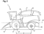
- the first forage harvester 1 is shown in a side view in FIG Figure 1 and the second forage harvester 1 ' in a side view in FIG Figure 2 shown.
- the first forage harvester 1 of the series according to the invention describes a "long forage harvester" whose in Figure 1 Main girders (not shown) are designed in the form of long girders 10 .
- This forage harvester 1 is equipped with crawler tracks 7 on both sides of its front axle 27. These each comprise two opposing main wheels 19 which are spanned by a running belt 20. the Main wheels 19 have the same diameter.
- An auxiliary wheel 21 is arranged between the main wheels 19 and cooperates with a lower section of the running belt 20 .
- the forage harvester 1 is equipped with a conveying element 3 , a chopping element 4 , an acceleration element 18 and an exclamation element 5 .
- These organs together form the working organs of the forage harvester 1 , by means of which the latter is suitable for harvesting and processing crop 2.
- the forage harvester 1 is equipped with a rear wheel 17 on both sides of its rear axle 28 .
- the rear wheels 17 are designed here in the form of customary single wheels.
- the front axle 27 and the rear axle 28 of the forage harvester 1 are located at a center distance 24 measured parallel to a longitudinal axis 29 of the forage harvester 1.
- the crawler tracks 7 and the rear wheels 17 each form propulsion elements of the forage harvester 1 , by means of which the forage harvester 1 stands directly on a ground 16 .
- the propulsion elements enable the forage harvester 1 to move relative to the ground 16 .
- the caterpillars 7 take up more space in the longitudinal direction of the forage harvester 1 than the rear wheels 17.
- a length of a respective crawler drive 7 is significantly greater than the diameter of a rear wheel 17. This ratio applies in principle when comparing caterpillars to single wheels which is simply due to the construction of caterpillars and ultimately also brings the advantages of gentle underground treatment with it.
- a difference area 22 is already shown schematically, which shows a length difference between the forage harvester 1 according to FIG Figure 1 and according to that Figure 2 describes. This is discussed separately below.
- Figure 2 describes a further forage harvester 1 ′ of the series of forage harvesters according to the invention which, in contrast to the forage harvester 1 , is equipped with individual wheels 6 on its front axle 27. Furthermore, the forage harvester 1 'is designed with main beams in the form of short beams 11 , which are shown in FIG Figure 2 are not shown. Regardless of the different shaped main beams, as well as various driving elements on the front axle 27 are the forage harvester 1, 1 'according to the Figures 1 and 2 at least substantially the same.
- the differences are limited to the different lengths of the forage harvester 1, 1 ′, with a center distance 25 between the front axle 27 and the rear axle 28 of the forage harvester 1 ′ falling below the center distance 24 of the forage harvester 1.
- the individual wheels 6 on the forage harvester 1 ′ take up a significantly smaller space in relation to a longitudinal extent in comparison to the crawler tracks 7 parallel to the longitudinal axis 29 of the forage harvester 1 '. Accordingly, it is not necessary to keep a length that would allow crawler tracks 7 to be installed on the forage harvester 1 '.
- the series according to the invention therefore has the particular advantage that the various forage harvesters 1, 1 ' differ from one another only in terms of a very small number of components, namely in particular with regard to the main girders used and those components which, due to a difference in length between the longitudinal girders 10 and the short beams 11 must be designed differently.
- This concerns for example, a housing 23 of a respective forage harvester 1, 1 '.
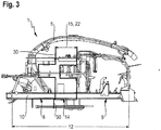
- the various main carriers of the variously designed forage harvesters 1, 1 'of the series according to the invention can be seen particularly well on the basis of the representations according to FIGS Figures 3 and 4th .
- These each show a support frame of a respective forage harvester 1 , 1 '.
- the forage harvester 1 according to the Figures 1 and 3rd is equipped with two main beams in the form of long beams 10 oriented in the longitudinal direction of the forage harvester 1 .
- These longitudinal beams 10 comprise a front section 8, a rear section 9 and a central section 14.
- the working elements of the forage harvester 1 are arranged in the front section 8.
- a drive device that is used in Figure 3 is not shown, is arranged in the rear section 9 .
- the middle section 14 as such has no technical significance, but serves solely to raise a length 12 of the longitudinal beam 10 to such a level that the forage harvester 1 can be equipped with crawler tracks 7 on its front axle 27.
- the middle section 14, which in turn has a length 15 serves to create space for crawler tracks 7.
- the main girders of such a forage harvester 1 ′ of the series according to the invention are formed in the form of short girders 11 .
- These include, comparable to the longitudinal girders 10, a front section 8 and a rear section 9, with the working organs in the front section 8 and in the rear section 9 the working organs in the rear section 9 also being comparable to the longitudinal girders 10 in FIG Figure 4 Not shown drive device of the forage harvester 1 ' are arranged.
- the long support 11 and the short member 10 only through the central portion 14 and the length of which differ 15.
Landscapes
- Life Sciences & Earth Sciences (AREA)
- Environmental Sciences (AREA)
- Engineering & Computer Science (AREA)
- Chemical & Material Sciences (AREA)
- Combustion & Propulsion (AREA)
- Transportation (AREA)
- Mechanical Engineering (AREA)
- Harvesting Machines For Specific Crops (AREA)
- Harvester Elements (AREA)
Claims (4)
- Série d'ensileuses (1, 1'), incluant une pluralité d'ensileuses (1, 1') pour ensiler du produit de récolte (2) se trouvant dans une zone de travail, chacune des ensileuses (1, 1') incluant- au moins un organe de travail en forme d'organe d'amenée (3) pour amener du produit de récolte coupé (2) en direction d'un organe de hachage (4),- au moins un organe de travail en forme d'organe de hachage (4) pour hacher le produit de récolte coupé (2),- au moins un équipement d'entraînement pour entraîner au moins un élément de propulsion, en particulier une roue individuelle (6) ou un train de roulement à chenilles (7) ainsi que les organes de travail, ainsi que- au moins un support principal traversant pour recevoir les organes de travail ainsi que l'équipement d'entraînement,des forces pondérales des organes de travail ou de l'équipement d'entraînement pouvant être dissipées au moins en partie au moyen du support principal,
les organes de travail étant reliés au moins indirectement dans une portion avant (8) et l'équipement d'entraînement au moins indirectement dans une portion arrière (9) du support principal à celui-ci de manière à transmettre les forces,
caractérisée en ce qu'un support principal, conformé en support long (10), d'une ensileuse (1) de la série présente une longueur (12) qui excède une longueur (13) d'un support principal, conformé en support court (11), d'une autre ensileuse (1') de la série, de sorte que le support long (10) et le support court (11) présentent une différence de longueur,
aussi bien le support long (10) que le support court (11) présentant des portions avant (8) et des portions arrière (9) de conception au moins sensiblement identique et
le support long (10) disposant, par rapport au support court (11), d'une portion centrale supplémentaire (14),
toutes les ensileuses (1) de la série qui sont équipées d'un support long (10) étant équipées au moins sur leur essieu avant d'éléments de propulsion en forme de trains de roulement à chenilles (7), et toutes les ensileuses de la série qui sont équipées d'un support court (11) étant équipées sur leur essieu avant d'éléments de propulsion en forme de roues individuelles (6) . - Série selon la revendication 1, caractérisée en ce qu'une longueur (15) de la portion centrale (14) correspond au moins sensiblement, de préférence entièrement, à la différence de longueur entre le support long (10) et le support court (11).
- Série selon la revendication 1 ou 2, caractérisée en ce que les supports longs (10) et les supports courts (11) sont conçus d'une seule pièce.
- Procédé de fabrication d'une série d'ensileuses (1, 1'), incluant les étapes de procédé suivantesa) des organes de travail de l'ensileuse respective (1, 1') sont montés au moins indirectement dans ou sur une portion avant (8) d'un support principal.b) Un équipement d'entraînement d'une ensileuse respective (1, 1') de la série est monté dans une portion arrière (9) du support principal.c) Des éléments de propulsion, en particulier des roues individuelles (6) et/ou des trains de roulement à chenilles (7), au moyen desquels l'ensileuse terminée (1, 1') peut venir en contact direct avec un terrain (16), sont reliés au moins indirectement au support principal, de sorte que des forces agissant sur l'ensileuse (1, 1') sont transférables aux éléments de propulsion et finalement au terrain (16) au moyen du support principal,caractérisé par les étapes de procédé suivantes :d) Au cours de la fabrication au moins d'une ensileuse (1') de la série, un support principal en forme de support court (11) est choisi et utilisé pour la suite du procédé, l'ensileuse (1') ainsi fabriquée étant équipée au moins sur son essieu avant avec des éléments de propulsion en forme de roues individuelles (6) .e) Au cours de la fabrication au moins d'une autre ensileuse (1) de la série, un support principal en forme de support long (10) est choisi est utilisé pour la suite du procédé, l'ensileuse (1) ainsi fabriquées étant équipée au moins sur son essieu avant avec des éléments de propulsion en forme de trains de roulement à chenilles (7),une longueur (12) du support long (10) excédant une longueur (13) du support court (11),
aussi bien le support long (10) que le support court (11) comportant des portions avant (8) et des portions arrière (9) de conception au moins sensiblement identique, et
le support long (10) disposant, par rapport au support court (11), d'une portion centrale supplémentaire (14).
Applications Claiming Priority (1)
| Application Number | Priority Date | Filing Date | Title |
|---|---|---|---|
| DE102017119792.3A DE102017119792A1 (de) | 2017-08-29 | 2017-08-29 | Serie von Feldhäckslern sowie Verfahren zu deren Herstellung |
Publications (2)
| Publication Number | Publication Date |
|---|---|
| EP3449714A1 EP3449714A1 (fr) | 2019-03-06 |
| EP3449714B1 true EP3449714B1 (fr) | 2021-07-21 |
Family
ID=62486474
Family Applications (1)
| Application Number | Title | Priority Date | Filing Date |
|---|---|---|---|
| EP18174855.9A Active EP3449714B1 (fr) | 2017-08-29 | 2018-05-29 | Série de ramasseuses-hacheuses ainsi que leur procédé de fabrication |
Country Status (2)
| Country | Link |
|---|---|
| EP (1) | EP3449714B1 (fr) |
| DE (1) | DE102017119792A1 (fr) |
Families Citing this family (1)
| Publication number | Priority date | Publication date | Assignee | Title |
|---|---|---|---|---|
| DE102019215146A1 (de) | 2019-10-01 | 2021-04-01 | Deere & Company | Feldhäcksler mit einem tragenden Rahmengestell |
Family Cites Families (5)
| Publication number | Priority date | Publication date | Assignee | Title |
|---|---|---|---|---|
| US5290201A (en) * | 1992-06-11 | 1994-03-01 | Tesker Henry L | Combine with mmoveable body and tandem drive wheels |
| DE10150052B4 (de) * | 2001-10-10 | 2005-07-14 | Daimlerchrysler Ag | Fahrgestell für Nutzfahrzeuge |
| DE10327478A1 (de) * | 2003-06-18 | 2005-02-03 | Deere & Company, Moline | Selbstfahrende Erntemaschine |
| DE102008033067A1 (de) | 2008-07-15 | 2010-01-21 | Claas Selbstfahrende Erntemaschinen Gmbh | Landwirtschaftliche Erntemaschine |
| DE102008059467A1 (de) * | 2008-11-28 | 2010-06-10 | Claas Selbstfahrende Erntemaschinen Gmbh | Landwirtschaftliche Zugmaschine |
-
2017
- 2017-08-29 DE DE102017119792.3A patent/DE102017119792A1/de not_active Withdrawn
-
2018
- 2018-05-29 EP EP18174855.9A patent/EP3449714B1/fr active Active
Also Published As
| Publication number | Publication date |
|---|---|
| DE102017119792A1 (de) | 2019-02-28 |
| EP3449714A1 (fr) | 2019-03-06 |
Similar Documents
| Publication | Publication Date | Title |
|---|---|---|
| DE102009009097A1 (de) | Hubbalkenförderer | |
| DD156685A5 (de) | Hydraulikmotor-angetriebenes zweiteiliges gelaendegaengiges fahrzeug | |
| EP1789299B1 (fr) | Vehicule de maintenance | |
| EP2392524A1 (fr) | Dispositif de stockage à travées avec rails de guidage pour un véhicule de rayonnage | |
| EP1942065A1 (fr) | Transporteur de longeron mobile | |
| EP3464019B1 (fr) | Vérification de l'intégrité d'un groupement de véhicules | |
| DE102014004681B4 (de) | Fördermittelzug mit Schlingerunterdrückung | |
| EP3449714B1 (fr) | Série de ramasseuses-hacheuses ainsi que leur procédé de fabrication | |
| DE4322263C5 (de) | Verfahren zur Vorbereitung eines auf einer Bodenfläche fahrenden Arbeitsfahrzeuges mit einem Arbeitsgerät für den Straßenbetrieb und Arbeitsgerät zur Anordnung an einem solchen Arbeitsfahrzeug | |
| DE3151280C2 (de) | Fahrgestellrahmen für Fahrzeuge, insbesondere Omnibusse | |
| DE2047400A1 (de) | Befbrderungseinnchtung | |
| DE202011004025U1 (de) | Fahrwerksrahmen für ein Fahrwerk eines Schienenfahrzeugs | |
| DE102017119796A1 (de) | Feldhäcksler sowie Verfahren zu dessen Umrüstung | |
| EP3398810A1 (fr) | Partie arrière compact de véhicules utilitaires pourvu de partie arrière pouvant être sortie | |
| DE2837191A1 (de) | Fahrgestell fuer anziehungs-magnetschwebefahrzeuge | |
| DE102011112180A1 (de) | Bodenstruktur einer Karosserie eines Personenkraftwagens | |
| EP2639354B1 (fr) | Dameur de pistes pour le traitement des surfaces enneigées | |
| DE102014008086A1 (de) | Stützeinrichtung zum Abstützen einer Antriebseinheit an einer Personenkraftwagenkarosserie | |
| DE102018117214A1 (de) | Schubmaststapler mit einem Überwachungssensor sowie ein Verfahren zum Betrieb eines solchen | |
| DE202009006630U1 (de) | Hubvorrichtung | |
| DE102015215507A1 (de) | Kraftfahrzeugkarosserie mit einer einen Längsträger aufnehmenden, klebetechnisch gefügten Konsole | |
| EP3293097B1 (fr) | Raidisseur de châssis de moissonneuse automotrice | |
| DE1756629A1 (de) | Verladevorrichtung | |
| DE202012004683U1 (de) | Landmaschine | |
| DE102019203758B4 (de) | Strukturbauteil für einen Aufbau eines Fahrzeugs und Fahrzeugaufbau |
Legal Events
| Date | Code | Title | Description |
|---|---|---|---|
| PUAI | Public reference made under article 153(3) epc to a published international application that has entered the european phase |
Free format text: ORIGINAL CODE: 0009012 |
|
| STAA | Information on the status of an ep patent application or granted ep patent |
Free format text: STATUS: THE APPLICATION HAS BEEN PUBLISHED |
|
| AK | Designated contracting states |
Kind code of ref document: A1 Designated state(s): AL AT BE BG CH CY CZ DE DK EE ES FI FR GB GR HR HU IE IS IT LI LT LU LV MC MK MT NL NO PL PT RO RS SE SI SK SM TR |
|
| AX | Request for extension of the european patent |
Extension state: BA ME |
|
| STAA | Information on the status of an ep patent application or granted ep patent |
Free format text: STATUS: REQUEST FOR EXAMINATION WAS MADE |
|
| 17P | Request for examination filed |
Effective date: 20190906 |
|
| RBV | Designated contracting states (corrected) |
Designated state(s): AL AT BE BG CH CY CZ DE DK EE ES FI FR GB GR HR HU IE IS IT LI LT LU LV MC MK MT NL NO PL PT RO RS SE SI SK SM TR |
|
| RIC1 | Information provided on ipc code assigned before grant |
Ipc: A01D 67/00 20060101AFI20201210BHEP Ipc: A01D 43/08 20060101ALI20201210BHEP Ipc: B62D 55/04 20060101ALI20201210BHEP |
|
| GRAP | Despatch of communication of intention to grant a patent |
Free format text: ORIGINAL CODE: EPIDOSNIGR1 |
|
| STAA | Information on the status of an ep patent application or granted ep patent |
Free format text: STATUS: GRANT OF PATENT IS INTENDED |
|
| INTG | Intention to grant announced |
Effective date: 20210205 |
|
| GRAS | Grant fee paid |
Free format text: ORIGINAL CODE: EPIDOSNIGR3 |
|
| GRAA | (expected) grant |
Free format text: ORIGINAL CODE: 0009210 |
|
| STAA | Information on the status of an ep patent application or granted ep patent |
Free format text: STATUS: THE PATENT HAS BEEN GRANTED |
|
| AK | Designated contracting states |
Kind code of ref document: B1 Designated state(s): AL AT BE BG CH CY CZ DE DK EE ES FI FR GB GR HR HU IE IS IT LI LT LU LV MC MK MT NL NO PL PT RO RS SE SI SK SM TR |
|
| REG | Reference to a national code |
Ref country code: GB Ref legal event code: FG4D Free format text: NOT ENGLISH |
|
| REG | Reference to a national code |
Ref country code: CH Ref legal event code: EP |
|
| REG | Reference to a national code |
Ref country code: DE Ref legal event code: R096 Ref document number: 502018006186 Country of ref document: DE |
|
| REG | Reference to a national code |
Ref country code: AT Ref legal event code: REF Ref document number: 1411715 Country of ref document: AT Kind code of ref document: T Effective date: 20210815 |
|
| REG | Reference to a national code |
Ref country code: IE Ref legal event code: FG4D Free format text: LANGUAGE OF EP DOCUMENT: GERMAN |
|
| REG | Reference to a national code |
Ref country code: LT Ref legal event code: MG9D |
|
| REG | Reference to a national code |
Ref country code: NL Ref legal event code: MP Effective date: 20210721 |
|
| PG25 | Lapsed in a contracting state [announced via postgrant information from national office to epo] |
Ref country code: ES Free format text: LAPSE BECAUSE OF FAILURE TO SUBMIT A TRANSLATION OF THE DESCRIPTION OR TO PAY THE FEE WITHIN THE PRESCRIBED TIME-LIMIT Effective date: 20210721 Ref country code: FI Free format text: LAPSE BECAUSE OF FAILURE TO SUBMIT A TRANSLATION OF THE DESCRIPTION OR TO PAY THE FEE WITHIN THE PRESCRIBED TIME-LIMIT Effective date: 20210721 Ref country code: HR Free format text: LAPSE BECAUSE OF FAILURE TO SUBMIT A TRANSLATION OF THE DESCRIPTION OR TO PAY THE FEE WITHIN THE PRESCRIBED TIME-LIMIT Effective date: 20210721 Ref country code: RS Free format text: LAPSE BECAUSE OF FAILURE TO SUBMIT A TRANSLATION OF THE DESCRIPTION OR TO PAY THE FEE WITHIN THE PRESCRIBED TIME-LIMIT Effective date: 20210721 Ref country code: SE Free format text: LAPSE BECAUSE OF FAILURE TO SUBMIT A TRANSLATION OF THE DESCRIPTION OR TO PAY THE FEE WITHIN THE PRESCRIBED TIME-LIMIT Effective date: 20210721 Ref country code: PT Free format text: LAPSE BECAUSE OF FAILURE TO SUBMIT A TRANSLATION OF THE DESCRIPTION OR TO PAY THE FEE WITHIN THE PRESCRIBED TIME-LIMIT Effective date: 20211122 Ref country code: NL Free format text: LAPSE BECAUSE OF FAILURE TO SUBMIT A TRANSLATION OF THE DESCRIPTION OR TO PAY THE FEE WITHIN THE PRESCRIBED TIME-LIMIT Effective date: 20210721 Ref country code: NO Free format text: LAPSE BECAUSE OF FAILURE TO SUBMIT A TRANSLATION OF THE DESCRIPTION OR TO PAY THE FEE WITHIN THE PRESCRIBED TIME-LIMIT Effective date: 20211021 Ref country code: LT Free format text: LAPSE BECAUSE OF FAILURE TO SUBMIT A TRANSLATION OF THE DESCRIPTION OR TO PAY THE FEE WITHIN THE PRESCRIBED TIME-LIMIT Effective date: 20210721 Ref country code: BG Free format text: LAPSE BECAUSE OF FAILURE TO SUBMIT A TRANSLATION OF THE DESCRIPTION OR TO PAY THE FEE WITHIN THE PRESCRIBED TIME-LIMIT Effective date: 20211021 |
|
| PG25 | Lapsed in a contracting state [announced via postgrant information from national office to epo] |
Ref country code: PL Free format text: LAPSE BECAUSE OF FAILURE TO SUBMIT A TRANSLATION OF THE DESCRIPTION OR TO PAY THE FEE WITHIN THE PRESCRIBED TIME-LIMIT Effective date: 20210721 Ref country code: LV Free format text: LAPSE BECAUSE OF FAILURE TO SUBMIT A TRANSLATION OF THE DESCRIPTION OR TO PAY THE FEE WITHIN THE PRESCRIBED TIME-LIMIT Effective date: 20210721 Ref country code: GR Free format text: LAPSE BECAUSE OF FAILURE TO SUBMIT A TRANSLATION OF THE DESCRIPTION OR TO PAY THE FEE WITHIN THE PRESCRIBED TIME-LIMIT Effective date: 20211022 |
|
| REG | Reference to a national code |
Ref country code: DE Ref legal event code: R097 Ref document number: 502018006186 Country of ref document: DE |
|
| PG25 | Lapsed in a contracting state [announced via postgrant information from national office to epo] |
Ref country code: DK Free format text: LAPSE BECAUSE OF FAILURE TO SUBMIT A TRANSLATION OF THE DESCRIPTION OR TO PAY THE FEE WITHIN THE PRESCRIBED TIME-LIMIT Effective date: 20210721 |
|
| PLBE | No opposition filed within time limit |
Free format text: ORIGINAL CODE: 0009261 |
|
| STAA | Information on the status of an ep patent application or granted ep patent |
Free format text: STATUS: NO OPPOSITION FILED WITHIN TIME LIMIT |
|
| PG25 | Lapsed in a contracting state [announced via postgrant information from national office to epo] |
Ref country code: SM Free format text: LAPSE BECAUSE OF FAILURE TO SUBMIT A TRANSLATION OF THE DESCRIPTION OR TO PAY THE FEE WITHIN THE PRESCRIBED TIME-LIMIT Effective date: 20210721 Ref country code: SK Free format text: LAPSE BECAUSE OF FAILURE TO SUBMIT A TRANSLATION OF THE DESCRIPTION OR TO PAY THE FEE WITHIN THE PRESCRIBED TIME-LIMIT Effective date: 20210721 Ref country code: RO Free format text: LAPSE BECAUSE OF FAILURE TO SUBMIT A TRANSLATION OF THE DESCRIPTION OR TO PAY THE FEE WITHIN THE PRESCRIBED TIME-LIMIT Effective date: 20210721 Ref country code: EE Free format text: LAPSE BECAUSE OF FAILURE TO SUBMIT A TRANSLATION OF THE DESCRIPTION OR TO PAY THE FEE WITHIN THE PRESCRIBED TIME-LIMIT Effective date: 20210721 Ref country code: CZ Free format text: LAPSE BECAUSE OF FAILURE TO SUBMIT A TRANSLATION OF THE DESCRIPTION OR TO PAY THE FEE WITHIN THE PRESCRIBED TIME-LIMIT Effective date: 20210721 Ref country code: AL Free format text: LAPSE BECAUSE OF FAILURE TO SUBMIT A TRANSLATION OF THE DESCRIPTION OR TO PAY THE FEE WITHIN THE PRESCRIBED TIME-LIMIT Effective date: 20210721 |
|
| 26N | No opposition filed |
Effective date: 20220422 |
|
| PG25 | Lapsed in a contracting state [announced via postgrant information from national office to epo] |
Ref country code: IT Free format text: LAPSE BECAUSE OF FAILURE TO SUBMIT A TRANSLATION OF THE DESCRIPTION OR TO PAY THE FEE WITHIN THE PRESCRIBED TIME-LIMIT Effective date: 20210721 |
|
| REG | Reference to a national code |
Ref country code: CH Ref legal event code: PL |
|
| GBPC | Gb: european patent ceased through non-payment of renewal fee |
Effective date: 20220529 |
|
| PG25 | Lapsed in a contracting state [announced via postgrant information from national office to epo] |
Ref country code: MC Free format text: LAPSE BECAUSE OF FAILURE TO SUBMIT A TRANSLATION OF THE DESCRIPTION OR TO PAY THE FEE WITHIN THE PRESCRIBED TIME-LIMIT Effective date: 20210721 Ref country code: LU Free format text: LAPSE BECAUSE OF NON-PAYMENT OF DUE FEES Effective date: 20220529 Ref country code: CH Free format text: LAPSE BECAUSE OF NON-PAYMENT OF DUE FEES Effective date: 20220531 Ref country code: LI Free format text: LAPSE BECAUSE OF NON-PAYMENT OF DUE FEES Effective date: 20220531 |
|
| PG25 | Lapsed in a contracting state [announced via postgrant information from national office to epo] |
Ref country code: IE Free format text: LAPSE BECAUSE OF NON-PAYMENT OF DUE FEES Effective date: 20220529 Ref country code: FR Free format text: LAPSE BECAUSE OF NON-PAYMENT OF DUE FEES Effective date: 20220531 |
|
| PG25 | Lapsed in a contracting state [announced via postgrant information from national office to epo] |
Ref country code: GB Free format text: LAPSE BECAUSE OF NON-PAYMENT OF DUE FEES Effective date: 20220529 |
|
| P01 | Opt-out of the competence of the unified patent court (upc) registered |
Effective date: 20230516 |
|
| PG25 | Lapsed in a contracting state [announced via postgrant information from national office to epo] |
Ref country code: HU Free format text: LAPSE BECAUSE OF FAILURE TO SUBMIT A TRANSLATION OF THE DESCRIPTION OR TO PAY THE FEE WITHIN THE PRESCRIBED TIME-LIMIT; INVALID AB INITIO Effective date: 20180529 |
|
| PG25 | Lapsed in a contracting state [announced via postgrant information from national office to epo] |
Ref country code: MK Free format text: LAPSE BECAUSE OF FAILURE TO SUBMIT A TRANSLATION OF THE DESCRIPTION OR TO PAY THE FEE WITHIN THE PRESCRIBED TIME-LIMIT Effective date: 20210721 Ref country code: CY Free format text: LAPSE BECAUSE OF FAILURE TO SUBMIT A TRANSLATION OF THE DESCRIPTION OR TO PAY THE FEE WITHIN THE PRESCRIBED TIME-LIMIT Effective date: 20210721 |
|
| PG25 | Lapsed in a contracting state [announced via postgrant information from national office to epo] |
Ref country code: TR Free format text: LAPSE BECAUSE OF FAILURE TO SUBMIT A TRANSLATION OF THE DESCRIPTION OR TO PAY THE FEE WITHIN THE PRESCRIBED TIME-LIMIT Effective date: 20210721 |
|
| REG | Reference to a national code |
Ref country code: AT Ref legal event code: MM01 Ref document number: 1411715 Country of ref document: AT Kind code of ref document: T Effective date: 20230529 |
|
| PG25 | Lapsed in a contracting state [announced via postgrant information from national office to epo] |
Ref country code: AT Free format text: LAPSE BECAUSE OF NON-PAYMENT OF DUE FEES Effective date: 20230529 |
|
| PG25 | Lapsed in a contracting state [announced via postgrant information from national office to epo] |
Ref country code: AT Free format text: LAPSE BECAUSE OF NON-PAYMENT OF DUE FEES Effective date: 20230529 |
|
| PG25 | Lapsed in a contracting state [announced via postgrant information from national office to epo] |
Ref country code: MT Free format text: LAPSE BECAUSE OF FAILURE TO SUBMIT A TRANSLATION OF THE DESCRIPTION OR TO PAY THE FEE WITHIN THE PRESCRIBED TIME-LIMIT Effective date: 20210721 |
|
| PGFP | Annual fee paid to national office [announced via postgrant information from national office to epo] |
Ref country code: DE Payment date: 20250521 Year of fee payment: 8 |
|
| PGFP | Annual fee paid to national office [announced via postgrant information from national office to epo] |
Ref country code: BE Payment date: 20250521 Year of fee payment: 8 |
|
| PGFP | Annual fee paid to national office [announced via postgrant information from national office to epo] |
Ref country code: AT Payment date: 20260410 Year of fee payment: 5 |