EP3449728A2 - Vorrichtung zum füllen schlauchförmiger hüllen - Google Patents
Vorrichtung zum füllen schlauchförmiger hüllen Download PDFInfo
- Publication number
- EP3449728A2 EP3449728A2 EP18191946.5A EP18191946A EP3449728A2 EP 3449728 A2 EP3449728 A2 EP 3449728A2 EP 18191946 A EP18191946 A EP 18191946A EP 3449728 A2 EP3449728 A2 EP 3449728A2
- Authority
- EP
- European Patent Office
- Prior art keywords
- filling tube
- filling
- support
- support member
- tube
- Prior art date
- Legal status (The legal status is an assumption and is not a legal conclusion. Google has not performed a legal analysis and makes no representation as to the accuracy of the status listed.)
- Granted
Links
Images




Classifications
-
- A—HUMAN NECESSITIES
- A22—BUTCHERING; MEAT TREATMENT; PROCESSING POULTRY OR FISH
- A22C—PROCESSING MEAT, POULTRY, OR FISH
- A22C11/00—Sausage making ; Apparatus for handling or conveying sausage products during manufacture
- A22C11/02—Sausage filling or stuffing machines
- A22C11/0227—Supplying casings to the stuffing device
-
- A—HUMAN NECESSITIES
- A22—BUTCHERING; MEAT TREATMENT; PROCESSING POULTRY OR FISH
- A22C—PROCESSING MEAT, POULTRY, OR FISH
- A22C11/00—Sausage making ; Apparatus for handling or conveying sausage products during manufacture
- A22C11/02—Sausage filling or stuffing machines
- A22C11/0209—Stuffing horn assembly
- A22C11/0218—Stuffing horn assembly with multiple interchangeable stuffing horns, e.g. magazine arrangements
-
- A—HUMAN NECESSITIES
- A22—BUTCHERING; MEAT TREATMENT; PROCESSING POULTRY OR FISH
- A22C—PROCESSING MEAT, POULTRY, OR FISH
- A22C11/00—Sausage making ; Apparatus for handling or conveying sausage products during manufacture
- A22C11/02—Sausage filling or stuffing machines
- A22C11/0245—Controlling devices
- A22C11/0263—Braking means
Definitions
- the present invention relates to a device for filling tubular casings, with a pasty mass, in particular of sausage meat sausage meat, with at least one filling tube, onto which a shell that can be filled with a mass can be drawn up, a receiving part receiving a first end of the filling tube, a gut brake unit, which is assigned to the opposite second, open end and can be brought into operative connection with the shell pulled over the filling tube, and a support means for the filling tube arranged on the receiving part.
- the invention further relates to a support device for at least one filling tube of a device for filling tubular casings with pasty mass, in particular of intestinal caterpillars with sausage meat.
- the invention also relates to a filling machine for producing sausages from pasty mass, in particular from sausage meat, with a hopper for receiving the pasty mass, a feed pump for conveying the pasty mass and a device for filling tubular casings with pasty mass.
- a pasty mass such as sausage meat or the like
- the filling of the pasty mass in the tubular casing can be continuous or in portions, so that the pasty mass is continuously or intermittently entered into the tubular casing.
- a tubular casing can be an artificial intestine or a natural gut.
- a pasty mass is understood as meaning a foodstuff which is capable of flowing and which can be transported via a tubular conduit.
- a pasty mass for example, in addition to a meat or sausage mass and a dough mass to understand.
- the already filled casing is divided off or turned off at predetermined intervals, so that separation points are generated between the respectively filled casing sections.
- the filled shell thus has separate strand sections, which in particular have the same weight and preferably an equal length.
- the mutually subdivided strand sections are then usually separated from each other, whereby isolated strand sections are formed, which are referred to as sausages and fed, for example, a packaging machine for further processing.
- the tubular casing is in particular gathered, so that the shirred casing, which is primarily an artificial gut, hereinafter referred to as intestinal caterpillar, shorter than the filling tube is.
- the shirred casings can have different diameters, also called calibers.
- the empty filling tube For loading a filling tube with a new tubular sheath, which is done using a gut gripping device or a gut loading unit, the empty filling tube is to be pivoted to a loading position. A stuffed with a shirred casing filling tube is in turn to move to a filling position. When pivoting the empty as well as equipped stuffing tube this can easily get into vibration, so that the loading of a new shirred casing is made difficult by a intestinal gripping device or intestinal loading unit or in contacting the already stocked casing with a gut brake unit.
- Such a Darmbremsaku keeps the envelope when filling with the pasty mass taut, which is done by the fact that the filling tube with the shell with its free end enters the intestinal brake unit. If the free end of the filling tube is not centric to the intestinal brake unit, the front end of the sheath may bend or damage the filling tubes.
- a device for filling tubular casings of the aforementioned type which has a support means for the filling tube arranged on the receiving part, which is coupled to a gutter ring movable along the filling tube and which is in contact with the open end of the shirred casing.
- known support means causes only a sufficient support effect when the Darmmit shakingring is located near the open end of the filling tube.
- the filling tube is not equipped with a shell.
- the stuffing tube is fitted with a shirred casing, also called a gut plug, the gutter ring is in a position close to the stuffing tube receiving part.
- the open end of the filling tube in the assembled state is almost free-swinging.
- a gut brake unit When contacting the free populated end of the filling tube with a gut brake unit, there may be an unwanted contact between the two components due to the non-alignment of intestinal brake unit and filling tube or due to the kinking of the shirred casing.
- the present invention seeks to provide an apparatus for filling tubular sheaths of the aforementioned type and a support device for a filling tube and a filling machine for the production of sausages to the effect, regardless of whether the filling tube is equipped or unpopulated, the Supporting effect on the filling tube is improved, so that increased process reliability is achieved during operation of the filling device.
- the invention solves its underlying object in a device for filling tubular sheaths of the aforementioned type by the features of the subject matter of claim 1.
- the support means at least one variable distance from the receiving part variable support part, which is adapted to, with a shirred casing to be brought into contact on the filling tube for receiving transverse forces.
- the invention is based on the finding that, with the aid of a supporting part arranged on the supporting device, which is variable at a distance from the receiving part and which comes into contact with a sheath which is shirred on the filling tube, in particular its outer circumference can be brought, the filling tube is supported laterally at the free end during its pivoting movement when the filling tube is equipped with a shirred casing and thus acts on the filling tube an additional load.
- the bearing against the outer side of the sleeve support member is variable in the distance to the receiving part such that when the stuffed with a shirred casing filling tube is brought at its free end with the Darmbremsö in contact, the support member by contacting with the Darmbremsritt along the filling tube is movable.
- the contacting the Darmbremsritt with the filling tube is effected by a relative movement of the two components to each other, wherein at least one of the components is moved.
- the support member at the same time also has the function of a centering device.
- the support member is preferably associated with the free end and adapted to align the open or free end of the filled filling tube to the then to be brought into contact with the filling tube Darmbremsö.
- the filling tube is according to a preferred embodiment rotatable about its longitudinal axis and drivable and thus rotatably received on the Abwindkopf. In another embodiment, the filling tube is stationary.
- the support member has at least one support surface at least partially surrounding the shell on the fill tube.
- a lateral deflection of the filling tube is counteracted.
- the lateral deflection is not completely prevented by the support part according to the invention, but limited insofar that the free end of the filling tube can only be deflected laterally to the extent that an exclusively elastic deformation occurs at this.
- the wall of the shirred casing is arranged between the support surface, which preferably rests virtually gap-free on the outside of the shirred casing, and the outside of the filling tube.
- the support part has a support surface which can be brought into contact with the outer circumference of a guttering ring movable along the filling tube.
- the support member is thus adapted to be brought into contact with a gutter receiving ring approximated to the free end of the filling tube for receiving transverse forces.
- the stuffing tube is laterally supported, in particular, when the shirred casing has been pulled off the stuffing tube after the casing has been filled.
- the guttering ring which can be moved along the filling tube moves into a section of the region of the supporting part which has a supporting surface.
- the support member at the free end of the filling tube moves over about a quarter or fifth of the length of the filling tube.
- the support surfaces each form a receiving space, preferably a cylindrical receiving space for the shirred casing and along the filling tube movable Darmmitddlingring.
- the support member thus preferably has both the shell and the Darmmitddlingring circumferentially surrounding supporting surfaces, whereby a deflection of the filling tube in any lateral direction, preferably perpendicular to the longitudinal axis of the filling tube can be safely accommodated.
- a cylindrical receiving space for the shirred casing and a cylindrical receiving space for the Darmmit shakingring formed on the support member which preferably have different diameters.
- the receiving spaces have an axial offset from each other, wherein the longitudinal axes of the receiving spaces are arranged coaxially.
- the support member is a support sleeve with one or more support surfaces for the shirred casing and / or the Darmmitddlingring.
- the support member With the configuration of the support member as a support sleeve a structurally simple way for the permanent lateral support of the filling tube is effected in particular during the pivoting of the empty or filled filling tube to the filling device.
- the support sleeve surrounds the filling tube regardless of whether the filling tube is equipped with a shirred casing or whether the filling tube, due to an immediately before completed filling process, is empty.
- the support sleeve is designed and arranged to hold the filler tube over the shell portion raised thereon, or to hold it by a gutter ring movable along the fill tube in a correspondingly rectilinear orientation to its end preferably rotatably received on the receiving member.
- this is Support member formed along the filling tube movable.
- the support member does not have its own drive for moving the support member along the fill tube.
- the support member has a centering portion for receiving in the receiving space in sections Darmmitddlingring. About the centering is avoided in particular when retracting the Darmmit Vietnameseringes in the receiving space designed as a support sleeve support member at the end of the filling that a not exactly aligned to the support sleeve filling tube along the filling tube moving Darmmitddlingring moves against an end face of the supporting sleeve formed as a support member.
- the centering portion has a tapered in the direction of the free end of the filling tube entrance section, which then merges into the receiving space with a constant diameter for the Darmmitddlingring.
- the gutter engaging ring has a contact surface corresponding to the centering portion on the support member, which is preferably also conical or cone-shaped.
- the support part has a guide carriage, which is movable along a guide of the support device running parallel to the longitudinal axis of the filling tube.
- the support member can preferably be guided guided along the filling tube, wherein the guide carriage along the guide of the support means is preferably received slidingly movable.
- the distance between the support member to the end of the filling tube is thus variable or adjustable in a simple manner, and at the same time ensures the guide carriage exact alignment of the support member to the longitudinal axis of the preferably rotatably and drivable held on the receiving part of the device filling tube.
- the guide carriage and the guide carriage receiving guide of the support means are preferably mounted on a sliding or roller bearings each other.
- the guide takes the guide carriage together with the support member preferably rotatably on.
- the position of the displaceably received support member is adjusted in response to, for example, a free-end engageable intestine brake unit or an intestinal loading unit.
- a driver is arranged on the support member, by means of which the support member is selectively movable along the filling tube. Due to the fact that along the filling tube movable support member does not have its own drive for an adjustment in the longitudinal direction, the movement of the support member is effected by other, driven component of the device.
- the driver can in particular a on the support member or on the guide carriage of the Support member be formed material projection, for example, engages with a stop member on a support member moving component of the device according to the invention or corresponds with this.
- the driver for a movement of the support member along the filling tube with a portion of the intestinal brake unit or a intestinal loading unit can be coupled.
- the component of the filling device according to the invention which can be brought into contact or operatively connected to the filling tube preferably has a stop part corresponding to the carrier, which moves the supporting part into a position required correspondingly to the device.
- the driver on the support member is formed such that the support member in both directions along the filling tube on the support means by at least one of the components, namely the intestinal brake unit or the intestinal loading unit is designed to be movable.
- the movement or adjustment of the support member is thus carried out in each case specifically on the own drive device having component of the filling device, namely the intestinal brake unit or the intestinal loading unit, so that the support member according to the invention does not require its own drive.
- the intestinal loading unit and the intestinal brake unit are designed to be stationary. The axial movement of the filling tube and the driving of the support member moving carrier take place via the trained as a turning head receiving part which is moved in the longitudinal direction of the filling tubes.
- the support member is adapted to be moved before or during the winding of the tubular casing on the filling tube, preferably by means of a gut-loading unit, in the direction of the receiving part.
- the intestinal loading unit has for this purpose an actuator which acts against the driver on the support member and in particular shifts a guide carriage of the support member along the guide on the support means in a predetermined angular orientation in the longitudinal direction of the guide on the support means.
- the support member is disposed during filling of the tubular casing and / or during pivoting of the filling tube in the region of the open end of the filling tube.
- the support member thus supports, in particular, always the open end of the filling tube and the front end of a trained already on the filling tube intestinal bead, if Transverse forces or forces act laterally on the filling tube, for example during pivoting of the filling tube over the receiving part, or when contacting the filling tube with the Darmbremsaku and the subsequent filling of the tubular casing.
- the filling tube When the free end of the filling tube is brought into contact with the intestinal brake unit, the filling tube is supported on the supporting surface of the supporting part via the shirred casing or intestinal bead raised on the filling tube.
- the empty filling tube is supported relative to the support member during the pivoting of the filling tube by means of the guttering ring approximated to the free end of the filling tube.
- the Darmmit shakingring fills instead of the then completely withdrawn from the filling tube shell the free space between the support surface on the support member and the filling tube.
- the support part is associated with a return device, which is adapted to move the support member after pulling the sheath on the filling tube in a predetermined position along the filling tube.
- a return device which is adapted to move the support member after pulling the sheath on the filling tube in a predetermined position along the filling tube.
- an automatic return movement of the support member is effected in a predetermined position on the filling tube.
- the support member is preferably moved near the second, free end of the filling tube. From this position, the support member is moved out of its front position by the intestinal brake unit or the intestinal loading unit, if necessary.
- the support member is moved over the gutter ring in the direction of the free end of the filling tube.
- the resetter is in a preferred embodiment of the invention, a coupled to the guide and the guide carriage of the support member spring element, which allows a structurally simple design for the formation of a restorer. As the support member moves out of a neutral position resulting from the reset, a restoring force is generated on the spring member which becomes greater the farther the support member is moved out of its neutral position.
- the support member can be equipped with an adapted to the caliber of the sleeve to be processed in the inner diameter insert. It is ensured that the support surface for the mounted on the filling tube shell can be easily adjusted without having to replace the entire support member on the device.
- the replaceable on the support member insert is sleeve-like and extends in particular over a portion along the inner diameter of a preferably as a support sleeve trained support part.
- the sleeve-like insert on its outer periphery on radially outward projections. These engage, for example, in formed on the inside of the support member recesses, whereby a locking takes place in the axial direction and in the circumferential direction of the support member.
- each guide has one or more fixedly arranged on the receiving part guide struts.
- the guide carriage of the support member is guided.
- two guide struts are provided as a guide for the guide carriage of the support member, whereby an automatic alignment of the guide carriage arranged on the support member is given based on its radial orientation to the filling tube on the filling device.
- the guide strut or the guide struts have a cylindrical cross-section, wherein the at least one guide strut extends preferably over at least two thirds of the total length of the filling tube, preferably over more than three quarters of the total length of the filling tube, so that the support member almost every section of the respective Can support the filling tube.
- a plurality of filling tubes are arranged on the receiving part, wherein each filling tube is mounted on a spaced apart from the receiving part and thus to the mounted end of the filling tube supporting part.
- a plurality of filling tubes which are preferably rotatable and drivable about their longitudinal axis, an improved filling process with respect to the economy on the inventively designed filling device is achieved.
- the filling process of the shell mounted thereon can be implemented on the respective other filling tube.
- the filling device on the receiving part on two or three filling tubes.
- the second preferably designed as a floating bearing point for the filling tubes that none of the receiving part drivable mounted filling tubes when mounting a new tubular casing or when bringing into contact with the intestinal brake unit is bent transversely to the longitudinal direction.
- the filling tubes stabilized with the support device are held, for example, positionally accurate to the intestinal gripping device or the intestinal brake unit, which simplifies the pushing on or pulling on of a new tubular casing and / or bringing the open end of a respective filling tube into contact with the casing brake unit.
- the receiving part on a pivot plate which is movably held on the device and on which the filling tube is preferably arranged horizontally projecting.
- the pivot plate has a plate plane on which the filling tube preferably projects vertically.
- the receiving part is designed as a twisting head, which has an axis of rotation which is aligned in each case parallel to the axis of rotation of the filling tube.
- a structurally easy to implement pivotal movement of the filling tube is achieved at the filling device.
- a simple rotational movement of the Abfoxkopfes about the axis of rotation a respectively new to be filled stuffing tube can be moved from its filling position.
- the filling position is the position of the filling tube on the filling device, in which the filling tube is brought into contact with the intestinal brake unit during the filling process.
- the filling tube is transferred to a position in which there is sufficient freedom of movement for the filling tube with the tubular shell-stocking intestinal loading unit.
- the swivel plate of the Abfoxkopfes preferably has a circular shape, arranged on the at least one filling tube, preferably two or more filling tubes evenly spaced and also arranged symmetrically to the axis of rotation of the pivot plate.
- rotatable and drivable filling tubes thus a uniform distribution of forces is effected.
- the pivoting movement can be performed at a high speed, without the risk that the filling tubes are vibrated so that permanent deformation of the filling tubes arise and / or bend the shirred tubular casing.
- the support means preferably has a coaxial with the axis of rotation of the pivot plate arranged central strut on which the guide struts of a respective guide are arranged to extend parallel.
- a central strut and the parallel extending guide struts is a solid, frame-like structure of the support means for the arranged on the receiving part of the device filling tubes created, which also has a high structural strength. This causes an exact alignment of the filling tubes to the receiving part.
- the guide struts of a respective guide are aligned parallel to the central strut of the support means, whereby the movably received supporting parts precisely guided and an exact centering of the otherwise only one end rotatably and drivably received filling tubes is possible.
- the free ends of the guide struts are coupled via a connecting flange with the central strut.
- a partially along the central strut movable guide part of the intestinal brake unit is arranged.
- a coupling between the support means and the intestinal brake unit is created, whereby a preferred exact alignment of the intestinal brake unit is effected to the support means of the filling device according to the invention.
- the guide member serves in a possible embodiment at the same time as a return for the support member, since the guide member of the Darnbremshim is preferably coupled to the driver of a respective support member.
- a support device for at least one filling tube of a device for filling tubular casings with pasty mass, in particular of intestinal caterpillars with sausage meat which is characterized by a support member for the filling tube, which is variable in the longitudinal direction of the filling tube at a distance a receiving part rotatably receiving the filling tube and being adapted to be brought into contact with a shirred casing on the filling tube for absorbing transverse forces, and wherein the supporting device is for use on a device for filling tubular casings according to one of the preferred embodiments described above is set up.
- a second bearing point is preferably formed, which in particular supports the free end of the filling tube when the filling tube is pivoted on the receiving part, so that lateral forces act on the filling tube or the second , Free end of the filling tube, for example, with a gut-loading unit or a gut brake unit is brought into contact.
- pivoting in particular forces are absorbed and limited the deflection of the filling tube transversely to its longitudinal axis.
- the supporting part of the support device assumes an alignment or centering function on preferably the free end of the filling tube.
- the support device is preferably rigidly receivable on a receiving part, which is designed as a swiveling plate, of a filling device as described above.
- the invention further relates to a filling machine for producing sausages from pasty mass, in particular from sausage meat, with at least one hopper for receiving the pasty mass, with a feed pump for conveying the pasty mass and a device for filling tubular casings with a pasty mass , in particular sausage meat sausage meat patties according to any one of the above-described preferred embodiments, and preferably with at least one gut loading unit for intestinal caterpillars with two gripping elements held movable relative to each other.
- the support sleeve prevents kinking of the drawn on the tube tubular, preferably shirred casing when pivoting the filling tube.
- the risk of bending of the filling tubes is avoided transversely to the longitudinal axis during the Auf ists the tubular shells or during contacting with a Darmbremsech at the open end of a respective filling tube with the preferably along the filling tube displaceably trained support member.
- the support member hinders the swinging of the stuffing tube during and after pivoting.
- the gripping elements receiving the shirred casings are preferably rotatably mounted on at least one lever element or are received in mutually variable height by means of a lifting linkage parallel and linear in height.
- Advantageous embodiments of the filling machine can be found in the above embodiments of the filling device according to the invention and its preferred embodiments.
- the Fig. 1 and 2 show a machine 100 for filling tubular casings, in particular artificial or natural casings, in connection with an attachment 110 to which a filling device 2 and a gut loading unit 112 are arranged.
- the machine 100 further includes a hopper 102 and an extrusion head 104, which is coupled via a dispensing tube 106 with a turret 4 of the filling device 2 media-conducting.
- the intestinal loading unit 112 comprises a sheath magazine 114 for a plurality of shingled tubular sheaths 6, in particular shirred artificial casings, and a sheath gripping device 116.
- a conveyor 118 with two spaced apart in a horizontal plane conveying elements 120 for the of the filling device 2 sausages 122 produced arranged.
- Fig. 3 shows the attachment 110 with its filling device 2 for filling the tubular sheaths 6 by means of the extruded head 104 in the direction of the Abcardkopfes 4 of the filling promoted pasty mass.
- the turret 4 has in the embodiment shown a rotatably received receiving part 8 for two, arranged on the receiving part 8 filling tubes 10, 10 '.
- the rotatable receiving part 8 is formed with an axis of rotation extending in the horizontal plane.
- On the receiving part 8, a support means 12 is arranged for the filling tubes.
- the support means 12 comprises for each filling tube 10, 10 'at a distance x (as in Figs. 4 and 10 illustrates) to the receiving part 8 variably recorded support member 14, 14 '.
- the support members 14, 14 ' are in particular to the free end 16, 16' ( Figure 5 ) of a respective filling tube 10, 10 'held adjustable. With the aid of the support parts 14, 14 ', the ends 16, 16' of the filling tubes 10, 10 'are held or centered essentially to their axis of rotation. This can be applied to the filling tubes lateral forces, Also referred to as transverse forces, 8 are securely received when pivoting the receiving part about its axis of rotation. Also support the support members 14, 14 ', which are formed in one embodiment of the invention as a support sleeve, the front end of a wound on the filling tube shell 6 during pivoting, whereby the kinking of the sheath during the pivoting operation of the filling tubes is avoided.
- the 4 and 5 11 shows an enlarged partial view of the filling device 2 and the supporting device 12 arranged on the filling device.
- the filling tube 10 'arranged in the upper position is assigned the intestinal loading unit 112 with its envelope gripping device 116.
- the envelope gripping device 116 comprises two gripping elements 124, 124 'which are held relative to one another and with which a tubular envelope 6 is taken over by the envelope magazine 114 (not shown in more detail).
- the sheath 6 is at least held between the gripping elements 124, 124 '.
- the filling tube 10 arranged in the filling position is assigned a casing brake unit 126, also referred to as a casing brake unit, which in particular causes the casing 6 mounted on the filling pipe 10 to be held taut during its filling and the casing 6 to be pulled off from the filling pipe 10 in a controlled manner.
- a casing brake unit 126 also referred to as a casing brake unit, which in particular causes the casing 6 mounted on the filling pipe 10 to be held taut during its filling and the casing 6 to be pulled off from the filling pipe 10 in a controlled manner.
- Fig. 5 and the in Fig. 6 shown detail Fig. 5 show the moment shortly before the mounting of a sleeve 6 accommodated on the envelope gripping device 116 onto the filling tube 10 '.
- the filling tube 10 ' before the sheath is pushed onto the filling tube, centered by means of Darmmit Spotifyringes 18 via a support surface 20 on the support member 14'.
- the support surface 20 forms a cylindrical receiving space 22 on the support member 14 'from.
- the open end of the sheath 6 can be brought into contact with the gutter receiving ring 18 which can be moved along the filling tube 10 ', with the guttering ring 18 being displaced by means of the sheath 6 in the direction of the end of the stuffing tube 10' movably arranged on the receiving part 8.
- the intestinal loading unit 112 comprises a slide 128, which engages between the gripping elements 124, 124 '. About this the sheath 6 and also the Darmmit shakingring in the direction of the receiving part 8 rotatably arranged end of the filling tube 10 'is pushed.
- an adjusting device 24 for the support parts 14, 14 ' is arranged on the casing brake unit 126, which influences the position of the support parts 14, 14' along the filling pipes 10, 10 '.
- the actuating device 24 coupled to the casing brake unit comprises an actuator 26 for adjusting the support part in the direction of the receiving part 8 for the filling pipes 10, 10 '.
- the adjusting device 24 has a return plate 28 which is adapted to move the support sleeve 12 'at the filling tube 10' located in the upper loading position in the direction of the open end 16 'of the filling tube when the sleeve is wound up is.
- the support members 14, 14 'each have a driver 29 which is coupled to a portion of the intestinal brake unit 126 or the intestinal loading unit 112.
- Intestinal braking unit 126 and / or intestinal loading unit have for this purpose an adjusting device which is adapted to the support parts 14, 14 'during the Auf convinceds a tubular casing on a respective filling tube 10, 10' and / or during the contacting with the intestinal brake unit 126 in Direction of the receiving part 8 to move.
- the adjusting device is arranged in a further embodiment, to move the support members 14, 14 'after pulling the sheath on the filling tube 10' in the loading position in the direction of the open end of a respective filling tube.
- the supporting parts 14, 14 'accommodated movably along the support device 12 each have a guide carriage 30, 30', which are movable along a guide 32, 32 ', aligned parallel to the longitudinal axis of the filling tube, with the guide struts 34, 34'.
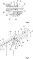
- Fig. 7 and 8th 3 shows the loading step in which the slider 128 of the intestinal loading unit 112 has pushed the sheath 6 onto the filling tube 10 'in the upper position on the filling device 2.
- the distance between the gripping elements 124, 124 ' is to be selected on the envelope gripping device 116 so that the outer circumference of the sheath 6 is not clamped, but the shell by means of the slider 128 between the gripping elements can be moved.
- Darmmit Spotifyringes 18 now takes over the shell 6, the alignment or centering function of the filling tube 10 'to the support sleeve 14', wherein the sheath 6 with a support surface 20 '(FIG. Fig.
- Fig. 7 and 8th illustrate the filling of the sheath 6 on the filling tube 10 in the lower filling position, wherein the Darmmit shakingring 18 moves on the filling tube 10 in the direction of the front end 16
- the filling tube 10 is now aligned in the lower position over the moving to the end 16 of the filling tube 10 Darmmit shakingring 18 to the support member 14.
- the slider 128 remains during the movement of the support member 14 'in the end of the filling tube 10' approximate position.
- the return plate 28 engages the guide carriage 30' for the support member 14 '.
- the support member 14 ' which is equipped with an adapted to the diameter of the over the filling tube 10' sheath 6 6 insert 36 overlaps the front end of the shell 6 by the method in its forward position almost completely.
- each support member 14, 14 ' is slidably received with its guide carriage 30, 30' along the guide strut 34, 34 'of the guide 32, 32'.
- the support means 12 has a coaxial with the axis of rotation of the receiving part 8 arranged central strut 40, to which the guide struts 34, 34 'of a respective guide are arranged to extend in parallel.
- the guide struts 34, 34 'and the central strut 40, the rotationally fixed to the receiving part 8 of the Abfoxkopfes 4 are respectively fixedly coupled to each other at the end via a connecting flange 42, about which the support means 12 forms a solid frame structure.
- Fig. 11 detail shown Fig. 10 can be seen, in the central strut 40 with the guide carriage 30, 30 'corresponding recesses 44, 44' are provided, in which portions of the guide carriage are movably received.
- the arranged in a preferred embodiment of the Darmbremsaku 126 retractor 28 engages over a formed in the connecting flange 42 opening 46 in the central strut 40 and cooperates with the driver 29 of a respective guide carriage 30, 30 'of a support member 14, 14' together, in the upper loading position of the filling device is.
- the return actuator 28 has a spring-loaded latching element 48, which can be brought into operative connection with the driver 29 on the guide carriage 30, 30 'and engages behind regions of the guide carriage.
- the receiving part 8 of the turning head 4 is moved as shown in FIG Fig. 9 indicated movement arrow turned 180 degrees or pivoted.
- the filling tube 10 'now equipped with the casing is moved into the filling position and the "empty" filling tube 10 is moved into the upper loading position.
- the then in the loading position filling tube 10 is now, as at Fig. 4 starting, again equipped with a new shell 6.
- the filling tube 10 'located in the lower position, in particular its front end 16', is brought into contact with the casing brake unit 126, the casing brake unit being pushed onto the end 16 'of the filling tube or onto the end of the casing 6.
- the actuator 26 arranged on the intestinal brake unit 126 moves the support part 14 'into its rearward position in the direction of the receiving part 8 Fig. 4 shown initial state produced and a new filling and Be Publishedvorgang to the filling device 2 can start.
Landscapes
- Engineering & Computer Science (AREA)
- Life Sciences & Earth Sciences (AREA)
- Wood Science & Technology (AREA)
- Zoology (AREA)
- Food Science & Technology (AREA)
- Mechanical Engineering (AREA)
- Processing Of Meat And Fish (AREA)
Abstract
Description
- Die vorliegende Erfindung bezieht sich auf eine Vorrichtung zum Füllen von schlauchförmigen Hüllen, mit einer pastösen Masse, insbesondere von Darmraupen mit Wurstbrät, mit zumindest einem Füllrohr, auf das eine mit einer Masse befüllbare Hülle aufziehbar ist, einem ein erstes Ende des Füllrohres aufnehmenden Aufnahmeteil, einer Darmbremseinheit, welche dem gegenüberliegenden zweiten, offenen Ende zugeordnet und mit der über das Füllrohr gezogenen Hülle in Wirkverbindung bringbar ist, und einer am Aufnahmeteil angeordneten Stützeinrichtung für das Füllrohr. Die Erfindung betrifft des Weiteren eine Stützeinrichtung für zumindest ein Füllrohr einer Vorrichtung zum Füllen von schlauchförmigen Hüllen mit pastöser Masse, insbesondere von Darmraupen mit Wurstbrät. Ferner betrifft die Erfindung auch eine Füllmaschine zum Herstellen von Würsten aus pastöser Masse, insbesondere aus Wurstbrät, mit einem Fülltrichter zum Aufnehmen der pastösen Masse, einer Förderpumpe zum Fördern der pastösen Masse und einer Vorrichtung zum Füllen von schlauchförmigen Hüllen mit pastöser Masse.
- Vorrichtungen zum Füllen von schlauchförmigen Hüllen werden üblicherweise an Füllmaschinen zum Herstellen von Wurststrängen verwendet, mittels derer eine pastöse Masse, wie Wurstbrät oder dergleichen, in schlauchförmige Hüllen eingegeben oder eingefüllt wird. Das Einfüllen der pastösen Masse in die schlauchförmige Hülle kann kontinuierlich oder portionsweise erfolgen, sodass die pastöse Masse fortwährend oder taktweise in die schlauchförmige Hülle eingegeben wird. Als schlauchförmige Hülle kann ein Kunstdarm oder ein Naturdarm verwendet werden. Unter einer pastösen Masse ist vorliegend eine Lebensmittelmasse zu verstehen, die fließfähig ist und über eine rohrförmige Leitung transportiert werden kann. Als pastöse Masse ist z.B. neben einer Fleisch- oder Wurstmasse auch eine Teigmasse zu verstehen.
- Während des Füllvorganges der schlauchförmigen Hülle wird die bereits befüllte Hülle in vorbestimmten Abständen abgeteilt bzw. abgedreht, sodass zwischen den jeweils befüllten Hüllenabschnitten Trennstellen generiert sind. Die befüllte Hülle weist somit voneinander separierte Strangabschnitte auf, welche insbesondere ein gleiches Gewicht und bevorzugt eine gleiche Länge haben. Die voneinander unterteilten Strangabschnitte werden anschließend üblicherweise voneinander getrennt, wodurch vereinzelte Strangabschnitte entstehen, die als Würste bezeichnet werden und beispielsweise einer Verpackungsmaschine zur Weiterverarbeitung zugeführt werden.
- Um die schlauchförmige Hülle befüllen zu können, ist diese zuvor auf einem Füllrohr einer Füllvorrichtung aufzuziehen, wobei die schlauchförmige Hülle insbesondere gerafft ist, sodass die geraffte Hülle, bei der es sich vornehmlich um einen Kunstdarm handelt, im folgenden auch als Darmraupe bezeichnet, kürzer als das Füllrohr ist. Die gerafften Hüllen können unterschiedliche Durchmesser, auch Kaliber genannt, haben. Mit Hilfe einer Fördereinrichtung, welche insbesondere der Füllvorrichtung vorgeschaltet ist, wird die pastöse Masse durch das Füllrohr in die endseitig geschlossene schlauchförmige Hülle gepresst. Durch das Einleiten der Masse in die Hülle wird diese allmählich vom offenen Ende des Füllrohres heruntergezogen und dann das Füllrohr, welches beispielsweise dreh- und antreibbar ist, mitsamt der noch darauf befindlichen Hülle um seine Längsachse zum Erzeugen der Abdrehstelle gedreht.
- Zum Bestücken eines Füllrohres mit einer neuen schlauchförmigen Hülle, was unter Verwendung einer Darmgreifvorrichtung bzw. einer Darm-Beladeeinheit erfolgt, ist das leere Füllrohr in eine Beladeposition zu verschwenken. Ein mit einer gerafften Hülle bestücktes Füllrohr ist wiederum in eine Befüllposition zu bewegen. Beim Verschwenken des leeren wie auch bestückten Füllrohres kann dieses leicht in Schwingung geraten, sodass das Bestücken mit einer neuen gerafften Hülle durch eine Darmgreifvorrichtung bzw. Darm-Beladeeinheit oder ein in Kontaktbringen der bereits bestückten Hülle mit einer Darmbremseinheit erschwert ist.
- Eine solche Darmbremseinheit hält die Hülle beim Befüllen mit der pastösen Masse straff, was dadurch erfolgt, dass das Füllrohr mit der Hülle mit seinem freien Ende in die Darmbremseinheit einfährt. Ist das freie Ende des Füllrohres dann nicht zentrisch zur Darmbremseinheit, kann das vordere Ende der Hülle abknicken oder es zu Schäden an den Füllrohren kommen.
- Aus
DE 20 2013 010 285 ist eine Vorrichtung zum Füllen schlauchförmiger Hüllen vorbezeichneter Gattung bekannt, welche eine am Aufnahmeteil angeordnete Stützeinrichtung für das Füllrohr aufweist, welche mit einem entlang des Füllrohres verfahrbaren Darmmitnahmering gekoppelt ist, der mit dem offenen Ende der gerafften Hülle in Kontakt steht. Die ausDE 20 2013 010 285 bekannte Stützeinrichtung bewirkt jedoch nur eine ausreichende Stützwirkung, wenn der Darmmitnahmering nahe dem offenen Ende des Füllrohres angeordnet ist. Das ist jedoch nur der Fall, wenn das Füllrohr nicht mit einer Hülle bestückt ist. Ist das Füllrohr jedoch mit einer gerafften Hülle, auch bezeichnet als Darmraupe, bestückt, ist der Darmmitnahmering in einer Position nahe dem Aufnahmeteil für das Füllrohr. Dadurch ist das offene Ende des Füllrohrs in bestücktem Zustand nahezu freischwingend. Beim Inkontaktbringen des freien bestückten Endes des Füllrohres mit einer Darmbremseinheit kann es aufgrund des Nichtfluchtens von Darmbremseinheit und Füllrohr oder aufgrund des Abknickens der gerafften Hülle zu einem ungewollten Kontakt beider Bauteile kommen. - Vor diesem Hintergrund liegt der vorliegenden Erfindung die Aufgabe zugrunde, eine Vorrichtung zum Füllen schlauchförmiger Hüllen der vorbezeichneten Art sowie eine Stützeinrichtung für ein Füllrohr und eine Füllmaschine zum Herstellen von Würstchen dahingehend aufzuzeigen, bei denen unabhängig davon, ob das Füllrohr bestückt oder unbestückt ist, die Stützwirkung am Füllrohr verbessert ist, sodass eine erhöhte Prozesssicherheit während des Betriebes der Füllvorrichtung erreicht ist.
- Die Erfindung löst die ihr zugrundeliegende Aufgabe bei einer Vorrichtung zum Füllen von schlauchförmigen Hüllen der vorbezeichneten Art durch die Merkmale des Gegenstands von Anspruch 1. Insbesondere weist die Stützeinrichtung wenigstens ein im Abstand zum Aufnahmeteil veränderliches Stützteil auf, welches dazu eingerichtet ist, mit einer gerafften Hülle auf dem Füllrohr zur Aufnahme von Querkräften in Kontakt gebracht zu werden.
- Der Erfindung liegt die Erkenntnis zugrunde, dass mit Hilfe eines an der Stützeinrichtung angeordneten Stützteiles, das im Abstand zum Aufnahmeteil veränderlich ist und welches mit einer auf dem Füllrohr gerafften Hülle, insbesondere deren Außenumfang in Kontakt bringbar ist, das Füllrohr am freien Ende während seiner Schwenkbewegung seitlich gestützt wird, wenn das Füllrohr mit einer gerafften Hülle bestückt ist und somit auf das Füllrohr eine zusätzliche Last wirkt. Bevorzugt ist das an der Außenseite der Hülle anliegenden Stützteil im Abstand zum Aufnahmeteil veränderlich dergestalt, dass, wenn das mit einer gerafften Hülle bestückte Füllrohr an seinem freien Ende mit der Darmbremseinheit in Kontakt gebracht wird, das Stützteil durch das Inkontaktbringen mit der Darmbremseinheit entlang des Füllrohres bewegbar ist. Das in Kontakt bringen der Darmbremseinheit mit dem Füllrohr erfolgt durch eine Relativbewegung der beiden Bauteile zueinander, wobei mindestens eines der Bauteile bewegt wird. Neben einer Stützfunktion während des Verschwenkens des Füllrohres hat das Stützteil gleichzeitig auch die Funktion einer Zentriereinrichtung. Das Stützteil ist bevorzugt dem freien Ende zugeordnet und dazu eingerichtet, das offene bzw. freie Ende des bestückten Füllrohres zu der dann mit dem Füllrohr in Kontakt zu bringenden Darmbremseinheit auszurichten. Das Füllrohr ist gemäß einer bevorzugten Ausführungsform um seine Längsachse dreh- und antreibbar und damit drehbeweglich am Abdrehkopf aufgenommen. In einer anderen Ausführungsform ist das Füllrohr feststehend.
- Vorzugsweise weist das Stützteil wenigstens eine die Hülle auf dem Füllrohr zumindest partiell umgebende Stützfläche auf. Mit der Stützfläche des Stützteiles wird insbesondere einer seitlichen Auslenkung des Füllrohres entgegengewirkt. Die seitliche Auslenkung wird mit dem erfindungsgemäßen Stützteil nicht gänzlich verhindert, jedoch insoweit beschränkt, dass das freie Ende des Füllrohres nur soweit seitlich ausgelenkt werden kann, dass an diesem eine ausschließlich elastische Verformung entsteht. Dabei ist zwischen der Stützfläche, welche bevorzugt nahezu spaltfrei an der Außenseite der gerafften Hülle anliegt, und der Außenseite des Füllrohres die Wandung der gerafften Hülle angeordnet.
- Gemäß einer bevorzugten Weiterbildung der erfindungsgemäßen Vorrichtung weist das Stützteil eine mit dem Außenumfang eines entlang des Füllrohres verfahrbaren Darmmitnahmeringes bereichsweise in Kontakt bringbare Stützfläche auf. Das Stützteil ist somit dazu eingerichtet ist, mit einem dem freien Ende des Füllrohres angenäherten Darmmitnahmering zur Aufnahme von Querkräften in Kontakt gebracht zu werden. Mit Hilfe des Stützteils, das mit dem Darmmitnahmering in Kontakt bringbar ist, wird das Füllrohr insbesondere dann seitlich gestützt, wenn die geraffte Hülle vom Füllrohr nach dem erfolgten Befüllen der Hülle abgezogen wurde. Der entlang des Füllrohres verfahrbare Darmmitnahmering fährt dabei in einer bevorzugten Ausführungsform der Erfindung in einen Abschnitt des eine Stützfläche aufweisenden Bereiches des Stützteiles ein. Auch hier wird vorzugsweise eine nahezu spielfreie Verbindung zwischen dem Darmmitnahmering am Füllrohr und der Stützfläche am Stützteil erzeugt. Mit dem Einfahren des Darmmitnahmeringes in zumindest einen Abschnitt des Stützteiles ist bewirkt, dass der Darmmitnahmering bis zum offenen bzw. freien Ende des Füllrohres verfahren werden kann. Vorzugsweise bewegt sich das Stützteil am freien Ende des Füllrohres über etwa ein Viertel oder Fünftel der Länge des Füllrohres.
- In einer bevorzugten Ausführungsform bilden die Stützflächen jeweils einen Aufnahmeraum, vorzugsweise einen zylindrischen Aufnahmeraum für die geraffte Hülle und den entlang des Füllrohres verfahrbaren Darmmitnahmering aus. Das Stützteil weist somit bevorzugt sowohl die Hülle als auch den Darmmitnahmering vollumfänglich umgebende Stützflächen auf, wodurch eine Auslenkung des Füllrohres in jede beliebige seitliche Richtung vorzugsweise senkrecht zur Längsachse des Füllrohres sicher aufgenommen werden kann.
- In einer Ausführungsform der Erfindung weisen die Stützflächen ein oder mehrere in Längsrichtung des Füllrohres, insbesondere parallel zur Erstreckungsrichtung des Füllrohres verlaufende Schlitze auf. Bevorzugt ist ein zylindrischer Aufnahmeraum für die geraffte Hülle und ein zylindrischer Aufnahmeraum für den Darmmitnahmering am Stützteil ausgebildet, welche bevorzugt unterschiedliche Durchmesser haben. Die Aufnahmeräume weisen einen axialen Versatz zueinander auf, wobei die Längsachsen der Aufnahmeräume koaxial angeordnet sind.
- Gemäß einer bevorzugten Weiterbildung der erfindungsgemäßen Vorrichtung ist das Stützteil eine Stützhülse mit einer oder mehreren Stützflächen für die geraffte Hülle und/oder den Darmmitnahmering. Mit der Ausgestaltung des Stützteiles als Stützhülse ist eine konstruktiv einfache Möglichkeit für das dauerhaft seitliche Abstützen des Füllrohres insbesondere während des Verschwenkens des leeren oder bestückten Füllrohres an der Füllvorrichtung bewirkt. Die Stützhülse umgibt das Füllrohr dabei unabhängig davon, ob das Füllrohr mit einer gerafften Hülle bestückt ist oder ob das Füllrohr, aufgrund eines unmittelbar zuvor beendeten Füllvorganges, leer ist. Die Stützhülse ist derart ausgebildet und dazu eingerichtet, dass das Füllrohr über den darauf aufgezogenen Hüllenabschnitt abgestützt oder zentriert oder über einen entlang des Füllrohres verfahrbaren Darmmitnahmering in einer entsprechend geradlinigen Ausrichtung zu seinem am Aufnahmeteil vorzugsweise drehbeweglich aufgenommenen Ende gehalten wird. Um das Bestücken des Füllrohres mit einer gerafften Hülle oder Darmraupe bzw. das Inkontaktbringen des offenen Endes des bestückten Füllrohres mit der Darmbremseinheit nicht zu behindern, ist das Stützteil entlang des Füllrohres beweglich ausgebildet. Bevorzugt weist das Stützteil jedoch keinen eigenen Antrieb zum Bewegen des Stützteiles entlang des Füllrohres auf.
- In einer bevorzugten Ausführungsform der Erfindung weist das Stützteil einen Zentrierabschnitt für den im Aufnahmeraum abschnittsweise aufnehmbaren Darmmitnahmering auf. Über den Zentrierabschnitt ist insbesondere beim Einfahren des Darmmitnahmeringes in den Aufnahmeraum des als Stützhülse ausgebildeten Stützteiles am Ende des Befüllvorganges vermieden, dass bei einem nicht exakt zur Stützhülse ausgerichteten Füllrohr ein entlang des Füllrohres bewegter Darmmitnahmering gegen eine Stirnfläche des als Stützhülse ausgebildeten Stützteiles fährt. Vorzugsweise weist der Zentrierabschnitt einen sich in Richtung des freien Endes des Füllrohres konisch verjüngenden Einfahrabschnitt auf, der dann in den Aufnahmeraum mit konstantem Durchmesser für den Darmmitnahmering übergeht. In einer bevorzugten Ausführungsform der Erfindung weist der Darmmitnahmering eine mit dem Zentrierabschnitt am Stützteil korrespondierende Anlauffläche auf, welche vorzugsweise ebenfalls konisch bzw. kegelförmig ausgebildet ist.
- In einer Weiterbildung der erfindungsgemäßen Vorrichtung weist das Stützteil einen Führungsschlitten auf, welcher entlang einer parallel zur Längsachse des Füllrohres verlaufenden Führung der Stützeinrichtung beweglich ist. Mit dem Einsatz eines Führungsschlittens lässt sich das Stützteil vorzugsweise entlang des Füllrohres geführt bewegen, wobei der Führungsschlitten entlang der Führung der Stützeinrichtung vorzugsweise schiebebeweglich aufgenommen ist. Der Abstand des Stützteiles zum Ende des Füllrohres ist damit auf einfache Weise variabel bzw. verstellbar, und gleichzeitig gewährleistet der Führungsschlitten eine exakte Ausrichtung des Stützteiles zur Längsachse des bevorzugt dreh- und antreibbar am Aufnahmeteil der Vorrichtung gehaltenen Füllrohres. Der Führungsschlitten und die den Führungsschlitten aufnehmende Führung der Stützeinrichtung sind vorzugsweise über ein Gleit- oder Rollenlager einander gelagert. Die Führung nimmt den Führungsschlitten zusammen mit dem Stützteil bevorzugt drehfest auf. In einer Ausgestaltung der Erfindung wird die Position des verschieblich aufgenommenen Stützteiles in Abhängigkeit von zum Beispiel einer mit dem freien Ende in Kontakt bringbaren Darmbremseinheit oder einer Darm-Beladeeinheit angepasst.
- Vorzugsweise ist am Stützteil ein Mitnehmer angeordnet, mittels dem das Stützteil gezielt entlang des Füllrohres bewegbar ist. Aufgrund dessen das entlang des Füllrohres bewegbare Stützteil keinen eigenen Antrieb für eine Verstellbewegung in Längsrichtung aufweist, erfolgt die Bewegung des Stützteiles durch andere, angetriebene Komponente der Vorrichtung. Der Mitnehmer kann insbesondere ein am Stützteil oder am Führungsschlitten des Stützteiles ausgebildeter Materialvorsprung sein, der beispielsweise mit einem Anschlagteil an einer das Stützteil bewegenden Komponente der erfindungsgemäßen Vorrichtung angreift bzw. mit dieser korrespondiert.
- Gemäß einer bevorzugten Weiterbildung der Erfindung ist der Mitnehmer für eine Bewegung des Stützteiles entlang des Füllrohres mit einem Abschnitt der Darmbremseinheit oder einer Darm-Beladeeinheit koppelbar. Insbesondere die mit dem Füllrohr in Kontakt bzw. in Wirkverbindung bringbare Komponente der erfindungsgemäßen Füllvorrichtung weist vorzugsweise ein mit dem Mitnehmer korrespondierendes Anschlagteil auf, welches das Stützteil in eine entsprechend an der Vorrichtung benötigte Position bewegt. Der Mitnehmer am Stützteil ist derart ausgebildet, dass das Stützteil in beide Richtungen entlang des Füllrohres an der Stützeinrichtung durch zumindest eine der Komponenten, nämlich der Darmbremseinheit oder der Darm-Beladeeinheit bewegbar ausgebildet ist. Das Bewegen bzw. Verstellen des Stützteiles erfolgt somit jeweils gezielt über die eine eigene Antriebseinrichtung aufweisende Komponente der Füllvorrichtung, nämlich der Darmbremseinheit oder der Darm-Beladeeinheit, sodass das Stützteil erfindungsgemäß keinen eigenen Antrieb benötigt. In einer weiteren Ausführungsform der Erfindung sind Darm-Beladeeinheit und Darmbremseinheit feststehend ausgebildet. Das axiale Bewegen des Füllrohres und das Ansteuern des das Stützteil bewegenden Mitnehmers erfolgen über das als Abdrehkopf ausgebildete Aufnahmeteil, das in Längsrichtung der Füllrohre bewegt wird.
- Gemäß einer bevorzugten Ausgestaltung der Erfindung ist das Stützteil dazu eingerichtet, bevor oder während des Aufziehens der schlauchförmigen Hülle auf das Füllrohr, vorzugsweise mittels einer Darm-Beladeeinheit, in Richtung des Aufnahmeteils bewegt zu werden. Damit ist gewährleistet, dass das Stützteil das Aufziehen bzw. Bestücken des Füllrohres während des Beladevorganges mit einer neuen gerafften Hülle oder Darmraupe nicht behindert. Die Darm-Beladeeinheit weist zu diesem Zweck ein Stellglied auf, das gegen den Mitnehmer am Stützteil einwirkt und insbesondere einen Führungsschlitten des Stützteiles entlang der Führung an der Stützeinrichtung in einer vorbestimmten Winkelausrichtung in Längsrichtung der Führung an der Stützeinrichtung verschiebt.
- In einer bevorzugten Weiterbildung der erfindungsgemäßen Füllvorrichtung ist vorgesehen, dass das Stützteil während des Füllens der schlauchförmigen Hülle und/oder während des Verschwenkens des Füllrohres im Bereich des offenen Endes des Füllrohres angeordnet ist. Das Stützteil stützt damit insbesondere immer dann das offene Ende des Füllrohres sowie das vordere Ende einer bereits auf das Füllrohr aufgezogenen Darmraupe ab, wenn Querkräfte bzw. Kräfte seitlich auf das Füllrohr einwirken, beispielsweise während des Verschwenkens des Füllrohres über das Aufnahmeteil, oder beim Inkontaktbringen des Füllrohres mit der Darmbremseinheit und dem sich daran anschließenden Befüllen der schlauchförmigen Hülle. Beim Inkontaktbringen des freien Endes des Füllrohres mit der Darmbremseinheit stützt sich das Füllrohr über die auf dem Füllrohr aufgezogene geraffte Hülle bzw. Darmraupe an der Stützfläche des Stützteiles ab. In einem weiteren Ausführungsbeispiel stützt sich hingegen das leere Füllrohr gegenüber dem Stützteil während des Verschwenkens des Füllrohres mittels des dem freien Ende des Füllrohres angenäherten Darmmitnahmeringes ab. Der Darmmitnahmering füllt anstelle der dann bereits vollständig vom Füllrohr abgezogenen Hülle den freien Raum zwischen der Stützfläche am Stützteil und dem Füllrohr aus.
- Gemäß einer bevorzugten Ausführungsform ist dem Stützteil ein Rücksteller zugeordnet, der dazu eingerichtet ist, das Stützteil nach dem Aufziehen der Hülle auf das Füllrohr in eine vorbestimmte Position entlang des Füllrohres zu bewegen. Insbesondere nach dem Zurückbewegen der Darm-Beladeeinheit und dem Wegfall der damit auf das Stützteil einwirkenden Verstellbewegung durch die Darm-Beladeeinheit ist eine selbsttätige Rückbewegung des Stützteiles in eine vorbestimmte Position am Füllrohr bewirkt. Mittels des Rückstellers wird das Stützteil vorzugsweise nahe des zweiten, freien Endes am Füllrohr bewegt. Aus dieser Stellung wird das Stützteil im Bedarfsfall aus seiner vorderen Position durch die Darmbremseinheit oder die Darm-Beladeeinheit heraus bewegt. In einer anderen Ausgestaltung wird das Stützteil über den Darmmitnahmering in Richtung des freien Endes des Füllrohrs bewegt.
- Der Rücksteller ist in einer bevorzugten Ausführungsform der Erfindung ein mit der Führung und dem Führungsschlitten des Stützteiles gekoppeltes Federelement, was eine konstruktiv einfache Ausgestaltung zur Ausbildung eines Rückstellers ermöglicht. Mit Bewegen des Stützteiles aus einer durch den Rücksteller resultierenden Neutralstellung heraus wird eine Rückstellkraft am Federelement erzeugt, die umso größer wird, je weiter das Stützteil aus seiner Neutralstellung heraus bewegt wird.
- Vorzugsweise ist das Stützteil mit einem an das Kaliber der zu verarbeitenden Hülle im Innendurchmesser angepassten Einsatz ausrüstbar. Darüber ist gewährleistet, dass die Stützfläche für die auf das Füllrohr aufgezogene Hülle auf einfache Weise angepasst werden kann, ohne das komplette Stützteil an der Vorrichtung austauschen zu müssen. Der am Stützteil austauschbare Einsatz ist hülsenartig ausgebildet und erstreckt sich insbesondere über einen Abschnitt entlang des Innendurchmessers eines bevorzugt als Stützhülse ausgebildeten Stützteiles. In einer Ausführungsform der Erfindung weist der hülsenartige Einsatz an seinem äußeren Umfang radial nach außen stehende Vorsprünge auf. Diese greifen beispielsweise in an der Innenseite des Stützteiles ausgebildete Ausnehmungen ein, wodurch eine Arretierung in axialer Richtung und in Umfangsrichtung des Stützteiles erfolgt.
- Eine bevorzugte Ausführungsform der Erfindung sieht vor, dass jede Führung ein oder mehrere am Aufnahmeteil feststehend angeordnete Führungsstreben aufweist. Entlang der Führungsstreben ist insbesondere der Führungsschlitten des Stützteiles geführt. In einer möglichen Ausführungsform sind zwei Führungsstreben als Führung für den Führungsschlitten des Stützteiles vorgesehen, wodurch eine selbsttätige Ausrichtung des am Führungsschlitten angeordneten Stützteiles bezogen auf seine radiale Ausrichtung zum Füllrohr an der Füllvorrichtung gegeben ist. Vorzugsweise weist die Führungsstrebe bzw. weisen die Führungsstreben einen zylindrischen Querschnitt auf, wobei die mindestens eine Führungsstrebe sich bevorzugt über mindestens zwei Drittel der Gesamtlänge des Füllrohres, bevorzugt über mehr als drei Viertel der Gesamtlänge des Füllrohres erstreckt, sodass das Stützteil nahezu jeden Abschnitt des jeweiligen Füllrohres abstützen kann.
- Vorzugsweise sind am Aufnahmeteil mehrere Füllrohre angeordnet, wobei jedes Füllrohr über ein im Abstand zum Aufnahmeteil und damit zum gelagerten Ende des Füllrohres angeordnetes Stützteil gelagert ist. Mit der Verwendung mehrerer Füllrohre, welche vorzugsweise um ihre Längsachse dreh- und antreibbar sind, ist ein, bezogen auf die Wirtschaftlichkeit, verbesserter Füllvorgang an der erfindungsgemäß ausgebildeten Füllvorrichtung erreicht. In dem Moment, wo an einem Füllrohr eine neue schlauchförmige Hülle aufgezogen beziehungsweise aufgeschoben wird, kann an dem jeweils anderen Füllrohr der Füllvorgang, der darauf aufgezogenen Hülle umgesetzt werden. Bevorzugt weist die Füllvorrichtung am Aufnahmeteil zwei oder drei Füllrohre auf. Durch den Einsatz eines bevorzugt entlang eines jeweiligen Füllrohres beweglichen Stützteiles an jedem der Füllrohre ist durch den zweiten vorzugsweise als Loslager ausgebildeten Lagerpunktfür die Füllrohre gewährleistet, dass keines der am Aufnahmeteil antreibbar gelagerten Füllrohre beim Aufziehen einer neuen schlauchförmigen Hülle oder beim in Kontakt bringen mit der Darmbremseinheit quer zur Längsrichtung verbogen wird. Zudem werden die mit der Stützeinrichtung stabilisierten Füllrohre beispielsweise positionsgenau zur Darmgreifvorrichtung oder der Darmbremseinheit gehalten, was das Aufschieben beziehungsweise Aufziehen einer neuen schlauchförmigen Hülle und/oder dass in Kontakt bringen des offenen Endes eines jeweiligen Füllrohres mit der Darmbremseinheit vereinfacht.
- Gemäß einer bevorzugten Ausführungsform der Erfindung weist das Aufnahmeteil eine Schwenkplatte auf, die beweglich an der Vorrichtung gehalten und an der das Füllrohr vorzugsweise waagerecht abstehend angeordnet ist. Mit der beweglichen Aufnahme der Schwenkplatte an der Vorrichtung, ist es auf einfach Weise möglich, das Füllrohr, an dem eine neuen schlauchförmige Hülle aufzuziehen ist, aus seiner Befüllposition an der erfindungsgemäßen Füllvorrichtung heraus zu bewegen, in der üblicherweise der Füllvorgang der schlauchförmigen Hülle vorgenommen wird. Damit ist eine verbesserte Bewegungsfreiheit für beispielsweise eine zum Aufziehen der schlauchförmigen Hülle auf das jeweilige Füllrohr umsetzende Darm-Beladeeinheit geschaffen. Vorzugsweise weist die Schwenkplatte eine Plattenebene auf, an der das Füllrohr bevorzugt senkrecht absteht. Damit ist eine konstruktiv einfache Lagerung des Füllrohres mit seinem am Aufnahmeteil drehbeweglich gehaltenen Ende geschaffen.
- Bevorzugt ist das Aufnahmeteil als Abdrehkopf ausgebildet, der eine Drehachse hat, die jeweils parallel zur Drehachse des Füllrohres ausgerichtet ist. Durch die parallel zur Drehachse des Füllrohres verlaufende Drehachse des Abdrehkopfes, ist eine konstruktiv einfach umzusetzende Schwenkbewegung des Füllrohres an der Füllvorrichtung erreicht. Durch eine einfache Drehbewegung des Abdrehkopfes um dessen Rotationsachse kann ein jeweils neu zu bestückendes Füllrohr aus seiner Befüllposition bewegt werden. Die Befüllposition ist die Stellung des Füllrohres an der Füllvorrichtung, in der das Füllrohr während des Befüllvorganges mit der Darmbremseinheit in Kontakt gebracht ist. Das Füllrohr wird in eine Position überführt, in der eine ausreichenende Bewegungsfreiheit für die das Füllrohr mit der schlauchförmigen Hülle bestückende Darm-Beladeeinheit vorhanden ist. Die Schwenkplatte des Abdrehkopfes weist vorzugsweise eine Kreisform auf, an der mindestens ein Füllrohr angeordnet, vorzugsweise zwei oder mehr Füllrohre gleichmäßig beabstandet und zudem symmetrisch zur Drehachse der Schwenkplatte angeordnet sind. Während des Schwenkvorganges der Schwenkplatte mit den daran angeordneten, dreh- und antreibbaren Füllrohren ist somit eine gleichmäßige Kräfteverteilung bewirkt. Mit Hilfe der die Füllrohre zusätzlich abstützenden Stützteile kann die Schwenkbewegung mit einer hohen Geschwindigkeit durchgeführt werden, ohne das Risiko, dass die Füllrohre derart in Schwingungen versetzt werden, dass bleibende Verformungen an den Füllrohren entstehen und/oder die gerafften schlauchförmigen Hülle abknicken.
- Nach einer anderen Weiterbildung der Erfindung weist die Stützeinrichtung vorzugsweise eine koaxial zur Drehachse der Schwenkplatte angeordnete Zentralstrebe auf, an der die Führungsstreben einer jeweiligen Führung parallel verlaufend angeordnet sind. Mit dem Einsatz einer Zentralstrebe und den parallel dazu verlaufenden Führungsstreben ist eine feste, rahmenartige Struktur der Stützeinrichtung für die am Aufnahmeteil der Vorrichtung angeordneten Füllrohre geschaffen, welche gleichzeitig eine hohe strukturelle Festigkeit aufweist. Damit ist eine exakte Ausrichtung der Füllrohre zum Aufnahmeteil bewirkt. Die Führungsstreben einer jeweiligen Führung sind parallel zur Zentralstrebe der Stützeinrichtung ausgerichtet, wodurch die beweglich aufgenommen Stützteile präzise geführt und eine exakte Zentrierung der sonst nur an einem Ende dreh- und antreibbar aufgenommen Füllrohre möglich ist. Gemäß einer bevorzugten Ausgestaltung der Erfindung sind die freien Enden der Führungsstreben über einen Verbindungsflansch mit der Zentralstrebe gekoppelt.
- Bevorzugt ist am freien Ende der Zentralstrebe ein abschnittsweise entlang der Zentralstrebe bewegliches Führungsteil der Darmbremseinheit angeordnet. Über das an der Zentralstrebe angreifende Führungsteil ist eine Kopplung zwischen der Stützeinrichtung und der Darmbremseinheit geschaffen, wodurch eine bevorzugt exakte Ausrichtung der Darmbremseinheit zur Stützeinrichtung der erfindungsgemäßen Füllvorrichtung bewirkt ist. Das Führungsteil dient in einer möglichen Ausführung zugleich als Rücksteller für das Stützteil, da das Führungsteil der Darnbremseinheit bevorzugt mit dem Mitnehmer eines jeweiligen Stützteiles koppelbar ist.
- Ein weiterer Aspekt der Erfindung bezieht sich auf eine Stützeinrichtung für zumindest ein Füllrohr einer Vorrichtung zum Füllen von schlauchförmigen Hüllen mit pastöser Masse, insbesondere von Darmraupen mit Wurstbrät, welche sich durch ein Stützteil für das Füllrohr auszeichnet, das in Längsrichtung des Füllrohres im Abstand veränderlich zu einem das Füllrohr drehbeweglich aufnehmenden Aufnahmeteil anordenbar und dazu eingerichtet ist, mit einer gerafften Hülle auf dem Füllrohr zur Aufnahme von Querkräften in Kontakt gebracht zu werden, und wobei die Stützeinrichtung zum Einsatz an einer Vorrichtung zum Füllen von schlauchförmigen Hüllen nach einer der vorstehend beschriebenen bevorzugten Ausführungsformen eingerichtet ist. Mit einer solch erfindungsgemäßen Stützvorrichtung mit ihrem zumindest einen in Längsrichtung des Füllrohres bewegbaren Stützteil ist bevorzugt ein zweiter Lagerpunkt ausgebildet, der insbesondere das freie Ende des Füllrohres abstützt, wenn das Füllrohr über das Aufnahmeteil verschwenkt wird, sodass seitliche Kräfte auf das Füllrohr wirken oder das zweite, freie Ende des Füllrohres beispielsweise mit einer Darm-Beladeeinheit bzw. einer Darmbremseinheit in Kontakt gebracht wird. Beim Verschwenken werden insbesondere Kräfte aufgefangen und die Auslenkung des Füllrohres quer zu seiner Längsachse begrenzt. Beim Inkontaktbringen mit zum Beispiel der Darmbremseinheit oder der Darm-Beladeeinheit übernimmt das Stützteil der Stützeinrichtung eine Ausricht- bzw. Zentrierfunktion an bevorzugt dem freien Ende des Füllrohres. Die Stützeinrichtung ist bevorzugt starr an einem als Schwenkplatte ausgebildeten Aufnahmeteil einer vorstehend beschriebenen Füllvorrichtung aufnehmbar.
- Vorteilhafte Weiterbildungen der erfindungsgemäßen Stützeinrichtung ergeben sich aus den vorstehenden Erläuterungen bzw. obenstehend beschriebenen Weiterbildungen zur erfindungsgemäßen Füllvorrichtung und deren bevorzugten Ausführungsformen. Insoweit wird auf die obenstehenden Ausführungen verwiesen.
- Die Erfindung bezieht sich ferner auf eine Füllmaschine zum Herstellen von Würsten aus pastöser Masse, insbesondere aus Wurstbrät, mit wenigstens einem Fülltrichter zum Aufnehmen der pastösen Masse, mit einer Förderpumpe zum Fördern der pastösen Masse und einer Vorrichtung zum Füllen von schlauchförmigen Hüllen mit einer pastösen Masse, insbesondere von Darmraupen mit Wurstbrät nach einer der vorstehend beschriebenen bevorzugten Ausführungsformen, und vorzugsweise mit mindestens einer Darm-Beladeeinheit für geraffte Darmraupen mit zwei relativ zueinander beweglich gehaltenen Greifelementen.
- An einer Füllmaschine mit einer derartig erfindungsgemäß ausgebildeten Füllvorrichtung ist durch die verringerte Biegebelastung an den Füllrohren eine verbesserte Prozesssicherheit während der Herstellung der Würstchen bewirkt. Die Stützhülse verhindert das Abknicken der auf das Füllrohr aufgezogenen schlauchförmigen, bevorzugt gerafften Hülle beim Verschwenken des Füllrohres. Zudem ist das Risiko eines Verbiegens der Füllrohre quer zu deren Längsachse während des Aufziehens der schlauchförmigen Hüllen beziehungsweise während des Inkontaktbringens mit einer Darmbremseinheit am offenen Ende eines jeweiligen Füllrohres mit dem bevorzugt entlang des Füllrohres verschiebebeweglich ausgebildeten Stützteil vermieden. Ferner behindert das Stützteil das Schwingen des Füllrohres beim und nach dem Schwenken. Um die Därme an der Füllmaschine zum Aufziehen der Hüllen auf das mindestens eine Füllrohr gleichmäßig greifen zu können, sind die die gerafften Hüllen aufnehmenden Greifelemente vorzugsweise an mindestens einem Hebelelement drehbar gelagert oder über ein Hubgestänge parallel und linear in der Höhe zueinander veränderbar aufgenommen. Vorteilhafte Ausführungsformen der Füllmaschine sind den vorstehenden Ausführungen zur erfindungsgemäßen Füllvorrichtung und deren bevorzugten Ausführungsformen zu entnehmen.
- Nachfolgend wird die Erfindung anhand eines möglichen Ausführungsbeispiels unter Bezugnahme auf die nachfolgenden Figuren näher beschrieben. Hierbei zeigen:
- Fig. 1:
- eine Vorderansicht einer Maschine zum Füllen schlauchförmiger Hüllen mit einer erfindungsgemäßen Füllvorrichtung;
- Fig. 2:
- eine Draufsicht auf die Füllmaschine und die erfindungsgemäße Füllvorrichtung nach
Fig. 1 ; - Fig. 3:
- eine perspektivische Ansicht der erfindungsgemäßen Füllvorrichtung und einer daran angeordneten Darm-Beladeeinheit für schlauchförmige Hüllen, und
- Fig. 4-11:
- perspektivische Ansichten sowie Schnittdarstellungen der Füllvorrichtungen und ihrer erfindungsgemäßen Stützeinrichtung für die Füllrohre der Füllvorrichtung während der Abfolge der aufeinanderfolgenden Verfahrensschritte.
- Die
Fig. 1 und 2 zeigen eine Maschine 100 zum Füllen schlauchförmiger Hüllen, insbesondere von Kunst- oder Naturdärmen, in Verbindung mit einem Vorsatzgerät 110, an dem eine Füllvorrichtung 2 und eine Darm-Beladeeinheit 112 angeordnet ist. Die Maschine 100 weist ferner einen Fülltrichter 102 und einen Extrusionskopf 104 auf, der über ein Abgaberohr 106 mit einem Abdrehkopf 4 der Füllvorrichtung 2 medienleitend gekoppelt ist. Die Darm-Beladeeinheit 112 umfasst ein Hüllenmagazin 114 für eine Vielzahl geraffter schlauchförmiger Hüllen 6, insbesondere geraffter Kunstdarmhüllen, und eine Hüllengreifeinrichtung 116. Ferner ist am Vorsatzgerät eine Fördereinrichtung 118 mit zwei im Abstand zueinander in einer horizontalen Ebene verlaufenden Förderelementen 120 für die von der Füllvorrichtung 2 hergestellten Würstchen 122 angeordnet. -
Fig. 3 zeigt das Vorsatzgerät 110 mit seiner Füllvorrichtung 2 zum Füllen der schlauchförmigen Hüllen 6 mittels der vom Extrusionskopf 104 in Richtung des Abdrehkopfes 4 der Füllvorrichtung geförderten pastösen Masse. Der Abdrehkopf 4 weist in der gezeigten Ausführung ein drehbar aufgenommenes Aufnahmeteil 8 für zwei, am Aufnahmeteil 8 angeordnete Füllrohre 10, 10' auf. Das drehbare Aufnahmeteil 8 ist mit einer in der horizontalen Ebene verlaufenden Drehachse ausgebildet. Am Aufnahmeteil 8 ist eine Stützeinrichtung 12 für die Füllrohre angeordnet. Die Stützeinrichtung 12 umfasst für jedes Füllrohr 10, 10' ein im Abstand x (wie inFigs. 4 und10 verdeutlicht) zum Aufnahmeteil 8 veränderlich aufgenommenes Stützteil 14, 14'. Die Stützteile 14, 14' sind insbesondere zum freien Ende 16, 16' (Fig.5 ) eines jeweiligen Füllrohres 10, 10' verstellbar gehalten. Mit Hilfe der Stützteile 14, 14' werden die Enden 16, 16' der Füllrohre 10, 10' im Wesentlichen zu ihrer Drehachse gehalten bzw. zentriert. Damit können auf die Füllrohre wirkende seitliche Kräfte, auch bezeichnet als Querkräfte, beim Verschwenken des Aufnahmeteils 8 um seine Drehachse sicher aufgenommen werden. Auch stützen die Stützteile 14, 14', welche in einer Ausführungsform der Erfindung als Stützhülse ausgebildet sind, das vordere Ende einer auf das Füllrohr aufgezogenen Hülle 6 während des Verschwenkens, wodurch das Abknicken der Hüllen während des Schwenkvorganges der Füllrohre vermieden ist. - Die Drehachse des als Schwenkplatte ausgebildeten Aufnahmeteiles 8 und die Drehachsen der Füllrohre 10, 10' verlaufen parallel zueinander. Ferner sind die Drehachsen der Füllrohre 10, 10' gleichmäßig von der Drehachse des Aufnahmeteiles 8 beabstandet angeordnet. Damit ist ein vereinfachter Wechsel der Füllrohre 10, 10' zwischen den verschiedenen Positionen an der Füllvorrichtung 2 möglich. Auf das Füllrohr 10' wird in der oberen Position, der Beladeposition, eine schlauchförmige Hülle 6 aufgezogen, und an dem Füllrohr 10 in der unteren Position, der Befüllposition, erfolgt bevorzugt gleichzeitig das Füllen einer auf dem Füllrohr 10 aufgezogenen schlauchförmigen Hülle 6.
- Die
Fig. 4 und 5 zeigen eine vergrößerte Teilansicht der Füllvorrichtung 2 und der an der Füllvorrichtung angeordneten Stützeinrichtung 12. Dem in der oberen Position angeordneten Füllrohr 10' ist die Darm-Beladeeinheit 112 mit ihrer Hüllengreifeinrichtung 116 zugeordnet. Die Hüllengreifeinrichtung 116 umfasst zwei relativ zueinander beweglich gehaltene Greifelemente 124, 124', mit denen eine schlauchförmige Hülle 6 von dem nicht näher gezeigten Hüllenmagazin 114 übernommen wird. Die Hülle 6 ist zwischen den Greifelementen 124, 124' zumindest gehalten. - Dem in der Befüllposition angeordneten Füllrohr 10 ist eine Darmbremseinheit 126, auch bezeichnet als Hüllenbremseinheit, zugeordnet, welche insbesondere bewirkt, dass die auf dem Füllrohr 10 aufgezogene Hülle 6 während ihres Befüllens straff gehalten und die Hülle 6 damit kontrolliert vom Füllrohr 10 abgezogen wird.
- Die
Fig. 5 und die inFig. 6 gezeigte Einzelheit ausFig. 5 zeigen den Moment kurz vor dem Aufziehen einer über die Hüllengreifeinrichtung 116 aufgenommenen Hülle 6 auf das Füllrohr 10'. Das Füllrohr 10' wird, bevor die Hülle auf das Füllrohr aufgeschoben wird, mit Hilfe des Darmmitnahmeringes 18 über eine Stützfläche 20 am Stützteil 14' zentriert. Die Stützfläche 20 bildet einen zylindrischen Aufnahmeraum 22 am Stützteil 14' aus. Das offene Ende der Hülle 6 ist mit dem im Stützteil aufgenommenen entlang des Füllrohres 10' bewegbaren Darmmitnahmering 18 in Kontakt bringbar, wobei der Darmmitnahmering 18 mit Hilfe der Hülle 6 in Richtung des am Aufnahmeteil 8 bewegbar angeordneten Endes des Füllrohres 10' verschoben wird. Die Darm-Beladeeinheit 112 umfasst einen Schieber 128, der zwischen die Greifelemente 124, 124' einfährt. Über diesen wird die Hülle 6 und zudem der Darmmitnahmering in Richtung des am Aufnahmeteil 8 drehbar angeordneten Endes des Füllrohres 10' geschoben. - Wie
Fig. 4 und 5 weiter verdeutlichen ist die Darmbremseinheit 126 in Kontakt mit dem vorderen Ende des Füllrohres 10 in der Befüllposition unten. Ferner ist an der Darmbremseinheit 126 eine Stelleinrichtung 24 für die Stützteile 14, 14' angeordnet, welche die Position der Stützteile 14, 14' entlang der Füllrohre 10, 10' beeinflusst. Die mit der Darmbremseinheit gekoppelte Stelleinrichtung 24 umfasst ein Stellglied 26 zum Verstellen des Stützteiles in Richtung des Aufnahmeteiles 8 für die Füllrohre 10, 10'. In einer Ausführungsform der Erfindung weist die Stelleinrichtung 24 einen Rücksteller 28 auf, der dazu eingerichtet ist, die Stützhülse 12' an dem sich in der oberen Beladeposition befindlichen Füllrohr 10' in Richtung des offenen Endes 16' des Füllrohres zu bewegen, wenn die Hülle aufgezogen ist. - In einer Ausführungsform der Erfindung weisen die Stützteile 14, 14' jeweils einen Mitnehmer 29 auf, der mit einem Abschnitt der Darmbremseinheit 126 oder der Darm-Beladeeinheit 112 koppelbar ist. Darmbremseinheit 126 und/oder Darm-Beladeeinheit weisen dazu eine Stelleinrichtung auf, welche dazu eingerichtet ist, die Stützteile 14, 14' während des Aufziehens einer schlauchförmigen Hülle auf ein jeweiliges Füllrohr 10, 10' und/oder während des Inkontaktbringens mit der Darmbremseinheit 126 in Richtung des Aufnahmeteiles 8 zu bewegen. Die Stelleinrichtung ist in einer weiteren Ausführungsform dazu eingerichtet, die Stützteile 14, 14' nach dem Aufziehen der Hülle auf das Füllrohr 10' in der Beladeposition in Richtung des offenen Endes eines jeweiligen Füllrohres zu bewegen.
- Die entlang der Stützeinrichtung 12 beweglich aufgenommenen Stützteile 14, 14' weisen jeweils einen Führungsschlitten 30, 30' auf, welche entlang einer parallel zur Längsachse des Füllrohres ausgerichteten Führung 32, 32' mit die Führungsstreben 34, 34' beweglich sind. An dem Führungsschlitten 30, 30' kann ein mit der Darmbremseinheit 126 oder der Darm-Beladeeinheit 112 koppelbarer Mitnehmer 29 angeordnet sein.
- In den
Fig. 7 und8 ist der Moment bzw. Schritt des Beladens gezeigt, in dem der Schieber 128 der Darm-Beladeeinheit 112 die Hülle 6 auf das Füllrohr 10' in der oberen Position an der Füllvorrichtung 2 aufgeschoben hat. Dazu ist der Abstand zwischen den Greifelementen 124, 124' an der Hüllengreifeinrichtung 116 so zu wählen, dass der äußere Umfang der Hülle 6 nicht geklemmt, sondern die Hülle mittels des Schiebers 128 zwischen den Greifelementen bewegt werden kann. Anstelle des Darmmitnahmeringes 18 übernimmt nunmehr die Hülle 6 die Ausricht- bzw. Zentrierfunktion des Füllrohres 10' zur Stützhülse 14', wobei die Hülle 6 mit einer Stützfläche 20' (Fig. 11 ) an den jeweils als Stützhülse ausgebildeten Stützteilen 14, 14' in Kontakt steht. Der Schieber 128 verbleibt nach dem Aufschieben der Hülle 6 in der dem freien Ende 16' des Füllrohres 10' angenäherten Position. Weiterhin erfolgt, wieFig. 7 und8 verdeutlichen, das Befüllen der Hülle 6 auf dem Füllrohr 10 in der unteren Befüllposition, wobei sich der Darmmitnahmering 18 am Füllrohr 10 in Richtung des vorderen Endes 16 bewegt - Im nachfolgenden Schritt werden, wie durch die Bewegungspfeile in
Fig. 7 und8 angedeutet und denFig. 9 bis 11 gezeigt, die Greifelemente 124, 124' geöffnet und anschließend die Darmbremseinheit 126 außer Kontakt mit dem Ende 16 des Füllrohres 10 in der unteren Position an der Füllvorrichtung 2 gebracht. Anstatt über die Darmbremseinheit 126 wird das Füllrohr 10 in der unteren Position nunmehr über den an das Ende 16 des Füllrohres 10 bewegten Darmmitnahmering 18 zum Stützteil 14 ausgerichtet. Dieser wurde am Ende des Füllvorganges der auf dem Füllrohr 10 aufgezogenen Hülle 6 in das als Stützhülse ausgebildete Stützteil 14 eingefahren, wobei der Außenumfang des Darmmitnahmeringes 18 mit der Stützfläche 20 am Stützteil 14 in Kontakt steht und eine entsprechende Zentrierfunktion übernimmt. Gleichzeitig mit dem Außerkontaktbringen der Darmbremseinheit am Füllrohr 10 wird das Stützteil 14' am Füllrohr 10' über den Rücksteller 28 des Stelleinrichtung 24 in seine vordere Position, also in Richtung des freien Endes des Füllrohres 10' bewegt. - Wie aus den
Fig. 9 bis 11 ersichtlich, verbleibt der Schieber 128 während des Bewegens des Stützteiles 14' in der dem Ende des Füllrohres 10' angenäherten Position. Das Bewegen des Stützteiles 14' erfolgt über den Rücksteller 28 der mit der Darmbremseinheit 126 gekoppelten Stelleinrichtung 24. In der gezeigten Ausführungsform greift der Rücksteller 28 am Führungsschlitten 30' für das Stützteil 14' an. Das Stützteil 14', das mit einem an den Durchmesser der über das Füllrohr 10' zu schiebenden Hülle 6 angepassten Einsatz 36 ausgerüstet ist, übergreift das vordere Ende der Hülle 6 nach dem Verfahren in seine vordere Position nahezu vollständig. - Jedes Stützteil 14, 14' ist mit seinen Führungsschlitten 30, 30' entlang der Führungsstrebe 34, 34' der Führung 32, 32' verschiebbar aufgenommen. Zudem weist die Stützeinrichtung 12 eine koaxial zur Drehachse des Aufnahmeteiles 8 angeordnete Zentralstrebe 40 auf, zu der die Führungsstreben 34, 34' einer jeweiligen Führung parallel verlaufend angeordnet sind. Die Führungsstreben 34, 34' und die Zentralstrebe 40, die drehfest am Aufnahmeteil 8 des Abdrehkopfes 4 angeordnet sind, sind jeweils endseitig über einen Verbindungsflansch 42 fest miteinander gekoppelt, worüber die Stützeinrichtung 12 eine feste Rahmenstruktur ausbildet. Wie aus der in
Fig. 11 dargestellten Einzelheit ausFig. 10 zu entnehmen, sind in der Zentralstrebe 40 mit den Führungsschlitten 30, 30' korrespondierende Ausnehmungen 44, 44' vorgesehen, in denen Abschnitte der Führungsschlitten bewegbar aufgenommen sind. - Der in einer bevorzugten Ausführungsform an der Darmbremseinheit 126 angeordnete Rücksteller 28 greift über einen im Verbindungsflansch 42 ausgebildeten Durchbruch 46 in die Zentralstrebe 40 ein und wirkt mit dem Mitnehmer 29 eines jeweiligen Führungsschlittens 30, 30' eines Stützteiles 14, 14' zusammen, das in der oberen Beladeposition der Fülleinrichtung steht. Der Rücksteller 28 weist ein mit dem Mitnehmer 29 am Führungsschlitten 30, 30' in Wirkverbindung bringbares federbelastetes Verrastelement 48 auf, das Bereiche des Führungsschlittens hintergreift. Beim Verstellen, insbesondere beim Außereingriffbringen, der Darmbremseinheit 126 mit dem Füllrohr 10 in der Befüllposition wird der Führungsschlitten 30, 30' und das jeweilige Stützteil 14, 14' selbsttätig in die vordere Position bewegt.
- Nachdem die Darmbremseinheit 126 vom Füllrohr 10 in der unteren Position getrennt und das Stützteil 14' bis ans vordere Ende des Füllrohres 10' bewegt wurde, wird das Aufnahmeteil 8 des Abdrehkopfes 4 wie durch den in
Fig. 9 angedeuteten Bewegungspfeil um 180 Grad gedreht bzw. verschwenkt. Dadurch wird das nunmehr mit der Hülle ausgerüstete Füllrohr 10' in die Befüllposition bewegt und das "leere" Füllrohr 10 in die obere Beladeposition bewegt. Das dann in der Beladeposition befindliche Füllrohr 10 wird nun, wie beiFig. 4 beginnend, wieder mit einer neuen Hülle 6 bestückt. Das in der unteren Position befindliche Füllrohr 10', insbesondere dessen vorderes Ende 16', wird mit der Darmbremseinheit 126 in Kontakt gebracht, wobei die Darmbremseinheit auf das Ende 16' des Füllrohres bzw. auf das Ende der Hülle 6 aufgeschoben wird. Gleichzeitig bewegt das an der Darmbremseinheit 126 angeordnete Stellglied 26 beim Verschieben der Darmbremseinheit 126 das Stützteil 14' in seine hintere Position in Richtung des Aufnahmeteiles 8. Damit ist der inFig. 4 gezeigte Anfangszustand hergestellt und ein neuer Füll- und Bestückvorgang an der Füllvorrichtung 2 kann starten. - Ähnliche oder gleiche Bauteile sind mit demselben Bezugszeichen bezeichnet.
-
- 2
- Füllvorrichtung
- 4
- Abdrehkopf
- 6
- Hülle
- 8
- Aufnahmeteil
- 10, 10'
- Füllrohr
- 12
- Stützeinrichtung
- 14, 14'
- Stützteil
- 16, 16'
- Ende
- 18
- Darmmitnahmering
- 20, 20'
- Stützfläche
- 22
- Aufnahmeraum
- 24
- Stelleinrichtung
- 26
- Stellglied
- 28
- Rücksteller
- 30, 30'
- Führungsschlitten
- 32, 32'
- Führung
- 34, 34'
- Führungsstreben
- 36
- Einsatz
- 40
- Zentralstrebe
- 42
- Verbindungsflansch
- 44
- Ausnehmung
- 46
- Durchbruch
- 48
- Verrastelement
- 100
- Maschine
- 102
- Fülltrichter
- 104
- Extrusionskopf
- 106
- Abgaberohr
- 110
- Vorsatzgerät
- 112
- Darm-Beladeeinheit
- 114
- Hüllenmagazin
- 116
- Darmgreifeinrichtung
- 118
- Fördereinrichtung
- 120
- Förderelement
- 122
- Würste
- 124, 124'
- Greifelement
- 126
- Darmbremseinheit
- 128
- Schieber
Claims (15)
- Vorrichtung zum Füllen von schlauchförmigen Hüllen, mit einer pastösen Masse, insbesondere von Darmraupen mit Wurstbrät, mit- zumindest einem Füllrohr (10, 10'), auf das eine mit der Masse befüllbare Hülle (6) aufziehbar ist,- einem ein erstes Ende des Füllrohrs (10, 10') aufnehmenden Aufnahmeteil (8),- einer Darmbremseinheit (126), welche dem gegenüberliegenden zweiten, offenen Ende zugeordnet und mit der über das Füllrohr (10, 10') gezogenen Hülle in Wirkverbindung bringbar ist, und- einer am Aufnahmeteil (8) angeordneten Stützeinrichtung (12) für das Füllrohr (10, 10'),dadurch gekennzeichnet, dass die Stützeinrichtung (12) wenigstens ein im Abstand (x) zum Aufnahmeteil (8) veränderliches Stützteil (14, 14') aufweist, welches dazu eingerichtet ist, mit einer gerafften Hülle auf dem Füllrohr (10, 10') zur Aufnahme von Querkräften in Kontakt gebracht zu werden.
- Vorrichtung nach Anspruch 1,
dadurch gekennzeichnet, dass das Stützteil (14, 14') wenigstens eine die Hülle (6) auf dem Füllrohr (10, 10') zumindest partiell umgebende Stützfläche (20') aufweist. - Vorrichtung nach einem der Ansprüche 1 und 2,
dadurch gekennzeichnet, dass das Stützteil (14, 14') eine mit dem Außenumfang eines entlang des Füllrohres (10, 10') verfahrbaren Darmmitnahmeringes (18) bereichsweise in Kontakt bringbare Stützfläche (20) aufweist. - Vorrichtung nach einem der Ansprüche 1 bis 3,
dadurch gekennzeichnet, dass die Stützflächen (20, 20') jeweils einen Aufnahmeraum, vorzugsweise einen zylindrischen Aufnahmeraum (22) für die Hülle (6) und den Darmmitnahmering (18) ausbilden. - Vorrichtung nach einem der Ansprüche 1 bis 4,
dadurch gekennzeichnet, dass das Stützteil (14, 14') eine Stützhülse mit einer oder mehrere Stützflächen (20, 20') für die geraffte Hülle und/oder den Darmmitnahmering ist. - Vorrichtung nach einem der vorstehenden Ansprüche,
dadurch gekennzeichnet, das Stützteil (14, 14') einen Zentrierabschnitt für den im Aufnahmeraum abschnittsweise aufnehmbaren Darmmitnahmering (18) aufweist. - Vorrichtung nach einem der vorstehenden Ansprüche,
dadurch gekennzeichnet, dass das Stützteil (14, 14') einen Führungsschlitten (30, 30') aufweist, welcher entlang einer parallel zur Längsachse des Füllrohres (10, 10') verlaufenden Führung (32, 32') der Stützeinrichtung (12) beweglich ist. - Vorrichtung nach einem der vorstehenden Ansprüche,
dadurch gekennzeichnet, dass am Stützteil (14, 14') ein Mitnehmer (29) angeordnet ist, mittels dem das Stützteil (14, 14') entlang des Füllrohres (10, 10') bewegbar ist. - Vorrichtung nach Anspruch 8,
dadurch gekennzeichnet, dass der Mitnehmer (29) mit einem Abschnitt der Darmbremseinheit (126) oder einer Darm-Beladeeinheit (112) koppelbar ist. - Vorrichtung nach einem der vorstehenden Ansprüche,
dadurch gekennzeichnet, dass das Stützteil (14, 14') dazu eingerichtet ist, bevor oder während des Aufziehens der schlauchförmigen Hülle (6) auf das Füllrohr (10, 10') in Richtung des Aufnahmeteils (8) bewegt zu werden;
und/oder
dadurch gekennzeichnet, dass das Stützteil (14, 14') während des Füllens der schlauchförmigen Hülle (6) und/oder während des Verschwenkens des Füllrohres (10, 10') im Bereich des offenen Endes des Füllrohres (10, 10') angeordnet ist;
und/oder
dadurch gekennzeichnet, dass dem Stützteil (14, 14') ein Rücksteller (28) zugeordnet ist, der dazu eingerichtet ist, das Stützteil (14, 14') nach dem Aufziehen der Hülle in eine vorbestimmte Position zum Füllrohr (10, 10') zu bewegen;
und/oderdadurch gekennzeichnet, dass das Stützteil (14, 14') mit einem an den Kaliber der zu verarbeitenden Hülle (6) im Innendurchmesser angepassten Einsatz (36) ausrüstbar ist;
und/oder
dadurch gekennzeichnet, dass jede Führung (32, 32') ein oder mehrere am Aufnahmeteil (8) feststehend angeordnete Führungsstreben (34, 34') aufweist;
und/oder
dadurch gekennzeichnet, dass am Aufnahmeteil (8) mehrere Füllrohre (10, 10') angeordnet sind, wobei jedes Füllrohr (10, 10') über ein in Längsrichtung im Abstand (x) zum Aufnahmeteil (8) veränderliches Stützteil (14, 14') gelagert ist. - Vorrichtung nach Anspruch 10,
dadurch gekennzeichnet, dass das Aufnahmeteil (8) als Abdrehkopf ausgebildet ist, der eine Drehachse aufweist, die vorzugsweise jeweils parallel zur Längsachse des Füllrohres (10, 10') ausgerichtet ist. - Vorrichtung nach Anspruch 11,
dadurch gekennzeichnet, dass die Stützeinrichtung (12) eine koaxial zur Drehachse des Aufnahmeteils (8) angeordnete Zentralstrebe (40) aufweist, zu der die Führungsstreben (34, 34') einer jeweiligen Führung (32, 32') parallel angeordnet sind. - Vorrichtung nach Anspruch 12,
dadurch gekennzeichnet, dass am freien Ende der Zentralstrebe (40) ein abschnittsweise entlang der Zentralstrebe bewegliches Führungsteil der Darmbremseinheit (126) angeordnet ist. - Stützeinrichtung für zumindest ein Füllrohr (10, 10') einer Vorrichtung zum Füllen von schlauchförmigen Hüllen mit pastöser Masse, insbesondere von Darmraupen mit Wurstbrät,
gekennzeichnet durch ein Stützteil (14, 14') für das Füllrohr (10, 10'), das in Längsrichtung des Füllrohres (10, 10') im Abstand (x) veränderlich zu einem das Füllrohr aufnehmenden Aufnahmeteil (8) anordenbar und dazu eingerichtet ist, mit einer auf dem Füllrohr gerafften Hülle zur Aufnahme von Querkräften in Kontakt gebracht zu werden, und wobei die Stützeinrichtung (12) zum Einsatz an einer Vorrichtung zum Füllen von schlauchförmigen Hüllen, nach einem der Ansprüche 1 bis 18, eingerichtet ist. - Füllmaschine (100) zum Herstellen von Würstchen aus pastöser Masse, insbesondere aus Wurstbrät,- mit einem Fülltrichter (102) zum Aufnehmen der pastösen Masse,- einer Förderpumpe zum Fördern der pastösen Masse, und- mit einer Vorrichtung (2) zum Füllen von schlauchförmigen Hüllen (6) mit einer pastösen Masse, insbesondere von Darmraupen mit Wurstbrät, nach einem der Ansprüche 1 bis 14,- und vorzugsweise mit mindestens einer Darm-Beladeeinheit (112) für geraffte Darmraupen mit zwei relativ zueinander beweglich gehaltenen Greifelementen (124, 124').
Applications Claiming Priority (1)
| Application Number | Priority Date | Filing Date | Title |
|---|---|---|---|
| DE102017120108.4A DE102017120108B3 (de) | 2017-08-31 | 2017-08-31 | Vorrichtung zum Füllen schlauchförmiger Hüllen |
Publications (4)
| Publication Number | Publication Date |
|---|---|
| EP3449728A2 true EP3449728A2 (de) | 2019-03-06 |
| EP3449728A3 EP3449728A3 (de) | 2019-06-19 |
| EP3449728B1 EP3449728B1 (de) | 2023-12-06 |
| EP3449728C0 EP3449728C0 (de) | 2023-12-06 |
Family
ID=62982607
Family Applications (1)
| Application Number | Title | Priority Date | Filing Date |
|---|---|---|---|
| EP18191946.5A Active EP3449728B1 (de) | 2017-08-31 | 2018-08-31 | Vorrichtung zum füllen schlauchförmiger hüllen |
Country Status (3)
| Country | Link |
|---|---|
| US (1) | US10440966B2 (de) |
| EP (1) | EP3449728B1 (de) |
| DE (1) | DE102017120108B3 (de) |
Families Citing this family (5)
| Publication number | Priority date | Publication date | Assignee | Title |
|---|---|---|---|---|
| CN114476221A (zh) * | 2022-03-01 | 2022-05-13 | 保定全乐生物科技有限公司 | 一种火腿肠式包装血制品及其灌装设备 |
| EP4272564B1 (de) * | 2022-05-06 | 2025-09-10 | Poly-clip System GmbH & Co. KG | System zum produzieren wurstförmiger produkte |
| EP4272567B1 (de) * | 2022-05-06 | 2025-07-02 | Poly-clip System GmbH & Co. KG | System zum produzieren wurstförmiger produkte |
| EP4272565B1 (de) * | 2022-05-06 | 2025-07-09 | Poly-clip System GmbH & Co. KG | Verfahren zum steuern einer robotervorrichtung zur versorgung einer clipmaschine mit schlauchförmigen verpackungshüllen |
| EP4272568B1 (de) * | 2022-05-06 | 2025-07-02 | Poly-clip System GmbH & Co. KG | Verfahren zum steuern einer robotervorrichtung zur versorgung einer clipmaschine mit schlauchförmigen verpackungshüllen |
Family Cites Families (13)
| Publication number | Priority date | Publication date | Assignee | Title |
|---|---|---|---|---|
| US3540075A (en) * | 1967-12-22 | 1970-11-17 | Oscar Paul Kempe | Sausage linker |
| US4437209A (en) * | 1981-11-16 | 1984-03-20 | Union Carbide Corporation | Stuffing method |
| DE4028343A1 (de) * | 1990-09-06 | 1992-03-12 | Handtmann Albert Maschf | Verfahren und vorrichtung zum herstellen von wuersten |
| JP3477728B2 (ja) * | 1992-04-30 | 2003-12-10 | ハイテック株式会社 | 連鎖状ソーセージ等の製造装置 |
| JP3713755B2 (ja) * | 1995-07-21 | 2005-11-09 | ハイテック株式会社 | 所望のリンク長を有したソーセージ等の製造装置 |
| DE19810046C1 (de) * | 1998-03-09 | 1999-12-09 | Handtmann Albert Maschf | Vorrichtung und Verfahren zum Trennen von Würsten |
| WO2000065921A1 (en) * | 1999-05-02 | 2000-11-09 | Hitec Co., Ltd. | Method and device for manufacturing chain food such as sausage |
| DE19952102A1 (de) * | 1999-10-29 | 2001-05-10 | Vemag Maschinen & Anlagenbau Gmbh | Verfahren und Vorrichtung zur Herstellung von kettenähnlichen Lebensmittelprodukten wie Würstchen oder dgl. |
| DE502006002598D1 (de) * | 2006-09-19 | 2009-02-26 | Handtmann Albert Maschf | Vorrichtung und Verfahren zum Abteilen eines gefüllten Wurststrangs |
| US7704131B1 (en) * | 2008-12-30 | 2010-04-27 | Kraft Foods Global Brands Llc | Apparatus for forming spaced intervals in a stuffed casing and method thereof |
| DE202010006603U1 (de) * | 2010-05-07 | 2010-08-05 | Vemag Maschinenbau Gmbh | Darmgreifvorrichtung |
| US8641484B1 (en) * | 2013-02-15 | 2014-02-04 | Marel Meat Processing Inc. | Variable speed linker |
| DE202013010285U1 (de) | 2013-11-13 | 2015-03-06 | Vemag Maschinenbau Gmbh | Vorrichtung zum Füllen schlauchförmiger Hüllen |
-
2017
- 2017-08-31 DE DE102017120108.4A patent/DE102017120108B3/de active Active
-
2018
- 2018-08-29 US US16/116,406 patent/US10440966B2/en active Active
- 2018-08-31 EP EP18191946.5A patent/EP3449728B1/de active Active
Also Published As
| Publication number | Publication date |
|---|---|
| DE102017120108B3 (de) | 2018-08-16 |
| US20190059402A1 (en) | 2019-02-28 |
| EP3449728B1 (de) | 2023-12-06 |
| EP3449728C0 (de) | 2023-12-06 |
| EP3449728A3 (de) | 2019-06-19 |
| US10440966B2 (en) | 2019-10-15 |
Similar Documents
| Publication | Publication Date | Title |
|---|---|---|
| EP3449728B1 (de) | Vorrichtung zum füllen schlauchförmiger hüllen | |
| DE2614184C2 (de) | Stopfrohranordnung zum Füllen von Wursthüllen | |
| EP1844659B1 (de) | Direktanbindung von Wurstclip- und Wurstfördereinrichtung | |
| EP0962143B1 (de) | Vorrichtung zum Herstellen von Würsten | |
| DE69926850T2 (de) | Reifenwulstwickelvorrichtung und verfahren | |
| EP0386409A2 (de) | Verfahren zum Verpacken eines zu einer hohlzylindrischen Raupe gerafften Schlauchhüllenabschnitts in ein Schlauchnetz für die spätere Verarbeitung als Wursthülle auf einem Wurstfüllautomaten | |
| DE69027573T2 (de) | Verfahren und Maschine zum Ausbilden einer Rolle drahtförmigen Materials | |
| DE2411020A1 (de) | Verfahren und vorrichtung zur automatischen herstellung von abgepackten fleischwaren, wie wurstwaren | |
| EP0025923A1 (de) | Verfahren und Vorrichtung zum automatisierten Herstellen von Würsten im Strang unter Verwendung von synthetischem Schlauchmaterial für die Wursthüllen | |
| EP1967073A1 (de) | Automatische Spreizverstellung | |
| EP0110343A1 (de) | Verfahren und Vorrichtung zum taktweisen Beschicken des Füllrohrs einer Wurstfüll- und Verschliessmaschine mit füllfertigen Schlauchhüllenabschnitten | |
| DE3244085C1 (de) | Verfahren und Vorrichtung zum OEffnen,axialen Raffen und Abtrennen von duennwandigem Schlauchhuellenmaterial und zum anschliessenden UEberfuehren der dadurch gebildeten Raupen an eine Weiterverarbeitungsstelle | |
| EP2873324B1 (de) | Vorrichtung zum Füllen schlauchförmiger Hüllen | |
| EP0562229B1 (de) | Zange zum Bearbeiten von Leiterenden | |
| EP3178326B1 (de) | Verfahren und vorrichtung zum befüllen von wursthüllen | |
| EP2372848B1 (de) | Vorrichtung und Verfahren zur Bestückung von Kabeln mit Tüllen | |
| EP2227963B1 (de) | Haltevorrichtung | |
| DE3009133A1 (de) | Vorrichtung zur automatischen herstellung von rohrelementen aus kunststoff | |
| DE4019483C1 (de) | ||
| EP0131753A1 (de) | Verfahren zum Raffen von schlauchförmigen Hüllen und Vorrichtung für dieses Verfahren | |
| DE69414804T2 (de) | Apparat zum Beschicken des Füllrohrs mit Schlauchhüllen und Verfahren zu seiner Anwendung | |
| EP3566584B1 (de) | Verfahren zum bestücken eines füllrohrs sowie vorrichtung zum befüllen von schlauchförmigen hüllen | |
| DE2515344C2 (de) | Vorrichtung zum fortlaufenden Herstellen von Wulstdraht-Ringen | |
| DE2344226A1 (de) | Vorrichtung zum abteilen von packungen, insbesondere wuersten, von einem gefuellten schlauch | |
| DE29819328U1 (de) | Vorrichtung zum portionierenden Abfüllen von pastösen Produkten |
Legal Events
| Date | Code | Title | Description |
|---|---|---|---|
| PUAI | Public reference made under article 153(3) epc to a published international application that has entered the european phase |
Free format text: ORIGINAL CODE: 0009012 |
|
| STAA | Information on the status of an ep patent application or granted ep patent |
Free format text: STATUS: THE APPLICATION HAS BEEN PUBLISHED |
|
| AK | Designated contracting states |
Kind code of ref document: A2 Designated state(s): AL AT BE BG CH CY CZ DE DK EE ES FI FR GB GR HR HU IE IS IT LI LT LU LV MC MK MT NL NO PL PT RO RS SE SI SK SM TR |
|
| AX | Request for extension of the european patent |
Extension state: BA ME |
|
| PUAL | Search report despatched |
Free format text: ORIGINAL CODE: 0009013 |
|
| AK | Designated contracting states |
Kind code of ref document: A3 Designated state(s): AL AT BE BG CH CY CZ DE DK EE ES FI FR GB GR HR HU IE IS IT LI LT LU LV MC MK MT NL NO PL PT RO RS SE SI SK SM TR |
|
| AX | Request for extension of the european patent |
Extension state: BA ME |
|
| RIC1 | Information provided on ipc code assigned before grant |
Ipc: A22C 11/02 20060101AFI20190516BHEP |
|
| STAA | Information on the status of an ep patent application or granted ep patent |
Free format text: STATUS: REQUEST FOR EXAMINATION WAS MADE |
|
| 17P | Request for examination filed |
Effective date: 20191219 |
|
| RBV | Designated contracting states (corrected) |
Designated state(s): AL AT BE BG CH CY CZ DE DK EE ES FI FR GB GR HR HU IE IS IT LI LT LU LV MC MK MT NL NO PL PT RO RS SE SI SK SM TR |
|
| STAA | Information on the status of an ep patent application or granted ep patent |
Free format text: STATUS: EXAMINATION IS IN PROGRESS |
|
| 17Q | First examination report despatched |
Effective date: 20210624 |
|
| GRAP | Despatch of communication of intention to grant a patent |
Free format text: ORIGINAL CODE: EPIDOSNIGR1 |
|
| STAA | Information on the status of an ep patent application or granted ep patent |
Free format text: STATUS: GRANT OF PATENT IS INTENDED |
|
| INTG | Intention to grant announced |
Effective date: 20230816 |
|
| RIN1 | Information on inventor provided before grant (corrected) |
Inventor name: LEWIN, ALEXANDER Inventor name: GROTE, OLAF Inventor name: MATTHIES, HEINER Inventor name: HAGEDORN, JAN-NILS Inventor name: MACH, MATTHIAS |
|
| GRAS | Grant fee paid |
Free format text: ORIGINAL CODE: EPIDOSNIGR3 |
|
| GRAA | (expected) grant |
Free format text: ORIGINAL CODE: 0009210 |
|
| STAA | Information on the status of an ep patent application or granted ep patent |
Free format text: STATUS: THE PATENT HAS BEEN GRANTED |
|
| AK | Designated contracting states |
Kind code of ref document: B1 Designated state(s): AL AT BE BG CH CY CZ DE DK EE ES FI FR GB GR HR HU IE IS IT LI LT LU LV MC MK MT NL NO PL PT RO RS SE SI SK SM TR |
|
| REG | Reference to a national code |
Ref country code: GB Ref legal event code: FG4D Free format text: NOT ENGLISH |
|
| REG | Reference to a national code |
Ref country code: DE Ref legal event code: R096 Ref document number: 502018013738 Country of ref document: DE |
|
| REG | Reference to a national code |
Ref country code: CH Ref legal event code: EP |
|
| REG | Reference to a national code |
Ref country code: IE Ref legal event code: FG4D Free format text: LANGUAGE OF EP DOCUMENT: GERMAN |
|
| U01 | Request for unitary effect filed |
Effective date: 20231206 |
|
| U07 | Unitary effect registered |
Designated state(s): AT BE BG DE DK EE FI FR IT LT LU LV MT NL PT SE SI Effective date: 20231211 |
|
| PG25 | Lapsed in a contracting state [announced via postgrant information from national office to epo] |
Ref country code: GR Free format text: LAPSE BECAUSE OF FAILURE TO SUBMIT A TRANSLATION OF THE DESCRIPTION OR TO PAY THE FEE WITHIN THE PRESCRIBED TIME-LIMIT Effective date: 20240307 |
|
| PG25 | Lapsed in a contracting state [announced via postgrant information from national office to epo] |
Ref country code: ES Free format text: LAPSE BECAUSE OF FAILURE TO SUBMIT A TRANSLATION OF THE DESCRIPTION OR TO PAY THE FEE WITHIN THE PRESCRIBED TIME-LIMIT Effective date: 20231206 |
|
| PG25 | Lapsed in a contracting state [announced via postgrant information from national office to epo] |
Ref country code: GR Free format text: LAPSE BECAUSE OF FAILURE TO SUBMIT A TRANSLATION OF THE DESCRIPTION OR TO PAY THE FEE WITHIN THE PRESCRIBED TIME-LIMIT Effective date: 20240307 Ref country code: ES Free format text: LAPSE BECAUSE OF FAILURE TO SUBMIT A TRANSLATION OF THE DESCRIPTION OR TO PAY THE FEE WITHIN THE PRESCRIBED TIME-LIMIT Effective date: 20231206 |
|
| PG25 | Lapsed in a contracting state [announced via postgrant information from national office to epo] |
Ref country code: RS Free format text: LAPSE BECAUSE OF FAILURE TO SUBMIT A TRANSLATION OF THE DESCRIPTION OR TO PAY THE FEE WITHIN THE PRESCRIBED TIME-LIMIT Effective date: 20231206 Ref country code: NO Free format text: LAPSE BECAUSE OF FAILURE TO SUBMIT A TRANSLATION OF THE DESCRIPTION OR TO PAY THE FEE WITHIN THE PRESCRIBED TIME-LIMIT Effective date: 20240306 Ref country code: HR Free format text: LAPSE BECAUSE OF FAILURE TO SUBMIT A TRANSLATION OF THE DESCRIPTION OR TO PAY THE FEE WITHIN THE PRESCRIBED TIME-LIMIT Effective date: 20231206 |
|
| PG25 | Lapsed in a contracting state [announced via postgrant information from national office to epo] |
Ref country code: IS Free format text: LAPSE BECAUSE OF FAILURE TO SUBMIT A TRANSLATION OF THE DESCRIPTION OR TO PAY THE FEE WITHIN THE PRESCRIBED TIME-LIMIT Effective date: 20240406 |
|
| PG25 | Lapsed in a contracting state [announced via postgrant information from national office to epo] |
Ref country code: CZ Free format text: LAPSE BECAUSE OF FAILURE TO SUBMIT A TRANSLATION OF THE DESCRIPTION OR TO PAY THE FEE WITHIN THE PRESCRIBED TIME-LIMIT Effective date: 20231206 |
|
| PG25 | Lapsed in a contracting state [announced via postgrant information from national office to epo] |
Ref country code: SK Free format text: LAPSE BECAUSE OF FAILURE TO SUBMIT A TRANSLATION OF THE DESCRIPTION OR TO PAY THE FEE WITHIN THE PRESCRIBED TIME-LIMIT Effective date: 20231206 |
|
| PG25 | Lapsed in a contracting state [announced via postgrant information from national office to epo] |
Ref country code: SM Free format text: LAPSE BECAUSE OF FAILURE TO SUBMIT A TRANSLATION OF THE DESCRIPTION OR TO PAY THE FEE WITHIN THE PRESCRIBED TIME-LIMIT Effective date: 20231206 Ref country code: SK Free format text: LAPSE BECAUSE OF FAILURE TO SUBMIT A TRANSLATION OF THE DESCRIPTION OR TO PAY THE FEE WITHIN THE PRESCRIBED TIME-LIMIT Effective date: 20231206 Ref country code: RO Free format text: LAPSE BECAUSE OF FAILURE TO SUBMIT A TRANSLATION OF THE DESCRIPTION OR TO PAY THE FEE WITHIN THE PRESCRIBED TIME-LIMIT Effective date: 20231206 Ref country code: IS Free format text: LAPSE BECAUSE OF FAILURE TO SUBMIT A TRANSLATION OF THE DESCRIPTION OR TO PAY THE FEE WITHIN THE PRESCRIBED TIME-LIMIT Effective date: 20240406 Ref country code: CZ Free format text: LAPSE BECAUSE OF FAILURE TO SUBMIT A TRANSLATION OF THE DESCRIPTION OR TO PAY THE FEE WITHIN THE PRESCRIBED TIME-LIMIT Effective date: 20231206 |
|
| PG25 | Lapsed in a contracting state [announced via postgrant information from national office to epo] |
Ref country code: PL Free format text: LAPSE BECAUSE OF FAILURE TO SUBMIT A TRANSLATION OF THE DESCRIPTION OR TO PAY THE FEE WITHIN THE PRESCRIBED TIME-LIMIT Effective date: 20231206 |
|
| PG25 | Lapsed in a contracting state [announced via postgrant information from national office to epo] |
Ref country code: PL Free format text: LAPSE BECAUSE OF FAILURE TO SUBMIT A TRANSLATION OF THE DESCRIPTION OR TO PAY THE FEE WITHIN THE PRESCRIBED TIME-LIMIT Effective date: 20231206 |
|
| U20 | Renewal fee for the european patent with unitary effect paid |
Year of fee payment: 7 Effective date: 20240801 |
|
| REG | Reference to a national code |
Ref country code: DE Ref legal event code: R097 Ref document number: 502018013738 Country of ref document: DE |
|
| PLBE | No opposition filed within time limit |
Free format text: ORIGINAL CODE: 0009261 |
|
| STAA | Information on the status of an ep patent application or granted ep patent |
Free format text: STATUS: NO OPPOSITION FILED WITHIN TIME LIMIT |
|
| 26N | No opposition filed |
Effective date: 20240909 |
|
| REG | Reference to a national code |
Ref country code: CH Ref legal event code: PL |
|
| GBPC | Gb: european patent ceased through non-payment of renewal fee |
Effective date: 20240831 |
|
| PG25 | Lapsed in a contracting state [announced via postgrant information from national office to epo] |
Ref country code: MC Free format text: LAPSE BECAUSE OF FAILURE TO SUBMIT A TRANSLATION OF THE DESCRIPTION OR TO PAY THE FEE WITHIN THE PRESCRIBED TIME-LIMIT Effective date: 20231206 Ref country code: CH Free format text: LAPSE BECAUSE OF NON-PAYMENT OF DUE FEES Effective date: 20240831 |
|
| PG25 | Lapsed in a contracting state [announced via postgrant information from national office to epo] |
Ref country code: GB Free format text: LAPSE BECAUSE OF NON-PAYMENT OF DUE FEES Effective date: 20240831 |
|
| PG25 | Lapsed in a contracting state [announced via postgrant information from national office to epo] |
Ref country code: IE Free format text: LAPSE BECAUSE OF NON-PAYMENT OF DUE FEES Effective date: 20240831 |
|
| U20 | Renewal fee for the european patent with unitary effect paid |
Year of fee payment: 8 Effective date: 20250819 |
|
| PG25 | Lapsed in a contracting state [announced via postgrant information from national office to epo] |
Ref country code: CY Free format text: LAPSE BECAUSE OF FAILURE TO SUBMIT A TRANSLATION OF THE DESCRIPTION OR TO PAY THE FEE WITHIN THE PRESCRIBED TIME-LIMIT; INVALID AB INITIO Effective date: 20180831 |
|
| PG25 | Lapsed in a contracting state [announced via postgrant information from national office to epo] |
Ref country code: HU Free format text: LAPSE BECAUSE OF FAILURE TO SUBMIT A TRANSLATION OF THE DESCRIPTION OR TO PAY THE FEE WITHIN THE PRESCRIBED TIME-LIMIT; INVALID AB INITIO Effective date: 20180831 |