EP3449728A2 - Dispositif de remplissage d'enveloppes tubulaires - Google Patents
Dispositif de remplissage d'enveloppes tubulaires Download PDFInfo
- Publication number
- EP3449728A2 EP3449728A2 EP18191946.5A EP18191946A EP3449728A2 EP 3449728 A2 EP3449728 A2 EP 3449728A2 EP 18191946 A EP18191946 A EP 18191946A EP 3449728 A2 EP3449728 A2 EP 3449728A2
- Authority
- EP
- European Patent Office
- Prior art keywords
- filling tube
- filling
- support
- support member
- tube
- Prior art date
- Legal status (The legal status is an assumption and is not a legal conclusion. Google has not performed a legal analysis and makes no representation as to the accuracy of the status listed.)
- Granted
Links
Images




Classifications
-
- A—HUMAN NECESSITIES
- A22—BUTCHERING; MEAT TREATMENT; PROCESSING POULTRY OR FISH
- A22C—PROCESSING MEAT, POULTRY, OR FISH
- A22C11/00—Sausage making ; Apparatus for handling or conveying sausage products during manufacture
- A22C11/02—Sausage filling or stuffing machines
- A22C11/0227—Supplying casings to the stuffing device
-
- A—HUMAN NECESSITIES
- A22—BUTCHERING; MEAT TREATMENT; PROCESSING POULTRY OR FISH
- A22C—PROCESSING MEAT, POULTRY, OR FISH
- A22C11/00—Sausage making ; Apparatus for handling or conveying sausage products during manufacture
- A22C11/02—Sausage filling or stuffing machines
- A22C11/0209—Stuffing horn assembly
- A22C11/0218—Stuffing horn assembly with multiple interchangeable stuffing horns, e.g. magazine arrangements
-
- A—HUMAN NECESSITIES
- A22—BUTCHERING; MEAT TREATMENT; PROCESSING POULTRY OR FISH
- A22C—PROCESSING MEAT, POULTRY, OR FISH
- A22C11/00—Sausage making ; Apparatus for handling or conveying sausage products during manufacture
- A22C11/02—Sausage filling or stuffing machines
- A22C11/0245—Controlling devices
- A22C11/0263—Braking means
Definitions
- the present invention relates to a device for filling tubular casings, with a pasty mass, in particular of sausage meat sausage meat, with at least one filling tube, onto which a shell that can be filled with a mass can be drawn up, a receiving part receiving a first end of the filling tube, a gut brake unit, which is assigned to the opposite second, open end and can be brought into operative connection with the shell pulled over the filling tube, and a support means for the filling tube arranged on the receiving part.
- the invention further relates to a support device for at least one filling tube of a device for filling tubular casings with pasty mass, in particular of intestinal caterpillars with sausage meat.
- the invention also relates to a filling machine for producing sausages from pasty mass, in particular from sausage meat, with a hopper for receiving the pasty mass, a feed pump for conveying the pasty mass and a device for filling tubular casings with pasty mass.
- a pasty mass such as sausage meat or the like
- the filling of the pasty mass in the tubular casing can be continuous or in portions, so that the pasty mass is continuously or intermittently entered into the tubular casing.
- a tubular casing can be an artificial intestine or a natural gut.
- a pasty mass is understood as meaning a foodstuff which is capable of flowing and which can be transported via a tubular conduit.
- a pasty mass for example, in addition to a meat or sausage mass and a dough mass to understand.
- the already filled casing is divided off or turned off at predetermined intervals, so that separation points are generated between the respectively filled casing sections.
- the filled shell thus has separate strand sections, which in particular have the same weight and preferably an equal length.
- the mutually subdivided strand sections are then usually separated from each other, whereby isolated strand sections are formed, which are referred to as sausages and fed, for example, a packaging machine for further processing.
- the tubular casing is in particular gathered, so that the shirred casing, which is primarily an artificial gut, hereinafter referred to as intestinal caterpillar, shorter than the filling tube is.
- the shirred casings can have different diameters, also called calibers.
- the empty filling tube For loading a filling tube with a new tubular sheath, which is done using a gut gripping device or a gut loading unit, the empty filling tube is to be pivoted to a loading position. A stuffed with a shirred casing filling tube is in turn to move to a filling position. When pivoting the empty as well as equipped stuffing tube this can easily get into vibration, so that the loading of a new shirred casing is made difficult by a intestinal gripping device or intestinal loading unit or in contacting the already stocked casing with a gut brake unit.
- Such a Darmbremsaku keeps the envelope when filling with the pasty mass taut, which is done by the fact that the filling tube with the shell with its free end enters the intestinal brake unit. If the free end of the filling tube is not centric to the intestinal brake unit, the front end of the sheath may bend or damage the filling tubes.
- a device for filling tubular casings of the aforementioned type which has a support means for the filling tube arranged on the receiving part, which is coupled to a gutter ring movable along the filling tube and which is in contact with the open end of the shirred casing.
- known support means causes only a sufficient support effect when the Darmmit shakingring is located near the open end of the filling tube.
- the filling tube is not equipped with a shell.
- the stuffing tube is fitted with a shirred casing, also called a gut plug, the gutter ring is in a position close to the stuffing tube receiving part.
- the open end of the filling tube in the assembled state is almost free-swinging.
- a gut brake unit When contacting the free populated end of the filling tube with a gut brake unit, there may be an unwanted contact between the two components due to the non-alignment of intestinal brake unit and filling tube or due to the kinking of the shirred casing.
- the present invention seeks to provide an apparatus for filling tubular sheaths of the aforementioned type and a support device for a filling tube and a filling machine for the production of sausages to the effect, regardless of whether the filling tube is equipped or unpopulated, the Supporting effect on the filling tube is improved, so that increased process reliability is achieved during operation of the filling device.
- the invention solves its underlying object in a device for filling tubular sheaths of the aforementioned type by the features of the subject matter of claim 1.
- the support means at least one variable distance from the receiving part variable support part, which is adapted to, with a shirred casing to be brought into contact on the filling tube for receiving transverse forces.
- the invention is based on the finding that, with the aid of a supporting part arranged on the supporting device, which is variable at a distance from the receiving part and which comes into contact with a sheath which is shirred on the filling tube, in particular its outer circumference can be brought, the filling tube is supported laterally at the free end during its pivoting movement when the filling tube is equipped with a shirred casing and thus acts on the filling tube an additional load.
- the bearing against the outer side of the sleeve support member is variable in the distance to the receiving part such that when the stuffed with a shirred casing filling tube is brought at its free end with the Darmbremsö in contact, the support member by contacting with the Darmbremsritt along the filling tube is movable.
- the contacting the Darmbremsritt with the filling tube is effected by a relative movement of the two components to each other, wherein at least one of the components is moved.
- the support member at the same time also has the function of a centering device.
- the support member is preferably associated with the free end and adapted to align the open or free end of the filled filling tube to the then to be brought into contact with the filling tube Darmbremsö.
- the filling tube is according to a preferred embodiment rotatable about its longitudinal axis and drivable and thus rotatably received on the Abwindkopf. In another embodiment, the filling tube is stationary.
- the support member has at least one support surface at least partially surrounding the shell on the fill tube.
- a lateral deflection of the filling tube is counteracted.
- the lateral deflection is not completely prevented by the support part according to the invention, but limited insofar that the free end of the filling tube can only be deflected laterally to the extent that an exclusively elastic deformation occurs at this.
- the wall of the shirred casing is arranged between the support surface, which preferably rests virtually gap-free on the outside of the shirred casing, and the outside of the filling tube.
- the support part has a support surface which can be brought into contact with the outer circumference of a guttering ring movable along the filling tube.
- the support member is thus adapted to be brought into contact with a gutter receiving ring approximated to the free end of the filling tube for receiving transverse forces.
- the stuffing tube is laterally supported, in particular, when the shirred casing has been pulled off the stuffing tube after the casing has been filled.
- the guttering ring which can be moved along the filling tube moves into a section of the region of the supporting part which has a supporting surface.
- the support member at the free end of the filling tube moves over about a quarter or fifth of the length of the filling tube.
- the support surfaces each form a receiving space, preferably a cylindrical receiving space for the shirred casing and along the filling tube movable Darmmitddlingring.
- the support member thus preferably has both the shell and the Darmmitddlingring circumferentially surrounding supporting surfaces, whereby a deflection of the filling tube in any lateral direction, preferably perpendicular to the longitudinal axis of the filling tube can be safely accommodated.
- a cylindrical receiving space for the shirred casing and a cylindrical receiving space for the Darmmit shakingring formed on the support member which preferably have different diameters.
- the receiving spaces have an axial offset from each other, wherein the longitudinal axes of the receiving spaces are arranged coaxially.
- the support member is a support sleeve with one or more support surfaces for the shirred casing and / or the Darmmitddlingring.
- the support member With the configuration of the support member as a support sleeve a structurally simple way for the permanent lateral support of the filling tube is effected in particular during the pivoting of the empty or filled filling tube to the filling device.
- the support sleeve surrounds the filling tube regardless of whether the filling tube is equipped with a shirred casing or whether the filling tube, due to an immediately before completed filling process, is empty.
- the support sleeve is designed and arranged to hold the filler tube over the shell portion raised thereon, or to hold it by a gutter ring movable along the fill tube in a correspondingly rectilinear orientation to its end preferably rotatably received on the receiving member.
- this is Support member formed along the filling tube movable.
- the support member does not have its own drive for moving the support member along the fill tube.
- the support member has a centering portion for receiving in the receiving space in sections Darmmitddlingring. About the centering is avoided in particular when retracting the Darmmit Vietnameseringes in the receiving space designed as a support sleeve support member at the end of the filling that a not exactly aligned to the support sleeve filling tube along the filling tube moving Darmmitddlingring moves against an end face of the supporting sleeve formed as a support member.
- the centering portion has a tapered in the direction of the free end of the filling tube entrance section, which then merges into the receiving space with a constant diameter for the Darmmitddlingring.
- the gutter engaging ring has a contact surface corresponding to the centering portion on the support member, which is preferably also conical or cone-shaped.
- the support part has a guide carriage, which is movable along a guide of the support device running parallel to the longitudinal axis of the filling tube.
- the support member can preferably be guided guided along the filling tube, wherein the guide carriage along the guide of the support means is preferably received slidingly movable.
- the distance between the support member to the end of the filling tube is thus variable or adjustable in a simple manner, and at the same time ensures the guide carriage exact alignment of the support member to the longitudinal axis of the preferably rotatably and drivable held on the receiving part of the device filling tube.
- the guide carriage and the guide carriage receiving guide of the support means are preferably mounted on a sliding or roller bearings each other.
- the guide takes the guide carriage together with the support member preferably rotatably on.
- the position of the displaceably received support member is adjusted in response to, for example, a free-end engageable intestine brake unit or an intestinal loading unit.
- a driver is arranged on the support member, by means of which the support member is selectively movable along the filling tube. Due to the fact that along the filling tube movable support member does not have its own drive for an adjustment in the longitudinal direction, the movement of the support member is effected by other, driven component of the device.
- the driver can in particular a on the support member or on the guide carriage of the Support member be formed material projection, for example, engages with a stop member on a support member moving component of the device according to the invention or corresponds with this.
- the driver for a movement of the support member along the filling tube with a portion of the intestinal brake unit or a intestinal loading unit can be coupled.
- the component of the filling device according to the invention which can be brought into contact or operatively connected to the filling tube preferably has a stop part corresponding to the carrier, which moves the supporting part into a position required correspondingly to the device.
- the driver on the support member is formed such that the support member in both directions along the filling tube on the support means by at least one of the components, namely the intestinal brake unit or the intestinal loading unit is designed to be movable.
- the movement or adjustment of the support member is thus carried out in each case specifically on the own drive device having component of the filling device, namely the intestinal brake unit or the intestinal loading unit, so that the support member according to the invention does not require its own drive.
- the intestinal loading unit and the intestinal brake unit are designed to be stationary. The axial movement of the filling tube and the driving of the support member moving carrier take place via the trained as a turning head receiving part which is moved in the longitudinal direction of the filling tubes.
- the support member is adapted to be moved before or during the winding of the tubular casing on the filling tube, preferably by means of a gut-loading unit, in the direction of the receiving part.
- the intestinal loading unit has for this purpose an actuator which acts against the driver on the support member and in particular shifts a guide carriage of the support member along the guide on the support means in a predetermined angular orientation in the longitudinal direction of the guide on the support means.
- the support member is disposed during filling of the tubular casing and / or during pivoting of the filling tube in the region of the open end of the filling tube.
- the support member thus supports, in particular, always the open end of the filling tube and the front end of a trained already on the filling tube intestinal bead, if Transverse forces or forces act laterally on the filling tube, for example during pivoting of the filling tube over the receiving part, or when contacting the filling tube with the Darmbremsaku and the subsequent filling of the tubular casing.
- the filling tube When the free end of the filling tube is brought into contact with the intestinal brake unit, the filling tube is supported on the supporting surface of the supporting part via the shirred casing or intestinal bead raised on the filling tube.
- the empty filling tube is supported relative to the support member during the pivoting of the filling tube by means of the guttering ring approximated to the free end of the filling tube.
- the Darmmit shakingring fills instead of the then completely withdrawn from the filling tube shell the free space between the support surface on the support member and the filling tube.
- the support part is associated with a return device, which is adapted to move the support member after pulling the sheath on the filling tube in a predetermined position along the filling tube.
- a return device which is adapted to move the support member after pulling the sheath on the filling tube in a predetermined position along the filling tube.
- an automatic return movement of the support member is effected in a predetermined position on the filling tube.
- the support member is preferably moved near the second, free end of the filling tube. From this position, the support member is moved out of its front position by the intestinal brake unit or the intestinal loading unit, if necessary.
- the support member is moved over the gutter ring in the direction of the free end of the filling tube.
- the resetter is in a preferred embodiment of the invention, a coupled to the guide and the guide carriage of the support member spring element, which allows a structurally simple design for the formation of a restorer. As the support member moves out of a neutral position resulting from the reset, a restoring force is generated on the spring member which becomes greater the farther the support member is moved out of its neutral position.
- the support member can be equipped with an adapted to the caliber of the sleeve to be processed in the inner diameter insert. It is ensured that the support surface for the mounted on the filling tube shell can be easily adjusted without having to replace the entire support member on the device.
- the replaceable on the support member insert is sleeve-like and extends in particular over a portion along the inner diameter of a preferably as a support sleeve trained support part.
- the sleeve-like insert on its outer periphery on radially outward projections. These engage, for example, in formed on the inside of the support member recesses, whereby a locking takes place in the axial direction and in the circumferential direction of the support member.
- each guide has one or more fixedly arranged on the receiving part guide struts.
- the guide carriage of the support member is guided.
- two guide struts are provided as a guide for the guide carriage of the support member, whereby an automatic alignment of the guide carriage arranged on the support member is given based on its radial orientation to the filling tube on the filling device.
- the guide strut or the guide struts have a cylindrical cross-section, wherein the at least one guide strut extends preferably over at least two thirds of the total length of the filling tube, preferably over more than three quarters of the total length of the filling tube, so that the support member almost every section of the respective Can support the filling tube.
- a plurality of filling tubes are arranged on the receiving part, wherein each filling tube is mounted on a spaced apart from the receiving part and thus to the mounted end of the filling tube supporting part.
- a plurality of filling tubes which are preferably rotatable and drivable about their longitudinal axis, an improved filling process with respect to the economy on the inventively designed filling device is achieved.
- the filling process of the shell mounted thereon can be implemented on the respective other filling tube.
- the filling device on the receiving part on two or three filling tubes.
- the second preferably designed as a floating bearing point for the filling tubes that none of the receiving part drivable mounted filling tubes when mounting a new tubular casing or when bringing into contact with the intestinal brake unit is bent transversely to the longitudinal direction.
- the filling tubes stabilized with the support device are held, for example, positionally accurate to the intestinal gripping device or the intestinal brake unit, which simplifies the pushing on or pulling on of a new tubular casing and / or bringing the open end of a respective filling tube into contact with the casing brake unit.
- the receiving part on a pivot plate which is movably held on the device and on which the filling tube is preferably arranged horizontally projecting.
- the pivot plate has a plate plane on which the filling tube preferably projects vertically.
- the receiving part is designed as a twisting head, which has an axis of rotation which is aligned in each case parallel to the axis of rotation of the filling tube.
- a structurally easy to implement pivotal movement of the filling tube is achieved at the filling device.
- a simple rotational movement of the Abfoxkopfes about the axis of rotation a respectively new to be filled stuffing tube can be moved from its filling position.
- the filling position is the position of the filling tube on the filling device, in which the filling tube is brought into contact with the intestinal brake unit during the filling process.
- the filling tube is transferred to a position in which there is sufficient freedom of movement for the filling tube with the tubular shell-stocking intestinal loading unit.
- the swivel plate of the Abfoxkopfes preferably has a circular shape, arranged on the at least one filling tube, preferably two or more filling tubes evenly spaced and also arranged symmetrically to the axis of rotation of the pivot plate.
- rotatable and drivable filling tubes thus a uniform distribution of forces is effected.
- the pivoting movement can be performed at a high speed, without the risk that the filling tubes are vibrated so that permanent deformation of the filling tubes arise and / or bend the shirred tubular casing.
- the support means preferably has a coaxial with the axis of rotation of the pivot plate arranged central strut on which the guide struts of a respective guide are arranged to extend parallel.
- a central strut and the parallel extending guide struts is a solid, frame-like structure of the support means for the arranged on the receiving part of the device filling tubes created, which also has a high structural strength. This causes an exact alignment of the filling tubes to the receiving part.
- the guide struts of a respective guide are aligned parallel to the central strut of the support means, whereby the movably received supporting parts precisely guided and an exact centering of the otherwise only one end rotatably and drivably received filling tubes is possible.
- the free ends of the guide struts are coupled via a connecting flange with the central strut.
- a partially along the central strut movable guide part of the intestinal brake unit is arranged.
- a coupling between the support means and the intestinal brake unit is created, whereby a preferred exact alignment of the intestinal brake unit is effected to the support means of the filling device according to the invention.
- the guide member serves in a possible embodiment at the same time as a return for the support member, since the guide member of the Darnbremshim is preferably coupled to the driver of a respective support member.
- a support device for at least one filling tube of a device for filling tubular casings with pasty mass, in particular of intestinal caterpillars with sausage meat which is characterized by a support member for the filling tube, which is variable in the longitudinal direction of the filling tube at a distance a receiving part rotatably receiving the filling tube and being adapted to be brought into contact with a shirred casing on the filling tube for absorbing transverse forces, and wherein the supporting device is for use on a device for filling tubular casings according to one of the preferred embodiments described above is set up.
- a second bearing point is preferably formed, which in particular supports the free end of the filling tube when the filling tube is pivoted on the receiving part, so that lateral forces act on the filling tube or the second , Free end of the filling tube, for example, with a gut-loading unit or a gut brake unit is brought into contact.
- pivoting in particular forces are absorbed and limited the deflection of the filling tube transversely to its longitudinal axis.
- the supporting part of the support device assumes an alignment or centering function on preferably the free end of the filling tube.
- the support device is preferably rigidly receivable on a receiving part, which is designed as a swiveling plate, of a filling device as described above.
- the invention further relates to a filling machine for producing sausages from pasty mass, in particular from sausage meat, with at least one hopper for receiving the pasty mass, with a feed pump for conveying the pasty mass and a device for filling tubular casings with a pasty mass , in particular sausage meat sausage meat patties according to any one of the above-described preferred embodiments, and preferably with at least one gut loading unit for intestinal caterpillars with two gripping elements held movable relative to each other.
- the support sleeve prevents kinking of the drawn on the tube tubular, preferably shirred casing when pivoting the filling tube.
- the risk of bending of the filling tubes is avoided transversely to the longitudinal axis during the Auf ists the tubular shells or during contacting with a Darmbremsech at the open end of a respective filling tube with the preferably along the filling tube displaceably trained support member.
- the support member hinders the swinging of the stuffing tube during and after pivoting.
- the gripping elements receiving the shirred casings are preferably rotatably mounted on at least one lever element or are received in mutually variable height by means of a lifting linkage parallel and linear in height.
- Advantageous embodiments of the filling machine can be found in the above embodiments of the filling device according to the invention and its preferred embodiments.
- the Fig. 1 and 2 show a machine 100 for filling tubular casings, in particular artificial or natural casings, in connection with an attachment 110 to which a filling device 2 and a gut loading unit 112 are arranged.
- the machine 100 further includes a hopper 102 and an extrusion head 104, which is coupled via a dispensing tube 106 with a turret 4 of the filling device 2 media-conducting.
- the intestinal loading unit 112 comprises a sheath magazine 114 for a plurality of shingled tubular sheaths 6, in particular shirred artificial casings, and a sheath gripping device 116.
- a conveyor 118 with two spaced apart in a horizontal plane conveying elements 120 for the of the filling device 2 sausages 122 produced arranged.
- Fig. 3 shows the attachment 110 with its filling device 2 for filling the tubular sheaths 6 by means of the extruded head 104 in the direction of the Abcardkopfes 4 of the filling promoted pasty mass.
- the turret 4 has in the embodiment shown a rotatably received receiving part 8 for two, arranged on the receiving part 8 filling tubes 10, 10 '.
- the rotatable receiving part 8 is formed with an axis of rotation extending in the horizontal plane.
- On the receiving part 8, a support means 12 is arranged for the filling tubes.
- the support means 12 comprises for each filling tube 10, 10 'at a distance x (as in Figs. 4 and 10 illustrates) to the receiving part 8 variably recorded support member 14, 14 '.
- the support members 14, 14 ' are in particular to the free end 16, 16' ( Figure 5 ) of a respective filling tube 10, 10 'held adjustable. With the aid of the support parts 14, 14 ', the ends 16, 16' of the filling tubes 10, 10 'are held or centered essentially to their axis of rotation. This can be applied to the filling tubes lateral forces, Also referred to as transverse forces, 8 are securely received when pivoting the receiving part about its axis of rotation. Also support the support members 14, 14 ', which are formed in one embodiment of the invention as a support sleeve, the front end of a wound on the filling tube shell 6 during pivoting, whereby the kinking of the sheath during the pivoting operation of the filling tubes is avoided.
- the 4 and 5 11 shows an enlarged partial view of the filling device 2 and the supporting device 12 arranged on the filling device.
- the filling tube 10 'arranged in the upper position is assigned the intestinal loading unit 112 with its envelope gripping device 116.
- the envelope gripping device 116 comprises two gripping elements 124, 124 'which are held relative to one another and with which a tubular envelope 6 is taken over by the envelope magazine 114 (not shown in more detail).
- the sheath 6 is at least held between the gripping elements 124, 124 '.
- the filling tube 10 arranged in the filling position is assigned a casing brake unit 126, also referred to as a casing brake unit, which in particular causes the casing 6 mounted on the filling pipe 10 to be held taut during its filling and the casing 6 to be pulled off from the filling pipe 10 in a controlled manner.
- a casing brake unit 126 also referred to as a casing brake unit, which in particular causes the casing 6 mounted on the filling pipe 10 to be held taut during its filling and the casing 6 to be pulled off from the filling pipe 10 in a controlled manner.
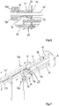
- Fig. 5 and the in Fig. 6 shown detail Fig. 5 show the moment shortly before the mounting of a sleeve 6 accommodated on the envelope gripping device 116 onto the filling tube 10 '.
- the filling tube 10 ' before the sheath is pushed onto the filling tube, centered by means of Darmmit Spotifyringes 18 via a support surface 20 on the support member 14'.
- the support surface 20 forms a cylindrical receiving space 22 on the support member 14 'from.
- the open end of the sheath 6 can be brought into contact with the gutter receiving ring 18 which can be moved along the filling tube 10 ', with the guttering ring 18 being displaced by means of the sheath 6 in the direction of the end of the stuffing tube 10' movably arranged on the receiving part 8.
- the intestinal loading unit 112 comprises a slide 128, which engages between the gripping elements 124, 124 '. About this the sheath 6 and also the Darmmit shakingring in the direction of the receiving part 8 rotatably arranged end of the filling tube 10 'is pushed.
- an adjusting device 24 for the support parts 14, 14 ' is arranged on the casing brake unit 126, which influences the position of the support parts 14, 14' along the filling pipes 10, 10 '.
- the actuating device 24 coupled to the casing brake unit comprises an actuator 26 for adjusting the support part in the direction of the receiving part 8 for the filling pipes 10, 10 '.
- the adjusting device 24 has a return plate 28 which is adapted to move the support sleeve 12 'at the filling tube 10' located in the upper loading position in the direction of the open end 16 'of the filling tube when the sleeve is wound up is.
- the support members 14, 14 'each have a driver 29 which is coupled to a portion of the intestinal brake unit 126 or the intestinal loading unit 112.
- Intestinal braking unit 126 and / or intestinal loading unit have for this purpose an adjusting device which is adapted to the support parts 14, 14 'during the Auf convinceds a tubular casing on a respective filling tube 10, 10' and / or during the contacting with the intestinal brake unit 126 in Direction of the receiving part 8 to move.
- the adjusting device is arranged in a further embodiment, to move the support members 14, 14 'after pulling the sheath on the filling tube 10' in the loading position in the direction of the open end of a respective filling tube.
- the supporting parts 14, 14 'accommodated movably along the support device 12 each have a guide carriage 30, 30', which are movable along a guide 32, 32 ', aligned parallel to the longitudinal axis of the filling tube, with the guide struts 34, 34'.
- Fig. 7 and 8th 3 shows the loading step in which the slider 128 of the intestinal loading unit 112 has pushed the sheath 6 onto the filling tube 10 'in the upper position on the filling device 2.
- the distance between the gripping elements 124, 124 ' is to be selected on the envelope gripping device 116 so that the outer circumference of the sheath 6 is not clamped, but the shell by means of the slider 128 between the gripping elements can be moved.
- Darmmit Spotifyringes 18 now takes over the shell 6, the alignment or centering function of the filling tube 10 'to the support sleeve 14', wherein the sheath 6 with a support surface 20 '(FIG. Fig.
- Fig. 7 and 8th illustrate the filling of the sheath 6 on the filling tube 10 in the lower filling position, wherein the Darmmit shakingring 18 moves on the filling tube 10 in the direction of the front end 16
- the filling tube 10 is now aligned in the lower position over the moving to the end 16 of the filling tube 10 Darmmit shakingring 18 to the support member 14.
- the slider 128 remains during the movement of the support member 14 'in the end of the filling tube 10' approximate position.
- the return plate 28 engages the guide carriage 30' for the support member 14 '.
- the support member 14 ' which is equipped with an adapted to the diameter of the over the filling tube 10' sheath 6 6 insert 36 overlaps the front end of the shell 6 by the method in its forward position almost completely.
- each support member 14, 14 ' is slidably received with its guide carriage 30, 30' along the guide strut 34, 34 'of the guide 32, 32'.
- the support means 12 has a coaxial with the axis of rotation of the receiving part 8 arranged central strut 40, to which the guide struts 34, 34 'of a respective guide are arranged to extend in parallel.
- the guide struts 34, 34 'and the central strut 40, the rotationally fixed to the receiving part 8 of the Abfoxkopfes 4 are respectively fixedly coupled to each other at the end via a connecting flange 42, about which the support means 12 forms a solid frame structure.
- Fig. 11 detail shown Fig. 10 can be seen, in the central strut 40 with the guide carriage 30, 30 'corresponding recesses 44, 44' are provided, in which portions of the guide carriage are movably received.
- the arranged in a preferred embodiment of the Darmbremsaku 126 retractor 28 engages over a formed in the connecting flange 42 opening 46 in the central strut 40 and cooperates with the driver 29 of a respective guide carriage 30, 30 'of a support member 14, 14' together, in the upper loading position of the filling device is.
- the return actuator 28 has a spring-loaded latching element 48, which can be brought into operative connection with the driver 29 on the guide carriage 30, 30 'and engages behind regions of the guide carriage.
- the receiving part 8 of the turning head 4 is moved as shown in FIG Fig. 9 indicated movement arrow turned 180 degrees or pivoted.
- the filling tube 10 'now equipped with the casing is moved into the filling position and the "empty" filling tube 10 is moved into the upper loading position.
- the then in the loading position filling tube 10 is now, as at Fig. 4 starting, again equipped with a new shell 6.
- the filling tube 10 'located in the lower position, in particular its front end 16', is brought into contact with the casing brake unit 126, the casing brake unit being pushed onto the end 16 'of the filling tube or onto the end of the casing 6.
- the actuator 26 arranged on the intestinal brake unit 126 moves the support part 14 'into its rearward position in the direction of the receiving part 8 Fig. 4 shown initial state produced and a new filling and Be Publishedvorgang to the filling device 2 can start.
Landscapes
- Engineering & Computer Science (AREA)
- Life Sciences & Earth Sciences (AREA)
- Wood Science & Technology (AREA)
- Zoology (AREA)
- Food Science & Technology (AREA)
- Mechanical Engineering (AREA)
- Processing Of Meat And Fish (AREA)
Applications Claiming Priority (1)
| Application Number | Priority Date | Filing Date | Title |
|---|---|---|---|
| DE102017120108.4A DE102017120108B3 (de) | 2017-08-31 | 2017-08-31 | Vorrichtung zum Füllen schlauchförmiger Hüllen |
Publications (4)
| Publication Number | Publication Date |
|---|---|
| EP3449728A2 true EP3449728A2 (fr) | 2019-03-06 |
| EP3449728A3 EP3449728A3 (fr) | 2019-06-19 |
| EP3449728B1 EP3449728B1 (fr) | 2023-12-06 |
| EP3449728C0 EP3449728C0 (fr) | 2023-12-06 |
Family
ID=62982607
Family Applications (1)
| Application Number | Title | Priority Date | Filing Date |
|---|---|---|---|
| EP18191946.5A Active EP3449728B1 (fr) | 2017-08-31 | 2018-08-31 | Dispositif de remplissage d'enveloppes tubulaires |
Country Status (3)
| Country | Link |
|---|---|
| US (1) | US10440966B2 (fr) |
| EP (1) | EP3449728B1 (fr) |
| DE (1) | DE102017120108B3 (fr) |
Families Citing this family (5)
| Publication number | Priority date | Publication date | Assignee | Title |
|---|---|---|---|---|
| CN114476221A (zh) * | 2022-03-01 | 2022-05-13 | 保定全乐生物科技有限公司 | 一种火腿肠式包装血制品及其灌装设备 |
| EP4272564B1 (fr) * | 2022-05-06 | 2025-09-10 | Poly-clip System GmbH & Co. KG | Système de production de produits en forme de saucisses |
| EP4272567B1 (fr) * | 2022-05-06 | 2025-07-02 | Poly-clip System GmbH & Co. KG | Système de production de produits en forme de saucisses |
| EP4272565B1 (fr) * | 2022-05-06 | 2025-07-09 | Poly-clip System GmbH & Co. KG | Procédé de commande d'un dispositif robotique pour fournir une machine d'agrafage avec une alimentation d'enveloppe d'emballage tubulaire |
| EP4272568B1 (fr) * | 2022-05-06 | 2025-07-02 | Poly-clip System GmbH & Co. KG | Procédé de commande d'un dispositif robotique pour fournir une machine d'agrafage avec une alimentation d'enveloppes d'emballage tubulaire |
Family Cites Families (13)
| Publication number | Priority date | Publication date | Assignee | Title |
|---|---|---|---|---|
| US3540075A (en) * | 1967-12-22 | 1970-11-17 | Oscar Paul Kempe | Sausage linker |
| US4437209A (en) * | 1981-11-16 | 1984-03-20 | Union Carbide Corporation | Stuffing method |
| DE4028343A1 (de) * | 1990-09-06 | 1992-03-12 | Handtmann Albert Maschf | Verfahren und vorrichtung zum herstellen von wuersten |
| JP3477728B2 (ja) * | 1992-04-30 | 2003-12-10 | ハイテック株式会社 | 連鎖状ソーセージ等の製造装置 |
| JP3713755B2 (ja) * | 1995-07-21 | 2005-11-09 | ハイテック株式会社 | 所望のリンク長を有したソーセージ等の製造装置 |
| DE19810046C1 (de) * | 1998-03-09 | 1999-12-09 | Handtmann Albert Maschf | Vorrichtung und Verfahren zum Trennen von Würsten |
| WO2000065921A1 (fr) * | 1999-05-02 | 2000-11-09 | Hitec Co., Ltd. | Procede et dispositif de fabrication d'aliments en chaine tels que des saucissons |
| DE19952102A1 (de) * | 1999-10-29 | 2001-05-10 | Vemag Maschinen & Anlagenbau Gmbh | Verfahren und Vorrichtung zur Herstellung von kettenähnlichen Lebensmittelprodukten wie Würstchen oder dgl. |
| DE502006002598D1 (de) * | 2006-09-19 | 2009-02-26 | Handtmann Albert Maschf | Vorrichtung und Verfahren zum Abteilen eines gefüllten Wurststrangs |
| US7704131B1 (en) * | 2008-12-30 | 2010-04-27 | Kraft Foods Global Brands Llc | Apparatus for forming spaced intervals in a stuffed casing and method thereof |
| DE202010006603U1 (de) * | 2010-05-07 | 2010-08-05 | Vemag Maschinenbau Gmbh | Darmgreifvorrichtung |
| US8641484B1 (en) * | 2013-02-15 | 2014-02-04 | Marel Meat Processing Inc. | Variable speed linker |
| DE202013010285U1 (de) | 2013-11-13 | 2015-03-06 | Vemag Maschinenbau Gmbh | Vorrichtung zum Füllen schlauchförmiger Hüllen |
-
2017
- 2017-08-31 DE DE102017120108.4A patent/DE102017120108B3/de active Active
-
2018
- 2018-08-29 US US16/116,406 patent/US10440966B2/en active Active
- 2018-08-31 EP EP18191946.5A patent/EP3449728B1/fr active Active
Also Published As
| Publication number | Publication date |
|---|---|
| DE102017120108B3 (de) | 2018-08-16 |
| US20190059402A1 (en) | 2019-02-28 |
| EP3449728B1 (fr) | 2023-12-06 |
| EP3449728C0 (fr) | 2023-12-06 |
| EP3449728A3 (fr) | 2019-06-19 |
| US10440966B2 (en) | 2019-10-15 |
Similar Documents
| Publication | Publication Date | Title |
|---|---|---|
| EP3449728B1 (fr) | Dispositif de remplissage d'enveloppes tubulaires | |
| DE2614184C2 (de) | Stopfrohranordnung zum Füllen von Wursthüllen | |
| EP1844659B1 (fr) | Nouage direct d'un dispositif d'agrafe de saucisson et d'alimentation de saucisson | |
| EP0962143B1 (fr) | Dispositif pour la fabrication de saucisses | |
| DE69926850T2 (de) | Reifenwulstwickelvorrichtung und verfahren | |
| EP0386409A2 (fr) | Procédé d'emballage de manchons tubulaires plissés dans un filet tubulaire pour le traitement ultérieur en boyaux pour une machine de bourrage automatique de saucisses | |
| DE69027573T2 (de) | Verfahren und Maschine zum Ausbilden einer Rolle drahtförmigen Materials | |
| DE2411020A1 (de) | Verfahren und vorrichtung zur automatischen herstellung von abgepackten fleischwaren, wie wurstwaren | |
| EP0025923A1 (fr) | Procédé et dispositif pour la production automatique de saucisses en chapelets en utilisant des enveloppes synthétiques comme boyaux | |
| EP1967073A1 (fr) | Réglage d'extension automatique | |
| EP0110343A1 (fr) | Procédé et dispositif pour charger séquentiellement le tube de remplissage d'une machine à bourrer et ligaturer les saucisses de longueurs de boyaux de saucisses | |
| DE3244085C1 (de) | Verfahren und Vorrichtung zum OEffnen,axialen Raffen und Abtrennen von duennwandigem Schlauchhuellenmaterial und zum anschliessenden UEberfuehren der dadurch gebildeten Raupen an eine Weiterverarbeitungsstelle | |
| EP2873324B1 (fr) | Dispositif de remplissage d'enveloppes en forme de tuyau | |
| EP0562229B1 (fr) | Pince de sertissage pour extrémités des fils | |
| EP3178326B1 (fr) | Procédé et dispositif destinés au remplissage d'enveloppes de saucisses | |
| EP2372848B1 (fr) | Dispositif et procédé de mise en place de câbles avec des manchons | |
| EP2227963B1 (fr) | Dispositif de retenue | |
| DE3009133A1 (de) | Vorrichtung zur automatischen herstellung von rohrelementen aus kunststoff | |
| DE4019483C1 (fr) | ||
| EP0131753A1 (fr) | Procédé et dispositif pour le plissage de boyaux tubulaires | |
| DE69414804T2 (de) | Apparat zum Beschicken des Füllrohrs mit Schlauchhüllen und Verfahren zu seiner Anwendung | |
| EP3566584B1 (fr) | Procédé de montage d'un tube de remplissage ainsi que dispositif de remplissage des enveloppes tubulaires | |
| DE2515344C2 (de) | Vorrichtung zum fortlaufenden Herstellen von Wulstdraht-Ringen | |
| DE2344226A1 (de) | Vorrichtung zum abteilen von packungen, insbesondere wuersten, von einem gefuellten schlauch | |
| DE29819328U1 (de) | Vorrichtung zum portionierenden Abfüllen von pastösen Produkten |
Legal Events
| Date | Code | Title | Description |
|---|---|---|---|
| PUAI | Public reference made under article 153(3) epc to a published international application that has entered the european phase |
Free format text: ORIGINAL CODE: 0009012 |
|
| STAA | Information on the status of an ep patent application or granted ep patent |
Free format text: STATUS: THE APPLICATION HAS BEEN PUBLISHED |
|
| AK | Designated contracting states |
Kind code of ref document: A2 Designated state(s): AL AT BE BG CH CY CZ DE DK EE ES FI FR GB GR HR HU IE IS IT LI LT LU LV MC MK MT NL NO PL PT RO RS SE SI SK SM TR |
|
| AX | Request for extension of the european patent |
Extension state: BA ME |
|
| PUAL | Search report despatched |
Free format text: ORIGINAL CODE: 0009013 |
|
| AK | Designated contracting states |
Kind code of ref document: A3 Designated state(s): AL AT BE BG CH CY CZ DE DK EE ES FI FR GB GR HR HU IE IS IT LI LT LU LV MC MK MT NL NO PL PT RO RS SE SI SK SM TR |
|
| AX | Request for extension of the european patent |
Extension state: BA ME |
|
| RIC1 | Information provided on ipc code assigned before grant |
Ipc: A22C 11/02 20060101AFI20190516BHEP |
|
| STAA | Information on the status of an ep patent application or granted ep patent |
Free format text: STATUS: REQUEST FOR EXAMINATION WAS MADE |
|
| 17P | Request for examination filed |
Effective date: 20191219 |
|
| RBV | Designated contracting states (corrected) |
Designated state(s): AL AT BE BG CH CY CZ DE DK EE ES FI FR GB GR HR HU IE IS IT LI LT LU LV MC MK MT NL NO PL PT RO RS SE SI SK SM TR |
|
| STAA | Information on the status of an ep patent application or granted ep patent |
Free format text: STATUS: EXAMINATION IS IN PROGRESS |
|
| 17Q | First examination report despatched |
Effective date: 20210624 |
|
| GRAP | Despatch of communication of intention to grant a patent |
Free format text: ORIGINAL CODE: EPIDOSNIGR1 |
|
| STAA | Information on the status of an ep patent application or granted ep patent |
Free format text: STATUS: GRANT OF PATENT IS INTENDED |
|
| INTG | Intention to grant announced |
Effective date: 20230816 |
|
| RIN1 | Information on inventor provided before grant (corrected) |
Inventor name: LEWIN, ALEXANDER Inventor name: GROTE, OLAF Inventor name: MATTHIES, HEINER Inventor name: HAGEDORN, JAN-NILS Inventor name: MACH, MATTHIAS |
|
| GRAS | Grant fee paid |
Free format text: ORIGINAL CODE: EPIDOSNIGR3 |
|
| GRAA | (expected) grant |
Free format text: ORIGINAL CODE: 0009210 |
|
| STAA | Information on the status of an ep patent application or granted ep patent |
Free format text: STATUS: THE PATENT HAS BEEN GRANTED |
|
| AK | Designated contracting states |
Kind code of ref document: B1 Designated state(s): AL AT BE BG CH CY CZ DE DK EE ES FI FR GB GR HR HU IE IS IT LI LT LU LV MC MK MT NL NO PL PT RO RS SE SI SK SM TR |
|
| REG | Reference to a national code |
Ref country code: GB Ref legal event code: FG4D Free format text: NOT ENGLISH |
|
| REG | Reference to a national code |
Ref country code: DE Ref legal event code: R096 Ref document number: 502018013738 Country of ref document: DE |
|
| REG | Reference to a national code |
Ref country code: CH Ref legal event code: EP |
|
| REG | Reference to a national code |
Ref country code: IE Ref legal event code: FG4D Free format text: LANGUAGE OF EP DOCUMENT: GERMAN |
|
| U01 | Request for unitary effect filed |
Effective date: 20231206 |
|
| U07 | Unitary effect registered |
Designated state(s): AT BE BG DE DK EE FI FR IT LT LU LV MT NL PT SE SI Effective date: 20231211 |
|
| PG25 | Lapsed in a contracting state [announced via postgrant information from national office to epo] |
Ref country code: GR Free format text: LAPSE BECAUSE OF FAILURE TO SUBMIT A TRANSLATION OF THE DESCRIPTION OR TO PAY THE FEE WITHIN THE PRESCRIBED TIME-LIMIT Effective date: 20240307 |
|
| PG25 | Lapsed in a contracting state [announced via postgrant information from national office to epo] |
Ref country code: ES Free format text: LAPSE BECAUSE OF FAILURE TO SUBMIT A TRANSLATION OF THE DESCRIPTION OR TO PAY THE FEE WITHIN THE PRESCRIBED TIME-LIMIT Effective date: 20231206 |
|
| PG25 | Lapsed in a contracting state [announced via postgrant information from national office to epo] |
Ref country code: GR Free format text: LAPSE BECAUSE OF FAILURE TO SUBMIT A TRANSLATION OF THE DESCRIPTION OR TO PAY THE FEE WITHIN THE PRESCRIBED TIME-LIMIT Effective date: 20240307 Ref country code: ES Free format text: LAPSE BECAUSE OF FAILURE TO SUBMIT A TRANSLATION OF THE DESCRIPTION OR TO PAY THE FEE WITHIN THE PRESCRIBED TIME-LIMIT Effective date: 20231206 |
|
| PG25 | Lapsed in a contracting state [announced via postgrant information from national office to epo] |
Ref country code: RS Free format text: LAPSE BECAUSE OF FAILURE TO SUBMIT A TRANSLATION OF THE DESCRIPTION OR TO PAY THE FEE WITHIN THE PRESCRIBED TIME-LIMIT Effective date: 20231206 Ref country code: NO Free format text: LAPSE BECAUSE OF FAILURE TO SUBMIT A TRANSLATION OF THE DESCRIPTION OR TO PAY THE FEE WITHIN THE PRESCRIBED TIME-LIMIT Effective date: 20240306 Ref country code: HR Free format text: LAPSE BECAUSE OF FAILURE TO SUBMIT A TRANSLATION OF THE DESCRIPTION OR TO PAY THE FEE WITHIN THE PRESCRIBED TIME-LIMIT Effective date: 20231206 |
|
| PG25 | Lapsed in a contracting state [announced via postgrant information from national office to epo] |
Ref country code: IS Free format text: LAPSE BECAUSE OF FAILURE TO SUBMIT A TRANSLATION OF THE DESCRIPTION OR TO PAY THE FEE WITHIN THE PRESCRIBED TIME-LIMIT Effective date: 20240406 |
|
| PG25 | Lapsed in a contracting state [announced via postgrant information from national office to epo] |
Ref country code: CZ Free format text: LAPSE BECAUSE OF FAILURE TO SUBMIT A TRANSLATION OF THE DESCRIPTION OR TO PAY THE FEE WITHIN THE PRESCRIBED TIME-LIMIT Effective date: 20231206 |
|
| PG25 | Lapsed in a contracting state [announced via postgrant information from national office to epo] |
Ref country code: SK Free format text: LAPSE BECAUSE OF FAILURE TO SUBMIT A TRANSLATION OF THE DESCRIPTION OR TO PAY THE FEE WITHIN THE PRESCRIBED TIME-LIMIT Effective date: 20231206 |
|
| PG25 | Lapsed in a contracting state [announced via postgrant information from national office to epo] |
Ref country code: SM Free format text: LAPSE BECAUSE OF FAILURE TO SUBMIT A TRANSLATION OF THE DESCRIPTION OR TO PAY THE FEE WITHIN THE PRESCRIBED TIME-LIMIT Effective date: 20231206 Ref country code: SK Free format text: LAPSE BECAUSE OF FAILURE TO SUBMIT A TRANSLATION OF THE DESCRIPTION OR TO PAY THE FEE WITHIN THE PRESCRIBED TIME-LIMIT Effective date: 20231206 Ref country code: RO Free format text: LAPSE BECAUSE OF FAILURE TO SUBMIT A TRANSLATION OF THE DESCRIPTION OR TO PAY THE FEE WITHIN THE PRESCRIBED TIME-LIMIT Effective date: 20231206 Ref country code: IS Free format text: LAPSE BECAUSE OF FAILURE TO SUBMIT A TRANSLATION OF THE DESCRIPTION OR TO PAY THE FEE WITHIN THE PRESCRIBED TIME-LIMIT Effective date: 20240406 Ref country code: CZ Free format text: LAPSE BECAUSE OF FAILURE TO SUBMIT A TRANSLATION OF THE DESCRIPTION OR TO PAY THE FEE WITHIN THE PRESCRIBED TIME-LIMIT Effective date: 20231206 |
|
| PG25 | Lapsed in a contracting state [announced via postgrant information from national office to epo] |
Ref country code: PL Free format text: LAPSE BECAUSE OF FAILURE TO SUBMIT A TRANSLATION OF THE DESCRIPTION OR TO PAY THE FEE WITHIN THE PRESCRIBED TIME-LIMIT Effective date: 20231206 |
|
| PG25 | Lapsed in a contracting state [announced via postgrant information from national office to epo] |
Ref country code: PL Free format text: LAPSE BECAUSE OF FAILURE TO SUBMIT A TRANSLATION OF THE DESCRIPTION OR TO PAY THE FEE WITHIN THE PRESCRIBED TIME-LIMIT Effective date: 20231206 |
|
| U20 | Renewal fee for the european patent with unitary effect paid |
Year of fee payment: 7 Effective date: 20240801 |
|
| REG | Reference to a national code |
Ref country code: DE Ref legal event code: R097 Ref document number: 502018013738 Country of ref document: DE |
|
| PLBE | No opposition filed within time limit |
Free format text: ORIGINAL CODE: 0009261 |
|
| STAA | Information on the status of an ep patent application or granted ep patent |
Free format text: STATUS: NO OPPOSITION FILED WITHIN TIME LIMIT |
|
| 26N | No opposition filed |
Effective date: 20240909 |
|
| REG | Reference to a national code |
Ref country code: CH Ref legal event code: PL |
|
| GBPC | Gb: european patent ceased through non-payment of renewal fee |
Effective date: 20240831 |
|
| PG25 | Lapsed in a contracting state [announced via postgrant information from national office to epo] |
Ref country code: MC Free format text: LAPSE BECAUSE OF FAILURE TO SUBMIT A TRANSLATION OF THE DESCRIPTION OR TO PAY THE FEE WITHIN THE PRESCRIBED TIME-LIMIT Effective date: 20231206 Ref country code: CH Free format text: LAPSE BECAUSE OF NON-PAYMENT OF DUE FEES Effective date: 20240831 |
|
| PG25 | Lapsed in a contracting state [announced via postgrant information from national office to epo] |
Ref country code: GB Free format text: LAPSE BECAUSE OF NON-PAYMENT OF DUE FEES Effective date: 20240831 |
|
| PG25 | Lapsed in a contracting state [announced via postgrant information from national office to epo] |
Ref country code: IE Free format text: LAPSE BECAUSE OF NON-PAYMENT OF DUE FEES Effective date: 20240831 |
|
| U20 | Renewal fee for the european patent with unitary effect paid |
Year of fee payment: 8 Effective date: 20250819 |
|
| PG25 | Lapsed in a contracting state [announced via postgrant information from national office to epo] |
Ref country code: CY Free format text: LAPSE BECAUSE OF FAILURE TO SUBMIT A TRANSLATION OF THE DESCRIPTION OR TO PAY THE FEE WITHIN THE PRESCRIBED TIME-LIMIT; INVALID AB INITIO Effective date: 20180831 |
|
| PG25 | Lapsed in a contracting state [announced via postgrant information from national office to epo] |
Ref country code: HU Free format text: LAPSE BECAUSE OF FAILURE TO SUBMIT A TRANSLATION OF THE DESCRIPTION OR TO PAY THE FEE WITHIN THE PRESCRIBED TIME-LIMIT; INVALID AB INITIO Effective date: 20180831 |