EP3449792A1 - Bodenreinigungsgerät und verfahren zu dessen betrieb - Google Patents
Bodenreinigungsgerät und verfahren zu dessen betrieb Download PDFInfo
- Publication number
- EP3449792A1 EP3449792A1 EP18181671.1A EP18181671A EP3449792A1 EP 3449792 A1 EP3449792 A1 EP 3449792A1 EP 18181671 A EP18181671 A EP 18181671A EP 3449792 A1 EP3449792 A1 EP 3449792A1
- Authority
- EP
- European Patent Office
- Prior art keywords
- floor cleaning
- operating
- floor
- user
- cleaning appliance
- Prior art date
- Legal status (The legal status is an assumption and is not a legal conclusion. Google has not performed a legal analysis and makes no representation as to the accuracy of the status listed.)
- Granted
Links
Images
Classifications
-
- A—HUMAN NECESSITIES
- A47—FURNITURE; DOMESTIC ARTICLES OR APPLIANCES; COFFEE MILLS; SPICE MILLS; SUCTION CLEANERS IN GENERAL
- A47L—DOMESTIC WASHING OR CLEANING; SUCTION CLEANERS IN GENERAL
- A47L5/00—Structural features of suction cleaners
- A47L5/12—Structural features of suction cleaners with power-driven air-pumps or air-compressors, e.g. driven by motor vehicle engine vacuum
- A47L5/22—Structural features of suction cleaners with power-driven air-pumps or air-compressors, e.g. driven by motor vehicle engine vacuum with rotary fans
-
- A—HUMAN NECESSITIES
- A47—FURNITURE; DOMESTIC ARTICLES OR APPLIANCES; COFFEE MILLS; SPICE MILLS; SUCTION CLEANERS IN GENERAL
- A47L—DOMESTIC WASHING OR CLEANING; SUCTION CLEANERS IN GENERAL
- A47L9/00—Details or accessories of suction cleaners, e.g. mechanical means for controlling the suction or for effecting pulsating action; Storing devices specially adapted to suction cleaners or parts thereof; Carrying-vehicles specially adapted for suction cleaners
- A47L9/28—Installation of the electric equipment, e.g. adaptation or attachment to the suction cleaner; Controlling suction cleaners by electric means
- A47L9/2857—User input or output elements for control, e.g. buttons, switches or displays
-
- A—HUMAN NECESSITIES
- A47—FURNITURE; DOMESTIC ARTICLES OR APPLIANCES; COFFEE MILLS; SPICE MILLS; SUCTION CLEANERS IN GENERAL
- A47L—DOMESTIC WASHING OR CLEANING; SUCTION CLEANERS IN GENERAL
- A47L9/00—Details or accessories of suction cleaners, e.g. mechanical means for controlling the suction or for effecting pulsating action; Storing devices specially adapted to suction cleaners or parts thereof; Carrying-vehicles specially adapted for suction cleaners
- A47L9/28—Installation of the electric equipment, e.g. adaptation or attachment to the suction cleaner; Controlling suction cleaners by electric means
-
- A—HUMAN NECESSITIES
- A47—FURNITURE; DOMESTIC ARTICLES OR APPLIANCES; COFFEE MILLS; SPICE MILLS; SUCTION CLEANERS IN GENERAL
- A47L—DOMESTIC WASHING OR CLEANING; SUCTION CLEANERS IN GENERAL
- A47L9/00—Details or accessories of suction cleaners, e.g. mechanical means for controlling the suction or for effecting pulsating action; Storing devices specially adapted to suction cleaners or parts thereof; Carrying-vehicles specially adapted for suction cleaners
- A47L9/28—Installation of the electric equipment, e.g. adaptation or attachment to the suction cleaner; Controlling suction cleaners by electric means
- A47L9/2805—Parameters or conditions being sensed
- A47L9/281—Parameters or conditions being sensed the amount or condition of incoming dirt or dust
-
- A—HUMAN NECESSITIES
- A47—FURNITURE; DOMESTIC ARTICLES OR APPLIANCES; COFFEE MILLS; SPICE MILLS; SUCTION CLEANERS IN GENERAL
- A47L—DOMESTIC WASHING OR CLEANING; SUCTION CLEANERS IN GENERAL
- A47L9/00—Details or accessories of suction cleaners, e.g. mechanical means for controlling the suction or for effecting pulsating action; Storing devices specially adapted to suction cleaners or parts thereof; Carrying-vehicles specially adapted for suction cleaners
- A47L9/28—Installation of the electric equipment, e.g. adaptation or attachment to the suction cleaner; Controlling suction cleaners by electric means
- A47L9/2805—Parameters or conditions being sensed
- A47L9/2821—Pressure, vacuum level or airflow
-
- A—HUMAN NECESSITIES
- A47—FURNITURE; DOMESTIC ARTICLES OR APPLIANCES; COFFEE MILLS; SPICE MILLS; SUCTION CLEANERS IN GENERAL
- A47L—DOMESTIC WASHING OR CLEANING; SUCTION CLEANERS IN GENERAL
- A47L9/00—Details or accessories of suction cleaners, e.g. mechanical means for controlling the suction or for effecting pulsating action; Storing devices specially adapted to suction cleaners or parts thereof; Carrying-vehicles specially adapted for suction cleaners
- A47L9/28—Installation of the electric equipment, e.g. adaptation or attachment to the suction cleaner; Controlling suction cleaners by electric means
- A47L9/2805—Parameters or conditions being sensed
- A47L9/2826—Parameters or conditions being sensed the condition of the floor
-
- A—HUMAN NECESSITIES
- A47—FURNITURE; DOMESTIC ARTICLES OR APPLIANCES; COFFEE MILLS; SPICE MILLS; SUCTION CLEANERS IN GENERAL
- A47L—DOMESTIC WASHING OR CLEANING; SUCTION CLEANERS IN GENERAL
- A47L9/00—Details or accessories of suction cleaners, e.g. mechanical means for controlling the suction or for effecting pulsating action; Storing devices specially adapted to suction cleaners or parts thereof; Carrying-vehicles specially adapted for suction cleaners
- A47L9/28—Installation of the electric equipment, e.g. adaptation or attachment to the suction cleaner; Controlling suction cleaners by electric means
- A47L9/2836—Installation of the electric equipment, e.g. adaptation or attachment to the suction cleaner; Controlling suction cleaners by electric means characterised by the parts which are controlled
-
- A—HUMAN NECESSITIES
- A47—FURNITURE; DOMESTIC ARTICLES OR APPLIANCES; COFFEE MILLS; SPICE MILLS; SUCTION CLEANERS IN GENERAL
- A47L—DOMESTIC WASHING OR CLEANING; SUCTION CLEANERS IN GENERAL
- A47L9/00—Details or accessories of suction cleaners, e.g. mechanical means for controlling the suction or for effecting pulsating action; Storing devices specially adapted to suction cleaners or parts thereof; Carrying-vehicles specially adapted for suction cleaners
- A47L9/28—Installation of the electric equipment, e.g. adaptation or attachment to the suction cleaner; Controlling suction cleaners by electric means
- A47L9/2836—Installation of the electric equipment, e.g. adaptation or attachment to the suction cleaner; Controlling suction cleaners by electric means characterised by the parts which are controlled
- A47L9/2842—Suction motors or blowers
Definitions
- the invention relates to a method for operating a floor cleaning device, for example, hand-held vacuum cleaner, with at least one operable in different operating modes electrically driven cleaning motor, with multiple controls for manually entering an operating instruction by the user and with an electronic control device, in the logic operations of the operating instructions the operating modes are stored.
- the invention also relates to a floor cleaning device for carrying out the method.
- Floor cleaning devices are, for example, from the DE 10 2016 118 248 A1 .
- DE 10 2012 109 627 A1 previously known.
- the hand-held vacuum cleaner described therein has a suction fan, which is operated by a suction fan motor and a header, which also has an electric motor. With a pressure sensor, a negative pressure within the suction line can be determined.
- the DE 10 2015 100 977 A1 describes a cleaning robot with an optical measuring device for determining a type of soil.
- a handling parameter can be determined on a device driven by an electric motor.
- the DE 10 2016 101 040 describes means by which the suction cross-section of a suction channel can be adjusted at a suction cleaning device.
- Floor cleaning equipment and especially hand-held vacuum cleaners have a control panel having controls that are formed, for example. Of switches. With the help of these switches, the user can enter an operating instruction. So he can, for example, achieve by the operation of a switch that the device starts its operation by, for example, the suction fan works at maximum power. By operating another control element, the operating mode can be changed, for example, to the effect that the suction fan operates at reduced power or that a certain negative pressure within the suction power must not be exceeded. Furthermore, it is possible to adjust the operating parameters of the floor cleaning device to a specific type of soil by the operation of a control element.
- the linking of an operating instruction with a specific operating mode is permanently integrated in an electronic control device and can not be manipulated by the user.
- the invention has for its object to provide measures with which the operating spectrum of a floor cleaning device to the individual needs of the user is customizable.
- the logical links of the operational specifications with the operating modes can be changed by the user.
- a universal data display and input device is used, which can be connected via a data transmission link with the floor cleaning device.
- the operating modes can be modified, for example, a further operating mode can be added to a predetermined catalog of different operating modes, which is linked to a control element.
- One or more operating elements can be provided, which can each be linked to an operating mode, so that upon actuation of one of the operating elements, the operating mode assigned to it is assumed. The assignment can be changed from the outside.
- the data transmission path can be a wired transmission path which, for example, can be realized by a USB cable.
- the floor cleaning device or its control device communicates wirelessly with the data display and input device. This can be done via a WLAN connection, eg via WPS. For this purpose, it is particularly advantageous if the floor cleaning device is integrated into a local network, in particular WLAN network.
- the data exchange between the data display and input device can also be done via other wireless protocols, eg. Via Bluetooth. It is also conceivable that the data exchange takes place via the mobile radio network.
- the floor cleaning device may, for example, have a configuration memory in which various configurations are stored, each configuration corresponding to a link.
- the links are selected via a graphic display in the data display and input device, whereby data from external computing devices (cloud) can also be used for this purpose the user suggestions are made, which operating modes, for example, are suitable for cleaning certain types of soil.
- the floor cleaning device has a floor detection sensor, for example an ultrasonic sensor, with which the quality of the floor to be cleaned is detected.
- the floor to be cleaned can be classified with a floor type, eg hard floor or the type of carpet.
- the floor sensor can be arranged in an attachment for this purpose. But it is also envisaged that the user manually specifies the soil type.
- a data processing program that interacts with the data display and input device or is operated by the data display and input device, a catalog of different types of soil can be made available to the user.
- the user can select the types of flooring that are suitable for his individual cleaning tasks. From a suction parameter catalog, the user can then assign suitable operating modes to each candidate floor type.
- Various controls can be logically linked to different types of floors, so that the operation of a particular control element causes the floor cleaning device automatically adjusts to the best for cleaning this type of soil parameters. It is also possible to specify different operating modes from the specifications.
- the operating modes include, in particular, the cleaning intensity, the cleaning quality, a pushing force with which the floor cleaning appliance has to be pushed over the floor. It may be a minimum or maximum thrust.
- the operating modes further include the speed of one or more electric motors and, in particular, a minimum or maximum speed.
- Operating modes may also be a Saugkanalquerrough, a suction or a minimum negative pressure in the suction channel.
- An attachment can have mechanical elements, for example sealing lips, whose position can be used as an operating mode.
- Another mode of operation may be a minimum battery life if the floor cleaning device is an accumulator-powered device maximum volume.
- the configuration data which are generated by means of the data display and input device, can be stored in a memory of the floor cleaning device.
- the resulting links or the operating parameters derived therefrom for an electric motor can be transmitted to an attachment, for example a brush device. But it is also envisaged that the header has its own configuration memory in which the configurations are stored.
- the floor cleaning device can be operated in an automatic mode, in which a soil detection sensor, for example, by detecting a negative pressure in the suction channel or the pushing force can determine the soil type. On the basis of such determined soil type value then operating parameters can be set. If the data display and input device is designed such that it makes a proposal to the user for selecting an operating mode, then it can also be provided that the user is informed about the advantages and disadvantages of the operating mode, for example the quality of cleaning, the volume, the handling and / or the battery life of a cordless device. To set an operating mode and in particular a suction parameter, in particular the current floor can be detected and grouped into a floor group.
- this information is transmitted to the control device of the floor cleaning device.
- the user can make a proposed, but freely selectable setting for this type of soil.
- the user may also select whether to treat other floors that fall into the same floor group with this profile in a semi-automatic operation.
- a global routine is possible, which derives the parameters determined by a soil on further soils. This can be done by detecting the pushing force.
- a floor cleaning device is further developed in such a way that by operating various operating elements customer-specific operating modes can be used, wherein one of these modes of operation may also be an automatic mode.
- the required change in the logic operations between operating and operating mode is carried out via a universal data display and input device, in which case configuration data are changed in a configuration memory of the electrical control device.
- An inventive floor cleaning device 1 has a suction fan 2, which has an electric motor.
- a program-controlled electronic control device 6 which may be formed by a microcontroller o. The like.
- a control panel 9 On the outside of the housing is a control panel 9 with controls 9.0, 9.1, 9.2 and 9.3, which are each switch or button.
- a suction nozzle of the floor cleaning device 1 is inserted in a header 3, which, for example, may have a brush roller driven by an electric motor.
- the reference numeral 5 designates control commands that the electronic control device 6 can deliver to the electric motors of the suction blower 2 or the attachment 3 in order, for example, to specify their speed, their line recording or other operating parameters.
- a sensor 4 is provided with which, for example, the soil properties of the soil to be cleaned can be determined. Sensor data 7 of the sensor 4 are transmitted to the electronic control device 6.
- the sensor 4 may be assigned in the suction device 2 or the attachment 3. If the sensor 4 is assigned to the attachment 3, then a line connection between the attachment 3 and the control device 6 can be provided, with which the sensor data are transmitted.
- the controls 9.0, 9.1, 9.2 and 9.3 are connected to a data line with the electronic control device 6. An operating instruction can be entered via this data line. This is done by the operation of one or more of the controls 9.0, 9.1, 9.2 or 9.3.
- configuration data 8.0, 8.1, 8.2, 8.3 are deposited, which are logical links between operating modes for operating the suction fan 2 or the attachment 3 with an individualized by the operation of one of the controls 9.0 to 9.3 operating instructions 10.
- the actuation of one of the operating elements 9.0 to 9.3 triggers a special operating instruction 10.
- the links between this special operating instruction 10 and a specific operating mode are stored in the configuration data 8.0 to 8.3.
- the operating mode assigned to it via the configuration data 8.0 to 8.3 is transmitted to the suction fan 2 or the front attachment 3.
- the suction fan 2 or the attachment 3 is then operated, for example, in a limited power range.
- the stored in the configuration memory 8 configurations 8.1, 8.2, 8.3 can be changed by a data display and input device 13.
- the electronic control device 6 communicates via a communication interface 11 and a data transmission path 12 with a communication interface 16 of the data display and input device 13. It may be a WLAN connection, a connection via the mobile network or an individual, for example. Wired data transmission act.
- a screen of the data display and input device 13 shows the user a floor type catalog 14 in which typical soils to be cleaned are displayed, for example hard floors, carpets, wooden floors etc.
- a suction parameter catalog 15 typical and / or optimal suction parameters or other operating parameters for kept the control of the suction fan or the attachment, which can take over or change the user.
- the user can specify a user-specific mode via a selection, how intensively he wants to clean which floors.
- predefined stages / positions of the operating elements 9.1, 9.2, 9.3 can be adapted and changed. Each control element thus forms an individual function key.
- the reprogramming of the functions of the function key is preferably carried out by means of an app on a mobile terminal.
- On the screen of the data display and terminal 13 can be displayed which attachment used at the moment.
- the operating parameters of this attachment can be menu-controlled via inputs to the data display and input device 13 modify. It can be parameters such as the cleaning intensity or the pushing force for the floor cleaning device 1 as such or the floor cleaning device 1 in combination with a header 3 set. These parameters can also be set for different different attachments.
- it is possible to specify the suction power for example by a sealing lip setting or by limiting an engine power. The suction power can be done both by changing the operating parameters of the attachment 3 and the suction fan 2 of the main unit.
- the user can also be displayed the expected consequence of his preselected setting, for example the cleaning quality, the volume, the handling or an accumulator running time.
- the setting of the individual operating mode is preferably carried out using the bottom detection sensor 4, which is, for example, an ultrasonic sensor and which is able to detect different types of soil.
- This sensor may be associated with the header so that the information from the header is transmitted via the main unit to the data display and input device 13.
- the user can then make a desired setting for each and in particular for the current soil type.
- Via the catalog 14 further soil types can be selected and individual settings assigned to them.
- the soil type catalog 14 shows the user all available soil types and makes with a Saugparameterkatalog 15 proposals on cleaning profiles, with which the respective type of soil can be optimally cleaned. The user can accept these specifications or make modifications.
- a global routine is also possible that derives the ground-determined parameters to other soils, e.g. by detecting the pushing forces of a type of soil, which are then derived to other similar soil types.
- the desired configurations are then transmitted via the data communication link 12 to the electronic controller 6, where they are stored in the configuration memory 8.
- the floor cleaning device controls its suction fan 2 or the attachment 3 according to the individually stored configurations.
- the attachment 3 has its own control device 6, in which the configuration data can be stored.
- the reference numeral 9.0 may designate a main operating element for turning on and off. It can also designate an operating element with which the factory settings can be restored. Alternatively, it is also possible that the reference numeral 9.0 designates a separate operating element, when actuated not the individual configuration is used, but a configuration of a factory setting.
- the factory setting can, for example, be stored in a main configuration 8.
Landscapes
- Engineering & Computer Science (AREA)
- Mechanical Engineering (AREA)
- Electric Vacuum Cleaner (AREA)
Abstract
Description
- Die Erfindung betrifft ein Verfahren zum Betrieb eines Bodenreinigungsgerätes, bspw. handgeführten Staubsaugers, mit zumindest einem in verschiedenen Betriebsmodi betreibbaren elektrisch angetriebenen Reinigungsmotor, mit mehreren Bedienelementen zur manuellen Eingabe einer Betriebsvorgabe durch den Benutzer und mit einer elektronischen Steuereinrichtung, in der logische Verknüpfungen der Betriebsvorgaben zu den Betriebsmodi hinterlegt sind.
- Die Erfindung betrifft darüber hinaus ein Bodenreinigungsgerät zur Durchführung des Verfahrens.
- Bodenreinigungsgeräte sind bspw. aus den
DE 10 2016 118 248 A1 ,DE 10 2012 109 627 A1 vorbekannt. Der dort beschriebene handgeführte Staubsauger besitzt ein Sauggebläse, das von einem Sauggebläsemotor betrieben wird und einem Vorsatzgerät, welches ebenfalls einen Elektromotor aufweist. Mit einem Drucksensor kann ein Unterdruck innerhalb der Saugleitung ermittelt werden. - Die
DE 10 2015 100 977 A1 beschreibt einen Reinigungsroboter mit einer optischen Messeinrichtung zur Bestimmung eines Bodentyps. - Aus der
DE 10 2014 110 083 A1 ist ein Verfahren bekannt, bei dem an einem elektromotorisch angetriebenen Gerät ein Handhabungsparameter ermittelbar ist. - Die
DE 10 2016 101 040 beschreibt Mittel, mit denen der Saugquerschnitt eines Saugkanals an einer Saugreinigungseinrichtung verstellt werden kann. - Bodenreinigungsgeräte und insbesondere handgeführte Staubsauger besitzen ein Bedienfeld, das Bedienelemente aufweist, die bspw. von Schaltern ausgebildet sind. Mit Hilfe dieser Schalter kann der Benutzer eine Betriebsvorgabe eingeben. So kann er bspw. durch die Betätigung eines Schalters erreichen, dass das Gerät seinen Betrieb aufnimmt, indem bspw. das Sauggebläse mit maximaler Leistung arbeitet. Durch Betätigen eines anderen Bedienelementes lässt sich der Betriebsmodus ändern, bspw. dahingehend, dass das Sauggebläse mit verminderter Leistung arbeitet oder dass ein bestimmter Unterdruck innerhalb der Saugleistung nicht unterschritten werden darf. Ferner ist es möglich, durch die Betätigung eines Bedienelementes die Betriebsparameter des Bodenreinigungsgerätes an einen bestimmten Bodentyp anzupassen.
- Die Verknüpfung einer Betriebsvorgabe mit einem bestimmten Betriebsmodus ist fest in einer elektronischen Steuereinrichtung integriert und ist vom Benutzer nicht manipulierbar.
- Der Erfindung liegt die Aufgabe zugrunde, Maßnahmen anzugeben, mit denen das Betriebsspektrum eines Bodenreinigungsgerätes an die individuellen Bedürfnisse des Benutzers anpassbar ist.
- Gelöst wird die Aufgabe durch die in den Ansprüchen angegebene Erfindung.
- Erfindungsgemäß können die logischen Verknüpfungen der Betriebsvorgaben mit den Betriebsmodi, die in einer elektronischen Steuereinrichtung hinterlegt sind, vom Benutzer geändert werden. Hierzu wird ein universelles Datensicht- und -eingabegerät verwendet, welches über eine Datenübertragungsstrecke mit dem Bodenreinigungsgerät verbunden werden kann. Mittels des universellen Datensicht- und -eingabegerätes können auch die Betriebsmodi modifiziert werden, bspw. kann einem vorgegebenen Katalog von verschiedenen Betriebsmodi ein weiterer Betriebsmodus hinzugefügt werden, der mit einem Bedienelement verknüpft wird. Es können ein oder mehrere Bedienelemente vorgesehen sein, die jeweils mit einem Betriebsmodus verknüpft werden können, so dass bei der Betätigung eines der Bedienelemente der ihm zugeordnete Betriebsmodus eingenommen wird. Die Zuordnung kann von außen her geändert werden. Bei der Datenübertragungsstrecke kann es sich um eine drahtgebundene Übertragungsstrecke handeln, die bspw. durch ein USB-Kabel verwirklichbar ist. Es ist aber bevorzugt, dass das Bodenreinigungsgerät bzw. dessen Steuereinrichtung drahtlos mit dem Datensicht- und -eingabegerät kommuniziert. Dies kann über eine WLAN-Verbindung, bspw. über WPS, erfolgen. Hierzu ist es insbesondere von Vorteil, wenn das Bodenreinigungsgerät in ein lokales Netzwerk, insbesondere WLAN-Netzwerk integriert ist. Der Datenaustausch zwischen dem Datensicht- und -eingabegerät kann aber auch über andere drahtlose Protokolle, bspw. über Bluetooth erfolgen. Denkbar ist auch, dass der Datenaustausch über das Mobilfunknetz erfolgt. Das Bodenreinigungsgerät kann bspw. einen Konfigurationsspeicher aufweisen, in dem verschiedene Konfigurationen abgespeichert sind, wobei jede Konfiguration einer Verknüpfung entspricht. Die Verknüpfungen werden über eine grafische Anzeige im Datensicht- und Eingabegerät gewählt, wobei hierzu auch Daten von externen Recheneinrichtungen (Cloud) verwendet werden können, mit denen dem Benutzer Vorschläge unterbreitet werden, welche Betriebsmodi bspw. zur Reinigung bestimmter Bodentypen geeignet sind. Es ist insbesondere von Vorteil, wenn das Bodenreinigungsgerät einen Bodenerkennungssensor, bspw. einen Ultraschallsensor, aufweist, mit dem die Qualität des zu reinigenden Bodens erkannt wird. Der zu reinigende Boden kann mit einem Bodentyp klassifiziert werden, bspw. Hartboden oder die Art des Teppichs. Der Bodensensor kann hierzu in einem Vorsatzgerät angeordnet sein. Es ist aber auch vorgesehen, dass der Benutzer manuell die Bodenart vorgibt. Über ein Datenverarbeitungsprogramm, das mit dem Datensicht- und -eingabegerät zusammenwirkt oder vom Datensicht- und -eingabegerät betrieben wird, kann dem Benutzer ein Katalog über verschiedene Bodentypen zur Verfügung gestellt werden. Der Benutzer kann aus diesem Katalog die Bodentypen auswählen, die für seine individuellen Reinigungsaufgaben in Betracht kommen. Aus einem Saugparameterkatalog kann der Benutzer dann jedem in Frage kommenden Bodentyp geeignete Betriebsmodi zuordnen. Verschiedene Bedienelemente können logisch mit verschiedenen Bodentypen verknüpft werden, so dass die Betätigung eines bestimmten Bedienelementes dazu führt, dass sich das Bodenreinigungsgerät selbsttätig auf die zum Reinigen dieses Bodentyps günstigsten Parameter einstellt. Es lassen sich auch von den Vorgaben abweichende Betriebsmodi vorgeben. Die Betriebsmodi umfassen insbesondere die Reinigungsintensität, die Reinigungsqualität, eine Schubkraft, mit der das Bodenreinigungsgerät über den Boden geschoben werden muss. Es kann sich hierbei um eine minimale oder maximale Schubkraft handeln. Die Betriebsmodi umfassen ferner die Drehzahl eines oder mehrerer Elektromotoren und insbesondere eine minimale oder maximale Drehzahl. Betriebsmodi können ferner ein Saugkanalquerschnitt, eine Saugleistung oder ein minimaler Unterdruck im Saugkanal sein. Ein Vorsatzgerät kann mechanische Elemente aufweisen, bspw. Dichtlippen, deren Stellung als Betriebsmodus verwendet werden kann. Ein weiterer Betriebsmodus kann eine minimale Batterielaufzeit sein, wenn es sich bei dem Bodenreinigungsgerät um ein akkumulatorbetriebenes Gerät handelt oder eine maximale Lautstärke sein. Die Konfigurationsdaten, die mit Hilfe des Datensicht- und -eingabegerätes erzeugt werden, können in einem Speicher des Bodenreinigungsgerätes abgelegt werden. Die daraus resultierenden Verknüpfungen bzw. die daraus gewonnenen Betriebsparameter für einen Elektromotor können an ein Vorsatzgerät, bspw. ein Bürstengerät, übertragen werden. Es ist aber auch vorgesehen, dass das Vorsatzgerät einen eigenen Konfigurationsspeicher aufweist, in dem die Konfigurationen abgespeichert sind. Ferner ist es möglich, dass das Bodenreinigungsgerät in einem Automatik-Modus betrieben werden kann, bei dem ein Bodenerkennungssensor bspw. durch Erfassung eines Unterdrucks im Saugkanal oder der Schiebekraft den Bodentyp ermitteln kann. Auf der Basis eines derartig ermittelten Bodentypenwertes können dann Betriebsparameter eingestellt werden. Ist das Datensicht- und -eingabegerät derart ausgebildet, dass es dem Benutzer einen Vorschlag zur Auswahl eines Betriebsmodus unterbreitet, so kann ferner vorgesehen sein, dass dem Benutzer Vor- und Nachteile des Betriebsmodus angezeigt werden, bspw. die Reinigungsqualität, die Lautstärke, das Handling und/ oder die Batterielaufzeit eines Akkugerätes. Zur Einstellung eines Betriebsmodus und insbesondere eines Saugparameters kann insbesondere der aktuelle Boden erkannt und in eine Bodengruppe eingruppiert werden. Ist der Sensor dem Vorsatzgerät zugeordnet, so wird diese Information an die Steuereinrichtung des Bodenreinigungsgerätes übertragen. Der Benutzer kann für diese Bodenart eine vorgeschlagene, aber frei wählbare Einstellung vornehmen. Der Benutzer kann ferner auswählen, ob in einem halbautomatischen Betrieb andere Böden, die in die gleiche Bodengruppe fallen, mit diesem Profil behandelt werden. Alternativ ist auch eine globale Routine möglich, die die von einem Boden ermittelten Parameter auf weitere Böden ableitet. Dies kann durch Erfassung der Schiebekraft erfolgen.
- Mit den zuvor beschriebenen Maßnahmen wird ein Bodenreinigungsgerät dahingehend weitergebildet, dass durch die Betätigung verschiedener Bedienelemente kundenspezifische Betriebsmodi verwendet werden können, wobei einer dieser Betriebsmodi auch ein Automatikmodus sein kann. Die hierzu erforderliche Veränderung der logischen Verknüpfungen zwischen Betriebsvorgabe und Betriebsmodus wird über ein universelles Datensicht- und -eingabegerät durchgeführt, wobei dabei in einem Konfigurationsspeicher der elektrischen Steuereinrichtung Konfigurationsdaten verändert werden.
- Ein Ausführungsbeispiel der Erfindung wird nachfolgend anhand beigefügter Zeichnungen erläutert. Es zeigen:
- Fig. 1
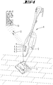
- schematisch einen handgeführten Staubsauger 1 mit Vorsatzgerät 3 und Bedienfeld 9 und einer drahtlosen Kommunikationsstrecke 12 mit einem von einem Smartphone ausgebildeten Datensicht- und -eingabegerät 13,
- Fig. 2
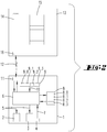
- ein Blockschaltbild.
- Ein erfindungsgemäßes Bodenreinigungsgerät 1 besitzt ein Sauggebläse 2, welches einen Elektromotor aufweist. Innerhalb des Gehäuses des Bodenreinigungsgerätes 1 befindet sich darüber hinaus eine programmgesteuerte elektronische Steuereinrichtung 6, die von einem Mikrokontroller o. dgl. nebst Peripherie ausgebildet sein kann. Auf der Gehäuseaußenseite befindet sich ein Bedienfeld 9 mit Bedienelementen 9.0, 9.1, 9.2 und 9.3, bei denen es sich jeweils um Schalter oder Taster handelt. Ein Saugstutzen des Bodenreinigungsgerätes 1 steckt in einem Vorsatzgerät 3, welches bspw. eine von einem Elektromotor angetriebene Bürstenwalze aufweisen kann.
- Mit der Bezugsziffer 5 sind Steuerbefehle bezeichnet, die die elektronische Steuereinrichtung 6 an die Elektromotoren des Sauggebläses 2 oder des Vorsatzgerätes 3 abgeben kann, um bspw. deren Drehzahl, deren Leitungsaufnahme oder anderweitige Betriebsparameter vorzugeben.
- Es ist ein Sensor 4 vorgesehen, mit dem bspw. die Bodenbeschaffenheit des zu reinigenden Bodens ermittelt werden kann. Sensordaten 7 des Sensors 4 werden an die elektronische Steuereinrichtung 6 übermittelt. Der Sensor 4 kann im Sauggerät 2 oder dem Vorsatzgerät 3 zugeordnet sein. Ist der Sensor 4 dem Vorsatzgerät 3 zugeordnet, so kann eine Leitungsverbindung zwischen Vorsatzgerät 3 und Steuereinrichtung 6 vorgesehen sein, mit der die Sensordaten übertragen werden.
- Die Bedienelemente 9.0, 9.1, 9.2 und 9.3 sind mit einer Datenleitung mit der elektronischen Steuereinrichtung 6 verbunden. Über diese Datenleitung kann eine Betriebsvorgabe eingegeben werden. Dies erfolgt durch die Betätigung eines oder mehrerer der Bedienelemente 9.0, 9.1, 9.2 oder 9.3.
- In einem Konfigurationsspeicher 8 sind Konfigurationsdaten 8.0, 8.1, 8.2, 8.3 hinterlegt, bei denen es sich um logische Verknüpfungen zwischen Betriebsmodi zum Betrieb des Sauggebläses 2 oder des Vorsatzgerätes 3 mit einer durch die Betätigung eines der Bedienelemente 9.0 bis 9.3 individualisierten Betriebsvorgabe 10 handelt. Die Betätigung eines der Bedienelemente 9.0 bis 9.3 löst eine spezielle Betriebsvorgabe 10 aus. Die Verknüpfungen zwischen dieser speziellen Betriebsvorgabe 10 und einem bestimmten Betriebsmodus ist in den Konfigurationsdaten 8.0 bis 8.3 hinterlegt. Bei der Betätigung eines der Bedienelemente 9.0 bis 9.3 wird der ihm über die Konfigurationsdaten 8.0 bis 8.3 zugeordnete Betriebsmodus an das Sauggebläse 2 oder das Vorsatzgerät 3 übertragen. Das Sauggebläse 2 oder das Vorsatzgerät 3 wird dann bspw. in einem beschränkten Leistungsbereich betrieben.
- Die im Konfigurationsspeicher 8 abgelegten Konfigurationen 8.1, 8.2, 8.3 können von einem Datensicht- und -eingabegerät 13 verändert werden. Hierzu kommuniziert die elektronische Steuereinrichtung 6 über eine Kommunikationsschnittstelle 11 und eine Datenübertragungsstrecke 12 mit einer Kommunikationsschnittstelle 16 des Datensicht- und -eingabegerätes 13. Es kann sich dabei um eine WLAN-Verbindung, eine Verbindung über das Mobilfunknetzwerk oder eine individuelle, bspw. auch drahtgebundene Datenübertragung handeln.
- Ein Bildschirm des Datensicht- und -eingabegerätes 13 zeigt dem Benutzer einen Bodentypenkatalog 14, in dem typische, zu reinigende Böden angezeigt werden, bspw. Hartböden, Teppiche, Holzböden etc. In einem Saugparameterkatalog 15 werden typische und/oder optimale Saugparameter oder anderweitige Betriebsparameter für die Steuerung des Sauggebläses oder des Vorsatzgerätes bereitgehalten, die der Benutzer übernehmen oder aber auch ändern kann.
- Der Benutzer kann über eine Auswahl einen benutzerspezifischen Modus festlegen, wie intensiv er welche Böden reinigen möchte. Alternativ können vordefinierte Stufen/Positionen der Bedienelemente 9.1, 9.2, 9.3 angepasst und verändert werden. Jedes Bedienelement bildet somit einen individuellen Funktionstaster.
- Das Umprogrammieren der Funktionen der Funktionstaster erfolgt bevorzugt mittels einer App auf einem mobilen Endgerät. Auf dem Bildschirm des Datensicht- und Endgerätes 13 kann angezeigt werden, welches Vorsatzgerät im Moment verwendet wird. Die Betriebsparameter dieses Vorsatzgerätes lassen sich menügesteuert über Eingaben am Datensicht- und -eingabegerät 13 modifizieren. Es lassen sich Parameter, wie z.B. die Reinigungsintensität oder die Schiebekraft für das Bodenreinigungsgerät 1 als solches oder das Bodenreinigungsgerät 1 in Kombination mit einem Vorsatzgerät 3 festlegen. Diese Parameter können auch für verschiedene unterschiedliche Vorsatzgeräte festgelegt werden. Ferner ist es möglich, die Saugleistung vorzugeben, bspw. durch eine Dichtlippeneinstellung oder durch Beschränkung einer Motorleistung. Die Saugleistung kann sowohl durch Änderung von Betriebsparametern des Vorsatzgerätes 3 als auch des Sauggebläses 2 des Hauptgerätes erfolgen.
- Auf dem Datensicht- und -eingabegerät 13 kann dem Benutzer darüber hinaus auch die zu erwartende Konsequenz seiner vorgewählten Einstellung dargestellt werden, bspw. die Reinigungsqualität, die Lautstärke, das Handling oder eine Akkumulatorlaufzeit.
- Die Einstellung des individuellen Betriebsmodus erfolgt bevorzugt unter Verwendung des Bodenerkennungssensors 4, der bspw. ein Ultraschallsensor ist und der in der Lage ist, verschiedene Bodentypen zu erkennen. Dieser Sensor kann dem Vorsatzgerät zugeordnet sein, so dass die Informationen vom Vorsatzgerät über das Hauptgerät an das Datensicht- und -eingabegerät 13 übertragen werden. Der Benutzer kann dann für jede und insbesondere für die aktuelle Bodenart eine gewünschte Einstellung vornehmen. Über den Katalog 14 können weitere Bodentypen ausgewählt werden und ihnen individuelle Einstellungen zugeordnet werden. Der Bodentypenkatalog 14 stellt dem Benutzer sämtliche zur Verfügung stehenden Bodentypen dar und macht mit einem Saugparameterkatalog 15 Vorschläge über Reinigungsprofile, mit denen der jeweilige Bodentyp optimal gereinigt werden kann. Der Benutzer kann diese Vorgaben übernehmen oder Modifikationen vornehmen.
- Alternativ ist auch eine globale Routine möglich, die die vom Boden ermittelten Parameter auf weitere Böden ableitet, z.B. durch die Erfassung der Schiebekräfte bei einem Bodentyp, die dann auf weitere, ähnliche Bodentypen abgeleitet werden.
- Die gewünschten Konfigurationen werden dann über die Datenkommunikationsstrecke 12 an die elektronische Steuerung 6 übertragen, wo sie im Konfigurationsspeicher 8 abgespeichert werden.
- Zum Betrieb des Bodenreinigungsgerätes 1 gibt es insbesondere zwei Alternativen. In einer ersten Alternative steuert das Bodenreinigungsgerät sein Sauggebläse 2 oder das Vorsatzgerät 3 nach den individuell gespeicherten Konfigurationen. In einer zweiten Alternative besitzt das Vorsatzgerät 3 eine eigene Steuereinrichtung 6, in der die Konfigurationsdaten gespeichert werden können.
- Die Bezugsziffer 9.0 kann ein Hauptbedienelement zum An- und Ausschalten bezeichnen. Sie kann auch ein Bedienelement bezeichnen, mit dem die Werkseinstellungen wieder hergestellt werden können. Alternativ ist es aber auch möglich, dass die Bezugsziffer 9.0 ein gesondertes Bedienelement bezeichnet, bei dessen Betätigung nicht die individuelle Konfiguration verwendet wird, sondern eine Konfigurationen einer Werkseinstellung. Die Werkseinstellung kann bspw. in einer Hauptkonfiguration 8 hinterlegt sein.
- Es besteht ferner die Möglichkeit, bei der Konfiguration über das Datensicht- und -eingabegerät 13 Daten zu verwenden, die von einem externen Rechner zur Verfügung gestellt werden. Es kann sich dabei um Erfahrungswerte handeln, die von Nutzern einer Benutzergruppe zur Verfügung gestellt werden.
-
- 1
- Bodenreinigungsgerät
- 2
- Sauggerät
- 3
- Vorsatzgerät
- 4
- Bodenerkennungssensor
- 5
- Steuerbefehl
- 6
- Steuereinrichtung
- 7
- Sensordaten
- 8
- Konfigurationsspeicher
- 8.0
- Hauptkonfiguration
- 8.1
- Konfigurationsdaten
- 8.2
- Konfigurationsdaten
- 8.3
- Konfigurationsdaten
- 9
- Bedienfeld
- 9.0
- Hauptbedienelement
- 9.1
- Bedienelement
- 9.2
- Bedienelement
- 9.3
- Bedienelement
- 10
- Betriebsvorgabe
- 11
- Kommunikationsschnittstelle
- 12
- Datenübertragungsstrecke
- 13
- Datensicht- und Eingabegerät
- 14
- Bodentypenkatalog
- 15
- Saugparameterkatalog
Claims (10)
- Verfahren zum Betrieb eines Bodenreinigungsgerätes (1), bspw. handgeführten Staubsaugers, mit zumindest einem in verschiedenen Betriebsmodi betreibbaren elektrisch angetriebenen Reinigungsmotor (2), mit ein oder mehreren Bedienelementen (9.0, 9.1, 9.2, 9.3) zur manuellen Eingabe einer Betriebsvorgabe (10) durch den Benutzer und mit einer elektronischen Steuereinrichtung (6), in der zumindest eine logische Verknüpfung der mindestens einen Betriebsvorgabe zu einem der Betriebsmodi hinterlegt ist, wobei die zumindest eine logische Verknüpfung mit einem über eine Datenübertragungsstrecke (12) mit dem Bodenreinigungsgerät (1) verbundenen universellen Datensicht- und -eingabegerät (13) verändert wird, dadurch gekennzeichnet, dass die Betriebsmodi mindestens umfassen: Die Reinigungsqualität, eine insbesondere minimale oder maximale Schiebekraft zur Verlagerung des Bodenreinigungsgerätes (1) über eine Reinigungsfläche, einen Saugkanalquerschnitt.
- Bodenreinigungsgerät (1) zur Durchführung des im Anspruch 1 angegebenen Verfahrens, bspw. handgeführter Staubsauger, mit zumindest einem in verschiedenen Betriebsmodi betreibbaren elektrisch angetriebenen Reinigungsmotor (2), mit ein oder mehreren Bedienelementen (9.0, 9.1, 9.2, 9.3) zur manuellen Eingabe einer Betriebsvorgabe (10) durch den Benutzer und mit einer elektronischen Steuereinrichtung (6), in der zumindest eine logische Verknüpfung der mindestens einen Betriebsvorgabe zu einem der Betriebsmodi hinterlegt ist, wobei die zumindest eine logische Verknüpfung mit einem über eine Datenübertragungsstrecke (12) mit dem Bodenreinigungsgerät (1) verbundenen universellen Datensicht- und -eingabegerät (13) veränderbar sind, dadurch gekennzeichnet, dass die Betriebsmodi mindestens umfassen: Die Reinigungsqualität, eine insbesondere minimale oder maximale Schiebekraft zur Verlagerung des Bodenreinigungsgerätes (1) über eine Reinigungsfläche, einen Saugkanalquerschnitt.
- Verfahren oder Bodenreinigungsgerät nach einem der vorhergehenden Ansprüche, dadurch gekennzeichnet, dass die Datenübertragungsstrecke (12) eine drahtlose Datenübertragungsstrecke, insbesondere ein WLAN- oder eine Mobilfunkverbindung ist oder dass die Datenübertragungsstrecke (12) eine drahtgebundene Verbindung, bspw. eine USB-Verbindung ist.
- Verfahren oder Bodenreinigungsgerät nach einem der vorhergehenden Ansprüche, dadurch gekennzeichnet, dass das Bodenreinigungsgerät (1) in ein lokales Netzwerk, insbesondere drahtloses Netzwerk oder drahtlos in ein Mobilfunknetz über das Internet eingebunden ist.
- Verfahren oder Bodenreinigungsgerät nach einem der vorhergehenden Ansprüche, dadurch gekennzeichnet, dass das Datensicht- und Eingabegerät (13) ein mobiles Endgerät, insbesondere Mobiltelefon, bspw. Smartphone ist.
- Verfahren oder Bodenreinigungsgerät nach einem der vorhergehenden Ansprüche, dadurch gekennzeichnet, dass der Reinigungsmotor (2) ein Sauggebläse antreibt.
- Verfahren oder Bodenreinigungsgerät nach einem der vorhergehenden Ansprüche, dadurch gekennzeichnet, dass das Bodenreinigungsgerät (1) einen Bodensensor (4) aufweist, mit dem die Beschaffenheit des zu reinigenden Bodens ermittelbar ist, wobei der Bodensensor (4) insbesondere einem Vorsatzgerät (3) zugeordnet ist.
- Verfahren oder Bodenreinigungsgerät nach einem der vorhergehenden Ansprüche, dadurch gekennzeichnet, dass vom Bodensensor (4) ermittelte Bodeneigenschaften an das Datensicht- und Eingabegerät (13) übertragen werden.
- Verfahren oder Bodenreinigungsgerät nach einem der vorhergehenden Ansprüche, dadurch gekennzeichnet, dass das Datensicht- und Eingabegerät (13) dem Benutzer einen Katalog (14) verschiedener Bodentypen anzeigt, wobei der Benutzer bodentypenspezifische Saugparameter aus einem Saugparameterkatalog (15) wählen kann.
- Verfahren oder Bodenreinigungsgerät nach einem der vorhergehenden Ansprüche, dadurch gekennzeichnet, dass mit einem Hauptbedienelement (9.0) einem Benutzer spezifische Konfiguration eines Konfigurationsspeichers (8), in dem die veränderbaren Verknüpfungen abgelegt sind, auf eine Werkseinstellung zurückbringbar sind.
Applications Claiming Priority (1)
| Application Number | Priority Date | Filing Date | Title |
|---|---|---|---|
| DE102017116747.1A DE102017116747A1 (de) | 2017-07-25 | 2017-07-25 | Bodenreinigungsgerät und Verfahren zu dessen Betrieb |
Publications (2)
| Publication Number | Publication Date |
|---|---|
| EP3449792A1 true EP3449792A1 (de) | 2019-03-06 |
| EP3449792B1 EP3449792B1 (de) | 2020-04-29 |
Family
ID=62873229
Family Applications (1)
| Application Number | Title | Priority Date | Filing Date |
|---|---|---|---|
| EP18181671.1A Active EP3449792B1 (de) | 2017-07-25 | 2018-07-04 | Bodenreinigungsgerät und verfahren zu dessen betrieb |
Country Status (6)
| Country | Link |
|---|---|
| EP (1) | EP3449792B1 (de) |
| JP (1) | JP2019025322A (de) |
| CN (1) | CN109288446B (de) |
| DE (1) | DE102017116747A1 (de) |
| ES (1) | ES2799182T3 (de) |
| TW (1) | TW201907846A (de) |
Families Citing this family (9)
| Publication number | Priority date | Publication date | Assignee | Title |
|---|---|---|---|---|
| JP7253384B2 (ja) * | 2019-01-04 | 2023-04-06 | シャープ株式会社 | 電気掃除機 |
| DE102019106227A1 (de) * | 2019-03-12 | 2020-09-17 | Vorwerk & Co. Interholding Gmbh | Bodenbearbeitungsgerät und System aus einem Bodenbearbeitungsgerät und einem externen Endgerät |
| DE102019211014B4 (de) * | 2019-07-25 | 2024-07-18 | Vorwerk & Co. Interholding Gmbh | Haushaltsreinigungsgerät mit Akkuantrieb |
| TWI716957B (zh) * | 2019-08-07 | 2021-01-21 | 陳水石 | 清潔機器人及其材質辨識方法 |
| DE102020109111B4 (de) | 2020-04-01 | 2025-11-06 | Vorwerk & Co. Interholding Gesellschaft mit beschränkter Haftung | Verfahren zum Ermitteln mindestens eines Betriebsparameters eines handgeführten Haushaltsgeräts sowie Computerprogrammprodukt |
| WO2021238154A1 (zh) * | 2020-05-27 | 2021-12-02 | 莱克电气股份有限公司 | 一种清洁设备的控制方法、清洁设备以及存储介质 |
| DE102020211927B4 (de) * | 2020-09-23 | 2023-04-20 | BSH Hausgeräte GmbH | Verfahren zum Bearbeiten von Reinigungstätigkeiten und Reinigungskonfigurator |
| TWI779521B (zh) * | 2021-03-17 | 2022-10-01 | 旺玖科技股份有限公司 | 地板材質識別裝置以及具有該地板材質識別裝置的吸頭和吸塵器 |
| KR20250032465A (ko) * | 2023-08-31 | 2025-03-07 | 삼성전자주식회사 | 청소기 및 청소기의 동작 방법 |
Citations (4)
| Publication number | Priority date | Publication date | Assignee | Title |
|---|---|---|---|---|
| DE3041167A1 (de) * | 1980-10-31 | 1982-05-13 | Bosch-Siemens Hausgeräte GmbH, 7000 Stuttgart | Staubsauger mit regelung des unterdruckes zwischen dem staubfilter und dem saugwerkzeug |
| DE3603176A1 (de) * | 1986-02-03 | 1987-08-06 | Miele & Cie | Bedien- und anzeigeeinheit fuer einen staubsauger |
| US20040144633A1 (en) * | 2003-01-28 | 2004-07-29 | Gordon Evan A. | Electro luminescent switch |
| US20070151068A1 (en) * | 2006-01-05 | 2007-07-05 | The Scott Fetzer Company | Motor control for a vacuum cleaner |
Family Cites Families (13)
| Publication number | Priority date | Publication date | Assignee | Title |
|---|---|---|---|---|
| JP4282772B2 (ja) * | 1997-08-25 | 2009-06-24 | コーニンクレッカ フィリップス エレクトロニクス エヌ ヴィ | 音響式表面タイプ検出器を有する電気表面処理デバイス |
| CN1229069C (zh) * | 2002-01-06 | 2005-11-30 | 海尔集团公司 | 自动升降地板刷 |
| US7599758B2 (en) * | 2003-09-19 | 2009-10-06 | Royal Appliance Mfg. Co. | Sensors and associated methods for controlling a vacuum cleaner |
| DE102012109627A1 (de) | 2012-10-10 | 2014-04-10 | Vorwerk & Co. Interholding Gmbh | Bodenreinigungsgerät |
| WO2014113091A1 (en) * | 2013-01-18 | 2014-07-24 | Irobot Corporation | Environmental management systems including mobile robots and methods using same |
| DE102013205661A1 (de) * | 2013-03-28 | 2014-10-02 | BSH Bosch und Siemens Hausgeräte GmbH | Bodenpflegegerät mit Energiesparfunktion |
| CN105392408B (zh) * | 2013-05-28 | 2018-04-24 | 阿尔弗雷德·凯驰两合公司 | 用于调整地面清洁机的抽吸唇位置的方法和地面清洁机 |
| JP6396475B2 (ja) * | 2013-12-23 | 2018-09-26 | エルジー エレクトロニクス インコーポレイティド | ロボット掃除機 |
| DE102014110083A1 (de) | 2014-07-17 | 2016-01-21 | Vorwerk & Co. Interholding Gmbh | Verfahren zum Betrieb eines elektromotorisch angetriebenen Gerätes |
| DE102014110223A1 (de) * | 2014-07-21 | 2016-01-21 | Miele & Cie. Kg | Staubsauger mit einer Anzeigeeinrichtung und Anzeigeeinrichtung für einen Staubsauger |
| DE102015100977A1 (de) | 2015-01-23 | 2016-07-28 | Vorwerk & Co. Interholding Gmbh | Gerät zur Bearbeitung einer Oberfläche |
| DE102016118248A1 (de) | 2015-10-30 | 2017-05-04 | Vorwerk & Co. Interholding Gmbh | Reinigungsgerät, insbesondere Haushaltsstaubsauger |
| DE102016101040A1 (de) | 2016-01-21 | 2017-07-27 | Vorwerk & Co. Interholding Gmbh | Saugdüse für ein Saugreinigungsgerät |
-
2017
- 2017-07-25 DE DE102017116747.1A patent/DE102017116747A1/de not_active Withdrawn
-
2018
- 2018-07-04 ES ES18181671T patent/ES2799182T3/es active Active
- 2018-07-04 EP EP18181671.1A patent/EP3449792B1/de active Active
- 2018-07-13 JP JP2018132931A patent/JP2019025322A/ja active Pending
- 2018-07-23 TW TW107125358A patent/TW201907846A/zh unknown
- 2018-07-25 CN CN201810827222.9A patent/CN109288446B/zh active Active
Patent Citations (4)
| Publication number | Priority date | Publication date | Assignee | Title |
|---|---|---|---|---|
| DE3041167A1 (de) * | 1980-10-31 | 1982-05-13 | Bosch-Siemens Hausgeräte GmbH, 7000 Stuttgart | Staubsauger mit regelung des unterdruckes zwischen dem staubfilter und dem saugwerkzeug |
| DE3603176A1 (de) * | 1986-02-03 | 1987-08-06 | Miele & Cie | Bedien- und anzeigeeinheit fuer einen staubsauger |
| US20040144633A1 (en) * | 2003-01-28 | 2004-07-29 | Gordon Evan A. | Electro luminescent switch |
| US20070151068A1 (en) * | 2006-01-05 | 2007-07-05 | The Scott Fetzer Company | Motor control for a vacuum cleaner |
Also Published As
| Publication number | Publication date |
|---|---|
| CN109288446A (zh) | 2019-02-01 |
| ES2799182T3 (es) | 2020-12-15 |
| DE102017116747A1 (de) | 2019-01-31 |
| EP3449792B1 (de) | 2020-04-29 |
| JP2019025322A (ja) | 2019-02-21 |
| CN109288446B (zh) | 2022-04-26 |
| TW201907846A (zh) | 2019-03-01 |
Similar Documents
| Publication | Publication Date | Title |
|---|---|---|
| EP3449792B1 (de) | Bodenreinigungsgerät und verfahren zu dessen betrieb | |
| EP3272467B1 (de) | Adapteranordnungssystem | |
| EP2741483B1 (de) | Verfahrbares Reinigungsgerät sowie Verfahren zum Betreiben eines solchen | |
| EP3440977A1 (de) | Bodenreinigungsroboter mit energiespeichermanagementsystem | |
| EP4186403B1 (de) | System aus einem bodenbearbeitungsgerät; einer speichereinrichtung und mindestens einem zubehörgerät | |
| EP3454715B1 (de) | System und ein verfahren zur reinigung eines fussbodens mit einem reinigungsroboter | |
| EP3430701B1 (de) | Haushaltsgerät und verfahren zum betreiben eines haushaltsgeräts | |
| WO2006061133A1 (de) | Reinigungsroboter | |
| DE102016102644A1 (de) | Verfahren zur Steuerung eines autonomen mobilen Roboters | |
| EP3441840A1 (de) | Verfahren zum betrieb eines sich selbsttätig fortbewegenden reinigungsgerätes | |
| EP3243418B1 (de) | System und verfahren zur reinigung eines fussbodens mit einem reinigungsroboter | |
| EP2945516A2 (de) | Küchenmaschine, bedienteil hierfür und rezepterstellungsverfahren | |
| DE102015108464A1 (de) | Verfahren zum Betrieb eines elektromotorisch angetriebenen Gerätes | |
| EP2753164A1 (de) | Autonomes arbeitsgerät | |
| EP3995065B1 (de) | Sich selbsttätig fortbewegendes reinigungsgerät | |
| EP3162266A1 (de) | Reinigungsgerät und verfahren zum betrieb eines reinigungsgerätes | |
| EP3891330A1 (de) | System mit einem wasserführenden haushaltsgerät und verfahren zum betreiben eines wasserführenden haushaltsgeräts | |
| DE102018126103A1 (de) | Saugreinigungsgerät mit einem Influenzsensor | |
| DE102012216489A1 (de) | Verfahren zum Bedienen eines Fernsteuerungssystems sowie derartiges Fernsteuerungssystem | |
| EP2783618A2 (de) | Bodenpflegegerät mit Energiesparfunktion | |
| EP3669739A1 (de) | Haushaltsroboter und verfahren für seine steuerung | |
| DE102019106292A1 (de) | Bodenbearbeitungsgerät mit einem Akkumulator und System aus einem Bodenbearbeitungsgerät und mindestens einem weiteren Akkumulator | |
| EP3671560A1 (de) | Verfahren zum klassifizieren eines gebäudes, maschinelles lernsystem sowie ein verfahren, ein computerprogramm und eine computervorrichtung zum anler-nen des maschinellen lernsystems | |
| EP4434422B1 (de) | Verfahren zum betreiben eines selbstfahrenden reinigungsgeräts und selbstfahrendes reinigungsgerät | |
| DE102020109111B4 (de) | Verfahren zum Ermitteln mindestens eines Betriebsparameters eines handgeführten Haushaltsgeräts sowie Computerprogrammprodukt |
Legal Events
| Date | Code | Title | Description |
|---|---|---|---|
| PUAI | Public reference made under article 153(3) epc to a published international application that has entered the european phase |
Free format text: ORIGINAL CODE: 0009012 |
|
| STAA | Information on the status of an ep patent application or granted ep patent |
Free format text: STATUS: THE APPLICATION HAS BEEN PUBLISHED |
|
| AK | Designated contracting states |
Kind code of ref document: A1 Designated state(s): AL AT BE BG CH CY CZ DE DK EE ES FI FR GB GR HR HU IE IS IT LI LT LU LV MC MK MT NL NO PL PT RO RS SE SI SK SM TR |
|
| AX | Request for extension of the european patent |
Extension state: BA ME |
|
| STAA | Information on the status of an ep patent application or granted ep patent |
Free format text: STATUS: REQUEST FOR EXAMINATION WAS MADE |
|
| 17P | Request for examination filed |
Effective date: 20190828 |
|
| RBV | Designated contracting states (corrected) |
Designated state(s): AL AT BE BG CH CY CZ DE DK EE ES FI FR GB GR HR HU IE IS IT LI LT LU LV MC MK MT NL NO PL PT RO RS SE SI SK SM TR |
|
| GRAP | Despatch of communication of intention to grant a patent |
Free format text: ORIGINAL CODE: EPIDOSNIGR1 |
|
| STAA | Information on the status of an ep patent application or granted ep patent |
Free format text: STATUS: GRANT OF PATENT IS INTENDED |
|
| RIC1 | Information provided on ipc code assigned before grant |
Ipc: A47L 9/28 20060101AFI20191030BHEP |
|
| INTG | Intention to grant announced |
Effective date: 20191121 |
|
| GRAS | Grant fee paid |
Free format text: ORIGINAL CODE: EPIDOSNIGR3 |
|
| GRAA | (expected) grant |
Free format text: ORIGINAL CODE: 0009210 |
|
| STAA | Information on the status of an ep patent application or granted ep patent |
Free format text: STATUS: THE PATENT HAS BEEN GRANTED |
|
| AK | Designated contracting states |
Kind code of ref document: B1 Designated state(s): AL AT BE BG CH CY CZ DE DK EE ES FI FR GB GR HR HU IE IS IT LI LT LU LV MC MK MT NL NO PL PT RO RS SE SI SK SM TR |
|
| REG | Reference to a national code |
Ref country code: GB Ref legal event code: FG4D Free format text: NOT ENGLISH |
|
| REG | Reference to a national code |
Ref country code: CH Ref legal event code: EP |
|
| REG | Reference to a national code |
Ref country code: AT Ref legal event code: REF Ref document number: 1262065 Country of ref document: AT Kind code of ref document: T Effective date: 20200515 |
|
| REG | Reference to a national code |
Ref country code: DE Ref legal event code: R096 Ref document number: 502018001317 Country of ref document: DE |
|
| REG | Reference to a national code |
Ref country code: IE Ref legal event code: FG4D Free format text: LANGUAGE OF EP DOCUMENT: GERMAN |
|
| PGFP | Annual fee paid to national office [announced via postgrant information from national office to epo] |
Ref country code: CZ Payment date: 20200625 Year of fee payment: 3 |
|
| REG | Reference to a national code |
Ref country code: NL Ref legal event code: MP Effective date: 20200429 |
|
| REG | Reference to a national code |
Ref country code: LT Ref legal event code: MG4D |
|
| PG25 | Lapsed in a contracting state [announced via postgrant information from national office to epo] |
Ref country code: PT Free format text: LAPSE BECAUSE OF FAILURE TO SUBMIT A TRANSLATION OF THE DESCRIPTION OR TO PAY THE FEE WITHIN THE PRESCRIBED TIME-LIMIT Effective date: 20200831 Ref country code: IS Free format text: LAPSE BECAUSE OF FAILURE TO SUBMIT A TRANSLATION OF THE DESCRIPTION OR TO PAY THE FEE WITHIN THE PRESCRIBED TIME-LIMIT Effective date: 20200829 Ref country code: GR Free format text: LAPSE BECAUSE OF FAILURE TO SUBMIT A TRANSLATION OF THE DESCRIPTION OR TO PAY THE FEE WITHIN THE PRESCRIBED TIME-LIMIT Effective date: 20200730 Ref country code: SE Free format text: LAPSE BECAUSE OF FAILURE TO SUBMIT A TRANSLATION OF THE DESCRIPTION OR TO PAY THE FEE WITHIN THE PRESCRIBED TIME-LIMIT Effective date: 20200429 Ref country code: LT Free format text: LAPSE BECAUSE OF FAILURE TO SUBMIT A TRANSLATION OF THE DESCRIPTION OR TO PAY THE FEE WITHIN THE PRESCRIBED TIME-LIMIT Effective date: 20200429 Ref country code: FI Free format text: LAPSE BECAUSE OF FAILURE TO SUBMIT A TRANSLATION OF THE DESCRIPTION OR TO PAY THE FEE WITHIN THE PRESCRIBED TIME-LIMIT Effective date: 20200429 Ref country code: NO Free format text: LAPSE BECAUSE OF FAILURE TO SUBMIT A TRANSLATION OF THE DESCRIPTION OR TO PAY THE FEE WITHIN THE PRESCRIBED TIME-LIMIT Effective date: 20200729 |
|
| PG25 | Lapsed in a contracting state [announced via postgrant information from national office to epo] |
Ref country code: BG Free format text: LAPSE BECAUSE OF FAILURE TO SUBMIT A TRANSLATION OF THE DESCRIPTION OR TO PAY THE FEE WITHIN THE PRESCRIBED TIME-LIMIT Effective date: 20200729 Ref country code: LV Free format text: LAPSE BECAUSE OF FAILURE TO SUBMIT A TRANSLATION OF THE DESCRIPTION OR TO PAY THE FEE WITHIN THE PRESCRIBED TIME-LIMIT Effective date: 20200429 Ref country code: RS Free format text: LAPSE BECAUSE OF FAILURE TO SUBMIT A TRANSLATION OF THE DESCRIPTION OR TO PAY THE FEE WITHIN THE PRESCRIBED TIME-LIMIT Effective date: 20200429 Ref country code: HR Free format text: LAPSE BECAUSE OF FAILURE TO SUBMIT A TRANSLATION OF THE DESCRIPTION OR TO PAY THE FEE WITHIN THE PRESCRIBED TIME-LIMIT Effective date: 20200429 |
|
| REG | Reference to a national code |
Ref country code: ES Ref legal event code: FG2A Ref document number: 2799182 Country of ref document: ES Kind code of ref document: T3 Effective date: 20201215 |
|
| PG25 | Lapsed in a contracting state [announced via postgrant information from national office to epo] |
Ref country code: AL Free format text: LAPSE BECAUSE OF FAILURE TO SUBMIT A TRANSLATION OF THE DESCRIPTION OR TO PAY THE FEE WITHIN THE PRESCRIBED TIME-LIMIT Effective date: 20200429 Ref country code: NL Free format text: LAPSE BECAUSE OF FAILURE TO SUBMIT A TRANSLATION OF THE DESCRIPTION OR TO PAY THE FEE WITHIN THE PRESCRIBED TIME-LIMIT Effective date: 20200429 |
|
| PG25 | Lapsed in a contracting state [announced via postgrant information from national office to epo] |
Ref country code: EE Free format text: LAPSE BECAUSE OF FAILURE TO SUBMIT A TRANSLATION OF THE DESCRIPTION OR TO PAY THE FEE WITHIN THE PRESCRIBED TIME-LIMIT Effective date: 20200429 Ref country code: SM Free format text: LAPSE BECAUSE OF FAILURE TO SUBMIT A TRANSLATION OF THE DESCRIPTION OR TO PAY THE FEE WITHIN THE PRESCRIBED TIME-LIMIT Effective date: 20200429 Ref country code: DK Free format text: LAPSE BECAUSE OF FAILURE TO SUBMIT A TRANSLATION OF THE DESCRIPTION OR TO PAY THE FEE WITHIN THE PRESCRIBED TIME-LIMIT Effective date: 20200429 Ref country code: RO Free format text: LAPSE BECAUSE OF FAILURE TO SUBMIT A TRANSLATION OF THE DESCRIPTION OR TO PAY THE FEE WITHIN THE PRESCRIBED TIME-LIMIT Effective date: 20200429 |
|
| REG | Reference to a national code |
Ref country code: DE Ref legal event code: R097 Ref document number: 502018001317 Country of ref document: DE |
|
| PG25 | Lapsed in a contracting state [announced via postgrant information from national office to epo] |
Ref country code: PL Free format text: LAPSE BECAUSE OF FAILURE TO SUBMIT A TRANSLATION OF THE DESCRIPTION OR TO PAY THE FEE WITHIN THE PRESCRIBED TIME-LIMIT Effective date: 20200429 Ref country code: MC Free format text: LAPSE BECAUSE OF FAILURE TO SUBMIT A TRANSLATION OF THE DESCRIPTION OR TO PAY THE FEE WITHIN THE PRESCRIBED TIME-LIMIT Effective date: 20200429 Ref country code: SK Free format text: LAPSE BECAUSE OF FAILURE TO SUBMIT A TRANSLATION OF THE DESCRIPTION OR TO PAY THE FEE WITHIN THE PRESCRIBED TIME-LIMIT Effective date: 20200429 |
|
| PLBE | No opposition filed within time limit |
Free format text: ORIGINAL CODE: 0009261 |
|
| STAA | Information on the status of an ep patent application or granted ep patent |
Free format text: STATUS: NO OPPOSITION FILED WITHIN TIME LIMIT |
|
| 26N | No opposition filed |
Effective date: 20210201 |
|
| REG | Reference to a national code |
Ref country code: BE Ref legal event code: MM Effective date: 20200731 |
|
| PG25 | Lapsed in a contracting state [announced via postgrant information from national office to epo] |
Ref country code: LU Free format text: LAPSE BECAUSE OF NON-PAYMENT OF DUE FEES Effective date: 20200704 Ref country code: IE Free format text: LAPSE BECAUSE OF NON-PAYMENT OF DUE FEES Effective date: 20200704 |
|
| PG25 | Lapsed in a contracting state [announced via postgrant information from national office to epo] |
Ref country code: SI Free format text: LAPSE BECAUSE OF FAILURE TO SUBMIT A TRANSLATION OF THE DESCRIPTION OR TO PAY THE FEE WITHIN THE PRESCRIBED TIME-LIMIT Effective date: 20200429 Ref country code: BE Free format text: LAPSE BECAUSE OF NON-PAYMENT OF DUE FEES Effective date: 20200731 |
|
| PG25 | Lapsed in a contracting state [announced via postgrant information from national office to epo] |
Ref country code: CZ Free format text: LAPSE BECAUSE OF NON-PAYMENT OF DUE FEES Effective date: 20210704 |
|
| REG | Reference to a national code |
Ref country code: CH Ref legal event code: PL |
|
| PG25 | Lapsed in a contracting state [announced via postgrant information from national office to epo] |
Ref country code: LI Free format text: LAPSE BECAUSE OF NON-PAYMENT OF DUE FEES Effective date: 20210731 Ref country code: CH Free format text: LAPSE BECAUSE OF NON-PAYMENT OF DUE FEES Effective date: 20210731 |
|
| PG25 | Lapsed in a contracting state [announced via postgrant information from national office to epo] |
Ref country code: TR Free format text: LAPSE BECAUSE OF FAILURE TO SUBMIT A TRANSLATION OF THE DESCRIPTION OR TO PAY THE FEE WITHIN THE PRESCRIBED TIME-LIMIT Effective date: 20200429 Ref country code: MT Free format text: LAPSE BECAUSE OF FAILURE TO SUBMIT A TRANSLATION OF THE DESCRIPTION OR TO PAY THE FEE WITHIN THE PRESCRIBED TIME-LIMIT Effective date: 20200429 Ref country code: CY Free format text: LAPSE BECAUSE OF FAILURE TO SUBMIT A TRANSLATION OF THE DESCRIPTION OR TO PAY THE FEE WITHIN THE PRESCRIBED TIME-LIMIT Effective date: 20200429 |
|
| PG25 | Lapsed in a contracting state [announced via postgrant information from national office to epo] |
Ref country code: MK Free format text: LAPSE BECAUSE OF FAILURE TO SUBMIT A TRANSLATION OF THE DESCRIPTION OR TO PAY THE FEE WITHIN THE PRESCRIBED TIME-LIMIT Effective date: 20200429 |
|
| GBPC | Gb: european patent ceased through non-payment of renewal fee |
Effective date: 20220704 |
|
| PG25 | Lapsed in a contracting state [announced via postgrant information from national office to epo] |
Ref country code: GB Free format text: LAPSE BECAUSE OF NON-PAYMENT OF DUE FEES Effective date: 20220704 |
|
| P01 | Opt-out of the competence of the unified patent court (upc) registered |
Effective date: 20230517 |
|
| REG | Reference to a national code |
Ref country code: AT Ref legal event code: MM01 Ref document number: 1262065 Country of ref document: AT Kind code of ref document: T Effective date: 20230704 |
|
| PG25 | Lapsed in a contracting state [announced via postgrant information from national office to epo] |
Ref country code: AT Free format text: LAPSE BECAUSE OF NON-PAYMENT OF DUE FEES Effective date: 20230704 |
|
| PG25 | Lapsed in a contracting state [announced via postgrant information from national office to epo] |
Ref country code: AT Free format text: LAPSE BECAUSE OF NON-PAYMENT OF DUE FEES Effective date: 20230704 |
|
| PGFP | Annual fee paid to national office [announced via postgrant information from national office to epo] |
Ref country code: ES Payment date: 20250819 Year of fee payment: 8 |
|
| PGFP | Annual fee paid to national office [announced via postgrant information from national office to epo] |
Ref country code: DE Payment date: 20250722 Year of fee payment: 8 |
|
| PGFP | Annual fee paid to national office [announced via postgrant information from national office to epo] |
Ref country code: IT Payment date: 20250731 Year of fee payment: 8 |
|
| PGFP | Annual fee paid to national office [announced via postgrant information from national office to epo] |
Ref country code: FR Payment date: 20250723 Year of fee payment: 8 |
|
| PGFP | Annual fee paid to national office [announced via postgrant information from national office to epo] |
Ref country code: AT Payment date: 20260410 Year of fee payment: 5 |