EP3449792B1 - Appareil de nettoyage du sol et son procédé de fonctionnement - Google Patents
Appareil de nettoyage du sol et son procédé de fonctionnement Download PDFInfo
- Publication number
- EP3449792B1 EP3449792B1 EP18181671.1A EP18181671A EP3449792B1 EP 3449792 B1 EP3449792 B1 EP 3449792B1 EP 18181671 A EP18181671 A EP 18181671A EP 3449792 B1 EP3449792 B1 EP 3449792B1
- Authority
- EP
- European Patent Office
- Prior art keywords
- floor
- cleaning device
- floor cleaning
- operating
- user
- Prior art date
- Legal status (The legal status is an assumption and is not a legal conclusion. Google has not performed a legal analysis and makes no representation as to the accuracy of the status listed.)
- Active
Links
Images
Classifications
-
- A—HUMAN NECESSITIES
- A47—FURNITURE; DOMESTIC ARTICLES OR APPLIANCES; COFFEE MILLS; SPICE MILLS; SUCTION CLEANERS IN GENERAL
- A47L—DOMESTIC WASHING OR CLEANING; SUCTION CLEANERS IN GENERAL
- A47L9/00—Details or accessories of suction cleaners, e.g. mechanical means for controlling the suction or for effecting pulsating action; Storing devices specially adapted to suction cleaners or parts thereof; Carrying-vehicles specially adapted for suction cleaners
- A47L9/28—Installation of the electric equipment, e.g. adaptation or attachment to the suction cleaner; Controlling suction cleaners by electric means
- A47L9/2857—User input or output elements for control, e.g. buttons, switches or displays
-
- A—HUMAN NECESSITIES
- A47—FURNITURE; DOMESTIC ARTICLES OR APPLIANCES; COFFEE MILLS; SPICE MILLS; SUCTION CLEANERS IN GENERAL
- A47L—DOMESTIC WASHING OR CLEANING; SUCTION CLEANERS IN GENERAL
- A47L5/00—Structural features of suction cleaners
- A47L5/12—Structural features of suction cleaners with power-driven air-pumps or air-compressors, e.g. driven by motor vehicle engine vacuum
- A47L5/22—Structural features of suction cleaners with power-driven air-pumps or air-compressors, e.g. driven by motor vehicle engine vacuum with rotary fans
-
- A—HUMAN NECESSITIES
- A47—FURNITURE; DOMESTIC ARTICLES OR APPLIANCES; COFFEE MILLS; SPICE MILLS; SUCTION CLEANERS IN GENERAL
- A47L—DOMESTIC WASHING OR CLEANING; SUCTION CLEANERS IN GENERAL
- A47L9/00—Details or accessories of suction cleaners, e.g. mechanical means for controlling the suction or for effecting pulsating action; Storing devices specially adapted to suction cleaners or parts thereof; Carrying-vehicles specially adapted for suction cleaners
- A47L9/28—Installation of the electric equipment, e.g. adaptation or attachment to the suction cleaner; Controlling suction cleaners by electric means
-
- A—HUMAN NECESSITIES
- A47—FURNITURE; DOMESTIC ARTICLES OR APPLIANCES; COFFEE MILLS; SPICE MILLS; SUCTION CLEANERS IN GENERAL
- A47L—DOMESTIC WASHING OR CLEANING; SUCTION CLEANERS IN GENERAL
- A47L9/00—Details or accessories of suction cleaners, e.g. mechanical means for controlling the suction or for effecting pulsating action; Storing devices specially adapted to suction cleaners or parts thereof; Carrying-vehicles specially adapted for suction cleaners
- A47L9/28—Installation of the electric equipment, e.g. adaptation or attachment to the suction cleaner; Controlling suction cleaners by electric means
- A47L9/2805—Parameters or conditions being sensed
- A47L9/281—Parameters or conditions being sensed the amount or condition of incoming dirt or dust
-
- A—HUMAN NECESSITIES
- A47—FURNITURE; DOMESTIC ARTICLES OR APPLIANCES; COFFEE MILLS; SPICE MILLS; SUCTION CLEANERS IN GENERAL
- A47L—DOMESTIC WASHING OR CLEANING; SUCTION CLEANERS IN GENERAL
- A47L9/00—Details or accessories of suction cleaners, e.g. mechanical means for controlling the suction or for effecting pulsating action; Storing devices specially adapted to suction cleaners or parts thereof; Carrying-vehicles specially adapted for suction cleaners
- A47L9/28—Installation of the electric equipment, e.g. adaptation or attachment to the suction cleaner; Controlling suction cleaners by electric means
- A47L9/2805—Parameters or conditions being sensed
- A47L9/2821—Pressure, vacuum level or airflow
-
- A—HUMAN NECESSITIES
- A47—FURNITURE; DOMESTIC ARTICLES OR APPLIANCES; COFFEE MILLS; SPICE MILLS; SUCTION CLEANERS IN GENERAL
- A47L—DOMESTIC WASHING OR CLEANING; SUCTION CLEANERS IN GENERAL
- A47L9/00—Details or accessories of suction cleaners, e.g. mechanical means for controlling the suction or for effecting pulsating action; Storing devices specially adapted to suction cleaners or parts thereof; Carrying-vehicles specially adapted for suction cleaners
- A47L9/28—Installation of the electric equipment, e.g. adaptation or attachment to the suction cleaner; Controlling suction cleaners by electric means
- A47L9/2805—Parameters or conditions being sensed
- A47L9/2826—Parameters or conditions being sensed the condition of the floor
-
- A—HUMAN NECESSITIES
- A47—FURNITURE; DOMESTIC ARTICLES OR APPLIANCES; COFFEE MILLS; SPICE MILLS; SUCTION CLEANERS IN GENERAL
- A47L—DOMESTIC WASHING OR CLEANING; SUCTION CLEANERS IN GENERAL
- A47L9/00—Details or accessories of suction cleaners, e.g. mechanical means for controlling the suction or for effecting pulsating action; Storing devices specially adapted to suction cleaners or parts thereof; Carrying-vehicles specially adapted for suction cleaners
- A47L9/28—Installation of the electric equipment, e.g. adaptation or attachment to the suction cleaner; Controlling suction cleaners by electric means
- A47L9/2836—Installation of the electric equipment, e.g. adaptation or attachment to the suction cleaner; Controlling suction cleaners by electric means characterised by the parts which are controlled
-
- A—HUMAN NECESSITIES
- A47—FURNITURE; DOMESTIC ARTICLES OR APPLIANCES; COFFEE MILLS; SPICE MILLS; SUCTION CLEANERS IN GENERAL
- A47L—DOMESTIC WASHING OR CLEANING; SUCTION CLEANERS IN GENERAL
- A47L9/00—Details or accessories of suction cleaners, e.g. mechanical means for controlling the suction or for effecting pulsating action; Storing devices specially adapted to suction cleaners or parts thereof; Carrying-vehicles specially adapted for suction cleaners
- A47L9/28—Installation of the electric equipment, e.g. adaptation or attachment to the suction cleaner; Controlling suction cleaners by electric means
- A47L9/2836—Installation of the electric equipment, e.g. adaptation or attachment to the suction cleaner; Controlling suction cleaners by electric means characterised by the parts which are controlled
- A47L9/2842—Suction motors or blowers
Definitions
- the invention relates to a method for operating a floor cleaning device, for example a hand-held vacuum cleaner, with at least one electrically driven cleaning motor that can be operated in different operating modes, with a plurality of operating elements for manual input of an operating instruction by the user and with an electronic control device that logically links the operating instructions the operating modes are stored.
- the invention also relates to a floor cleaning device for performing the method.
- Floor cleaning devices are, for example, from the DE 10 2016 118 248 A1 , DE 10 2012 109 627 A1 previously known.
- the hand-held vacuum cleaner described there has a suction fan, which is operated by a suction fan motor, and an attachment, which also has an electric motor.
- a vacuum inside the suction line can be determined with a pressure sensor.
- the DE 10 2015 100 977 A1 describes a cleaning robot with an optical measuring device for determining a floor type.
- the DE 10 2016 101 040 describes means with which the suction cross section of a suction channel can be adjusted on a suction cleaning device.
- the US2004 / 144633 A1 discloses a vacuum cleaner and a method for operating a vacuum cleaner with an electrically driven cleaning motor that can be operated in different operating modes and with an electronic control device.
- Floor cleaning devices and, in particular, hand-held vacuum cleaners have a control panel which has control elements which are designed, for example, from switches. With the help of these switches, the user can enter an operating specification. For example, by operating a switch, the device can start operating by, for example, the suction fan operating at maximum output. The operating mode can be changed by actuating another control element, for example in such a way that the suction fan works with reduced power or that a certain negative pressure within the suction power may not be fallen below. Furthermore, it is possible to adapt the operating parameters of the floor cleaning device to a specific floor type by actuating an operating element.
- the link between an operating specification and a specific operating mode is permanently integrated in an electronic control device and cannot be manipulated by the user.
- the invention has for its object to provide measures with which the operating range of a floor cleaning device can be adapted to the individual needs of the user.
- the logical links between the operating specifications and the operating modes that are stored in an electronic control device can be changed by the user.
- a universal data viewing and input device is used, which can be connected to the floor cleaning device via a data transmission link.
- the operating modes can also be modified by means of the universal data display and input device, for example a further operating mode can be added to a given catalog of different operating modes and linked to an operating element.
- One or more operating elements can be provided, each of which can be linked to an operating mode, so that when one of the operating elements is actuated, the operating mode assigned to it is adopted. The assignment can be changed from the outside.
- the data transmission path can be a wire-bound transmission path, which can be implemented, for example, using a USB cable.
- the floor cleaning device or its control device communicates wirelessly with the data viewing and input device. This can be done via a WLAN connection, e.g. via WPS.
- a WLAN connection e.g. via WPS.
- the floor cleaning device is integrated into a local area network, in particular a WLAN network.
- the data exchange between the data display and input device can also take place via other wireless protocols, for example via Bluetooth. It is also conceivable that the data exchange takes place via the mobile radio network.
- the floor cleaning device can have, for example, a configuration memory in which various configurations are stored, each configuration corresponding to a link.
- the links are selected via a graphic display in the data viewing and input device, data from external computing devices (cloud) with which can also be used for this purpose suggestions are made to the user as to which operating modes are suitable, for example, for cleaning certain floor types.
- the floor cleaning device has a floor detection sensor, for example an ultrasonic sensor, with which the quality of the floor to be cleaned is recognized.
- the floor to be cleaned can be classified with a floor type, for example hard floor or the type of carpet.
- the floor sensor can be arranged in a front attachment.
- the user manually specifies the type of soil.
- the user can be provided with a catalog of various floor types. From this catalog, the user can select the floor types that are suitable for his individual cleaning tasks. From a suction parameter catalog, the user can then assign suitable operating modes to each floor type in question. Different control elements can be logically linked to different floor types, so that the actuation of a certain control element leads to the floor cleaning device automatically adjusting itself to the most favorable parameters for cleaning this floor type. Operating modes that deviate from the specifications can also be specified. The operating modes include in particular the cleaning intensity, the cleaning quality, a pushing force with which the floor cleaning device has to be pushed over the floor. This can be a minimum or maximum thrust.
- the operating modes also include the speed of one or more electric motors and in particular a minimum or maximum speed.
- Operating modes can also be a suction channel cross section, a suction power or a minimal negative pressure in the suction channel.
- a front attachment can have mechanical elements, for example sealing lips, the position of which can be used as an operating mode.
- Another operating mode can be a minimal battery runtime if the floor cleaning device is a battery-operated device or one maximum volume.
- the configuration data that are generated with the aid of the data viewing and input device can be stored in a memory of the floor cleaning device.
- the resulting linkages or the operating parameters for an electric motor obtained therefrom can be transmitted to an attachment, for example a brush device.
- the attachment device has its own configuration memory in which the configurations are stored.
- the floor cleaning device can be operated in an automatic mode, in which a floor detection sensor can determine the floor type, for example by detecting a negative pressure in the suction channel or the pushing force. Operating parameters can then be set on the basis of a soil type value determined in this way. If the data viewing and input device is designed in such a way that it makes a suggestion for the user to select an operating mode, it can further be provided that the user is shown advantages and disadvantages of the operating mode, for example the cleaning quality, the volume, the handling and / or the battery life of a cordless device. In order to set an operating mode and in particular a suction parameter, the current floor in particular can be recognized and grouped into a floor group.
- this information is transmitted to the control device of the floor cleaning device.
- the user can make a proposed but freely selectable setting for this type of floor.
- the user can also choose whether in a semi-automatic mode other floors that fall into the same floor group are treated with this profile.
- a global routine is also possible that derives the parameters determined from one floor to other floors. This can be done by detecting the pushing force.
- a floor cleaning device is developed in such a way that customer-specific operating modes can be used by operating various operating elements.
- one of these operating modes can also be an automatic mode.
- the change in the logical links between the operating specification and the operating mode required for this is carried out via a universal data display and input device, with configuration data being changed in a configuration memory of the electrical control device.
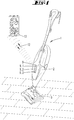
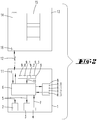
- a floor cleaning device 1 has a suction fan 2, which has an electric motor.
- a program-controlled electronic control device 6 which can be formed by a microcontroller or the like along with the periphery.
- a control panel 9 On the outside of the housing there is a control panel 9 with controls 9.0, 9.1, 9.2 and 9.3, each of which is a switch or button.
- a suction nozzle of the floor cleaning device 1 is inserted in a front attachment 3, which can have, for example, a brush roller driven by an electric motor.
- the reference number 5 designates control commands which the electronic control device 6 can emit to the electric motors of the suction fan 2 or of the front attachment 3 in order, for example, to specify their speed, their line intake or other operating parameters.
- a sensor 4 is provided with which the condition of the floor of the floor to be cleaned can be determined, for example.
- Sensor data 7 of the sensor 4 are transmitted to the electronic control device 6.
- the sensor 4 can be assigned in the suction device 2 or the attachment device 3. If the sensor 4 is assigned to the front attachment 3, a line connection can be provided between the front attachment 3 and the control device 6, with which the sensor data are transmitted.
- control elements 9.0, 9.1, 9.2 and 9.3 are connected to the electronic control device 6 via a data line.
- An operating specification can be entered via this data line. This is done by operating one or more of the controls 9.0, 9.1, 9.2 or 9.3.
- Configuration data 8.0, 8.1, 8.2, 8.3 are stored in a configuration memory 8, which are logical links between operating modes for operating the suction fan 2 or the front attachment 3 with an operating specification 10 individualized by the actuation of one of the operating elements 9.0 to 9.3.
- the actuation of one of the control elements 9.0 to 9.3 triggers a special operating specification 10.
- the links between this special operating specification 10 and a specific operating mode are stored in the configuration data 8.0 to 8.3.
- the operating mode assigned to it via the configuration data 8.0 to 8.3 is transmitted to the suction fan 2 or the front attachment 3.
- the suction fan 2 or the front attachment 3 is then operated, for example, in a limited power range.
- the configurations 8.1, 8.2, 8.3 stored in the configuration memory 8 can be changed by a data display and input device 13.
- the electronic control device 6 communicates via a communication interface 11 and a data transmission path 12 with a communication interface 16 of the data viewing and input device 13.
- This can be a WLAN connection, a connection via the mobile radio network or an individual, for example also wired, data transmission act.
- a screen of the data viewing and input device 13 shows the user a floor type catalog 14, in which typical floors to be cleaned are displayed, for example hard floors, carpets, wooden floors, etc.
- a suction parameter catalog 15 typical and / or optimal suction parameters or other operating parameters for the control of the suction blower or the front attachment is available, which the user can take over or change.
- the user can use a selection to determine a user-specific mode, how intensively he wants to clean which floors.
- predefined levels / positions of the operating elements 9.1, 9.2, 9.3 can be adapted and changed. Each control element thus forms an individual function button.
- the functions of the function buttons are preferably reprogrammed using an app on a mobile device.
- the operating parameters of this front-mounted device can be modified in a menu-controlled manner via inputs on the data display and input device 13.
- Parameters such as the cleaning intensity or the pushing force for the floor cleaning device 1 as such or the floor cleaning device 1 in combination with an attachment device 3 can be defined. These parameters can also be set for various different attachments.
- the user can also be shown the expected consequence of his preselected setting on the data display and input device 13, for example the cleaning quality, the volume, the handling or an accumulator runtime.
- the individual operating mode is preferably set using the floor detection sensor 4, which is an ultrasonic sensor, for example, and which is able to detect different floor types.
- This sensor can be assigned to the front device, so that the information is transmitted from the front device to the data display and input device 13 via the main device.
- the user can then make a desired setting for each and in particular for the current type of soil. Additional floor types can be selected via catalog 14 and individual settings assigned to them.
- the floor type catalog 14 presents all available floor types to the user and, with a suction parameter catalog 15, makes suggestions about cleaning profiles with which the respective floor type can be optimally cleaned. The user can accept these specifications or make modifications.
- a global routine is also possible, which derives the parameters determined from the soil to other soils, e.g. by recording the pushing forces for a soil type, which are then derived from other, similar soil types.
- the desired configurations are then transmitted to the electronic controller 6 via the data communication link 12, where they are stored in the configuration memory 8.
- the floor cleaning device controls its suction fan 2 or the front attachment 3 according to the individually stored configurations.
- the attachment 3 has its own control device 6, in which the configuration data can be stored.
- the reference number 9.0 can denote a main control element for switching on and off. It can also refer to an operating element with which the factory settings can be restored. Alternatively, however, it is also possible for reference number 9.0 to denote a separate control element, the actuation of which does not use the individual configuration, but rather a configuration of a factory setting.
- the factory setting can be stored in a main configuration 8, for example.
Landscapes
- Engineering & Computer Science (AREA)
- Mechanical Engineering (AREA)
- Electric Vacuum Cleaner (AREA)
Claims (10)
- Procédé pour faire fonctionner un appareil de nettoyage de sol (1), par exemple un aspirateur à main, avec au moins un moteur de nettoyage électrique (2) qui peut fonctionner dans différents modes de fonctionnement, avec un ou plusieurs éléments de commande (9.0, 9.1, 9.2, 9.3) pour l'entrée manuelle d'une consigne de fonctionnement (10) par l'utilisateur et avec un dispositif de commande électronique (6) dans lequel est mémorisée au moins une liaison logique de l'au moins une consigne de fonctionnement avec l'un des modes de fonctionnement, dans lequel l'au moins une liaison logique est modifiée par un dispositif universel de visualisation et d'entrée de données (13) relié au dispositif de nettoyage de sol (1) par une voie de transmission de données (12), caractérisé en ce que les modes de fonctionnement comprennent au moins : la qualité de nettoyage, une force de poussée en particulier minimale ou maximale pour déplacer le dispositif de nettoyage de sol (1) sur une surface de nettoyage, une section transversale de canal d'aspiration.
- Appareil de nettoyage de sol (1) pour la mise en œuvre du procédé mentionné dans la revendication 1, par exemple aspirateur à main, avec au moins un moteur de nettoyage électrique (2) qui peut fonctionner dans différents modes de fonctionnement, avec un ou plusieurs éléments de commande (9.0, 9.1, 9.2, 9.3) pour l'entrée manuelle d'une consigne de fonctionnement (10) par l'utilisateur, et avec un dispositif de commande électronique (6) dans lequel est mémorisée au moins une liaison logique de l'au moins une consigne de fonctionnement avec l'un des modes de fonctionnement, dans lequel l'au moins une liaison logique peut être modifiée au moyen d'un dispositif universel de visualisation et d'entrée de données (13) relié au dispositif de nettoyage de sol (1) par une voie de transmission de données (12), caractérisé en ce que les modes de fonctionnement comprennent au moins : la qualité de nettoyage, une force de poussée en particulier minimale ou maximale pour déplacer le dispositif de nettoyage de sol (1) sur une surface de nettoyage, une section transversale de canal d'aspiration.
- Procédé ou dispositif de nettoyage de sol selon l'une des revendications précédentes, caractérisé en ce que la voie de transmission de données (12) est une voie de transmission de données sans fil, en particulier une liaison WLAN ou de radiocommunication mobile, ou que la voie de transmission de données (12) est une liaison câblée, par exemple une liaison USB.
- Procédé ou dispositif de nettoyage de sol selon l'une des revendications précédentes, caractérisé en ce que le dispositif de nettoyage de sol (1) est intégré dans un réseau local, en particulier un réseau sans fil ou est intégré sans fil dans un réseau de radiocommunication mobile via l'Internet.
- Procédé ou dispositif de nettoyage de sol selon l'une des revendications précédentes, caractérisé en ce que le dispositif de visualisation et d'entrée de données (13) est un terminal mobile, en particulier un téléphone mobile, par exemple un smartphone.
- Procédé ou dispositif de nettoyage de sol selon l'une des revendications précédentes, caractérisé en ce que le moteur de nettoyage (2) entraîne un souffleur d'aspiration.
- Procédé ou dispositif de nettoyage de sol selon l'une des revendications précédentes, caractérisé en ce que le dispositif de nettoyage de sol (1) comprend un capteur de sol (4) avec lequel la nature du sol à nettoyer peut être déterminée, le capteur de sol (4) étant associé en particulier à un dispositif frontal (3).
- Procédé ou dispositif de nettoyage de sol selon l'une des revendications précédentes, caractérisé en ce que les propriétés du sol déterminées par le capteur de sol (4) sont transmises au dispositif de visualisation et d'entrée de données (13).
- Procédé ou dispositif de nettoyage de sol selon l'une des revendications précédentes, caractérisé en ce que le dispositif de visualisation et d'entrée de données (13) affiche un catalogue (14) de différents types de sol à l'intention de l'utilisateur, l'utilisateur pouvant sélectionner des paramètres d'aspiration spécifiques au type de sol dans un catalogue de paramètres d'aspiration (15).
- Procédé ou dispositif de nettoyage de sol selon l'une des revendications précédentes, caractérisé en ce qu'une configuration spécifique à l'utilisateur d'une mémoire de configuration (8), dans laquelle sont stockées les liaisons logiques modifiables, peut être ramenée à un réglage d'usine avec un élément de commande principal (9.0).
Applications Claiming Priority (1)
| Application Number | Priority Date | Filing Date | Title |
|---|---|---|---|
| DE102017116747.1A DE102017116747A1 (de) | 2017-07-25 | 2017-07-25 | Bodenreinigungsgerät und Verfahren zu dessen Betrieb |
Publications (2)
| Publication Number | Publication Date |
|---|---|
| EP3449792A1 EP3449792A1 (fr) | 2019-03-06 |
| EP3449792B1 true EP3449792B1 (fr) | 2020-04-29 |
Family
ID=62873229
Family Applications (1)
| Application Number | Title | Priority Date | Filing Date |
|---|---|---|---|
| EP18181671.1A Active EP3449792B1 (fr) | 2017-07-25 | 2018-07-04 | Appareil de nettoyage du sol et son procédé de fonctionnement |
Country Status (6)
| Country | Link |
|---|---|
| EP (1) | EP3449792B1 (fr) |
| JP (1) | JP2019025322A (fr) |
| CN (1) | CN109288446B (fr) |
| DE (1) | DE102017116747A1 (fr) |
| ES (1) | ES2799182T3 (fr) |
| TW (1) | TW201907846A (fr) |
Families Citing this family (9)
| Publication number | Priority date | Publication date | Assignee | Title |
|---|---|---|---|---|
| JP7253384B2 (ja) * | 2019-01-04 | 2023-04-06 | シャープ株式会社 | 電気掃除機 |
| DE102019106227A1 (de) * | 2019-03-12 | 2020-09-17 | Vorwerk & Co. Interholding Gmbh | Bodenbearbeitungsgerät und System aus einem Bodenbearbeitungsgerät und einem externen Endgerät |
| DE102019211014B4 (de) * | 2019-07-25 | 2024-07-18 | Vorwerk & Co. Interholding Gmbh | Haushaltsreinigungsgerät mit Akkuantrieb |
| TWI716957B (zh) * | 2019-08-07 | 2021-01-21 | 陳水石 | 清潔機器人及其材質辨識方法 |
| DE102020109111B4 (de) | 2020-04-01 | 2025-11-06 | Vorwerk & Co. Interholding Gesellschaft mit beschränkter Haftung | Verfahren zum Ermitteln mindestens eines Betriebsparameters eines handgeführten Haushaltsgeräts sowie Computerprogrammprodukt |
| WO2021238154A1 (fr) * | 2020-05-27 | 2021-12-02 | 莱克电气股份有限公司 | Procédé de commande pour dispositif de nettoyage, dispositif de nettoyage et support de stockage |
| DE102020211927B4 (de) * | 2020-09-23 | 2023-04-20 | BSH Hausgeräte GmbH | Verfahren zum Bearbeiten von Reinigungstätigkeiten und Reinigungskonfigurator |
| TWI779521B (zh) * | 2021-03-17 | 2022-10-01 | 旺玖科技股份有限公司 | 地板材質識別裝置以及具有該地板材質識別裝置的吸頭和吸塵器 |
| KR20250032465A (ko) * | 2023-08-31 | 2025-03-07 | 삼성전자주식회사 | 청소기 및 청소기의 동작 방법 |
Family Cites Families (17)
| Publication number | Priority date | Publication date | Assignee | Title |
|---|---|---|---|---|
| DE3041167A1 (de) * | 1980-10-31 | 1982-05-13 | Bosch-Siemens Hausgeräte GmbH, 7000 Stuttgart | Staubsauger mit regelung des unterdruckes zwischen dem staubfilter und dem saugwerkzeug |
| DE3603176C2 (de) * | 1986-02-03 | 1994-09-22 | Miele & Cie | Bedien- und Anzeigeeinheit für einen Staubsauger |
| KR100516315B1 (ko) * | 1997-08-25 | 2005-09-23 | 코닌클리케 필립스 일렉트로닉스 엔.브이. | 음향 표면 타입 검출기를 가진 전기적 표면 처리 장치 |
| CN1229069C (zh) * | 2002-01-06 | 2005-11-30 | 海尔集团公司 | 自动升降地板刷 |
| US7220930B2 (en) * | 2003-01-28 | 2007-05-22 | The Hoover Company | Floor care appliance with an electro luminescent switch panel |
| US7599758B2 (en) * | 2003-09-19 | 2009-10-06 | Royal Appliance Mfg. Co. | Sensors and associated methods for controlling a vacuum cleaner |
| US7823249B2 (en) * | 2006-01-05 | 2010-11-02 | The Scott Fetzer Company | Motor control for a vacuum cleaner |
| DE102012109627A1 (de) | 2012-10-10 | 2014-04-10 | Vorwerk & Co. Interholding Gmbh | Bodenreinigungsgerät |
| CN109965778B (zh) * | 2013-01-18 | 2022-08-16 | 艾罗伯特公司 | 包括移动机器人的环境管理系统以及其使用方法 |
| DE102013205661A1 (de) * | 2013-03-28 | 2014-10-02 | BSH Bosch und Siemens Hausgeräte GmbH | Bodenpflegegerät mit Energiesparfunktion |
| DK3003113T3 (en) * | 2013-05-28 | 2018-01-08 | Kaercher Gmbh & Co Kg Alfred | Method of setting a position of suction lips on a floor cleaner and floor cleaner |
| EP3087888B1 (fr) * | 2013-12-23 | 2019-08-14 | LG Electronics Inc. | Robot nettoyeur |
| DE102014110083A1 (de) | 2014-07-17 | 2016-01-21 | Vorwerk & Co. Interholding Gmbh | Verfahren zum Betrieb eines elektromotorisch angetriebenen Gerätes |
| DE102014110223A1 (de) * | 2014-07-21 | 2016-01-21 | Miele & Cie. Kg | Staubsauger mit einer Anzeigeeinrichtung und Anzeigeeinrichtung für einen Staubsauger |
| DE102015100977A1 (de) | 2015-01-23 | 2016-07-28 | Vorwerk & Co. Interholding Gmbh | Gerät zur Bearbeitung einer Oberfläche |
| DE102016118248A1 (de) | 2015-10-30 | 2017-05-04 | Vorwerk & Co. Interholding Gmbh | Reinigungsgerät, insbesondere Haushaltsstaubsauger |
| DE102016101040A1 (de) | 2016-01-21 | 2017-07-27 | Vorwerk & Co. Interholding Gmbh | Saugdüse für ein Saugreinigungsgerät |
-
2017
- 2017-07-25 DE DE102017116747.1A patent/DE102017116747A1/de not_active Withdrawn
-
2018
- 2018-07-04 EP EP18181671.1A patent/EP3449792B1/fr active Active
- 2018-07-04 ES ES18181671T patent/ES2799182T3/es active Active
- 2018-07-13 JP JP2018132931A patent/JP2019025322A/ja active Pending
- 2018-07-23 TW TW107125358A patent/TW201907846A/zh unknown
- 2018-07-25 CN CN201810827222.9A patent/CN109288446B/zh active Active
Non-Patent Citations (1)
| Title |
|---|
| None * |
Also Published As
| Publication number | Publication date |
|---|---|
| DE102017116747A1 (de) | 2019-01-31 |
| ES2799182T3 (es) | 2020-12-15 |
| EP3449792A1 (fr) | 2019-03-06 |
| CN109288446B (zh) | 2022-04-26 |
| TW201907846A (zh) | 2019-03-01 |
| JP2019025322A (ja) | 2019-02-21 |
| CN109288446A (zh) | 2019-02-01 |
Similar Documents
| Publication | Publication Date | Title |
|---|---|---|
| EP3449792A1 (fr) | Appareil de nettoyage du sol et son procédé de fonctionnement | |
| EP2741483B1 (fr) | Appareil de nettoyage automobile et procédé de fonctionnement d'un tel | |
| EP3440977A1 (fr) | Robot de nettoyage avec système de gestion des accumulateurs d'energie | |
| WO2006061133A1 (fr) | Robot de nettoyage | |
| EP3430701B1 (fr) | Appareil ménager et procédé de fonctionnement d'un appareil ménager | |
| EP4186403B1 (fr) | Système composé d'un appareil de traitement du sol, d'un dispositif accumulateur et d'au moins un appareil accessoire | |
| EP3243418B1 (fr) | Système et procédé de nettoyage d'un plancher à l'aide d'un robot de nettoyage | |
| EP3995065B1 (fr) | Appareil de nettoyage autonome | |
| EP2753164A1 (fr) | Engin de travail autonome | |
| DE102016113579A1 (de) | Adapteranordnungssystem | |
| EP3454715A1 (fr) | Système et procédé de nettoyage d'un sol avec un robot de nettoyage | |
| EP3162266A1 (fr) | Reinigungsgerät und verfahren zum betrieb eines reinigungsgerätes | |
| EP4394571A2 (fr) | Système de nettoyage à haute pression et procédé permettant de faire fonctionner un système de nettoyage à haute pression | |
| DE102018126103A1 (de) | Saugreinigungsgerät mit einem Influenzsensor | |
| EP3162263B1 (fr) | Appareil de nettoyage et appareil auxiliaire destiné à relier un appareil de base de l'appareil de nettoyage | |
| EP2691003B1 (fr) | Procédé pour faire fonctionner un aspirateur en fonction de la pression d'aspiration | |
| EP4098162B1 (fr) | Procédé de réglage d'une plage de paramètres sur un appareil de traitement du sol, ainsi qu'appareil de traitement du sol et système doté d'un appareil de traitement du sol et d'un terminal externe | |
| EP2783618A2 (fr) | Appareil d'entretien du sol dotée d'une fonction d'économie d'énergie | |
| EP3821778B1 (fr) | Aspirateur et procédé de fonctionnement d'un aspirateur | |
| DE102019106292A1 (de) | Bodenbearbeitungsgerät mit einem Akkumulator und System aus einem Bodenbearbeitungsgerät und mindestens einem weiteren Akkumulator | |
| DE102012112403A1 (de) | Akkumulatorbetriebenes Reinigungsgerät sowie Verfahren zur Bestimmung des Alterungszustandes eines Akkumulators | |
| EP4137026B1 (fr) | Procédé de fonctionnement d'un appareil de nettoyage, ainsi que appareil de nettoyage | |
| EP3973840B1 (fr) | Procédé de traitement des activités de nettoyage | |
| EP4434422B1 (fr) | Procédé de fonctionnement d'un appareil de nettoyage automoteur et appareil de nettoyage automoteur | |
| EP4205615A1 (fr) | Système de nettoyage composé d'un appareil de base et d'au moins un accessoire |
Legal Events
| Date | Code | Title | Description |
|---|---|---|---|
| PUAI | Public reference made under article 153(3) epc to a published international application that has entered the european phase |
Free format text: ORIGINAL CODE: 0009012 |
|
| STAA | Information on the status of an ep patent application or granted ep patent |
Free format text: STATUS: THE APPLICATION HAS BEEN PUBLISHED |
|
| AK | Designated contracting states |
Kind code of ref document: A1 Designated state(s): AL AT BE BG CH CY CZ DE DK EE ES FI FR GB GR HR HU IE IS IT LI LT LU LV MC MK MT NL NO PL PT RO RS SE SI SK SM TR |
|
| AX | Request for extension of the european patent |
Extension state: BA ME |
|
| STAA | Information on the status of an ep patent application or granted ep patent |
Free format text: STATUS: REQUEST FOR EXAMINATION WAS MADE |
|
| 17P | Request for examination filed |
Effective date: 20190828 |
|
| RBV | Designated contracting states (corrected) |
Designated state(s): AL AT BE BG CH CY CZ DE DK EE ES FI FR GB GR HR HU IE IS IT LI LT LU LV MC MK MT NL NO PL PT RO RS SE SI SK SM TR |
|
| GRAP | Despatch of communication of intention to grant a patent |
Free format text: ORIGINAL CODE: EPIDOSNIGR1 |
|
| STAA | Information on the status of an ep patent application or granted ep patent |
Free format text: STATUS: GRANT OF PATENT IS INTENDED |
|
| RIC1 | Information provided on ipc code assigned before grant |
Ipc: A47L 9/28 20060101AFI20191030BHEP |
|
| INTG | Intention to grant announced |
Effective date: 20191121 |
|
| GRAS | Grant fee paid |
Free format text: ORIGINAL CODE: EPIDOSNIGR3 |
|
| GRAA | (expected) grant |
Free format text: ORIGINAL CODE: 0009210 |
|
| STAA | Information on the status of an ep patent application or granted ep patent |
Free format text: STATUS: THE PATENT HAS BEEN GRANTED |
|
| AK | Designated contracting states |
Kind code of ref document: B1 Designated state(s): AL AT BE BG CH CY CZ DE DK EE ES FI FR GB GR HR HU IE IS IT LI LT LU LV MC MK MT NL NO PL PT RO RS SE SI SK SM TR |
|
| REG | Reference to a national code |
Ref country code: GB Ref legal event code: FG4D Free format text: NOT ENGLISH |
|
| REG | Reference to a national code |
Ref country code: CH Ref legal event code: EP |
|
| REG | Reference to a national code |
Ref country code: AT Ref legal event code: REF Ref document number: 1262065 Country of ref document: AT Kind code of ref document: T Effective date: 20200515 |
|
| REG | Reference to a national code |
Ref country code: DE Ref legal event code: R096 Ref document number: 502018001317 Country of ref document: DE |
|
| REG | Reference to a national code |
Ref country code: IE Ref legal event code: FG4D Free format text: LANGUAGE OF EP DOCUMENT: GERMAN |
|
| PGFP | Annual fee paid to national office [announced via postgrant information from national office to epo] |
Ref country code: CZ Payment date: 20200625 Year of fee payment: 3 |
|
| REG | Reference to a national code |
Ref country code: NL Ref legal event code: MP Effective date: 20200429 |
|
| REG | Reference to a national code |
Ref country code: LT Ref legal event code: MG4D |
|
| PG25 | Lapsed in a contracting state [announced via postgrant information from national office to epo] |
Ref country code: PT Free format text: LAPSE BECAUSE OF FAILURE TO SUBMIT A TRANSLATION OF THE DESCRIPTION OR TO PAY THE FEE WITHIN THE PRESCRIBED TIME-LIMIT Effective date: 20200831 Ref country code: IS Free format text: LAPSE BECAUSE OF FAILURE TO SUBMIT A TRANSLATION OF THE DESCRIPTION OR TO PAY THE FEE WITHIN THE PRESCRIBED TIME-LIMIT Effective date: 20200829 Ref country code: GR Free format text: LAPSE BECAUSE OF FAILURE TO SUBMIT A TRANSLATION OF THE DESCRIPTION OR TO PAY THE FEE WITHIN THE PRESCRIBED TIME-LIMIT Effective date: 20200730 Ref country code: SE Free format text: LAPSE BECAUSE OF FAILURE TO SUBMIT A TRANSLATION OF THE DESCRIPTION OR TO PAY THE FEE WITHIN THE PRESCRIBED TIME-LIMIT Effective date: 20200429 Ref country code: LT Free format text: LAPSE BECAUSE OF FAILURE TO SUBMIT A TRANSLATION OF THE DESCRIPTION OR TO PAY THE FEE WITHIN THE PRESCRIBED TIME-LIMIT Effective date: 20200429 Ref country code: FI Free format text: LAPSE BECAUSE OF FAILURE TO SUBMIT A TRANSLATION OF THE DESCRIPTION OR TO PAY THE FEE WITHIN THE PRESCRIBED TIME-LIMIT Effective date: 20200429 Ref country code: NO Free format text: LAPSE BECAUSE OF FAILURE TO SUBMIT A TRANSLATION OF THE DESCRIPTION OR TO PAY THE FEE WITHIN THE PRESCRIBED TIME-LIMIT Effective date: 20200729 |
|
| PG25 | Lapsed in a contracting state [announced via postgrant information from national office to epo] |
Ref country code: BG Free format text: LAPSE BECAUSE OF FAILURE TO SUBMIT A TRANSLATION OF THE DESCRIPTION OR TO PAY THE FEE WITHIN THE PRESCRIBED TIME-LIMIT Effective date: 20200729 Ref country code: LV Free format text: LAPSE BECAUSE OF FAILURE TO SUBMIT A TRANSLATION OF THE DESCRIPTION OR TO PAY THE FEE WITHIN THE PRESCRIBED TIME-LIMIT Effective date: 20200429 Ref country code: RS Free format text: LAPSE BECAUSE OF FAILURE TO SUBMIT A TRANSLATION OF THE DESCRIPTION OR TO PAY THE FEE WITHIN THE PRESCRIBED TIME-LIMIT Effective date: 20200429 Ref country code: HR Free format text: LAPSE BECAUSE OF FAILURE TO SUBMIT A TRANSLATION OF THE DESCRIPTION OR TO PAY THE FEE WITHIN THE PRESCRIBED TIME-LIMIT Effective date: 20200429 |
|
| REG | Reference to a national code |
Ref country code: ES Ref legal event code: FG2A Ref document number: 2799182 Country of ref document: ES Kind code of ref document: T3 Effective date: 20201215 |
|
| PG25 | Lapsed in a contracting state [announced via postgrant information from national office to epo] |
Ref country code: AL Free format text: LAPSE BECAUSE OF FAILURE TO SUBMIT A TRANSLATION OF THE DESCRIPTION OR TO PAY THE FEE WITHIN THE PRESCRIBED TIME-LIMIT Effective date: 20200429 Ref country code: NL Free format text: LAPSE BECAUSE OF FAILURE TO SUBMIT A TRANSLATION OF THE DESCRIPTION OR TO PAY THE FEE WITHIN THE PRESCRIBED TIME-LIMIT Effective date: 20200429 |
|
| PG25 | Lapsed in a contracting state [announced via postgrant information from national office to epo] |
Ref country code: EE Free format text: LAPSE BECAUSE OF FAILURE TO SUBMIT A TRANSLATION OF THE DESCRIPTION OR TO PAY THE FEE WITHIN THE PRESCRIBED TIME-LIMIT Effective date: 20200429 Ref country code: SM Free format text: LAPSE BECAUSE OF FAILURE TO SUBMIT A TRANSLATION OF THE DESCRIPTION OR TO PAY THE FEE WITHIN THE PRESCRIBED TIME-LIMIT Effective date: 20200429 Ref country code: DK Free format text: LAPSE BECAUSE OF FAILURE TO SUBMIT A TRANSLATION OF THE DESCRIPTION OR TO PAY THE FEE WITHIN THE PRESCRIBED TIME-LIMIT Effective date: 20200429 Ref country code: RO Free format text: LAPSE BECAUSE OF FAILURE TO SUBMIT A TRANSLATION OF THE DESCRIPTION OR TO PAY THE FEE WITHIN THE PRESCRIBED TIME-LIMIT Effective date: 20200429 |
|
| REG | Reference to a national code |
Ref country code: DE Ref legal event code: R097 Ref document number: 502018001317 Country of ref document: DE |
|
| PG25 | Lapsed in a contracting state [announced via postgrant information from national office to epo] |
Ref country code: PL Free format text: LAPSE BECAUSE OF FAILURE TO SUBMIT A TRANSLATION OF THE DESCRIPTION OR TO PAY THE FEE WITHIN THE PRESCRIBED TIME-LIMIT Effective date: 20200429 Ref country code: MC Free format text: LAPSE BECAUSE OF FAILURE TO SUBMIT A TRANSLATION OF THE DESCRIPTION OR TO PAY THE FEE WITHIN THE PRESCRIBED TIME-LIMIT Effective date: 20200429 Ref country code: SK Free format text: LAPSE BECAUSE OF FAILURE TO SUBMIT A TRANSLATION OF THE DESCRIPTION OR TO PAY THE FEE WITHIN THE PRESCRIBED TIME-LIMIT Effective date: 20200429 |
|
| PLBE | No opposition filed within time limit |
Free format text: ORIGINAL CODE: 0009261 |
|
| STAA | Information on the status of an ep patent application or granted ep patent |
Free format text: STATUS: NO OPPOSITION FILED WITHIN TIME LIMIT |
|
| 26N | No opposition filed |
Effective date: 20210201 |
|
| REG | Reference to a national code |
Ref country code: BE Ref legal event code: MM Effective date: 20200731 |
|
| PG25 | Lapsed in a contracting state [announced via postgrant information from national office to epo] |
Ref country code: LU Free format text: LAPSE BECAUSE OF NON-PAYMENT OF DUE FEES Effective date: 20200704 Ref country code: IE Free format text: LAPSE BECAUSE OF NON-PAYMENT OF DUE FEES Effective date: 20200704 |
|
| PG25 | Lapsed in a contracting state [announced via postgrant information from national office to epo] |
Ref country code: SI Free format text: LAPSE BECAUSE OF FAILURE TO SUBMIT A TRANSLATION OF THE DESCRIPTION OR TO PAY THE FEE WITHIN THE PRESCRIBED TIME-LIMIT Effective date: 20200429 Ref country code: BE Free format text: LAPSE BECAUSE OF NON-PAYMENT OF DUE FEES Effective date: 20200731 |
|
| PG25 | Lapsed in a contracting state [announced via postgrant information from national office to epo] |
Ref country code: CZ Free format text: LAPSE BECAUSE OF NON-PAYMENT OF DUE FEES Effective date: 20210704 |
|
| REG | Reference to a national code |
Ref country code: CH Ref legal event code: PL |
|
| PG25 | Lapsed in a contracting state [announced via postgrant information from national office to epo] |
Ref country code: LI Free format text: LAPSE BECAUSE OF NON-PAYMENT OF DUE FEES Effective date: 20210731 Ref country code: CH Free format text: LAPSE BECAUSE OF NON-PAYMENT OF DUE FEES Effective date: 20210731 |
|
| PG25 | Lapsed in a contracting state [announced via postgrant information from national office to epo] |
Ref country code: TR Free format text: LAPSE BECAUSE OF FAILURE TO SUBMIT A TRANSLATION OF THE DESCRIPTION OR TO PAY THE FEE WITHIN THE PRESCRIBED TIME-LIMIT Effective date: 20200429 Ref country code: MT Free format text: LAPSE BECAUSE OF FAILURE TO SUBMIT A TRANSLATION OF THE DESCRIPTION OR TO PAY THE FEE WITHIN THE PRESCRIBED TIME-LIMIT Effective date: 20200429 Ref country code: CY Free format text: LAPSE BECAUSE OF FAILURE TO SUBMIT A TRANSLATION OF THE DESCRIPTION OR TO PAY THE FEE WITHIN THE PRESCRIBED TIME-LIMIT Effective date: 20200429 |
|
| PG25 | Lapsed in a contracting state [announced via postgrant information from national office to epo] |
Ref country code: MK Free format text: LAPSE BECAUSE OF FAILURE TO SUBMIT A TRANSLATION OF THE DESCRIPTION OR TO PAY THE FEE WITHIN THE PRESCRIBED TIME-LIMIT Effective date: 20200429 |
|
| GBPC | Gb: european patent ceased through non-payment of renewal fee |
Effective date: 20220704 |
|
| PG25 | Lapsed in a contracting state [announced via postgrant information from national office to epo] |
Ref country code: GB Free format text: LAPSE BECAUSE OF NON-PAYMENT OF DUE FEES Effective date: 20220704 |
|
| P01 | Opt-out of the competence of the unified patent court (upc) registered |
Effective date: 20230517 |
|
| REG | Reference to a national code |
Ref country code: AT Ref legal event code: MM01 Ref document number: 1262065 Country of ref document: AT Kind code of ref document: T Effective date: 20230704 |
|
| PG25 | Lapsed in a contracting state [announced via postgrant information from national office to epo] |
Ref country code: AT Free format text: LAPSE BECAUSE OF NON-PAYMENT OF DUE FEES Effective date: 20230704 |
|
| PG25 | Lapsed in a contracting state [announced via postgrant information from national office to epo] |
Ref country code: AT Free format text: LAPSE BECAUSE OF NON-PAYMENT OF DUE FEES Effective date: 20230704 |
|
| PGFP | Annual fee paid to national office [announced via postgrant information from national office to epo] |
Ref country code: ES Payment date: 20250819 Year of fee payment: 8 |
|
| PGFP | Annual fee paid to national office [announced via postgrant information from national office to epo] |
Ref country code: DE Payment date: 20250722 Year of fee payment: 8 |
|
| PGFP | Annual fee paid to national office [announced via postgrant information from national office to epo] |
Ref country code: IT Payment date: 20250731 Year of fee payment: 8 |
|
| PGFP | Annual fee paid to national office [announced via postgrant information from national office to epo] |
Ref country code: FR Payment date: 20250723 Year of fee payment: 8 |
|
| PGFP | Annual fee paid to national office [announced via postgrant information from national office to epo] |
Ref country code: AT Payment date: 20260410 Year of fee payment: 5 |