EP3449794A1 - Dispositif de nettoyage doté d'une plaque oscillante à entraînement par moteur - Google Patents
Dispositif de nettoyage doté d'une plaque oscillante à entraînement par moteur Download PDFInfo
- Publication number
- EP3449794A1 EP3449794A1 EP18184640.3A EP18184640A EP3449794A1 EP 3449794 A1 EP3449794 A1 EP 3449794A1 EP 18184640 A EP18184640 A EP 18184640A EP 3449794 A1 EP3449794 A1 EP 3449794A1
- Authority
- EP
- European Patent Office
- Prior art keywords
- plate
- cleaning device
- support plate
- latching
- oscillating
- Prior art date
- Legal status (The legal status is an assumption and is not a legal conclusion. Google has not performed a legal analysis and makes no representation as to the accuracy of the status listed.)
- Granted
Links
Images


Classifications
-
- A—HUMAN NECESSITIES
- A47—FURNITURE; DOMESTIC ARTICLES OR APPLIANCES; COFFEE MILLS; SPICE MILLS; SUCTION CLEANERS IN GENERAL
- A47L—DOMESTIC WASHING OR CLEANING; SUCTION CLEANERS IN GENERAL
- A47L11/00—Machines for cleaning floors, carpets, furniture, walls, or wall coverings
- A47L11/28—Floor-scrubbing machines, motor-driven
-
- A—HUMAN NECESSITIES
- A47—FURNITURE; DOMESTIC ARTICLES OR APPLIANCES; COFFEE MILLS; SPICE MILLS; SUCTION CLEANERS IN GENERAL
- A47L—DOMESTIC WASHING OR CLEANING; SUCTION CLEANERS IN GENERAL
- A47L11/00—Machines for cleaning floors, carpets, furniture, walls, or wall coverings
- A47L11/02—Floor surfacing or polishing machines
- A47L11/04—Floor surfacing or polishing machines hand-driven
- A47L11/06—Floor surfacing or polishing machines hand-driven with reciprocating or oscillating tools
-
- A—HUMAN NECESSITIES
- A47—FURNITURE; DOMESTIC ARTICLES OR APPLIANCES; COFFEE MILLS; SPICE MILLS; SUCTION CLEANERS IN GENERAL
- A47L—DOMESTIC WASHING OR CLEANING; SUCTION CLEANERS IN GENERAL
- A47L11/00—Machines for cleaning floors, carpets, furniture, walls, or wall coverings
- A47L11/02—Floor surfacing or polishing machines
- A47L11/10—Floor surfacing or polishing machines motor-driven
- A47L11/12—Floor surfacing or polishing machines motor-driven with reciprocating or oscillating tools
-
- A—HUMAN NECESSITIES
- A47—FURNITURE; DOMESTIC ARTICLES OR APPLIANCES; COFFEE MILLS; SPICE MILLS; SUCTION CLEANERS IN GENERAL
- A47L—DOMESTIC WASHING OR CLEANING; SUCTION CLEANERS IN GENERAL
- A47L11/00—Machines for cleaning floors, carpets, furniture, walls, or wall coverings
- A47L11/40—Parts or details of machines not provided for in groups A47L11/02 - A47L11/38, or not restricted to one of these groups, e.g. handles, arrangements of switches, skirts, buffers, levers
- A47L11/4036—Parts or details of the surface treating tools
Definitions
- the invention relates to a cleaning device, in particular for a wet cleaning device, with a motor-driven swing plate and connectable to the swing plate support plate for receiving a cleaning element, wherein the swing plate and the support plate, based on an interconnected state, on facing plate sides corresponding fasteners, wherein a fastening means of the oscillating plate and a fastening means of the support plate form a pair of fasteners and wherein, moreover, the fastener pair on the one hand against a restoring force of a spring element displaceable latching element, and on the other hand has an undercut exhibiting receiving element for receiving the latching element.
- the invention relates to a wet cleaning device with such a cleaning device.
- the cleaning devices are used in particular for the cleaning of hard floor coverings, such as tile floors or parquet floors, especially in the household sector.
- the cleaning devices can be designed, for example, as attachments for detachable connection to a base unit.
- the base unit in particular provides a device for pushing the cleaning device over a surface to be cleaned, an electrical supply, optionally in addition a suction fan, and further available.
- the cleaning devices have a cleaning element acting on a surface to be cleaned, for example in the form of a textile cleaning cloth.
- the cleaning element is oscillated by means of a vibrating plate, whereby a sliding displacement (forward and backward displacement) performed by a user of the cleaning device during a usual cleaning operation is superimposed by the movement of the vibrating plate and thus also the movement of the cleaning element.
- the cleaning element is mounted on a support plate, which in turn can be arranged on the swing plate so that the support plate is firmly connected to the swing plate and the swinging movement along.
- the vibrating plate is rotated for example
- the publication EP 2 578 131 B1 known.
- the carrier plate and the oscillating plate have corresponding mounting rails.
- To connect the fixing rails it is necessary for a user to lift the cleaning device from a surface to be cleaned and to push the support plate onto the swinging plate parallel to an extension plane of the swinging plate. It is necessary that the user guides the carrier plate with his hand.
- cleaning devices which provide a pair of fasteners with a locking element and a receiving element.
- the DE 10 2010 000 378 A1 discloses, for example, a cleaning device having a motor-driven oscillating plate and a carrier plate connectable thereto, the oscillating plate and the carrier plate having corresponding fastening means, one of which forms a spring-loaded detent element and the other a receptacle for the detent element.
- the fasteners are latched together by a portion of the vibrating plate is pushed substantially parallel to a large surface plane thereof laterally on the support plate until it comes to one side of the aforementioned latching.
- the invention proposes that in a plan view of the facing plate sides on a plate side, an end portion of the locking element and on the other side of the plate insertion of the locking element to the fastener pair complementary receiving element exposed and that in a mutually attached state of the vibrating plate and the support plate in a vertical section perpendicular to a swing plane of the swing plate, the receiving element surrounds the latching element on the outside.
- the carrier plate By means of the invention, it is no longer necessary for the carrier plate to be attached to the oscillating plate so that a user grips the carrier plate with his hand and pushes it onto the oscillating plate. Rather, it is now possible to connect the support plate by means of the spring-loaded locking elements with the swinging plate, wherein the restoring force of the locking elements is overcome by a force exerted by the user, for example, by pressing the swing plate on the carrier plate located on the surface to be cleaned.
- the user advantageously places the cleaning device over the carrier plate such that the oscillating plate rests above the carrier plate to be connected and both are aligned parallel to one another with respect to their longitudinal extent.
- additional arrangement means can be predetermined, which simplify a relative adjustment of the vibrating plate and the support plate to each other.
- the user guides the fastening means of the oscillating plate over the fastening means of the support plate and presses them together until the latching element snaps behind the undercut of the receiving element.
- the restoring force of the spring element is first overcome for the displacement of the locking element, and then - if the locking element is engaged behind the undercut - the locking element at least partially shifted back in the direction of the restoring force, so that the locking element firmly engages behind the undercut and thus optimal, particular backlash, compound of the vibrating plate and the support plate causes each other.
- the support plate performs the same movement as the vibrating plate, that is, during a cleaning operation, for example, the typical swinging motion over the surface to be cleaned.
- the invention is in a plan view of the facing plate sides on the one hand an end portion of the locking element, and on the other hand, an insertion of the receiving element, which receives the locking element, free.
- the cleaning device has only a single pair of fasteners.
- the carrier plate is detachable or latchable to the vibrating plate only at a certain connection point between the carrier plate and the vibrating plate by a spring-loaded latching element.
- the cleaning device has a plurality of fastener pairs, a spring-assisted latching or unlocking of the support plate on several sides of the cleaning device is possible.
- the fastener pairs are in relation to a circumferential direction of the support plate or the vibrating plate opposite.
- Each of the fastener pairs has at least one spring-loaded latching element, which serves for joining and releasing the support plate relative to the vibration plate.
- the joining and releasing force of the locking element can be adjusted via the restoring force of the spring element and the latching curve of the undercut. Overall, results in a robust, inexpensive and tolerances insensitive connection of vibrating plate and carrier plate, which allows frequent loosening and reconnecting.
- the spring element associated with the detent element is a torsion spring.
- the torsion spring also called leg spring, engages with an end portion on a base of the swing plate or the support plate on, and with an opposite end region on the latching element of the vibrating plate or carrier plate.
- the restoring force of the spring element is directed in the direction of the locking position of the locking element.
- the spring element may also be a leaf spring, coil spring, worm spring or the like.
- the latching element and the spring element are integrally formed.
- the latching element and the spring element may be formed as a resilient latching element.
- the locking element may be, for example, a leaf spring, which is formed at the end as a locking means.
- the locking element may be formed of a resilient material and having a molded latching hook, a latching nose or the like. With this configuration, the number of components used for the latching mechanism is particularly low.
- a free end region of the latching element has a rotatably mounted rotational element which rotates upon connection of the latching element and the receiving element.
- the rotation element can be, for example, a roller element arranged on an end region of the latching element, which rolls on the receiving element during latching. As a result, the friction between the locking element and the receiving element is minimized because the locking element no longer grinds along the receiving element to get behind the undercut. This design is also particularly wear-resistant.
- the rotation element is mounted for example on a rotational axis of the latching element, which rotation axis is preferably perpendicular to the latching direction.
- the oscillating plate and the carrier plate at least two pairs of fasteners have, wherein two pairs of fasteners are arranged with respect to a longitudinal extent of the vibrating plate or support plate at opposite end portions of the vibrating plate or support plate.
- the two pairs of fasteners are preferably located in the same plane parallel to a plane of vibration of the oscillating plate or the carrier plate.
- the pairs of fasteners are based on the longitudinal extent of the vibrating plate or support plate as far apart as possible, so that results in a release of one of the fastener pairs by unilateral displacement of the support plate against the vibrating plate as large a lever.
- a still latched locking means of a corresponding second fastener pair due to a restoring force of an associated spring element has a remaining bias, so that the support plate and the vibrating plate are automatically separated.
- the latching element along and relative to a linear or arcuate guide means of the swing plate or support plate is displaced.
- the locking element runs during a displacement movement along the guide means, whereby - depending on the shape of the guide means - a traversed either linear or arcuate displacement track.
- the guide means may for example be a guide slot within which runs at least a portion of the locking element.
- This guide device is straight or curved and defines the direction of movement of the locking element. This direction of movement influences the joining or releasing force, which is required for joining or separating the pair of fasteners. This is partly due to the displacement direction of the locking element relative to the direction of gravity, and on the other hand by a friction surface between the locking element and the corresponding receiving element.
- the displacement path of the guide device can also be influenced by the type of Be determined spring element, in particular by the direction of action of the spring element.
- the spring element is at least partially tensioned when latched with the receiving element state of the locking element.
- the spring element in the latched state of the locking element to a bias, which supports the ejection of the carrier plate upon release of the carrier plate of the vibrating plate.
- the release of the support plate is particularly simple and in particular without manual gripping of the support plate or the swing plate by the user possible.
- the cleaning device has a spring-loaded pair of fasteners and a rigid pair of fasteners, the pivoting of the support plate or swing plate about a pivot center of the rigid fastener pair, so that the bias of the spring element of the other fastener pair leads to a supported release of the spring-loaded locking element from the corresponding receiving element.
- the latching element is arranged on the oscillating plate, and that the receiving element is arranged on the carrier plate.
- the movable locking element is located on the vibrating plate, which usually remains on the cleaning device.
- the support plate which is designed to accommodate the cleaning element, however, is particularly simple and designed without moving elements. In principle, however, it is also possible that the locking element is arranged on the support plate, and that the receiving element is formed on the oscillating plate.
- a fastening element pair is associated with an actuating element, which is displaceable as a result of actuation against the carrier plate in order to release it from the oscillating plate.
- the actuating element can, for example, be an actuating element which can be pivoted about an axis and which can be swiveled by the user through a step onto an actuating region on the upper side of the housing of the cleaning device.
- the operation is preferably only in a sacking position of the cleaning device, that is in a relative to a surface to be cleaned pivoted position of the cleaning device, and thus also the vibrating plate and the carrier plate, possible.
- the release of the support plate of the swing plate is possible only when the cleaning device, that is with the engine off, in the sack truck position.
- the Sackkarrenraum corresponds to a transport position in which the cleaning device is tilted on arranged on a device trailing edge rollers. In this position, the support plate with a possibly arranged thereon cleaning element is sufficiently lifted from the surface to be cleaned in order to solve the support plate of the vibrating plate can.
- the separation of the fastening means of a pair of fasteners is then carried out by a force which acts against the support plate, preferably against a peripheral edge of the support plate.
- the actuating element is supported for introducing the force against a housing of the cleaning device, namely preferably against the aforementioned operating range.
- the actuating element is preferably part of a rocker mechanism, which acts on actuation of the actuating region and thus pivoting of the actuating element against the carrier plate.
- electrical or other mechanically actuated actuators are possible.
- the invention also proposes a wet cleaning device having such a cleaning device.
- the wet cleaning device can basically be any cleaning device that can perform a wet cleaning exclusively or among other things. These include, on the one hand hand-held wet cleaning equipment, but also automatically movable wet cleaning equipment, in particular cleaning robot. In addition, combined dry and wet cleaning devices are included.
- wet cleaning equipment for cleaning overground surfaces includes, for example, for cleaning windows, shelves, baseboards, steps and the like.
- FIG. 1 shows a wet cleaning device 2, which is equipped here as a hand-held wet cleaning device 2 with a base unit 17 and designed as a front attachment cleaning device 1.
- the cleaning device 1 is detachably held on the base unit 17.
- the base unit 17 has a handle 18, which is designed here, for example, telescopic, so that a user of the wet cleaning device 2 can adjust the length of the handle 18 to its body size.
- a handle 19 on which the user guides the wet cleaning device 2 during a typical wiping operation, that is to say sliding over a surface to be cleaned, is arranged on the handle 18.
- the user usually carries the wet cleaning device 2 in opposite directions of movement over the surface to be cleaned.
- a switch 20 is arranged, which can serve for example to turn on and off a motor of the wet cleaning device 2.
- the motor is powered by an electric cable 16 of the wet cleaning device 2 with energy.
- an actuating region 15 is formed, namely here a tread surface over which a user of the cleaning device 1 can solve a support plate 4 with a cleaning element 5 of a vibrating plate 3 of the cleaning device 1.
- the cleaning device 1 has the in FIG. 2 shown combination of a swing plate 3, a support plate 4 and a cleaning element 5 on.
- the oscillating plate 3 has on its upper side shown centrally on a rotational axis recording 22 for a drive axle of the engine.
- the drive shaft is used in combination with an eccentric on the one hand for fixing the oscillating plate 3 to the cleaning device 1, and on the other hand for causing oscillating oscillatory movements of the vibrating plate 3.
- the eccentric drive of the vibrating plate 3 is further to the publication EP 2 578 131 A1 directed.
- the vibrating plate 3 is preferably driven at an oscillation frequency of, for example, 1000 rpm up to 2000 rpm.
- This oscillatory movement of the oscillating plate 3 relative to a housing of the cleaning device 1 is superimposed during a wiping operation with a displacement of the wet cleaning device 2 over the surface to be cleaned by a user.
- Both movements that is to say both the manual displacement movement and the oscillatory movement of the oscillating plate 3, take place in the same plane, namely the plane of oscillation of the oscillating plate 3.
- the cleaning element 5 is a partially elastic trained cleaning cloth, in particular a microfiber cloth. This can be fastened with the aid of cleaning element fastenings 21, here Velcro fasteners, on corresponding cleaning element fastenings (not shown) of the support plate 4.
- the attachment means 6 of the swing plate 3 is a relative to the swing plate 3 displaceable latching element 11 having a free end portion 27.
- the latching element 11 is within a Guide device 14 guided and acted upon by the restoring force of a spring element 10.
- the guide device 14 is here designed according to the type of a guide slot, within which the latching element 11 is held linearly displaceable.
- the carrier plate 4 has, corresponding to the attachment means 6 of the oscillating plate 3, a receiving element 13 having an insertion bevel 28 and an undercut 12.
- the attachment means 6, 7 of the swing plate 3 and the support plate 4 are so far formed corresponding to each other, as the locking element 11 of the swing plate 3 slides in connection with the support plate 4 on the insertion bevel 28 of the receiving element 13 and finally the contour of the receiving element 13 following behind the Undercut 12 engages.
- the restoring force of the spring element 10 acts against the receiving element 13.
- the locking element 11 performs a linear movement within the guide device 14. When the latching connection is opened, the latching element 11 tends to move in the direction of a plate center, ie away from the receiving element 13.
- the latching element 11 When closing the locking element 11 moves after overcoming the insertion bevel 28 in the opposite direction of movement within the guide device 14, namely to the outside.
- the latching element 11 it would also be possible for the latching element 11 to run on an arcuate path of a guide slot.
- at least one locking element 11 has a permanent bias.
- the other, still latched locking element 11 has a remaining bias, which leads to the automatic separation of carrier plate 4 and vibrating plate 3.
- the locking elements 11 perform opposite movements. When you open the locking connection, the locking elements 11 move toward each other, while these move away from each other when closing the locking connection, so in each case in opposite directions of movement.
- the oscillating plate 3 and the carrier plate 4 also have corresponding centering means 23, 24 and centering receivers 25 (see FIG. 3 ) on.
- the centering means 23, 24 are formed on the support plate 4 projections, which can engage in the centering 25 of the vibrating plate 3.
- one of the centering receivers 25 is designed such that there is a range of motion in at least one direction of movement for the centering means 23, 24 located therein.
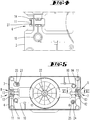
- FIG. 3 shows a bottom of the swing plate 3.
- the illustrated side of the swing plate 3 is the one that faces the support plate 4 in the connected state of support plate 4 and swing plate 3.
- One of the centering receptacles 25 in this case has an inner contour which has the same diameter as an outer contour of the centering means 23, 24, so that the centering means 23, 24 can be held without play within this centering receptacle 25.
- the second centering receptacle 25 has, relative to a spatial direction, a greater length than the diameter of the centering means 23, 24, so that in principle there is a range of motion for the centering means 23, 24 accommodated within this centering receptacle 25. By this range of motion tilting during joining or detachment of the swing plate 3 and support plate 4 is prevented.
- the centering means 23, 24 of the support plate 4 and the centering 25 of the vibrating plate 3 are arranged point-symmetrical relative to the rotation axis recording 22, so that the support plate 4 can be fixed with two different orientations on the vibrating plate 3, namely with two 180 ° about the axis of rotation 22 rotated Orientations.
- the vibration plate 3 is shown without arranged thereon carrier plate 4.
- the spring element 10 here is a torsion spring, which is fastened with one leg to the housing of the oscillating plate 3 and with the other leg to the latching element 11.
- FIG. 4 shows an enlarged portion of the vibrating plate 3 with latching element 11 arranged thereon.
- FIG. 5 shows a section through the swing plate 3 in a state connected to the support plate 4 state.
- the centering means 23, 24 of the support plate 4 are inserted into the centering 25 of the vibrating plate 3.
- the locking elements 11 are snapped together for securing the swing plate 3 and the support plate 4 behind the corresponding undercuts 12 of the receiving elements 13, wherein the spring elements 10 in the latched position of the locking elements 11 have a bias.
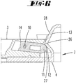
- FIG. 6 shows one of the locking elements 11 and one of the receiving elements 13 in a longitudinal section according to the in FIG. 5 shown line VI.
- the locking element 11 is completely locked behind the undercut 12 of the receiving element 13.
- the locking element 11 slips with its free end portion during the displacement of the oscillating plate 3 relative to the support plate 4 on the latching cam of the receiving element 13 along.
- the latching element 11 is displaced in the region of a vertex 26 of the latching curve maximum in the guide device 14, wherein this displacement takes place counter to the restoring force of the spring element 10.
- the latching element 11 is displaced out of the guide device 14 due to the restoring force of the spring element 10, namely behind that of the receiving element 13 provided undercut 12.
- the spring element 10 retains a bias.
- connection of the carrier plate 4 with the cleaning device 1, namely the oscillating plate 3, now works so that a user deposits the carrier plate 4 on a surface to be cleaned and the cleaning device 1 with the oscillating plate 3 leads over until the centering means 23, 24 of the carrier plate 4 can engage in the centering 25 of the vibrating plate 3.
- the support plate 4 is adjusted relative to the vibrating plate 3, so that subsequently a latching can take place.
- the user pushes the cleaning device 1 with the aid of the weight of the cleaning device 1 on the support plate 4 until the corresponding fastening means 6, 7 of the support plate 4 and the swing plate 3 engage.
- the latching then takes place in detail as explained above with displacement of the latching element 11 against the restoring force of the spring element 10 until the latching element 11 engages in the receiving element 13 of the support plate 4.
- the user tilts the cleaning device 1 into a position tilted relative to the surface to be cleaned, a so-called sack truck position.
- the support plate 4 is lifted with the cleaning element 5 disposed thereon of the surface to be cleaned and the actuating portion 15 is located above a wheel of the cleaning device 1.
- an actuator within the housing of the cleaning device. 1 to pivot, whereby the actuator presses against the support plate 4 and displaced relative to the swing plate 3.
- the bias of the spring element 10 supports a loosening of the corresponding fastener pair 8, 9, so that the oscillating plate 3 can then be removed from the support plate 4 also in the region of the corresponding other fastener pair 8, 9.
Landscapes
- Brushes (AREA)
- Cleaning Implements For Floors, Carpets, Furniture, Walls, And The Like (AREA)
- Cleaning By Liquid Or Steam (AREA)
Applications Claiming Priority (1)
| Application Number | Priority Date | Filing Date | Title |
|---|---|---|---|
| DE102017116673.4A DE102017116673A1 (de) | 2017-07-24 | 2017-07-24 | Reinigungseinrichtung mit einer motorisch angetriebenen Schwingplatte |
Publications (2)
| Publication Number | Publication Date |
|---|---|
| EP3449794A1 true EP3449794A1 (fr) | 2019-03-06 |
| EP3449794B1 EP3449794B1 (fr) | 2020-06-17 |
Family
ID=63014363
Family Applications (1)
| Application Number | Title | Priority Date | Filing Date |
|---|---|---|---|
| EP18184640.3A Active EP3449794B1 (fr) | 2017-07-24 | 2018-07-20 | Dispositif de nettoyage doté d'une plaque oscillante à entraînement par moteur |
Country Status (6)
| Country | Link |
|---|---|
| EP (1) | EP3449794B1 (fr) |
| JP (1) | JP2019048038A (fr) |
| CN (1) | CN109288460B (fr) |
| DE (1) | DE102017116673A1 (fr) |
| ES (1) | ES2818974T3 (fr) |
| TW (1) | TW201907849A (fr) |
Families Citing this family (3)
| Publication number | Priority date | Publication date | Assignee | Title |
|---|---|---|---|---|
| CN113520224A (zh) * | 2020-04-13 | 2021-10-22 | 深圳赤马人工智能有限公司 | 快速拆装清洁刷组件的清洁机器人 |
| JP2021186739A (ja) * | 2020-05-29 | 2021-12-13 | Asti株式会社 | 拭取清掃具と拭取清掃方法 |
| CN222091581U (zh) * | 2024-01-02 | 2024-12-03 | 宁波博瑞德凯国际贸易有限公司 | 一种震动式清洁拖把 |
Citations (4)
| Publication number | Priority date | Publication date | Assignee | Title |
|---|---|---|---|---|
| US1693919A (en) * | 1924-02-12 | 1928-12-04 | Floorola Corp | Brush holder for floor polishers |
| DE102010000378A1 (de) * | 2010-02-11 | 2011-08-11 | Vorwerk & Co. Interholding GmbH, 42275 | Bodenwischgerät sowie Wischtuchträger und Reinigungstuch für ein solches Bodenwischgerät |
| DE102011050181A1 (de) * | 2010-05-25 | 2011-12-01 | Vorwerk & Co. Interholding Gmbh | Bodenwischgerät |
| EP2578131A1 (fr) * | 2011-10-04 | 2013-04-10 | Vorwerk & Co. Interholding GmbH | Appareil de nettoyage des sols ainsi qu'un corps entraîné par oscillation par rapport à une pièce fixe |
Family Cites Families (5)
| Publication number | Priority date | Publication date | Assignee | Title |
|---|---|---|---|---|
| CN2318968Y (zh) * | 1998-03-11 | 1999-05-19 | 吴孝景 | 多用拖把 |
| US9295365B2 (en) * | 2007-02-21 | 2016-03-29 | Bissell Homecare, Inc. | Extractor with auxiliary fluid dispenser |
| KR100831619B1 (ko) * | 2007-04-12 | 2008-05-26 | 주식회사 마미로봇 | 로봇청소기 부직포 걸레 고정구조 |
| KR101253245B1 (ko) * | 2010-09-06 | 2013-04-16 | 한경희 | 스팀청소기 |
| CN203354473U (zh) * | 2013-06-19 | 2013-12-25 | 业展电器(深圳)有限公司 | 自动地板清洁机 |
-
2017
- 2017-07-24 DE DE102017116673.4A patent/DE102017116673A1/de not_active Withdrawn
-
2018
- 2018-07-19 JP JP2018135565A patent/JP2019048038A/ja active Pending
- 2018-07-20 EP EP18184640.3A patent/EP3449794B1/fr active Active
- 2018-07-20 ES ES18184640T patent/ES2818974T3/es active Active
- 2018-07-23 TW TW107125361A patent/TW201907849A/zh unknown
- 2018-07-24 CN CN201810819045.XA patent/CN109288460B/zh active Active
Patent Citations (4)
| Publication number | Priority date | Publication date | Assignee | Title |
|---|---|---|---|---|
| US1693919A (en) * | 1924-02-12 | 1928-12-04 | Floorola Corp | Brush holder for floor polishers |
| DE102010000378A1 (de) * | 2010-02-11 | 2011-08-11 | Vorwerk & Co. Interholding GmbH, 42275 | Bodenwischgerät sowie Wischtuchträger und Reinigungstuch für ein solches Bodenwischgerät |
| DE102011050181A1 (de) * | 2010-05-25 | 2011-12-01 | Vorwerk & Co. Interholding Gmbh | Bodenwischgerät |
| EP2578131A1 (fr) * | 2011-10-04 | 2013-04-10 | Vorwerk & Co. Interholding GmbH | Appareil de nettoyage des sols ainsi qu'un corps entraîné par oscillation par rapport à une pièce fixe |
Also Published As
| Publication number | Publication date |
|---|---|
| DE102017116673A1 (de) | 2019-02-14 |
| EP3449794B1 (fr) | 2020-06-17 |
| CN109288460A (zh) | 2019-02-01 |
| JP2019048038A (ja) | 2019-03-28 |
| CN109288460B (zh) | 2021-06-22 |
| ES2818974T3 (es) | 2021-04-14 |
| TW201907849A (zh) | 2019-03-01 |
Similar Documents
| Publication | Publication Date | Title |
|---|---|---|
| EP2934268B1 (fr) | Brosse de nettoyage pour un appareil de nettoyage de sol et appareil de nettoyage de sol avec une brosse de nettoyage | |
| EP2578131B1 (fr) | Appareil de nettoyage des sols ainsi qu'un corps entraîné par oscillation par rapport à une pièce fixe | |
| EP1899116B1 (fr) | Appareil mobile pour nettoyer le sol | |
| DE202012012850U1 (de) | Exfollationshandgerät | |
| DE3403246A1 (de) | Elektromotorisch verstellbarer fahrzeugsitz | |
| EP3612696A1 (fr) | Système de poignée de porte d'un véhicule automobile | |
| DE4100333A1 (de) | Mechanismus zur hoeheneinstellung von bodenreinigungsgeraeten | |
| DE102010038026A1 (de) | Staubsaugerdüse mit Magnetverriegelung | |
| EP3449794B1 (fr) | Dispositif de nettoyage doté d'une plaque oscillante à entraînement par moteur | |
| DE102004061855A1 (de) | Saugbürste für einen Staubsauger | |
| DE102014113517B4 (de) | Selbstreinigendes Bürstensystem zum Reinigen von Oberflächen | |
| DE202006007395U1 (de) | Vakuumsaughalter mit Lösestellungsarretierung | |
| EP2615959B1 (fr) | Système d'entraînement pour un dispositif de nettoyage et dispositiv de nettoyage | |
| DE102017118379A1 (de) | Reinigungseinrichtung mit einer motorisch angetriebenen Schwingplatte | |
| DE3415637A1 (de) | Fussbodenkehrmaschine mit verbesserter treibradkonstruktion | |
| DE2146316A1 (de) | Staubsaugerwerkzeug mit zwei Ar beitsghedern | |
| WO2006061045A1 (fr) | Appareil de nettoyage de sol | |
| EP3449793B1 (fr) | Dispositif de nettoyage doté d'une plaque oscillante motorisée | |
| EP3185742B1 (fr) | Buse d'aspiration et aspirateur pour surfaces dures | |
| DE1655409B2 (de) | Scheibenwischer-doppelarm | |
| EP2018821B1 (fr) | Dispositif de nettoyage pour une machine de nettoyage du sol et machine de nettoyage du sol dotée d'un tel dispositif de nettoyage | |
| EP0993265A1 (fr) | Appareil nettoyeur | |
| EP3517685B1 (fr) | Pièce rapportée pour une machine de nettoyage du sol | |
| DE102018003607B3 (de) | Scharnier-Vorrichtung | |
| DE60113670T2 (de) | Türgriff für ein Kraftfahrzeug |
Legal Events
| Date | Code | Title | Description |
|---|---|---|---|
| PUAI | Public reference made under article 153(3) epc to a published international application that has entered the european phase |
Free format text: ORIGINAL CODE: 0009012 |
|
| STAA | Information on the status of an ep patent application or granted ep patent |
Free format text: STATUS: THE APPLICATION HAS BEEN PUBLISHED |
|
| AK | Designated contracting states |
Kind code of ref document: A1 Designated state(s): AL AT BE BG CH CY CZ DE DK EE ES FI FR GB GR HR HU IE IS IT LI LT LU LV MC MK MT NL NO PL PT RO RS SE SI SK SM TR |
|
| AX | Request for extension of the european patent |
Extension state: BA ME |
|
| STAA | Information on the status of an ep patent application or granted ep patent |
Free format text: STATUS: REQUEST FOR EXAMINATION WAS MADE |
|
| 17P | Request for examination filed |
Effective date: 20190904 |
|
| RBV | Designated contracting states (corrected) |
Designated state(s): AL AT BE BG CH CY CZ DE DK EE ES FI FR GB GR HR HU IE IS IT LI LT LU LV MC MK MT NL NO PL PT RO RS SE SI SK SM TR |
|
| RIC1 | Information provided on ipc code assigned before grant |
Ipc: A47L 11/12 20060101ALI20191113BHEP Ipc: A47L 11/06 20060101AFI20191113BHEP Ipc: A47L 11/40 20060101ALI20191113BHEP |
|
| GRAP | Despatch of communication of intention to grant a patent |
Free format text: ORIGINAL CODE: EPIDOSNIGR1 |
|
| STAA | Information on the status of an ep patent application or granted ep patent |
Free format text: STATUS: GRANT OF PATENT IS INTENDED |
|
| INTG | Intention to grant announced |
Effective date: 20200107 |
|
| GRAS | Grant fee paid |
Free format text: ORIGINAL CODE: EPIDOSNIGR3 |
|
| GRAA | (expected) grant |
Free format text: ORIGINAL CODE: 0009210 |
|
| STAA | Information on the status of an ep patent application or granted ep patent |
Free format text: STATUS: THE PATENT HAS BEEN GRANTED |
|
| AK | Designated contracting states |
Kind code of ref document: B1 Designated state(s): AL AT BE BG CH CY CZ DE DK EE ES FI FR GB GR HR HU IE IS IT LI LT LU LV MC MK MT NL NO PL PT RO RS SE SI SK SM TR |
|
| REG | Reference to a national code |
Ref country code: GB Ref legal event code: FG4D Free format text: NOT ENGLISH |
|
| REG | Reference to a national code |
Ref country code: CH Ref legal event code: EP |
|
| REG | Reference to a national code |
Ref country code: IE Ref legal event code: FG4D Free format text: LANGUAGE OF EP DOCUMENT: GERMAN |
|
| REG | Reference to a national code |
Ref country code: DE Ref legal event code: R096 Ref document number: 502018001675 Country of ref document: DE |
|
| REG | Reference to a national code |
Ref country code: AT Ref legal event code: REF Ref document number: 1280331 Country of ref document: AT Kind code of ref document: T Effective date: 20200715 |
|
| PG25 | Lapsed in a contracting state [announced via postgrant information from national office to epo] |
Ref country code: FI Free format text: LAPSE BECAUSE OF FAILURE TO SUBMIT A TRANSLATION OF THE DESCRIPTION OR TO PAY THE FEE WITHIN THE PRESCRIBED TIME-LIMIT Effective date: 20200617 Ref country code: NO Free format text: LAPSE BECAUSE OF FAILURE TO SUBMIT A TRANSLATION OF THE DESCRIPTION OR TO PAY THE FEE WITHIN THE PRESCRIBED TIME-LIMIT Effective date: 20200917 Ref country code: GR Free format text: LAPSE BECAUSE OF FAILURE TO SUBMIT A TRANSLATION OF THE DESCRIPTION OR TO PAY THE FEE WITHIN THE PRESCRIBED TIME-LIMIT Effective date: 20200918 Ref country code: SE Free format text: LAPSE BECAUSE OF FAILURE TO SUBMIT A TRANSLATION OF THE DESCRIPTION OR TO PAY THE FEE WITHIN THE PRESCRIBED TIME-LIMIT Effective date: 20200617 Ref country code: LT Free format text: LAPSE BECAUSE OF FAILURE TO SUBMIT A TRANSLATION OF THE DESCRIPTION OR TO PAY THE FEE WITHIN THE PRESCRIBED TIME-LIMIT Effective date: 20200617 |
|
| PGFP | Annual fee paid to national office [announced via postgrant information from national office to epo] |
Ref country code: CZ Payment date: 20200813 Year of fee payment: 3 |
|
| REG | Reference to a national code |
Ref country code: LT Ref legal event code: MG4D |
|
| REG | Reference to a national code |
Ref country code: NL Ref legal event code: MP Effective date: 20200617 |
|
| PG25 | Lapsed in a contracting state [announced via postgrant information from national office to epo] |
Ref country code: HR Free format text: LAPSE BECAUSE OF FAILURE TO SUBMIT A TRANSLATION OF THE DESCRIPTION OR TO PAY THE FEE WITHIN THE PRESCRIBED TIME-LIMIT Effective date: 20200617 Ref country code: BG Free format text: LAPSE BECAUSE OF FAILURE TO SUBMIT A TRANSLATION OF THE DESCRIPTION OR TO PAY THE FEE WITHIN THE PRESCRIBED TIME-LIMIT Effective date: 20200917 Ref country code: RS Free format text: LAPSE BECAUSE OF FAILURE TO SUBMIT A TRANSLATION OF THE DESCRIPTION OR TO PAY THE FEE WITHIN THE PRESCRIBED TIME-LIMIT Effective date: 20200617 Ref country code: LV Free format text: LAPSE BECAUSE OF FAILURE TO SUBMIT A TRANSLATION OF THE DESCRIPTION OR TO PAY THE FEE WITHIN THE PRESCRIBED TIME-LIMIT Effective date: 20200617 |
|
| PG25 | Lapsed in a contracting state [announced via postgrant information from national office to epo] |
Ref country code: NL Free format text: LAPSE BECAUSE OF FAILURE TO SUBMIT A TRANSLATION OF THE DESCRIPTION OR TO PAY THE FEE WITHIN THE PRESCRIBED TIME-LIMIT Effective date: 20200617 Ref country code: AL Free format text: LAPSE BECAUSE OF FAILURE TO SUBMIT A TRANSLATION OF THE DESCRIPTION OR TO PAY THE FEE WITHIN THE PRESCRIBED TIME-LIMIT Effective date: 20200617 |
|
| PG25 | Lapsed in a contracting state [announced via postgrant information from national office to epo] |
Ref country code: EE Free format text: LAPSE BECAUSE OF FAILURE TO SUBMIT A TRANSLATION OF THE DESCRIPTION OR TO PAY THE FEE WITHIN THE PRESCRIBED TIME-LIMIT Effective date: 20200617 Ref country code: SM Free format text: LAPSE BECAUSE OF FAILURE TO SUBMIT A TRANSLATION OF THE DESCRIPTION OR TO PAY THE FEE WITHIN THE PRESCRIBED TIME-LIMIT Effective date: 20200617 Ref country code: RO Free format text: LAPSE BECAUSE OF FAILURE TO SUBMIT A TRANSLATION OF THE DESCRIPTION OR TO PAY THE FEE WITHIN THE PRESCRIBED TIME-LIMIT Effective date: 20200617 Ref country code: PT Free format text: LAPSE BECAUSE OF FAILURE TO SUBMIT A TRANSLATION OF THE DESCRIPTION OR TO PAY THE FEE WITHIN THE PRESCRIBED TIME-LIMIT Effective date: 20201019 |
|
| PG25 | Lapsed in a contracting state [announced via postgrant information from national office to epo] |
Ref country code: PL Free format text: LAPSE BECAUSE OF FAILURE TO SUBMIT A TRANSLATION OF THE DESCRIPTION OR TO PAY THE FEE WITHIN THE PRESCRIBED TIME-LIMIT Effective date: 20200617 Ref country code: SK Free format text: LAPSE BECAUSE OF FAILURE TO SUBMIT A TRANSLATION OF THE DESCRIPTION OR TO PAY THE FEE WITHIN THE PRESCRIBED TIME-LIMIT Effective date: 20200617 Ref country code: IS Free format text: LAPSE BECAUSE OF FAILURE TO SUBMIT A TRANSLATION OF THE DESCRIPTION OR TO PAY THE FEE WITHIN THE PRESCRIBED TIME-LIMIT Effective date: 20201017 |
|
| REG | Reference to a national code |
Ref country code: DE Ref legal event code: R097 Ref document number: 502018001675 Country of ref document: DE |
|
| PG25 | Lapsed in a contracting state [announced via postgrant information from national office to epo] |
Ref country code: MC Free format text: LAPSE BECAUSE OF FAILURE TO SUBMIT A TRANSLATION OF THE DESCRIPTION OR TO PAY THE FEE WITHIN THE PRESCRIBED TIME-LIMIT Effective date: 20200617 |
|
| REG | Reference to a national code |
Ref country code: ES Ref legal event code: FG2A Ref document number: 2818974 Country of ref document: ES Kind code of ref document: T3 Effective date: 20210414 |
|
| PLBE | No opposition filed within time limit |
Free format text: ORIGINAL CODE: 0009261 |
|
| STAA | Information on the status of an ep patent application or granted ep patent |
Free format text: STATUS: NO OPPOSITION FILED WITHIN TIME LIMIT |
|
| REG | Reference to a national code |
Ref country code: BE Ref legal event code: MM Effective date: 20200731 |
|
| PG25 | Lapsed in a contracting state [announced via postgrant information from national office to epo] |
Ref country code: DK Free format text: LAPSE BECAUSE OF FAILURE TO SUBMIT A TRANSLATION OF THE DESCRIPTION OR TO PAY THE FEE WITHIN THE PRESCRIBED TIME-LIMIT Effective date: 20200617 Ref country code: LU Free format text: LAPSE BECAUSE OF NON-PAYMENT OF DUE FEES Effective date: 20200720 |
|
| 26N | No opposition filed |
Effective date: 20210318 |
|
| PG25 | Lapsed in a contracting state [announced via postgrant information from national office to epo] |
Ref country code: SI Free format text: LAPSE BECAUSE OF FAILURE TO SUBMIT A TRANSLATION OF THE DESCRIPTION OR TO PAY THE FEE WITHIN THE PRESCRIBED TIME-LIMIT Effective date: 20200617 Ref country code: BE Free format text: LAPSE BECAUSE OF NON-PAYMENT OF DUE FEES Effective date: 20200731 |
|
| PG25 | Lapsed in a contracting state [announced via postgrant information from national office to epo] |
Ref country code: IE Free format text: LAPSE BECAUSE OF NON-PAYMENT OF DUE FEES Effective date: 20200720 |
|
| REG | Reference to a national code |
Ref country code: CH Ref legal event code: PL |
|
| PG25 | Lapsed in a contracting state [announced via postgrant information from national office to epo] |
Ref country code: LI Free format text: LAPSE BECAUSE OF NON-PAYMENT OF DUE FEES Effective date: 20210731 Ref country code: CH Free format text: LAPSE BECAUSE OF NON-PAYMENT OF DUE FEES Effective date: 20210731 |
|
| PG25 | Lapsed in a contracting state [announced via postgrant information from national office to epo] |
Ref country code: TR Free format text: LAPSE BECAUSE OF FAILURE TO SUBMIT A TRANSLATION OF THE DESCRIPTION OR TO PAY THE FEE WITHIN THE PRESCRIBED TIME-LIMIT Effective date: 20200617 Ref country code: MT Free format text: LAPSE BECAUSE OF FAILURE TO SUBMIT A TRANSLATION OF THE DESCRIPTION OR TO PAY THE FEE WITHIN THE PRESCRIBED TIME-LIMIT Effective date: 20200617 Ref country code: CZ Free format text: LAPSE BECAUSE OF NON-PAYMENT OF DUE FEES Effective date: 20210720 Ref country code: CY Free format text: LAPSE BECAUSE OF FAILURE TO SUBMIT A TRANSLATION OF THE DESCRIPTION OR TO PAY THE FEE WITHIN THE PRESCRIBED TIME-LIMIT Effective date: 20200617 |
|
| PG25 | Lapsed in a contracting state [announced via postgrant information from national office to epo] |
Ref country code: MK Free format text: LAPSE BECAUSE OF FAILURE TO SUBMIT A TRANSLATION OF THE DESCRIPTION OR TO PAY THE FEE WITHIN THE PRESCRIBED TIME-LIMIT Effective date: 20200617 |
|
| GBPC | Gb: european patent ceased through non-payment of renewal fee |
Effective date: 20220720 |
|
| PG25 | Lapsed in a contracting state [announced via postgrant information from national office to epo] |
Ref country code: GB Free format text: LAPSE BECAUSE OF NON-PAYMENT OF DUE FEES Effective date: 20220720 |
|
| P01 | Opt-out of the competence of the unified patent court (upc) registered |
Effective date: 20230517 |
|
| REG | Reference to a national code |
Ref country code: AT Ref legal event code: MM01 Ref document number: 1280331 Country of ref document: AT Kind code of ref document: T Effective date: 20230720 |
|
| PG25 | Lapsed in a contracting state [announced via postgrant information from national office to epo] |
Ref country code: AT Free format text: LAPSE BECAUSE OF NON-PAYMENT OF DUE FEES Effective date: 20230720 |
|
| PG25 | Lapsed in a contracting state [announced via postgrant information from national office to epo] |
Ref country code: AT Free format text: LAPSE BECAUSE OF NON-PAYMENT OF DUE FEES Effective date: 20230720 |
|
| PGFP | Annual fee paid to national office [announced via postgrant information from national office to epo] |
Ref country code: ES Payment date: 20250819 Year of fee payment: 8 |
|
| PGFP | Annual fee paid to national office [announced via postgrant information from national office to epo] |
Ref country code: DE Payment date: 20250722 Year of fee payment: 8 |
|
| PGFP | Annual fee paid to national office [announced via postgrant information from national office to epo] |
Ref country code: IT Payment date: 20250731 Year of fee payment: 8 |
|
| PGFP | Annual fee paid to national office [announced via postgrant information from national office to epo] |
Ref country code: FR Payment date: 20250723 Year of fee payment: 8 |
|
| PGFP | Annual fee paid to national office [announced via postgrant information from national office to epo] |
Ref country code: AT Payment date: 20260410 Year of fee payment: 5 |