EP3449888B1 - Appui-tête pour table d'opération - Google Patents
Appui-tête pour table d'opération Download PDFInfo
- Publication number
- EP3449888B1 EP3449888B1 EP18187953.7A EP18187953A EP3449888B1 EP 3449888 B1 EP3449888 B1 EP 3449888B1 EP 18187953 A EP18187953 A EP 18187953A EP 3449888 B1 EP3449888 B1 EP 3449888B1
- Authority
- EP
- European Patent Office
- Prior art keywords
- head
- patient
- holding
- holding element
- support element
- Prior art date
- Legal status (The legal status is an assumption and is not a legal conclusion. Google has not performed a legal analysis and makes no representation as to the accuracy of the status listed.)
- Active
Links
Images

Classifications
-
- A—HUMAN NECESSITIES
- A61—MEDICAL OR VETERINARY SCIENCE; HYGIENE
- A61G—TRANSPORT, PERSONAL CONVEYANCES, OR ACCOMMODATION SPECIALLY ADAPTED FOR PATIENTS OR DISABLED PERSONS; OPERATING TABLES OR CHAIRS; CHAIRS FOR DENTISTRY; FUNERAL DEVICES
- A61G13/00—Operating tables; Auxiliary appliances therefor
- A61G13/10—Parts, details or accessories
- A61G13/12—Rests specially adapted therefor; Arrangements of patient-supporting surfaces
- A61G13/1205—Rests specially adapted therefor; Arrangements of patient-supporting surfaces for specific parts of the body
- A61G13/121—Head or neck
Definitions
- the invention relates to a headrest for operating tables with an arc-shaped support element for supporting the back of a patient's head and with a first and a second holding element for lateral support on the patient's head, the two holding elements being pivotable relative to the support element, with at least one fastening band for connecting the front end regions of the two holding elements and for contacting the front head region of the patient is provided, the first and second holding elements being articulated individually pivotably about a first and a second axis of rotation on the support element, the pivoting path of each holding element in the pivoted-up position thereof by one limit stop arranged on the outside of the support element is limited.
- a patient is placed supine on an operating table.
- a headrest is attached to the operating table, by means of which the head is securely fixed during the operation to ensure that the operation can take place with the lowest possible risk for the patient.
- a headrest which has a first holding element mounted about a first axis of rotation for enclosing a first side of a patient's head receivable in a receiving area of the headrest and a second holding element mounted about a second axis of rotation for enclosing a second side of the patient's head, wherein the first holding element and the second holding element in a coupling area with the help of at least of a coupling element are coupled to one another such that when one of the holding elements is rotated, the coupling element likewise rotates the other holding element.
- a stationary support element is provided between the coupling area and the receiving area for supporting the head received in the receiving area.
- the coupling element preferably consists of a gearwheel gear, ie both holding elements each have a gearwheel segment, the two gearwheel segments being in engagement with one another.
- This design of the headrest allows a very simple operation for adjusting the holding elements, since only one holding element has to be actuated and the other holding element is pivoted synchronously and evenly by the coupling element.
- both holding elements can only be operated simultaneously and synchronously, so that an exact adaptation to the respective head shape is difficult or not possible, especially when the patient's head is not exactly in the middle of the receiving area.
- the object of the invention is to provide a headrest for operating tables which is simple in construction, easy to use and can be adapted to the respective head positioning situation and the respective head shape.
- the respective stop surface of the respective end stop is spaced further apart from the adjacent outer edge of the support element than the respective axis of rotation, wherein a displaceable sliding piece is arranged on the outside of each holding element, which is designed such that it is between a first End position, in which it does not protrude beyond the edge of the holding element facing the support element, and is displaceable in a second end position in which it rests on the stop surface of the associated end stop.
- the headrest is thus of simple construction, since the two holding elements are each articulated individually on the support element and no coupling gear is provided. Since each holding element can be pivoted individually, an exact adaptation to the head shape or head position is possible, i.e. Both holding elements can be swiveled in individually to lie on the respective side of the patient's head. In the maximally swiveled-out position, both holding elements lie against the end stop of the supporting element, so that they are in an approximately horizontal position and the holding elements in this position serve as a safe supporting surface for an anesthetist during the introduction of anesthesia or during other activities. The patient's head is held securely in this position due to the arched design of the support element. By simply pivoting the holding elements individually and connecting the end regions of the two holding elements with at least one fastening strap, secure helmet-like support of the patient's head in the headrest is then ensured before the operation begins.
- the arrangement of the end stops ensures that when the two holding elements are pivoted open, they rest approximately horizontally on the end stop.
- the operation of the headrest can be significantly simplified by the slide on the respective holding element.
- the respective holding element is first pivoted into a vertical position and the slider is moved beyond the edge of the holding element to the associated end stop until it lies against the stop surface of the end stop.
- the respective holding element is secured against inadvertent folding outwards out of the vertical position by the slide piece lying against the associated end stop, and it can then only be pivoted further inwards against the side of the patient's head.
- the slider is guided on the holding element.
- the sliding piece can have guide pins on the back, which engage in guides on the holding element.
- the sliding piece has an elongated hole in which a locking screw engages.
- the slider can be locked in the respective position, usually in one of the two end positions, by tightening the locking screw.
- first fastening band enclosing the patient's forehead and the second fastening band surrounding the patient's chin. This guarantees an almost helmet-like securing of the head.
- the respective fastening tape is designed to be variable in length and additionally or alternatively consists of an elastic material.
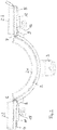
- a headrest for operating tables is generally designated 1.
- This headrest 1 initially has an arcuate support element 2, which serves to support the back of a patient's head.
- This support element 2 has on its rear side a fastening element 3 for fastening a holding arm, not shown, of an operating table.
- the headrest 1 has a first holding element 4 and a second holding element 5.
- Each of these two holding elements 4, 5 is used for lateral contact on one side of a patient's head.
- Both holding elements 4, 5 are hinged relative to the support element 2.
- the first holding element 4 is articulated individually pivotably on the supporting element 2 about a first axis of rotation 6 in a first edge region of the support element 2 and the second holding element 5 about a second axis of rotation 7 in the second edge region of the support element.
- each holding element 4, 5 in the pivoted open position is in each case limited by an end stop 8, 9 arranged on the outside of the support element 2.
- These two end stops 8, 9 can be screwed onto the support element 2, for example.
- Corresponding fastening screws are designated by 10.
- the respective stop surface 8a, 9a of the respective end stop 8, 9 is spaced further apart from the adjacent outer edge 2a or 2b of the support element 2 than the respective axis of rotation 6, 7. The exact distance of the respective stop surface 8a, 9a from the associated outer edge 2a, 2b of the support element 2 determines the maximum pivotability of the holding elements 4, 5 in the pivoted-out position.
- the end stops 8, 9 are preferably arranged such that the holding elements 4 and 5 are in the pivoted-out position approximately in a horizontal position. This position is in Fig. 2 shown. In this maximally swiveled-out position of the two holding elements 4, 5, each holding element 4, 5 can serve as a support surface for an anesthetist or the like before the actual start of an operation.
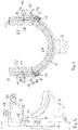
- each holding element 4, 5 there is a displaceable sliding piece 11, 12, which is designed such that it is between a first end position, in which it does not project beyond the edge of the holding element 4, 5 facing the supporting element 2, and a second End position is displaceable, in which it bears against the stop surface 8a, 9a of the associated end stop 8, 9.
- the first end position is in Fig. 4 left for the holding element 4 and the second end position is in Fig. 4 shown on the right for the second holding element 5.
- the slider 11, 12 is guided on the holding element 4, 5, respectively.
- the slider 11, 12 can have guide pins on the back which engage in guides on the holding element, which is not shown in the drawing.
- the respective slider 11, 12 has an elongated hole 13, 14, in which a locking screw 15, 16 engages.
- This locking screw 15, 16 is screwed into a corresponding bore 17, 18 with an internal thread in the holding element 4, 5.
- the headrest 1 also preferably has two fastening straps, namely a first fastening strap 19 for enclosing the patient's forehead and a second fastening strap 20 for enclosing the patient's chin. Both fastening tapes 19, 20 are preferably variable in length and alternatively or additionally designed to be elastic.
- Both the arched support element 2 and the two holding elements 4 and 5 and possibly the fastening straps 19, 20 are each provided on the inside facing the patient's head with suitable pads 21, 22, 23, 24 and 25.
- the patient Before the start of an operation, in particular a shoulder operation, the patient is placed in a supine position on an operating table, not shown, in such a way that his head or back of the head is located on the arch-shaped support element 2.
- the two holding elements 4 and 5 are pivoted open completely, ie in the position according to Fig. 2 , so arranged approximately horizontally.
- the patient In this position of the headrest, the patient can be intubated, for example, by an anesthetist, who can be supported on one of the two holding elements 4 or 5.
- the head is already securely held in the arcuate support element 2.
- the two holding elements 4 and 5 are pivoted vertically upwards and the two sliding pieces 11 and 12 are moved down after loosening the fastening screws 17 and 18 until they abut the stop surface 8a, 9a of the end stop 8 and 9, respectively .
- the two fastening straps 19 and 20 are closed and tightened. The two holding elements 4 and 5 can pivot inward further until they rest against the respective head side of the patient.
- the procedure for loosening the headrest 1 is reversed: first the fastening straps 10 and 20 and the fastening screws 17 and 18 are loosened and then the sliding pieces 11, 12 are pushed up into the first end position and locked there by screwing in the fastening screws 17 and 18. The holding elements 4 and 5 are thereby released and can be pivoted (opened) into the second end position.
- the two end stops 8, 9 can also be an integral part of the arch-shaped support element 2, that is to say they can be molded on.
- the support element can also be divided symmetrically into two halves in the region of the fastening element 3 and held together by the fastening element 3.
Landscapes
- Health & Medical Sciences (AREA)
- Neurosurgery (AREA)
- Otolaryngology (AREA)
- Engineering & Computer Science (AREA)
- Biomedical Technology (AREA)
- Life Sciences & Earth Sciences (AREA)
- Animal Behavior & Ethology (AREA)
- General Health & Medical Sciences (AREA)
- Public Health (AREA)
- Veterinary Medicine (AREA)
- Accommodation For Nursing Or Treatment Tables (AREA)
Claims (6)
- Appuie-tête pour table d'opération avec un élément d'appui de forme arquée (2) pour poser un arrière de la tête d'un patient et avec un premier et un second élément de retenue (4, 5) pour l'application latérale au niveau de la tête du patient, dans lequel les deux éléments de retenue (4, 5) peuvent pivoter par rapport à l'élément d'appui (2), dans lequel au moins une bande de fixation (19, 20) destinée à relier les zones terminales avant des deux éléments de retenue (4, 5) et à être appliquée au niveau de la zone avant de la tête du patient est prévue, le premier et le second élément de retenue (4, 5) étant articulés respectivement autour d'un premier ou second axe de rotation (6, 7) de façon à pouvoir pivoter individuellement au niveau de l'élément d'appui (2), dans lequel la course de pivotement de chaque élément de retenue (4, 5) est limitée à l'état basculé de celui-ci par respectivement une butée terminale (8, 9) disposée au niveau du côté extérieur de l'élément d'appui (2),
caractérisé en ce que
la surface de butée respective (8a, 9a) de la butée terminale respective (8, 9) est plus éloignée du bord extérieur adjacent (2a, 2b) de l'élément d'appui (2) que l'axe de rotation respectif (6, 7), dans lequel au niveau du côté extérieur de chaque élément de retenue (4, 5) est disposée respectivement une pièce de glissement pouvant coulisser (11, 12), qui est conçue de telle sorte qu'elle peut coulisser entre une première position terminale dans laquelle elle ne dépasse pas du bord de l'élément de retenue (4, 5) tourné vers l'élément d'appui (2) et une deuxième position terminale dans laquelle elle est adjacente à la surface de butée (8a, 9a) de la butée terminale affectée (8, 9). - Appuie-tête selon la revendication 1
caractérisé en ce que
la pièce de glissement (11, 12) est guidée au niveau de l'élément de retenue (4, 5). - Appuie-tête selon la revendication 2,
caractérisé en ce que
la pièce de glissement (11, 12) présente un trou longitudinal (13, 14) dans lequel une vis de réglage (15, 16) est en prise. - Appuie-tête selon l'une quelconque des revendications 1 à 3,
caractérisé en ce que
deux bandes de fixation (19, 20) sont prévues, dans lequel la première bande de fixation (19) entoure le front du patient et la seconde bande de fixation (20) entoure le menton du patient. - Appuie-tête selon l'une quelconque des revendications 1 à 4,
caractérisé en ce que
la bande de fixation respective (19, 20) est conçue de façon à pouvoir être réglable en longueur. - Appuie-tête selon l'une quelconque des revendications 1 à 5,
caractérisé en ce que
la bande de fixation respective (19, 20) est constituée d'un matériau élastique.
Applications Claiming Priority (1)
| Application Number | Priority Date | Filing Date | Title |
|---|---|---|---|
| DE202017105275.3U DE202017105275U1 (de) | 2017-09-01 | 2017-09-01 | Kopfstütze für Operationstische |
Publications (2)
| Publication Number | Publication Date |
|---|---|
| EP3449888A1 EP3449888A1 (fr) | 2019-03-06 |
| EP3449888B1 true EP3449888B1 (fr) | 2020-03-18 |
Family
ID=64745282
Family Applications (1)
| Application Number | Title | Priority Date | Filing Date |
|---|---|---|---|
| EP18187953.7A Active EP3449888B1 (fr) | 2017-09-01 | 2018-08-08 | Appui-tête pour table d'opération |
Country Status (2)
| Country | Link |
|---|---|
| EP (1) | EP3449888B1 (fr) |
| DE (1) | DE202017105275U1 (fr) |
Cited By (1)
| Publication number | Priority date | Publication date | Assignee | Title |
|---|---|---|---|---|
| US11850191B2 (en) | 2020-04-22 | 2023-12-26 | Warsaw Orthopedic, Inc. | Head support and method for use of the head support for positioning a patient relative to a surgical frame |
Families Citing this family (2)
| Publication number | Priority date | Publication date | Assignee | Title |
|---|---|---|---|---|
| CN113648078B (zh) * | 2021-09-27 | 2022-09-27 | 苏州市立医院 | 一种脑血管介入的穿刺定位辅助装置 |
| CN115399740B (zh) * | 2022-08-11 | 2026-02-10 | 中国人民解放军总医院海南医院 | 一种心肺功能衰竭重症监护装置 |
Family Cites Families (4)
| Publication number | Priority date | Publication date | Assignee | Title |
|---|---|---|---|---|
| US4034748A (en) * | 1975-10-28 | 1977-07-12 | Winner Stephen E | Spinal restraint device |
| US8555439B2 (en) * | 2010-11-18 | 2013-10-15 | Allen Medical Systems, Inc. | Padded head support |
| EP2724701B1 (fr) | 2012-10-29 | 2015-04-29 | Maquet GmbH | Support de tête destiné à des tables d'opération |
| CN207627563U (zh) * | 2017-04-19 | 2018-07-20 | 曲敬茹 | 一种眼科手术用头部固定装置 |
-
2017
- 2017-09-01 DE DE202017105275.3U patent/DE202017105275U1/de active Active
-
2018
- 2018-08-08 EP EP18187953.7A patent/EP3449888B1/fr active Active
Non-Patent Citations (1)
| Title |
|---|
| None * |
Cited By (1)
| Publication number | Priority date | Publication date | Assignee | Title |
|---|---|---|---|---|
| US11850191B2 (en) | 2020-04-22 | 2023-12-26 | Warsaw Orthopedic, Inc. | Head support and method for use of the head support for positioning a patient relative to a surgical frame |
Also Published As
| Publication number | Publication date |
|---|---|
| EP3449888A1 (fr) | 2019-03-06 |
| DE202017105275U1 (de) | 2018-12-06 |
Similar Documents
| Publication | Publication Date | Title |
|---|---|---|
| EP3003198B1 (fr) | Dispositif adaptateur pour table d'opération | |
| EP3449888B1 (fr) | Appui-tête pour table d'opération | |
| DE112014001466T5 (de) | Flexibler Arm und Verfahren zu dessen Verwendung | |
| EP2292112B1 (fr) | Casque doté d'une protection pour les yeux | |
| DE2043679A1 (de) | Strammerverschluß an Skischuhen | |
| AT13053U1 (de) | Vorrichtung mit einem verstellbaren Stirnband für einen Schutzhelm | |
| DE102014019679B4 (de) | Faltrollstuhl | |
| DE102014101009A1 (de) | Knochenspreizer mit verdrehbaren Valven | |
| EP2184040A1 (fr) | Pince pour épicondylite | |
| EP1464367B1 (fr) | Sixation de snowboard | |
| EP0372406A2 (fr) | Jugulaire réglable pour casque de protection à l'usage des motocyclistes | |
| EP3421016B1 (fr) | Orthèse de main dynamique | |
| EP0572474B1 (fr) | Dispositif de ligature pour parties du corps | |
| DE4108918C1 (en) | Surgical re-positioning of vertebrae - involves instrument with crossbar and tie-bar fitted with nut and gripper | |
| WO2019048667A1 (fr) | Dispositif de maintien flexible | |
| EP3897476B1 (fr) | Orthèse de genou | |
| EP3988049B1 (fr) | Dispositif distracteur | |
| DE102014101218A1 (de) | Beschlaganordnung | |
| DE102004004576A1 (de) | Lösbare Klemme für einen Helmriemen | |
| DE1280471B (de) | Verstellbare Abduktionsschiene | |
| DE10205217B4 (de) | Reißverschluss mit Schieber | |
| DE102015105450A1 (de) | Vorrichtung mit paralleler Greiffläche | |
| DE2951039C2 (de) | Feststellvorrichtung für das Kopfteil eines Liegenrahmens | |
| LU601243B1 (de) | Eine verstellbare Schienenstützvorrichtung für distale Radiusfrakturen | |
| DE102008013923B4 (de) | Uhrarmband |
Legal Events
| Date | Code | Title | Description |
|---|---|---|---|
| PUAI | Public reference made under article 153(3) epc to a published international application that has entered the european phase |
Free format text: ORIGINAL CODE: 0009012 |
|
| STAA | Information on the status of an ep patent application or granted ep patent |
Free format text: STATUS: THE APPLICATION HAS BEEN PUBLISHED |
|
| AK | Designated contracting states |
Kind code of ref document: A1 Designated state(s): AL AT BE BG CH CY CZ DE DK EE ES FI FR GB GR HR HU IE IS IT LI LT LU LV MC MK MT NL NO PL PT RO RS SE SI SK SM TR |
|
| AX | Request for extension of the european patent |
Extension state: BA ME |
|
| STAA | Information on the status of an ep patent application or granted ep patent |
Free format text: STATUS: REQUEST FOR EXAMINATION WAS MADE |
|
| 17P | Request for examination filed |
Effective date: 20190730 |
|
| RBV | Designated contracting states (corrected) |
Designated state(s): AL AT BE BG CH CY CZ DE DK EE ES FI FR GB GR HR HU IE IS IT LI LT LU LV MC MK MT NL NO PL PT RO RS SE SI SK SM TR |
|
| GRAP | Despatch of communication of intention to grant a patent |
Free format text: ORIGINAL CODE: EPIDOSNIGR1 |
|
| STAA | Information on the status of an ep patent application or granted ep patent |
Free format text: STATUS: GRANT OF PATENT IS INTENDED |
|
| INTG | Intention to grant announced |
Effective date: 20191021 |
|
| GRAS | Grant fee paid |
Free format text: ORIGINAL CODE: EPIDOSNIGR3 |
|
| GRAA | (expected) grant |
Free format text: ORIGINAL CODE: 0009210 |
|
| STAA | Information on the status of an ep patent application or granted ep patent |
Free format text: STATUS: THE PATENT HAS BEEN GRANTED |
|
| AK | Designated contracting states |
Kind code of ref document: B1 Designated state(s): AL AT BE BG CH CY CZ DE DK EE ES FI FR GB GR HR HU IE IS IT LI LT LU LV MC MK MT NL NO PL PT RO RS SE SI SK SM TR |
|
| REG | Reference to a national code |
Ref country code: GB Ref legal event code: FG4D Free format text: NOT ENGLISH |
|
| REG | Reference to a national code |
Ref country code: DE Ref legal event code: R096 Ref document number: 502018000977 Country of ref document: DE |
|
| REG | Reference to a national code |
Ref country code: AT Ref legal event code: REF Ref document number: 1245071 Country of ref document: AT Kind code of ref document: T Effective date: 20200415 Ref country code: IE Ref legal event code: FG4D Free format text: LANGUAGE OF EP DOCUMENT: GERMAN |
|
| PG25 | Lapsed in a contracting state [announced via postgrant information from national office to epo] |
Ref country code: RS Free format text: LAPSE BECAUSE OF FAILURE TO SUBMIT A TRANSLATION OF THE DESCRIPTION OR TO PAY THE FEE WITHIN THE PRESCRIBED TIME-LIMIT Effective date: 20200318 Ref country code: FI Free format text: LAPSE BECAUSE OF FAILURE TO SUBMIT A TRANSLATION OF THE DESCRIPTION OR TO PAY THE FEE WITHIN THE PRESCRIBED TIME-LIMIT Effective date: 20200318 Ref country code: NO Free format text: LAPSE BECAUSE OF FAILURE TO SUBMIT A TRANSLATION OF THE DESCRIPTION OR TO PAY THE FEE WITHIN THE PRESCRIBED TIME-LIMIT Effective date: 20200618 |
|
| REG | Reference to a national code |
Ref country code: NL Ref legal event code: MP Effective date: 20200318 |
|
| PG25 | Lapsed in a contracting state [announced via postgrant information from national office to epo] |
Ref country code: BG Free format text: LAPSE BECAUSE OF FAILURE TO SUBMIT A TRANSLATION OF THE DESCRIPTION OR TO PAY THE FEE WITHIN THE PRESCRIBED TIME-LIMIT Effective date: 20200618 Ref country code: HR Free format text: LAPSE BECAUSE OF FAILURE TO SUBMIT A TRANSLATION OF THE DESCRIPTION OR TO PAY THE FEE WITHIN THE PRESCRIBED TIME-LIMIT Effective date: 20200318 Ref country code: GR Free format text: LAPSE BECAUSE OF FAILURE TO SUBMIT A TRANSLATION OF THE DESCRIPTION OR TO PAY THE FEE WITHIN THE PRESCRIBED TIME-LIMIT Effective date: 20200619 Ref country code: LV Free format text: LAPSE BECAUSE OF FAILURE TO SUBMIT A TRANSLATION OF THE DESCRIPTION OR TO PAY THE FEE WITHIN THE PRESCRIBED TIME-LIMIT Effective date: 20200318 Ref country code: SE Free format text: LAPSE BECAUSE OF FAILURE TO SUBMIT A TRANSLATION OF THE DESCRIPTION OR TO PAY THE FEE WITHIN THE PRESCRIBED TIME-LIMIT Effective date: 20200318 |
|
| REG | Reference to a national code |
Ref country code: LT Ref legal event code: MG4D |
|
| PG25 | Lapsed in a contracting state [announced via postgrant information from national office to epo] |
Ref country code: NL Free format text: LAPSE BECAUSE OF FAILURE TO SUBMIT A TRANSLATION OF THE DESCRIPTION OR TO PAY THE FEE WITHIN THE PRESCRIBED TIME-LIMIT Effective date: 20200318 |
|
| PG25 | Lapsed in a contracting state [announced via postgrant information from national office to epo] |
Ref country code: RO Free format text: LAPSE BECAUSE OF FAILURE TO SUBMIT A TRANSLATION OF THE DESCRIPTION OR TO PAY THE FEE WITHIN THE PRESCRIBED TIME-LIMIT Effective date: 20200318 Ref country code: SK Free format text: LAPSE BECAUSE OF FAILURE TO SUBMIT A TRANSLATION OF THE DESCRIPTION OR TO PAY THE FEE WITHIN THE PRESCRIBED TIME-LIMIT Effective date: 20200318 Ref country code: IS Free format text: LAPSE BECAUSE OF FAILURE TO SUBMIT A TRANSLATION OF THE DESCRIPTION OR TO PAY THE FEE WITHIN THE PRESCRIBED TIME-LIMIT Effective date: 20200718 Ref country code: PT Free format text: LAPSE BECAUSE OF FAILURE TO SUBMIT A TRANSLATION OF THE DESCRIPTION OR TO PAY THE FEE WITHIN THE PRESCRIBED TIME-LIMIT Effective date: 20200812 Ref country code: EE Free format text: LAPSE BECAUSE OF FAILURE TO SUBMIT A TRANSLATION OF THE DESCRIPTION OR TO PAY THE FEE WITHIN THE PRESCRIBED TIME-LIMIT Effective date: 20200318 Ref country code: SM Free format text: LAPSE BECAUSE OF FAILURE TO SUBMIT A TRANSLATION OF THE DESCRIPTION OR TO PAY THE FEE WITHIN THE PRESCRIBED TIME-LIMIT Effective date: 20200318 Ref country code: CZ Free format text: LAPSE BECAUSE OF FAILURE TO SUBMIT A TRANSLATION OF THE DESCRIPTION OR TO PAY THE FEE WITHIN THE PRESCRIBED TIME-LIMIT Effective date: 20200318 Ref country code: LT Free format text: LAPSE BECAUSE OF FAILURE TO SUBMIT A TRANSLATION OF THE DESCRIPTION OR TO PAY THE FEE WITHIN THE PRESCRIBED TIME-LIMIT Effective date: 20200318 |
|
| REG | Reference to a national code |
Ref country code: DE Ref legal event code: R097 Ref document number: 502018000977 Country of ref document: DE |
|
| PLBE | No opposition filed within time limit |
Free format text: ORIGINAL CODE: 0009261 |
|
| STAA | Information on the status of an ep patent application or granted ep patent |
Free format text: STATUS: NO OPPOSITION FILED WITHIN TIME LIMIT |
|
| PG25 | Lapsed in a contracting state [announced via postgrant information from national office to epo] |
Ref country code: ES Free format text: LAPSE BECAUSE OF FAILURE TO SUBMIT A TRANSLATION OF THE DESCRIPTION OR TO PAY THE FEE WITHIN THE PRESCRIBED TIME-LIMIT Effective date: 20200318 Ref country code: DK Free format text: LAPSE BECAUSE OF FAILURE TO SUBMIT A TRANSLATION OF THE DESCRIPTION OR TO PAY THE FEE WITHIN THE PRESCRIBED TIME-LIMIT Effective date: 20200318 Ref country code: IT Free format text: LAPSE BECAUSE OF FAILURE TO SUBMIT A TRANSLATION OF THE DESCRIPTION OR TO PAY THE FEE WITHIN THE PRESCRIBED TIME-LIMIT Effective date: 20200318 |
|
| 26N | No opposition filed |
Effective date: 20201221 |
|
| PG25 | Lapsed in a contracting state [announced via postgrant information from national office to epo] |
Ref country code: PL Free format text: LAPSE BECAUSE OF FAILURE TO SUBMIT A TRANSLATION OF THE DESCRIPTION OR TO PAY THE FEE WITHIN THE PRESCRIBED TIME-LIMIT Effective date: 20200318 |
|
| PG25 | Lapsed in a contracting state [announced via postgrant information from national office to epo] |
Ref country code: MC Free format text: LAPSE BECAUSE OF FAILURE TO SUBMIT A TRANSLATION OF THE DESCRIPTION OR TO PAY THE FEE WITHIN THE PRESCRIBED TIME-LIMIT Effective date: 20200318 |
|
| PG25 | Lapsed in a contracting state [announced via postgrant information from national office to epo] |
Ref country code: LU Free format text: LAPSE BECAUSE OF NON-PAYMENT OF DUE FEES Effective date: 20200808 |
|
| REG | Reference to a national code |
Ref country code: BE Ref legal event code: MM Effective date: 20200831 |
|
| PG25 | Lapsed in a contracting state [announced via postgrant information from national office to epo] |
Ref country code: SI Free format text: LAPSE BECAUSE OF FAILURE TO SUBMIT A TRANSLATION OF THE DESCRIPTION OR TO PAY THE FEE WITHIN THE PRESCRIBED TIME-LIMIT Effective date: 20200318 |
|
| PG25 | Lapsed in a contracting state [announced via postgrant information from national office to epo] |
Ref country code: BE Free format text: LAPSE BECAUSE OF NON-PAYMENT OF DUE FEES Effective date: 20200831 Ref country code: IE Free format text: LAPSE BECAUSE OF NON-PAYMENT OF DUE FEES Effective date: 20200808 |
|
| REG | Reference to a national code |
Ref country code: CH Ref legal event code: PL |
|
| PG25 | Lapsed in a contracting state [announced via postgrant information from national office to epo] |
Ref country code: LI Free format text: LAPSE BECAUSE OF NON-PAYMENT OF DUE FEES Effective date: 20210831 Ref country code: CH Free format text: LAPSE BECAUSE OF NON-PAYMENT OF DUE FEES Effective date: 20210831 |
|
| PG25 | Lapsed in a contracting state [announced via postgrant information from national office to epo] |
Ref country code: TR Free format text: LAPSE BECAUSE OF FAILURE TO SUBMIT A TRANSLATION OF THE DESCRIPTION OR TO PAY THE FEE WITHIN THE PRESCRIBED TIME-LIMIT Effective date: 20200318 Ref country code: MT Free format text: LAPSE BECAUSE OF FAILURE TO SUBMIT A TRANSLATION OF THE DESCRIPTION OR TO PAY THE FEE WITHIN THE PRESCRIBED TIME-LIMIT Effective date: 20200318 Ref country code: CY Free format text: LAPSE BECAUSE OF FAILURE TO SUBMIT A TRANSLATION OF THE DESCRIPTION OR TO PAY THE FEE WITHIN THE PRESCRIBED TIME-LIMIT Effective date: 20200318 |
|
| PG25 | Lapsed in a contracting state [announced via postgrant information from national office to epo] |
Ref country code: MK Free format text: LAPSE BECAUSE OF FAILURE TO SUBMIT A TRANSLATION OF THE DESCRIPTION OR TO PAY THE FEE WITHIN THE PRESCRIBED TIME-LIMIT Effective date: 20200318 Ref country code: AL Free format text: LAPSE BECAUSE OF FAILURE TO SUBMIT A TRANSLATION OF THE DESCRIPTION OR TO PAY THE FEE WITHIN THE PRESCRIBED TIME-LIMIT Effective date: 20200318 |
|
| GBPC | Gb: european patent ceased through non-payment of renewal fee |
Effective date: 20220808 |
|
| P01 | Opt-out of the competence of the unified patent court (upc) registered |
Effective date: 20230525 |
|
| PG25 | Lapsed in a contracting state [announced via postgrant information from national office to epo] |
Ref country code: GB Free format text: LAPSE BECAUSE OF NON-PAYMENT OF DUE FEES Effective date: 20220808 |
|
| REG | Reference to a national code |
Ref country code: DE Ref legal event code: R081 Ref document number: 502018000977 Country of ref document: DE Owner name: SCHMITZ MEDICAL GMBH, DE Free format text: FORMER OWNER: SCHMITZ U. SOEHNE GMBH & CO. KOMMANDITGESELLSCHAFT, 58739 WICKEDE, DE |
|
| REG | Reference to a national code |
Ref country code: AT Ref legal event code: MM01 Ref document number: 1245071 Country of ref document: AT Kind code of ref document: T Effective date: 20230808 |
|
| PG25 | Lapsed in a contracting state [announced via postgrant information from national office to epo] |
Ref country code: AT Free format text: LAPSE BECAUSE OF NON-PAYMENT OF DUE FEES Effective date: 20230808 |
|
| PG25 | Lapsed in a contracting state [announced via postgrant information from national office to epo] |
Ref country code: AT Free format text: LAPSE BECAUSE OF NON-PAYMENT OF DUE FEES Effective date: 20230808 |
|
| PGFP | Annual fee paid to national office [announced via postgrant information from national office to epo] |
Ref country code: DE Payment date: 20250528 Year of fee payment: 8 |
|
| PGFP | Annual fee paid to national office [announced via postgrant information from national office to epo] |
Ref country code: FR Payment date: 20250821 Year of fee payment: 8 |
|
| REG | Reference to a national code |
Ref country code: DE Ref legal event code: R082 Ref document number: 502018000977 Country of ref document: DE Representative=s name: SCHNEIDERS & BEHRENDT PARTMBB, RECHTS- UND PAT, DE |
|
| PGFP | Annual fee paid to national office [announced via postgrant information from national office to epo] |
Ref country code: AT Payment date: 20260410 Year of fee payment: 5 |